1
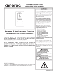
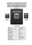
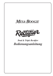
Installation and operating manual Luxury version with stainless steel tank DG-3 Control panel surface-mounted (option) Control panel flush-mounted (option) Specifications: Nominal voltage 3/N/PE/ 400V/50Hz Power output Temperature control range max. 9kW Water feed +30°C to +50°C IP 40 2 to 5 bar External operation panel 5V Computer interface Temperature sensor Lighting Semiconductor Protection class Exhaust fan Feed air fan Drain Housing dimensions Steam outlet Water connction Filling connection for decalcifier USB and RS485 230V or 11,5V 230V 230V ø 20mm (outside) ca. 580 x 435 x 240 ø 35mm (outside) R ¾ " thread ½ " SW 23 SILVER-STEAM luxury version (metal tank) user manual Page: 2 Type overview SILVER-STEAM ! Type Power output L-3.0 3.0 KW L-3.0+Light 3.0 KW L-3.0+Pump 3.0 KW L-3.0+Light/Pump 3.0 KW L-4.5 4.5 KW L-4.5+Light 4.5 KW L-4.5+Pump 4.5 KW L-4.5+Light/Pump 4.5 KW L-6.0 6.0 KW L-6.0+Light 6.0 KW L-6.0+Pump 6.0 KW L-6.0+Light/Pump 6.0 KW L-9.0 9.0 KW L-9.0+Light 9.0 KW L-9.0+Pump 9.0 KW L-9.0+Light/Pump 9.0 KW Lighting transformer Metering pump Item No.: 3198000030 " " 3198100030 " " 3198000130 3198100130 3198000045 " " 3198100045 " " 3198000145 3198100145 3198000060 " " 3198100060 " " 3198000160 3198100160 3198000090 " " 3198100090 " " 3198000190 3198100190 Contents Specifications: ........................................................................................................................... 1 Type overview SILVER-STEAM .............................................................................................. 2 Function .................................................................................................................................... 4 Commissioning.......................................................................................................................... 4 Displays and controls:............................................................................................................... 4 Display ....................................................................................................................................... 5 Operating the steam generator ................................................................................................. 6 Setting the time ..............................................................................................................................................6 Switching steam production on/off...............................................................................................................6 Temperature regulation ............................................................................................................ 6 Timer.......................................................................................................................................... 6 Odou rintensity .......................................................................................................................... 7 Info key ...................................................................................................................................... 7 SILVER-STEAM luxury version (metal tank) user manual Page: 3 Info key blinks ........................................................................................................................... 7 Decalcification timer ..................................................................................................................................... 7 Switching between languages ....................................................................................................................... 8 External operating panel (optional).......................................................................................... 8 External Control Panel Flush-Mounting (Option) ..................................................................................... 9 Rinse program.......................................................................................................................... 10 Program sequence ....................................................................................................................................... 10 Continuous steam generator operation .................................................................................. 10 Exhaust fan.............................................................................................................................. 10 Feed air fan.............................................................................................................................. 10 Coin-operated timer ................................................................................................................. 11 Remote switch .......................................................................................................................... 11 Adjusting water hardness ........................................................................................................ 12 Drainage connections.............................................................................................................. 13 Installation:.............................................................................................................................. 13 Electrical power supply / safety information:......................................................................... 13 Connection to water supply ..................................................................................................... 14 Service information: #................................................................................................................................ 14 Ventilation: .............................................................................................................................. 14 The steam pipeline ................................................................................................................... 15 Steam pipeline connections ......................................................................................................................... 15 Installation of the steam pipeline................................................................................................................ 15 The steam nozzles (set) .................................................................................................... 16 Temperature sensor installation ............................................................................................. 17 Installation: .................................................................................................................................................. 17 Course of action:.......................................................................................................................................... 17 Cubicle lighting........................................................................................................................ 19 Electrical connection ................................................................................................................................... 19 Fusing ........................................................................................................................................................... 19 External transformer .................................................................................................................................. 19 Winter operation ...................................................................................................................... 19 Decalcification ......................................................................................................................... 20 Course of action:.......................................................................................................................................... 20 Completion of decalcification:.................................................................................................................... 20 Odour metering........................................................................................................................ 21 Odour intensity ............................................................................................................................................ 21 Bleeding the fragrance hose........................................................................................................................ 21 Connecting the fragrance unit.................................................................................................................... 22 Fragrance metering pump maintenance.................................................................................................... 22 Course of action ........................................................................................................................................... 22 Troubleshooting checklist for malfunctions........................................................................... 23 Troubleshooting / pilot light ....................................................................................................................... 24 Service terminal ....................................................................................................................... 25 Circuit diagram........................................................................................................................ 30 Wear parts ................................................................................................................................ 30 SILVER-STEAM luxury version (metal tank) user manual Page: 4 Function This high-quality fully automatic steam generator produces steam for steam bath cubicles. All necessary control and operation functions can be carried out using both the steam generator operating pile and the external operating panel (optional). The comfortable microprocessor control system takes over all necessary regulation, control and checking functions. • Filling steam vessel with water. • Automatic refilling of used water. • Freshening of water for improvement of water quality. • Monitoring and regulation of temperature in steam bath cubicle. • Drainage of steam vessel. • Cleaning of steam vessel and level sensor. • Automatic control of exhaust air ventilator. • Automatic control of feed air ventilator. • Automatic fragrance metering (optional). Provision of low voltage safety circuit (12V) for lighting (optional). Commissioning The steam generator must be adjusted to suit the hardness of the water supply before initial startup. You can find more information in the section entitled "Setting the water hardness". Displays and controls: "Steam" key The steam generator is keyed on and off with this key. "Light" key The cubicle lighting is keyed on and off with this key. "Ventilator" key The exhaust fan is keyed on and off outside the operating time using this key. "Fragrance" key The fragrance metering is keyed on and off with this key. SILVER-STEAM luxury version (metal tank) user manual Page: 5 "Aux“ key This key can be used to key additional devices such as vestibule lighting, vestibule ventilation, music systems etc on and off. "i" key (Info key) This key can be used to call up or program information such as device type, operating hours, program version, decalcification timer, language etc. "Temperature" key After this key is pressed, the the wording Temperature and Set temperature is displayed. These can be changed using the Plus or Minus keys. "Clock" key The wording Timer appears in the display after this key is pressed. The time can be changed using the Plus or Minus keys. "Timer" key The wording Timer ON appears in the display after this key is pressed. The timer on time can be changed using the Plus or Minus keys. If you press the key again, the display shows the wording Timer OFF, which can also be changed as above. "Odour intensity" key The wording Odour impulse appears in the display after this key is pressed. The impulse time can be changed using the Plus or Minus keys. If you press the key again, the display shows the wording odour pause, which can also be changed as above. "Plus" key Use this key to increase the value during programming (e.g. time). "Minus" key Use this key to reduce the value during programming (e.g. time). Display Temperature 43,8°C 17:26 steam bath mode Time Operating mode SILVER-STEAM luxury version (metal tank) user manual Page: 6 Operating the steam generator When the steam generator is switched off, the display shows the time. 17:26 Setting the time If you press the "Time" Key, the wording "Time" is shown in the display. 36,4°C 17:26 The time displayed can now be changed using the Plus or Minus keys. time The time shown in the display is saved automatically. Once the time has been programmed, you can press the "Time" key again to return the display to the "initial position" If not, the intelligent microprocessor control system switches the display back to the initial position 10 seconds after the last time the "Plus", "Minus" or "Time" keys were pressed. Switching steam production on/off Steam production is switched on using the "Steam" key. Once started, the 46,4°C 17:26 display shows the time, cubicle temperature and the wording "Steam bath steam bath mode mode". After switching on, any residual water which might have accumulated in small quantities is pumped out, the fresh water feed is opened and the steam vessel is filled with water Once the required water level has been reached, the water feed is automatically stopped and the water starts heating. A few minutes will pass before the actual steam production commences depending on the capacity of the steam generator. Any water used during operation is automatically refilled. The intelligent microprocessor control system monitor steam production continuously and ensures problem-free operation. Small quantities of water are occasionally replaced with fresh water depending on the thermal output, steam production, water consumption and other factors. If required, the microprocessor control system will automatically switch the exhaust fan (if fitted) on and off to improve room climate. When operation has finished, the steam generator is switched off using the "Steam" key mentioned above, and the rinse program is then automatically activated. Once the rinse program has completed, the steam generator switches off automatically. The water container is then empty. Temperature regulation If you press the "Temperature" key, the display shows the set temperature 17:26 (required temperature), and the wording "Temperature" is shown in the 38,1°C set temperature display. The displayed temperature (required temperature) can be individually changed using the "Plus" or "Minus" keys. Settings can be made between 30°C and 50°C.The temperature shown in the display is automatically saved. Once the temperature has been programmed, press the "Temperature" key again to switch the display back to the "initial position". If not, the intelligent microprocessor control system switches the display back to the initial position 10 seconds after the last time the "Plus", "Minus" or "Temperature" keys were pressed. Timer You can use this function to switch the steam generator on or off automatically. If you press the "Timer" key, the wording "Timer ON" is shown in the display. The timer on time displayed can now be changed using the Plus or Minus keys. The time shown in the display is saved automatically. 10:00 on-switch time SILVER-STEAM luxury version (metal tank) user manual Page: 7 Now press the "Timer" key again, and the display will show the wording 20:30 "Timer OFF". Press the "Plus" or "Minus" keys to change the timer off time off-switch time displayed. The time shown in the display is saved automatically. Once the timer has been programmed, press the "Timer " key again to switch the display back to the "initial position". If not, the intelligent microprocessor control system switches the display back to the initial position 10 seconds after the last time the "Plus", "Minus" or "Timer" keys were pressed. If you do not want to switch the steam generator on or off automatically, enter the same times for the switch-on and switch-off values e.g: Time ON 16:00, Time OFF also 16:00. Odou rintensity Use this function to program the odour intensity. If you press the "Odour Seconds intensity" Key, the wording "Odour impulse" is shown in the display. The impulse length displayed can now be changed using the Plus or Minus 01,0 keys. Increasing the impulse length results in longer operation of the odour impulse odour metering pump and therefore an increase in odour intensity. The value shown in the display is automatically saved. Now press the "Odour intensity" key again, and the display will show the wording "Odour pause". Press the "Plus" or "Minus" keys to change the pause length displayed. Increasing the pause length results in a longer Seconds pause between odour injections and therefore reduction of odour intensity. Minutes The time shown in the display is saved automatically. When you are 05:20 finished programming the odour intensity, press the "Odour intensity" key odour pause again to return the display to the "initial position". If not, the intelligent microprocessor control system switches the display back to the 10 seconds after the last time the "Plus", "Minus" or "Odour intensity" keys were pressed. Info key If you press the key, the following messages are shown in the display: Programm version i osf DG3 v.1.00 SN: 1234 9,0 kW Power output Serial number Info key blinks If the pilot light in the Info key is blinking, the decalcification timer has responded (see decalcification timer). The steam generator must now be manually decalcified. Decalcification timer If the key is pressed twice, the following messages are shown in the display: An acoustic signal is sounded when the steam generator is switched on once a decalcification cycle has been completed. In addition, the display shows the wording "Please decalcify". The steam generator must now be decalcified. You can find more information in this section entitled "Decalcification". The timer needs to be reset as follows once decalcification has been completed: 1. Press key twice 2. Press key key 3. Press The decalcification timer has now been deleted. You can now use the steam generator as usual. If the "Please decalcify" message is shown in the display again, you must decalcify the steam generator again. Operating hours since last decalification i decalcify 90h / 100h >90% Decalcification cycle SILVER-STEAM luxury version (metal tank) user manual Page: 8 Switching between languages If the key is pressed three times, the following messages are shown in the display: The language can now be selected as follows 1. Press display. key or key. Another language is now shown in the i language: D german D Currently selected language key or key again, until the required language is shown 2. Press in the bottom display line. 3. Press the key to activate the language shown in the display. Save the language displayed by pressing the key. The following languages are available: German, English, French, Danish, Dutch, Spanish, Italian, Polish, Hungarian, Czech. Time reserve The digital clock has a time reserve. Any data programmed for the set temperature, timer and fragrance interval control are saved permanently even after the time reserve is used up. External operating panel (optional) Ext. operating panel The SILVER-STEAM luxury steam generator can be operated using an external operating panel (flush or surface-mounted). This operating panel has the same functions as the built-in operating panel. All necessary switching and programming functions can be carried out using the external operating panel. The display also shows the time, temperature, operating conditions and service information. This makes problem-free operation and control of the steam bath possible using a remote control. A 4-core screened cable is necessary for an electrical connection with the steam generator, which can be ordered from . Circuit diagram Steam generator Steam generator 40 41 42 43 1 2 3 4 External operating panel This connecting cable must not be longer than 50 metres. You should avoid routing this cable near power cables to prevent possible interference. The external operating panel may not be mounted inside the steam bath cubicle. Fusing The top PCB is fitted with a 0.25 mA fuse to protect both external and internal operating panels. Housing with both electronic circuit boards SILVER-STEAM luxury version (metal tank) user manual Page: 9 External Control Panel Flush-Mounting (Option) The control panel has been designed to be flush-mounted by means of the delivered tile frame. An installation inside a steam bath cabin is not possible. The mounting of the tile frame is carried out by the tiler during the tile laying process. 1.) Prepare tile frame: Bend the four mounting straps backwards and then outwards. Tile frame Bend mounting straps backwards Bend mounting straps outwards 2.) At the place on the wall where the control is to be installed, work out a space for the casing. 3.) Adjust the tile frame in front of the place on the wall in the following way: • horizontally • vertically • the front edge of the tile frame must be flush with the tiles! 4.) Fix the mounting straps on the wall by means of screws or nails and fix it with mortar or tile cement. 5.) Lay the tiles direct unto the outer edge of the tile frame. Mounting the - control panel into the tile frame The control panel is mounted into the tile frame by an electrician after the wall has been laid with tiles and grouted. 1.) Lead the connecting cable through the screwed cable gland and finally tighten the pressure screw of the screwing. The bush must be water-proof. 2.) Insert the metal casing into the tile frame and fix it with the provided 4mm stainless steel screws. One screw each is screwed into the four edges. 3.) Connect the cable to the operating panel as per the operating instructions. The clamps are located on the back of the board. 4.) Insert the operating panel into the casing and tighten it on the metal frame with the screws provided. Please screw in all screws to prevent penetrating water. The seal must not be damaged. 5.) Carefully place the cover frame with the magnetic holding. On doing so the magnets must grip into the recesses of the board. SILVER-STEAM luxury version (metal tank) user manual Page: 10 Rinse program The SILVER-STEAM steam generator is provided with a standalone rinse program as standard. This rinse program frees important steam generator components of deposits by cleaning the complete heating system and safety equipment. The service life of the entire device is considerably lengthened, and service costs are reduced, thanks to this installation. This rinse program is necessary for interference-free and reliable operation of the steam bath, and may therefore not be suppressed or interrupted. Program sequence Once the steam generator has been switched off using the key provided, 48,1°C 19:20 the wording "cleaning system" appears in the display. At the same time, a cleaning systeming delay of one minute occurs. If the steam generator is switched on within this minute, steam production will continue. $ The cleaning program is not started, and the display returns to the initial setting. Cleaning of the equipment starts after the one minute delay has elapsed. The system is emptied, then rinsed through twice with fresh water, and then emptied again. At the end of the cleaning program, the steam generator is automatically switched off and is then ready for later operation. The water container is empty when the steam generator is switched off. The water or power feed may not be interrupted during the program sequence. If the "Steam" key mentioned above is pressed during the program sequence, this does not interrupt the cleaning program. The steam vessel is only filled with water so that steam production can begin once the cleaning program has completed. Continuous steam generator operation If the steam generator is not switched off once the key provided is pressed, the rinse program cannot be started. In this case, the intelligent microprocessor control system switches the rinse program on automatically. The switch-on time is controlled by the steam generator thermal output, the size of the cubicle, water consumption, cubicle temperature and other factors. Steam production will be interrupted as a result of this unavoidable system cleaning. Exhaust fan The exhaust fan is switched on and off automatically when the steam generator is switched on by the microprocessor control system, and cannot be influenced externally. The exhaust fan can be switched on manually using the "Fan" key on the operating panel outside steam bath operating times. Once the steam generator has been switched off, the exhaust fan is switched on automatically for 10 minutes to ventilate the steam bath cubicle. Feed air fan The feed air fan is switched on automatically when the steam generator is switched on. It is switched off automatically a few minutes after the steam generator has been switched off. Once the steam generator has been switched off, the feed air fan is switched on automatically for 10 minutes to ventilate the steam bath cubicle. SILVER-STEAM luxury version (metal tank) user manual Page: 11 Coin-operated timer A coin-operated timer can be connected to terminals 60, 61, U10 and N on the electronic control system. The generator remains at standby status until a coin is inserted. The water is heated but no steam is produced. As soon as a coin is inserted, steam production starts immediately. If no coin-operated timer has been connected, a bridge must be inserted across terminals 60 and 61, as well as U10 and N (as supplied). The generator still needs to be switched on and off using the switch provided, or the integrated timer, even if operation is controlled by a coin-operated timer. Coin-operated timer with 230V output Coin-operated timer with floating output No coin-operated timer connected Steam generator Steam generator Steam generator N U10 N L1 60 61 N U10 60 61 Coin-operated timer Coin-operated timer N U10 60 61 Two bridges are inserted as supplied Remote switch A remote switch (external switch) can be connected to terminals 62, 63, U11 and N on the electronic control system. The steam generator can be switched on and off using this remote switch. The rinse program starts when the device is switched off. Remote switch with indicator lamp Remote switch without indicator lamp No remote switch Steam generator Steam generator Steam generator N U11 62 63 N U11 62 63 N U11 62 63 If no remote switch is connected, the terminals remain unused. Remote switch Remote switch SILVER-STEAM luxury version (metal tank) user manual Page: 12 Adjusting water hardness Adjustments must be made to the electronic control system for water hardness during the steam generator initial startup. The trade offers suitable measuring devices for determining the water hardness. The local water supply company can also normally state the water hardness on request. Water hardness adjustment is an aid to the device operator which is intended to help decide the time of decalcification. The steam generator should be decalcified as required, normally after every 100 operating hours, irrespective of the decalcification timer. Any service and maintenance work may only be carried out by an authorised electrician on a voltagefree device. The water hardness is stated in degrees on the German hardness scale (°dH). In addition, water has been divided into the following hardness ranges: Hardness range I II III IV Description soft medium hard very hard Hardness in °dH to 7 7-14 14-21 above 21 Hardness in mmol/l to 1.25 1.25-2.50 2.50-3.75 above 3.75 Adjuster for water hardness The water hardness is set at the appropriate adjuster using a small screwdriver. The hardness ranges can be seen on the scale above the adjuster. Adjuster SILVER-STEAM luxury version (metal tank) user manual Page: 13 Drainage connections The drainage connection takes place using the supplied hose connected to the left-hand pipe end (see sketch). The connection is made fast using a hose clip. This hose is used to make the connection to the drainage pipe on site. 42,5°C The connection between the flexible hose and the fixed DN 50 pipe may not be made gas tight so that the pressure can equalise at any time. 13:43 Dampfbad-Betrieb The on-site drainage must be installed so that all water flowing out of the steam generator can flow away without blockage. Installation must be made using a pipe of at least 50 mm diameter (DN 50) and a sufficiently large drain trap. The drain trap can also be made using DN 50 bends if necessary. i The DN 50 pipe connection between steam generator and drain trap must be vertical and have a length of at least 80 cm. min.80 cm Drain water hose connection Connection NOT gas tight! Installation: Drill hole template Please use the drill hole template included in delivery for the wall fixing. The steam generator may only be fixed to a suitable foundation with sufficient load-bearing capacity and temperature resistance. The SILVER STEAM steam generator must be installed protected against moisture in accordance with its protection class. Electrical power supply / safety information: The device power supply must be connected via a multi-poll main switch with a contact opening width of at least 3 mm and an earth fault circuit interrupter with IFN≤ 30mA. Please observe the circuit diagram on the last page. The device must be isolated before opening the housing. Electrical power supply connections, in addition to alignment and service work may only be carried out by approved electricians. The attached connection plan and the current relevant safety regulations must be observed. SILVER-STEAM luxury version (metal tank) user manual Page: 14 Connection to water supply 42,5°C A pressure-resistant ½“ washing machine connection hose with 90° angle connection and R¾“ thread must be used for the water connection. This hose is then connected to the threaded connection on the solenoid valve using the spigot nut attached. 13:43 Dampfbad-Betrieb The water pressure may not fall below 2 bar and not exceed 5 bar (optimum: 3-4bar). If necessary, a pressure reducer and, if required, a filter must be integrated into the on-site installation. The water temperature may not exceed 30 °C. i You must observe all regulations issued by the local water supply company when making the water connection. A fitting for connection with the water pipe is already fitted, which prevents water from the steam generator being fed backwards into the water pipe. Hose A fine filter must be installed on site. ½" Spigot nut Service information: # There is a sieve in the solenoid valve inlet. This sieve has the task of filtering out any dirt particles contained in the water, so that these particles do not cause any malfunctions in the device. If the steam generator water feed is prevented by a contaminated or blocked sieve, this results in triggering of the safety circuitry and cancelling of steam production. This sieve must be cleaned at regular intervals, especially after installation work to the water supply network. Ventilation: Never close off ventilation opening! There is an opening in the top area of the lefthand stainless-steel pipe (see sketch) which is essential for ventilation of the system. This opening must never be closed off. If the opening is closed, device malfunctions are inevitable. If water emerges from this opening during operation, it is possible that the drainage pipe is not of sufficient diameter or is blocked. SILVER-STEAM luxury version (metal tank) user manual Page: 15 The steam pipeline Steam pipeline connections The correct functioning of the steam bath device is dependent on proper steam distribution amongst other issues. The steam must arrive in the cubicle in a homogeneous state, without drops and unnecessary condensate. The location of steam entry into the cubicle must be selected so that the moist airflow is never directed onto people, lighting fittings, temperature sensors or other heat-sensitive surfaces before the steam has be completely integrated into the room air. It is imperative that the steam hose supplied with the device is used to make the connection to the steam generator. This is fixed to the left-hand socket of the steam vessel using the attached steel band clamp (see sketch). This steam hose may never be bent, kinked or damaged. It must be routed vertically upwards and connects the steam vessel with the fixed copper pipe. 42,5°C 13:43 Dampfbad-Betrieb i Installation of the steam pipeline Fixed installation must be carried out using 35 mm copper pipe. This copper pipe must have a gradient of at least 5° towards the steam bath cubicle. Any condensate produced in the piping system must flow into the cubicle under gravity without interruption, and then flow into the drain. The drain in the cubicle must be located underneath the steam nozzle so that any hot condensate produced does not cause any damage. The entire steam pipeline must be kept as short as possible and laid extremely carefully so that restrictions and kinks are avoided (observe bending radii) In addition, condensate or water deposits must be avoided in the steam pipeline at all costs, because this would immediately lead to malfunctions and present an unnecessary safety risk. no The steam pipeline must be provided with good heat insulation along its entire length. This insulation reduces the heating time required for the steam bath cubicle, reduces condensate formation and contributes considerably towards energy-saving. When the steam generator is first taken into operation, the steam hose supplied with the device can smell a little. To reduce the smell as much as possible, the steam hose has been pre-aged in the works. It is possible that unavoidable signs of usage appear on the steam hose due to this pre-ageing process. These signs of usage do not affect the factional safety or reliability of the component. SILVER-STEAM luxury version (metal tank) user manual Page: 16 The steam nozzles (set) 35 mm Copper pipe Gaskets Herb basin Fixing nut Fitting height Steam escape on both sides Wall breakthrough Socket 350mm Condensate drain The steam escape must be facing downwards! Floor You must use a special steam nozzle (set) with article number 2260401100 for steam entry into the cubicle. If this is not possible, and another type of steam entry is used, the opening diameter may not be less than 32 mm! The connection of one steam nozzle with several small openings is not permitted. The steam nozzle is fitted permanently at a height of around 35 cm above the floor. When installing, ensure that the steam or condensate water exiting does not cause any damage. The steam nozzle must be installed above the drain. If installation is carried out incorrectly, there is an scalding hazard. Please use the cover. Herb basin On the top of the special steam nozzle, there is a small basin for solid fragrances (herbs). When producing steam, any herbs placed here are warmed and the fragrance is then distributed around the cubicle. In order to avoid damage to the steam nozzle, liquid fragrances may not be placed in the basin. You may only use herbs which are known to be not damaging to health. Cover for steam nozzle You must fix a transparent cover with article number 1260401120 to prevent contact with the steam nozzle. This cover is made transparent plastic. It is pushed over the 1 ¼“ steam nozzle thread and fixed between the steam nozzle and the cubicle wall. SILVER-STEAM luxury version (metal tank) user manual Page: 17 Temperature sensor installation 80 Temperature sensor Installation: The temperature sensor is fixed to the door at a height of 1.4 m in the steam bath cubicle. Please see the adjacent drawings for the 1400 arrangement. Steam bath cubicle element Course of action: • Drill a drill hole of diameter 8 mm for the sensor cable, not above the steam entry point. Floor • Guide the sensor cable from the inside of the cubicle into the drill hole. • Fix the temperature sensor in front of the drill hole so that the drill hole is covered. Steam bath cubicle (top view) • Use corrosion-resistant screws for fixing (e.g. V4A). • Seal off the drill hole (e.g. using silicon). Door • Route the sensor cable as far as the steam generator and connect to terminals 10 & 11. The polarity of each cable is irrelevant. • The temperature sensor is supplied with a cable of length 3 m as standard. If required, this can be lengthened to maximum 10 m (cross-section minimum 0.5mm²). Avoid routing the sensor cable next to power cables to avoid possible interference. It is imperative for the function of the steam generator that both cables on the temperature sensor are connected with the appropriate steam generator connection terminals. A defective, non-connected or bypassed temperature sensor leads to immediate triggering of the safety circuitry, and therefore interrupts steam production. Please use the adjacent resistance table for carrying out any checks on the temperature sensor. Temperature Sensor Temperature sensor Temperature Resistance 10°C 887Ω 20°C 961Ω 30°C 1039Ω 40°C 1120Ω SILVER-STEAM luxury version (metal tank) user manual Page: 18 Balancing the temperature sensor The temperature sensor and the control system electronics have been balanced. If the temperature sensor or control system electronics are replaced, the sensor must be balanced again by a qualified electrician. Course of action: 1. Use a reference thermometer to measure the real temperature in the immediate vicinity of the temperature sensor. 2. The temperature range at the appropriate adjuster can be adjusted by 3k upwards or downwards using a small screwdriver. Adjuster Adjuster temperature Electronics housing with PCBs. SILVER-STEAM luxury version (metal tank) user manual Page: 19 Cubicle lighting The "SILVERSTREAM" steam generator is provided with a transformer (optional) which provides the steam bath cubicle lighting with power. This transformer is VDE-approved and supplies low safety voltage of 11.5V. The lighting can be switched on or off using the "Light" key on the steam generator operating panel (see also above in text). Electrical connection 42,5°C 13:43 Dampfbad-Betrieb i Installation must be carried out using a sheathed cable with a core cross-section of at least 0.75 2 mm . The cable is connected directly to the transformer terminals (see adjacent sketch). The lightbulb may not exceed 60 W at 11.5 V. Fusing Fusing takes place using a slow-blow 5A device fuse (5 x 20). The fuse is located in the Fuse T5A transformer terminal compartment. Lighting transformer Connection terminal 11,5V~ External transformer In the case of steam generators without built-in transformers (basic version) there is a facility for installing a suitable transformer on site. This is connected to terminals U6 and N (caution: 230V) on the bottom PCB. Switching the lighting on or off takes place using the "Light" key on the steam generator operating panel (see also "Displays and controls"). % Winter operation Even a steam generator which has been switched off and emptied using the rinse program always contains small quantities of residual water. The steam generator must always be stored in frost-free conditions to avoid damage caused by freezing water. SILVER-STEAM luxury version (metal tank) user manual Page: 20 Decalcification In order to achieve long service life and perfect functioning of the steam generator, the steam vessel must be regularly decalcified irrespective of the decalcification timer. If this decalcification process is not carried out, the lime deposits will lead to malfunctions after a certain time. The timing of the individual decalcification processes is dependent on the hardness of the water and the length of service operation of the steam generator amongst other influences. The duration of decalcification is dependent on the preparations used, the temperature and the intensity of the lime deposits. The value stated here are intended as a guideline and do not have general applicability. Course of action: Before commencing decalcification, the emptied steam generator must be isolated from the power supply by switching off the main switch installed in situ. The hexagonal brass screwed connection visible from above is removed using a suitable socket spanner. Dissolve the contents of one sachet of litres of warm water. decalcification agent in 9 The decalcification agent is introduced into the steam vessel using a funnel. After the steam vessel has been filled, reinstall the hexagonal brass screwed connection. $ & Caution: do not lose the internal gasket! Caution: allow the decalcification agent to work overnight. Too short decalcification times are ineffective. Completion of decalcification: 1. Ensure that the steam vessel, including the hexagonal brass screwed connection, is sealed! 2. Switch on the in situ main switch again. 3. Switch on the steam generator using the "Steam" key on the operating panel, which starts the rinse programme. $ The steam vessel is emptied, rinsed out twice with tapwater and then refilled. 4. Once the steam vessel has been filled with water and the heater automatically switched on, switch the steam generator off using the "Steam" key on the operating panel, which starts the rinse program again. 5. The rinse program must be started at least twice to free the steam generator from all residues. 6. Reset Decalcification. See under ”Decalcification " Decalcification must be carried out after around 100 operating hours if the water is hard. Safety information regarding General: after inhaling: after skin contact: after eye contact: after swallowing: decalcification agent: remove soiled clothing. fresh air, medical help rinse off with plenty of water wash eyes out with eyelids open rinse out mouth and drink plenty of water A safety data sheet for the decalcification agent can be requested from your steam generator supplier. SILVER-STEAM luxury version (metal tank) user manual Page: 21 Odour metering The comfortable "SILVER-STEAM“ steam generator with integrated odour pump (optional) controls the odour input to the steam bath cubicle fully automatically, and therefore ensures a congenial and pleasant climate - the extra-special something for your steam bath. The odour metering is switched on using the "Odour" key on the front of the steam generator. (See also page 2). The intelligent microprocessor control system activates the odour metering depending on the temperature in the steam bath cubicle. The fragrant metering only starts once the steam production has been switched on and the steam bath cubicle has been heated to at least 5 °C below the set temperature. Please use only water-soluble and diluted fragrance essences which exclude any possible health hazards. Odour intensity Use this function to program the odour intensity. If you press the "Odour intensity" Key, the wording "Odour impulse" is shown in the display. The currently programmed impulse duration blinks top left in the display. The impulse length displayed can now be changed using the "Plus" or "Minus" keys. Increasing the impulse length results in longer operation of the fragrance metering pump and therefore an increase in fragrance intensity. The value shown in the display is automatically saved. Now press the "Odour intensity" key again, and the display will show the wording "Odour pause". The currently programmed pause duration blinks top right in the display. Press the "Plus" or "Minus" keys to change the pause duration displayed. Increasing the pause length results in a longer pause between odour injections and therefore reduction of odour intensity. The time shown in the display is saved automatically. Once the odour intensity has been programmed, press the "Odour intensity" key again to switch the display back to the "initial position". If not, the intelligent microprocessor control system switches the display back to the 10 seconds after the last time the "Plus", "Minus" or "Odour intensity" keys were pressed. Impulse time in seconds (blinks) 15,0 s 5,0 m odour-impulse Pause duration in minutes Impulse time in seconds 15,0 s 5,0 m odour-pause Pause duration in minutes (blinks) Bleeding the fragrance hose After the steam generator has been started up, it takes a little time until the fragrance hose has been completely filled with fragrance. Fragrance injection only starts once the fragrance hose is completely filled with fragrance. The steam generator offers the facility for controlling the fragrance pump manually in order to bleed the fragrance hose. To do this, press the following three keys simultaneously and keep them pressed until the hose is completely filled with fragrance. SILVER-STEAM luxury version (metal tank) user manual Page: 22 Connecting the fragrance unit Injection of fragrance essences take place in the vicinity of the steam nozzle directly into the steam pipeline. The brass hose nipple included in delivery is introduced from above into a drill hole in the copper pipe and soldered. The pressure pipe is laid between the steam generator (hose pump, right-hand hose) to the steam pipeline without kinks, and connected to the brass hose nipple. The hose should then be fixed with a cable clip. Fragrance pump Steam generator Brass hose nipple Caution: fragrance essence must never be injected into the vertical steam pipeline above the steam generator or into the steam vessel! Hose nipple The container for fragrance essences is fixed directly below the steam generator, and the hose connection should be kept as short as possible. The fragrance pump suction hose (left-hand hose) is introduced into the fragrance container so that the end of the hose is laid horizontally on the container floor. The container must have a ventilation opening. Container Fragrance essence may not flow into the steam generator through the steam pipeline! The hoses should be introduced into the steam generator from below. Fragrance metering pump maintenance The hose fitted to the fragrance metering pump is a wear part. If damaged, this host should be replaced with an original spare part. Since the steam generator needs to be opened to do this, this service work may only be carried out by an authorised electrician. The hose should never be greased. Course of action 1. Isolate steam generator! 2. Always empty the pump hose and hosing connection first. Otherwise, corrosive fragrance residues can cause eye or skin injuries when removing the pump hose. Wear protective goggles and protective gloves if necessary. 3. Once the pump housing cover has been removed, pull the hose bracket together with the pump hose forwards by rotating the rotor once. 4. Remove the old pump hose, and push the new pump hose onto the stub as far as the stop without twisting. Hose bracket 5. If the pump housing is moist or soiled due to discharge fragrance, remove the rotor and clean the pump housing. 6. Push the hose bracket into the pump housing. 7. Rotate the rotor again to introduce the hose into the track. 8. Refit the pump housing cover. 9. Carry out a function and safety check. The fragrance pump hose is a wear part. We cannot give a guarantee of compatibility between the hose and all fragrances available on the market. SILVER-STEAM luxury version (metal tank) user manual Page: 23 Troubleshooting checklist for malfunctions # Caution: Troubleshooting may only be carried out by an authorised electrician! The SILVER-STEAM steam generator is fitted with an intelligent microprocessor control system which is capable of recognising diverse malfunctions and displaying error messages. These acoustic signals are declared as follows: l => long peeptone s => short peeptone Error message Acoustic signal Possible cause Remedy Power failure Interruption to power supply Press "Steam" key Operating panel Fuse defective Replace fuse M fault skss Water provision not correctly functioning Clean sieve in "water feed" solenoid valve, or open water tap in feed pipe. MB fault skss Interruption to water supply Remedy fault in water supply After this, press "Steam" key SN fault skkk Temperature sensor not correctly connected Check connection S fault skks Temperature sensor defective or no originals sensor connected Replace temperature sensor SK fault sksk Temperature sensor short-circuited Check sensor and cables P fault sskk Drainage pump defective, calcified or mechanically blocked, or pump feed or drain blocked. Remove calcification or blockage, replace pump if necessary, check drain Level sensor system calcified Decalcify generator Drainage pump probably blocked Clean drainage pump Level sensor system calcified Decalcify generator FB fault sskk SILVER-STEAM luxury version (metal tank) user manual Page: 24 Troubleshooting / pilot light Indicator lamps The controls electronics contains several pilot lights which help when carrying out function checks or troubleshooting. Low safety voltage o.k. Drainage pump is triggered Solenoid valve is triggered Heater Phase 3 switched on Heater Phase 2 switched on Heater Phase 1 switched on Low safety voltage o.k. Illuminated: temperature achieved Blinking: temperature sensor defective Illuminated: water level achieved Blinking: level fault (water level) No function on this generator SILVER-STEAM luxury version (metal tank) user manual Page: 25 Service terminal In order to optimally adapt the steam generator to various steam bath cubicles, and for ease of initial startup and troubleshooting, you can connect a service terminal to the control system electronics. Part No. 3010000900) The connecting plug is located on the top control system PCB. Before opening the housing and plugging in the service terminal, you must ensure that the steam generator has been isolated from the mains! Once the control system has been switched on, the service terminal display shows the first 4 lines of the diagnosis text, e.g.: Plug for service terminal osf DG3 ver.01.10 N:9999 LUX 9,0kW steam bath mode set temp: 38,4° Further lines can be calld up using the pressing the key if necessary. and Version Serial number and type Operating condition Current cubicle temperature keys. Values in the top sine can be changed by The following displays are possibse: Set temp: Set temperature adjusted Tank temp: Water temperature in standby operation (not displayed for ass device types) Odour impulse: Impulse period set for fragrance injection in seconds. Odour pause: Pause length set for fragrance injection in seconds. Decalc Cyc: Decalcification cycle, dependent on water hardness adjusted StandbySwitch: This sine shows whether the standby function has been switched on or off. Remote switch: This sine shows whether the remote switch has been switched on or off. Level: These lines show information about the water level Possible texts : Empty Container is empty Full Water levels is at normal level Faust Level sensors have probably been exchanged in generators with plastic tank Overpress. Overpressure in vessel or counterpressure in steam pipeline SILVER-STEAM luxury version (metal tank) user manual Page: 26 The following lines are used for manual activation of the output relay. Level sensor in generator with metal tank When the service terminal shows the wording Fork sensor in the top line, the level sensor can be switched on or off manually. 1. Once the key has been pressed, the steam generator is switched off and the display shows the following: Fork sensor: OFF MANUAL OPERATION can control by hand 2. Use the key to switch the level sensor on, and the key to switch it off. key again, the normal diagnosis display appears and the steam 3. If you press the generator continues to operate. Drainage pump When the service terminal shows the wording Drainage pump in the top sine, the drainage pump can be switched on or off manually. 1. Once the key has been pressed, the steam generator is switched off and the display shows the following: Drainage pump OFF MANUAL OPERATION can control by hand 2. Use the key to switch the drainage pump on, and the key to switch it off. 3. If you press the key again, the normal diagnosis display appears and the steam generator continues to operate. Water feed solenoid valve When the service terminal shows the wording Solenoid valve in the top sine, the solenoid valve can be switched on or off manually. 1. Once the key has been pressed, the steam generator is switched off and the display shows the following: Solenoid valve OFF MANUAL OPERATION can control by hand 2. Use the key to switch the solenoid valve on, and the key to switch it off. 3. If you press the key again, the normal diagnosis display appears and the steam generator continues to operate. Fragrance pump When the service terminal shows the wording Fragrance pump in the top sine, the fragrance pump can be switched on or off manually. SILVER-STEAM luxury version (metal tank) user manual Page: 27 1. Once the key has been pressed, the steam generator is switched off and the display shows the following: odour pump OFF MANUAL OPERATION can control by hand 2. Use the key to switch the fragrance pump on, and the key to switch it off. 3. If you press the key again, the normal diagnosis display appears and the steam generator continues to operate. Light When the service terminal shows the wording Light in the top sine, the cubicle lighting can be switched on or off manually. 1. Once the key has been pressed, the steam generator is switched off and the display shows the following: light: OFF MANUAL OPERATION can control by hand 2. Use the key to switch the cubicle lighting on, and the key to switch it off. key again, the normal diagnosis display appears and the steam 3. If you press the generator continues to operate. Additional output Aux1 When the service terminal shows the wording AUX1 in the top sine, the additional output AUX1 can be switched on or off manually. 1. Once the key has been pressed, the steam generator is switched off and the display shows the following: aux1: OFF MANUAL OPERATION can control by hand 2. Use the key to switch the additional output on, and the key to switch it off. 3. If you press the key again, the normal diagnosis display appears and the steam generator continues to operate. Aux2 Additional output AUX2 is only used by service technicians Exhaust fan When the service terminal shows the wording Exhaust in the top sine, the exhaust fan can be switched on or off manually. 1. Once the key has been pressed, the steam generator is switched off and the display shows the following: exhaust: OFF MANUAL OPERATION can control by hand 2. Use the key to switch the exhaust fan on, and the key to switch it off. SILVER-STEAM luxury version (metal tank) user manual Page: 28 3. If you press the key again, the normal diagnosis display appears and the steam generator continues to operate. Feed air fan When the service terminal shows the wording Feed air in the top sine, the feed air fan can be switched on or off manually. key has been pressed, the steam generator is switched off and the display 1. Once the shows the following: supply fan: OFF MANUAL OPERATION can control by hand 2. Use the key to switch the feed air fan on, and the key to switch it off. key again, the normal diagnosis display appears and the steam 3. If you press the generator continues to operate. Submersible heater U1 If the wording Submersible heater U1 is shown in the top sine of the service terminal display, and the vessel has been sufficiently filled with water, submersible heater U1 can be switched on or off manually: key has been pressed, the steam generator is switched off and the display 1. Once the shows the following: heater U1: OFF MANUAL OPERATION can control by hand 2. Use the key to switch submersible heater U1 on, and the key to switch it off. 3. If you press the key again, the normal diagnosis display appears and the steam generator continues to operate. Submersible heater V1 If the wording Submersible heater V1 is shown in the top sine of the service terminal display, and the vessel has been sufficiently filled with water, submersible heater V1 can be switched on or off manually: 1. Once the key has been pressed, the steam generator is switched off and the display shows the following: heater V1: OFF MANUAL OPERATION can control by hand 2. Use the key to switch submersible heater V1 on, and the key to switch it off. key again, the normal diagnosis display appears and the steam 3. If you press the generator continues to operate. SILVER-STEAM luxury version (metal tank) user manual Page: 29 Submersible heater W1 If the wording Submersible heater W1 is shown in the top sine of the service terminal display, and the vessel has been sufficiently filled with water, submersible heater W1 can be switched on or off manually: key has been pressed, the steam generator is switched off and the display 1. Once the shows the following: heater W1: OFF MANUAL OPERATION can control by hand 2. Use the key to switch submersible heater W1 on, and the key to switch it off. key again, the normal diagnosis display appears and the steam 3. If you press the generator continues to operate. SteamHours This sine shows the operating hours for steam production. Casc Timer When the wording Calc Timer is displayed in the top sine of the service terminal, the decalcification timer can be deleted. 1. Once the key has been pressed, the steam generator is switched off and the display shows the following: decalcify timer can be deleted with arrow keys 2. Use the key to delete the decalcification timer. 3. After this, the normal diagnosis display is shown and the steam generator continues operation. Language When the wording Language is shown in the top sine of the service terminal display, you can select the language for the service terminal: 1. Once the key has been pressed, the steam generator is switched off and the display shows the following: Language: DEU Sprache wählen language select 2. Use the or keys to select the language. key again, the normal diagnosis display appears and the steam 3. If you press the generator continues to operate. Calibrate temp. This function can only be used by service technicians. Diagnosis This function can only be used by service technicians. SILVER-STEAM luxury version (metal tank) user manual Page: 30 Circuit diagram “SILVER-STEAM luxury” steam-generator PCB top green Temperature 10 Cubicle temp. 11 Cubicle temp. 1 2 3 4 white brown green yellow 1 2 3 4 External control panel (optional) odour switch Exhaust sw. Lightswitch VKO DGND XSDA XSCL 40 41 42 43 44 45 46 VKO DGND XSDA XSCL A B DGND External operating panel Internal control panel A3.3V AGND Service terminal Set regulator odour regulat. Steam switch USB remote switch, more in detail on page 11 N U11 62 63 230V remote switch 230V switch for standby operation e.g. coin-operated timer N U10 60 61 230V Standby 230V 1~ M blue red blue 20 21 22 23 24 25 26 27 28 29 30 31 Diagnos tic 12 Tank temp. 13 Tank temp. LEVEL SYSTEM white brown Circuit boards bottom Temp. sensor 1 2 3 Electrode 1 Electrode 2 Electrode 3 Electrode 4 NC NC -/ON +12V OUT black Internal operating panel Level sensor 1 2 3 4 5 6 7 8 9 1~ M T5A Light 11.5V max.60W blue brown blue brow Additional output 1 230V~/ max. 100W 230V~/ max. 100W 230V~/ max. 100W blue black black black Mains 400V / 50Hz 3 / N / PE N U9 N U8 N U7 N U6 N U5 N U4 N U3 N U2 N W1 V1 U1 N L3 L2 L1 Drainage pump Solenoid valve Fragrance pump Light Aux 1 Exhaust fan Feed air fan Heater max. 3 x 3kW Mains 400V 50Hz 3 / N / PE Wear parts The following components are wear parts for which no guarantee can be provided. Fragrance pump hose, heating element, drainage pump. We hope you have a sot of enjoyment and relaxation in your steam bath Subject to alterations! June 06