1
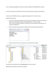
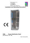
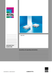
User Manual
Rittal PMC UPS 6kVA
Germany
Rittal GmbH & Co. KG
Auf dem Stützelberg
D-35745 Herborn
Tel.: ++49-27 72-5 05-0
Fax: ++49-27 72-5 05-23 19
Internet: www.rittal.de
26
Contents
1.
Introduction .................................................................................................... 29
2.
Safety Instructions.......................................................................................... 30
3.
Indicators and Operating Controls............................................................... 33
3.1
3.2
4.
Front Panel ............................................................................................... 33
Back Panel................................................................................................ 35
Installation and Start Up ............................................................................... 36
4.2
4.3
Permanently connected unit RITTAL PMC UPS 6KVA ....................... 36
Battery extension...................................................................................... 40
5.
Troubleshooting.............................................................................................. 42
6.
Maintenance.................................................................................................... 45
6.1
6.2
7.
Operation.................................................................................................. 45
Storage...................................................................................................... 45
Technical data................................................................................................. 46
7.1
Electrical specifications............................................................................ 46
7.2
Typical stored energy time (Battery mode) .............................................. 47
7.3
Dimensions and weights........................................................................... 47
7.4
Operating environment............................................................................. 47
7.5
Port connectors ......................................................................................... 48
7.5.1
RS232 interface ................................................................................ 48
7.5.2
Relay interface (Option) ................................................................... 48
8.
Appendix ......................................................................................................... 26
27
List of Figures
Figure 1: Operating and display panel...................................................................... 33
Figure 2: Slide buttons to select output voltage. ...................................................... 35
Figure 3: Attaching the stabiliser to RITTAL PMC UPS 6KVA. ............................ 37
Figure 4: Connection diagram for RITTAL PMC UPS 6KVA . .............................. 38
Figure 5: Connection of battery extensions to RITTAL PMC UPS
6kVA . ....................................................................................................... 40
Figure 6: Circuit diagram of relay interface ............................................................. 49
Figure 7: Front and back view of RITTAL PMC UPS 6KVA ................................. 51
Figure 8: Back view of battery extension for RITTAL PMC UPS
6KVA ........................................................................................................ 52
28
1. Introduction
The Rittal PMC UPS 6kVA Series is an uninterruptible power
supply incorporating double-converter technology. It provides perfect
protection specifically for Novell, Windows NT and UNIX servers.
The double-converter principle eliminates all mains power
disturbances. A rectifier converts the alternating current from the
socket outlet to direct current. This direct current charges the batteries
and powers the inverter. On the basis of this DC voltage, the inverter
generates a sinusoidal AC voltage which permanently supplies the
loads.
Computers and periphery are thus powered entirely
independently of the mains voltage. In the event of power failure, the
maintenance-free batteries power the inverter. This means an end to
the switchover times from mains to battery operation which cannot be
avoided on other systems.
29
2. Safety Instructions
PLEASE READ THROUGH AND FOLLOW THE USER
MANUAL AND THE SAFETY INSTRUCTIONS BEFORE
INSTALLING THE UNIT AND STARTING IT UP!
Transport
• Please transport the UPS system only in the original packaging (to
protect against shock and impact).
Set-up
• Condensation may occur if the UPS system is moved directly from
a cold to a warm environment. The UPS system must be absolutely
dry before being installed. Please allow an acclimatisation time of
at least two hours.
• Do not install the UPS system near water or in damp environments.
• Do not install the UPS system where it would be exposed to direct
sunlight or near heat.
• Do not block off ventilation openings in the UPS system’s housing.
Installation
• Please note the special installation aspects for the permanently
connected units Rittal PMC UPS 6kVA in Chapter 4 „Installation
and Start Up“.
• The building wiring socket outlet (shockproof socket outlet) must
be easily accessible and close to the UPS system.
30
• Please use only VDE-tested, CE-marked power cables to connect
the loads to the UPS system.
• Do not connect domestic appliances such as hair dryers to UPS
output sockets.
• Do not connect appliances or items of equipment which would
overload the UPS system (e.g. laser printers) to the UPS outlet
socket.
• Place cables in such a way that no one can step on or trip over
them.
Operation
• Do not disconnect the mains cable on the UPS system or the
building wiring socket outlet (shockproof socket outlet) during
operations since this would cancel the protective earthing of the
UPS system and of all connected loads.
• The UPS system features its own, internal current source
(batteries). The UPS output sockets may be electrically live even if
the UPS system is not connected to the building wiring socket
outlet.
• In order to fully disconnect the UPS system, first press the Standby
switch then disconnect the mains lead or, on the permanently
connected unit Rittal PMC UPS 6kVA, isolate the incoming
feeder.
• Ensure that no fluids or other foreign objects can enter the UPS
system.
Maintenance, servicing and faults
• The UPS system operates with hazardous voltages. Repairs may be
carried out only by qualified maintenance personnel.
31
• Caution - risk of electric shock. Even after the unit is disconnected
from the mains power supply (building wiring socket outlet),
components inside the UPS system are still connected to the
battery and are still electrically live and dangerous. Before carrying
out any kind of servicing and/or maintenance, disconnect the
batteries and verify that no current is present.
• Only persons adequately familiar with batteries and with the
required precautionary measures may exchange batteries and
supervise operations. Unauthorised persons must be kept well
away from the batteries.
• Caution - risk of electric shock. The battery circuit is not isolated
from the input voltage. Hazardous voltages may occur between the
battery terminals and the ground. Before touching, please verify
that no voltage is present!
• Batteries may cause electric shock and have a high short-circuit
current. Please take the precautionary measures specified below
and any other measures necessary when working with batteries:
- remove wristwatches, rings and other metal objects
- use only tools with insulated grips and handles.
• When changing batteries, install the same number and same type of
batteries.
• Do not attempt to dispose of batteries by burning them. This could
cause battery explosion.
• Do not open or destroy batteries. Escaping electrolyte can cause
injury to the skin and eyes. It may be toxic.
• Please replace the fuse only by a fuse of the same type and of the
same amperage in order to avoid fire hazards.
• Do not dismantle the UPS system.
32
3. Indicators and Operating Controls
3.1 Front Panel
Figure 1: Operating and display panel
Switch
ON - Switch
Function
1. Turn on UPS system:
By pressing the ON-Switch „I“ the UPS system is turned on.
2. Deactivate acoustic alarm:
By pressing this switch an acoustic alarm can be
deactivated.
33
StandbySwitch
The UPS system switches to Standby mode when the
Standby button „ “ is pressed. It is then switched to
Bypass and the inverter is off. The output sockets are
supplied with voltage via the bypass if the mains
power supply is available.
Display
Function
LINE LED
1. The green LINE LED lights up if mains voltage is
applied to the UPS input.
2. LINE_LED blinks when the phase and neutral
conductor have been reversed at the input of the
UPS system.
3. If LINE-LED and BATTERY-LED light up, the
mains power supply is out of tolerance.
BATTERYLED
The orange-coloured BATTERY-LED lights up when
the mains power supply has failed and the inverter is
being powered by the batteries.
BYPASSLED
The orange-coloured BYPASS LED lights up when
the UPS system is supplying voltage provided by the
mains power supply system via the bypass.
INVERTER
-LED
The green INVERTER LED lights up if the inverter of
the UPS is operating and supplying the UPS output
with energy.
FAULTLED
The red FAULT-LED lights up and an acoustic
warning signal is issued every second when the UPS is
overloaded (load exceeds the maximum power of the
UPS).
The red FAULT LED lights up and an acoustic
warning signal is issued when the UPS system is in
fault condition. Press the Standby switch in order to
turn off the warning tone.
34
35
Load and
battery
capacity
LED
1. These LEDs signal the UPS system load if the
mains power is available (normal operation):
1st LED 1-35 %
2nd LED 35-55 %
3rd LED 55-75 %
4th LED 75-95 %
5th LED 95-100 %.
2. In the case of battery operation, the LEDs indicate
the capacity of the batteries:
1st LED 1-35 %
2nd LED 35-55 %
3rd LED 55-75 %
4th LED 75-95 %
5th LED 95-100 %.
3.2 Back Panel
Slide buttons on the back panel allow selection of the outgoing
voltage of the UPS system. This can be changed only when the UPS
system is switched off.
Figure 2: Slide buttons to select output voltage.
36
4. Installation and Start Up
4.1 Permanently connected unit RITTAL PMC UPS
6kVA
The system may be installed and wired only by qualified
electricians in accordance with applicable safety regulations!
When installing the electrical wiring, please note the nominal
amperage of your incoming feeder. UPS> 6000 VA are not
suitable for 16 A sub-distribution boards!
1) Inspect the packaging carton and its contents for damage. Please
inform the transport agency immediately should you find signs of
damage.
Please keep the packaging in a safe place for future use.
2) Fit the supplied stabiliser, as shown in the illustration below,
before installation:
37
Figure 3: Attaching the stabiliser to RITTAL PMC UPS 6KVA.
The supports must be unscrewed adequately on both sides so that the
castors are not contacting the ground!
3) Please ensure that the incoming feeder is isolated and secured to
prevent it from being switched back on again. Set the I/P and the
O/P switch on the back panel to position „OFF“.
4) Connect the UPS system to the mains at the screw terminals as
shown in the diagram below:
38
Figure 4: Connection diagram for RITTAL PMC UPS 6KVA
5) Connect your computer to the screw-type terminals of the UPS
system as shown in the above diagram.
Caution!
Do not connect equipment which would overload the UPS
system (e.g. laser printers). Do not connect domestic appliances
to the UPS system.
6) Set the I/P switch on the back panel to position „ON“.
Note:
Load capacity LEDs first light up simultaneously, then one after
the other. After a few seconds the INVERTER-LED lights up and
the BYPASS-LED turns off.
7) Fully charge the batteries of the UPS system by leaving the UPS
system connected to the mains for 1-2 hours. You can also use the
39
UPS system directly without charging it but the stored energy time
may then be shorter than the nominal value specified.
8) Set the O/P switch on the back panel to position „ON“.
9) Press the On button „I“ on the front panel.
Note:
The INVERTER LED lights up after 10 seconds. The BYPASS
LED then goes out and the ventilation system switches on. The
UPS system is now operating correctly.
10)Test the function of the UPS system by either pressing the On
button „I“ or disconnecting the input of the UPS system from the
power supply.
Caution!
The output sockets of the UPS system may still be electrically
live even if the power supply system has been disconnected or if
the I/P switch is in position OFF.
40
4.2 Battery extension
External battery extensions are available for the UPS model. In order
to connect them to the UPS system, proceed as shown below:
1. Disconnect the UPS system from the mains power supply and the
load from the UPS system.
2. Connect the battery extensions to the UPS system with the
included cables according to the following instructions:
Figure 5: Connection of battery extensions to RITTAL PMC UPS 6KVA.
41
3.
The UPS system can now operate normally.
Note:
Operating the system with external battery extensions prolongs
charging to 24 hours with one battery extension and to 48 hours
with two battery extensions after total discharge.
42
5. Troubleshooting
If the UPS system does not operate correctly, please attempt to solve
the problem using the table below.
Problem
No indication,
no warning tone
even
though system
is connected to
mains power
supply
Possible cause
No input voltage
I/P switch has been
disconnected
BATTERYLED blinks
Battery voltage
< 12VDC per unit.
LINE-LED
blinks and
BATTERYLED lights up
LINE-LED and
BYPASS-LED
light up even
though the
power supply is
available
Input power and/or
frequency are out of
tolerance
Remedy
Check building wiring
socket outlet, check input
cable
Set the I/P switch to „ON“
When battery voltage >
12VDC per unit then clear
warning signal.
Check input power source
and inform dealer if
necessary
Inverter not switched
Press On button “I”
on
43
INVERTERLED lights up,
warning tone at
intervals (every
1 or 4 seconds)
INVERTER-LED
lights up, warning
tone in intervals (1
to 4 seconds),
mains power
supply available
FAULT-LED
lights up,
warning tone
once a second
FAULT-LED
lights up,
permanent
warning tone
Emergency
supply period
shorter than
nominal value
Mains power supply
has failed
Not necessary, battery
operation;
warning tone at intervals
of 1 second means battery
is almost empty
Set the I/P switch to „ON“.
If the problem persists,
please inform your dealer.
I/P switch
disconnected
Overload
Reduce number of users at
UPS output
UPS-mistake
Notify dealer!!
Batteries not fully
charged / batteries
defective
Charge the batteries for at
least 1 - 2 hours. Check
capacity. If the problem
still persists, consult your
dealer.
44
Please have the following information at hand before calling the
After-Sales Service Department:
1. Model number, serial number
2. Date on which the problem occurred
3. Detailed description of the problem
45
6. Maintenance
6.1 Operation
The UPS system contains no user-serviceable parts.
If the battery service life (3 - 5 years at 25 °C ambient temperature)
has been exceeded, the batteries must be exchanged. In this case
please contact your dealer.
6.2 Storage
If the batteries are to be stored in temperate climatic zones, they
should be charged every three months for 1-2 hours (see Chapter
"Installation and Start Up"). You should shorten the charging intervals
to two months at locations subject to high temperatures.
46
7. Technical data
7.1 Electrical specifications
6kVA
Model number
INPUT
Voltage
230 VAC (160 – 276 VAC) ± 3%
50/60 Hz ± 5 % automatic detection
29,6 A
Frequency
Current
(maximum)
OUTPUT
Power rating
Voltage
Frequency
Wave form
6000VA
4200 W
220/230/240 VAC ± 0,5% (synchronized)
50/60 Hz ± 0,5 % (free-wheeling)
Sinusoidal
BATTERIES
Number and type
20 x12V 7Ah
The units bear the CE mark and comply with the following standards
(limit value class B):
EN 60950 (1992.8),
EN 50091-1 (1994.4),
prEN 50091-3 (1994.4),
EN 50081-1 (1992.2),
EN 50082-1 (1992.2),
IEC 801-2 Level 4,
IEC 801-3 Level 3,
IEC 801-4 Level 4,
IEC 801-5 Level 2.
47
7.2 Typical stored energy time (Battery mode)
Typical values at 25°C in minutes:
Model
RITTAL PMC UPS 6KVA
RITTAL PMC UPS 6KVA + 1
battery extension
RITTAL PMC UPS 6KVA + 2
battery extensions
100 %
Load
50 % Load
8
38
23
88
60
141
7.3 Dimensions and weights
Model
RITTAL PMC
UPS 6KVA
Battery extension
for RITTAL PMC
UPS 6KVA
Dimensions
WxHxD
(mm)
Net
Weight,
kg
Gross
Weight, kg
260 x 710 x 555
91
107
260 x 710 x 555
125
145
7.4 Operating environment
Temperature:
3000 m
Relative humidity:
10 °C to 40 °C, Installation height < 1500 m
0 °C to 35 °C, Installation height 1500 m to
20 to 90 %, no condensation
48
7.5 Port connectors
A computer can be connected to the port connectors RS232 interface
on the back panel of the UPS system.This allows
• the UPS system to be monitored,
• the mains system to be monitored,
• data to be backed up,
• the computer to be switched off and
• the UPS system to be switched off.
There are various software packages for implementing these
functions. Please consult your dealer for further details.
7.5.1 RS232 interface
The 9-pin Sub-D connector (socket) makes an RS232 interface
available.
Description of the PIN assignment:
Pin
2
3
5
RXD
TXD
GND
received data
transmitted data
ground
7.5.2 Relay interface (Option)
The 9-pin Sub-D connector (socket) makes a relay interface available.
49
Figure 6: Circuit diagram of relay interface
Description of the PIN assignment:
Battery mode
Pin
No.
2
UPS shut-down
in case of
battery
operation
6, 7
Battery capacity
low
5
normally
open
normally
open
50
PIN 2 is shorted to PIN 4
(ground) if the mains power
supply fails or is out of
tolerance.
If, in the case of battery
operation, a positive signal
level (+5 V to + 12 VDC) is
applied for 500 ms, the UPS
system shuts down.
PIN 5 is shorted with respect
to PIN 4 if batteries have
become discharged to such
Normal mode
3
normally
closed
51
an extent that the remaining
emergency supply period at
full load is less than 2
minutes.
PIN 3 is shorted to PIN 4
during normal operation and
opened, if the mains power
supply fails or is out of
tolerance
8. Appendix
Figure 7: Front and back view of RITTAL PMC UPS 6KVA
52
Figure 8: Front and back view of RITTAL PMC UPS 6KVA
BatteryPack
53