1
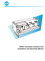
ENS31 Automatic Isolation Unit
Installation and Operating Manual
UfE Umweltfreundliche Energieanlagen GmbH
Joachim-Jungius-Straße 9
D - 18059 Rostock
Tel.:
Fax:
E-mail:
web:
+49 3 81 / 405 97 05
+49 3 81 / 405 97 03
[email protected]
www.ufegmbh.de
Note
If you have any queries and need to contact UfE GmbH, always have the
serial number close to hand in order to make reference to it. We do not claim
the documentation is free of errors and mistakes. Please inform UfE GmbH of
any errors found in the documentation.
© Copyright
This operating manual is the copyright of UfE GmbH.
This manual is intended for the operator and electrician. It contains instructions
and information which must not be copied, distributed or transferred by
technical data methods nor used for the purpose of competition, either as an
entirety or as extracts, without the necessary authorisation.
Contravention could lead to prosecution and obligation to pay damages.
All rights reserved, particularly in the case of patent application or other
registrations.
We reserve the right to make technical modifications without notice.
Note
The ENS31 isolation unit and the measuring method are protected by patent.
Page 2 of 32
Installation and Operating Manual ENS31
A.04
Declaration of Conformity
We
UfE Umweltfreundliche Energieanlagen GmbH
Joachim-Jungius-Straße 9
D - 18059 Rostock
declare in sole responsibility that the product
Type: ENS31 Automatic Isolation Unit
fulfils the applicable health and safety requirements in the EU Directives
89/336/EEC (Electromagnetic Compatibility EMC) and
73/23/EEC (low voltage guidelines)
and the law reorganising the safety of technical apparatus and consumer
products (law on equipment and product safety),
as well as the requirements stipulated in other applicable, harmonised European
Norms.
In addition, the following directive is also fulfilled:
89/391/EEC (employee safety and health protection)
Klaus-Wilhelm Köln
Manager
A.04
Installation and Operating Manual ENS31
Page 3 of 32
Table of Contents
1
Safety.................................................................................................................6
1.1
1.2
1.3
1.4
1.5
1.6
1.7
1.8
1.9
2
Connections and Indicators ..........................................................................12
2.1
2.2
3
Principles of functioning........................................................20
Function Test..................................................................................................21
6.1
6.2
7
Basic configuration ...............................................................17
Demands of the switching elements.....................................17
Circuitry ................................................................................18
Disconnection .......................................................................19
System Description........................................................................................20
5.1
6
Transport and unpacking......................................................14
Conditions for installation .....................................................14
Preparing the electrical/meter cabinet ..................................15
Mounting on the top hat rail ..................................................15
Removing from the top hat rail .............................................16
Electrical Connections...................................................................................17
4.1
4.2
4.3
4.4
5
Connections..........................................................................12
LCD display and LEDs .........................................................13
Mechanical Installation ..................................................................................14
3.1
3.2
3.3
3.4
3.5
4
General information ................................................................6
Safety symbols used in this operating manual .......................6
Obligations..............................................................................7
1.3.1.
Obligations of the proprietor ....................................7
1.3.2.
Obligation of personnel ...........................................7
Guarantee and liability............................................................8
Accident prevention regulations .............................................9
Intended use...........................................................................9
1.6.1
Exclusive purpose ...................................................9
1.6.2
Observe information and regulations ......................9
Installation and connection ...................................................10
Operation..............................................................................10
Rating plate and CE symbol .................................................11
Switching the system on.......................................................21
Indicators during operation ...................................................21
Operation ........................................................................................................22
7.1
Page 4 of 32
Switching the system on.......................................................22
Installation and Operating Manual ENS31
A.04
Table of Contents
7.2
7.3
7.4
8
LED indicators during the power-on routine .........................23
LCD displays during operation..............................................23
Switching the system off .......................................................25
Troubleshooting .............................................................................................26
8.1
8.2
General information ..............................................................26
Error indications in the LCD..................................................26
8.2.1
Error status for voltage ..........................................26
8.2.2
Error status for frequency ......................................26
8.2.3
Error status for phase angle ..................................27
8.2.4
Error status for impedance ....................................27
8.2.5
Faults in the ENS 31 isolation unit.........................27
8.2.6
Error texts for mains power fluctuations ................28
8.2.7
Hardware Errors ENS31 ........................................29
8.2.8
Error indication through LEDs ...............................30
9
Technical Data ................................................................................................31
10
Certificate of Non-Objection..........................................................................32
A.04
Installation and Operating Manual ENS31
Page 5 of 32
Chapter 1
Safety
1
1.1
Safety
General information
This chapter contains information on safety and rules of conduct. It is essential
to observe the information and rules so that any residual risks represented by the
product do not lead to a fault or an accident.
The device must be connected to the local power supply. Therefore, all the
normal risks involved in the use of electrical power are present here, too.
1.2
Safety symbols used in this operating manual
The following symbols are used at the relevant points throughout this manual.
Pay strict attention to the information provided in these sections and proceed
with the utmost care.
Meaning of the safety symbols:
Danger
This symbol indicates the risk of fatal or personal injury if certain rules of
conduct are disregarded. When this symbol appears in the operating
manual, take all the necessary safety precautions.
Attention
This symbol indicates the risk of property damage as well as financial and
legal disadvantages (e.g. loss of rights to claims under the terms of
guarantee, liability, etc.).
Note
This symbol indicates important information on working efficiently,
economically and ecologically.
Page 6 of 32
Installation and Operating Manual ENS31
A.04
Chapter 1
Safety
1.3
1.3.1.
Obligations
Obligations of the proprietor
The proprietor is obliged only to allow suitably trained personnel to work with
the ENS31 isolation unit who
• are familiar with the basic regulations on safety and accident prevention
• have read the operating manual, the chapter on safety and the safety
symbols, have understood them and confirmed this with their signature.
The proprietor must always ensure the entire product documentation is at the
disposal of operating personnel.
Danger
The proprietor bears the responsibility for safety. This responsibility cannot
be delegated.
1.3.2.
Obligation of personnel
Personnel must:
• be in possession of a license to connect electronic equipment to the public
electricity supply,
• always ensure for themselves that third-parties and the equipment are safe,
• maintain the safety and connection regulations of the power supply provider,
• have read and understood the operating instructions, the chapter on safety
and warning labels,
• observe the applicable regulations concerning industrial safety and accident
prevention.
Danger
This concerns the safety of yourself and other persons in the vicinity of the
ENS31 as well as safety when working with the mains electricity supply.
A.04
Installation and Operating Manual ENS31
Page 7 of 32
Chapter 1
Safety
1.4
Guarantee and liability
Our "General Terms of Sale and Delivery" apply. The proprietor has claim to
these on conclusion of the contract at the latest. Rights to claims under the terms
of guarantee and liability in respect of persons and property are considered void
when they are the result of one or more of the following causes:
• Unintended use of the ENS31,
• Improper start up, operation and service of the ENS31,
• Failure to observe information in the overall documentation in respect of
–
–
–
–
•
•
•
installation, connection
starting up
operation
cleaning/servicing
Unauthorised constructional modifications to the ENS31,
Damage through overvoltage, overload, short circuit, mechanical
interference, moisture,
Case of catastrophe caused by foreign body or Act of God.
Attention
No modification may be carried out on the ENS31 without the approval of the
manufacturer.
Attention
Never attempt to repair the device yourself. All rights to claims under the
terms of guarantee are annulled in the case of tampering.
Page 8 of 32
Installation and Operating Manual ENS31
A.04
Chapter 1
Safety
1.5
Accident prevention regulations
Any faults which occur that affect safety must be eliminated immediately. The
ENS31 may not be operated until the fault has been cleared.
Danger
Solar modules conduct electricity as soon as they are exposed to daylight.
Observe this when laying and connecting the cables and take the necessary
precautions.
Danger
It is forbidden to open the unit. The box can continue to conduct dangerous
residual voltage some minutes after being switched off.
1.6
Intended use
The ENS31 has been built according to state-of-the-art technology and accepted
safety regulations.
However, when the unit is used, there remains a risk of fatal and personal injury
to the user and third-parties as well as impairment of the unit and other property
damage.
1.6.1
Exclusive purpose
The ENS31 is exclusively intended for monitoring voltage, frequency and
impedance of the electricity network at the feeding point of a power generating
system. On detecting over- and undervoltages, frequency deviation or
impedance jumps, the ENS31 disconnects the feeding point from the public
electricity supply by means of contactors.
Any other use is considered unintended use. The manufacturer is not liable for
any consequential damage in such cases.
1.6.2
Observe information and regulations
Intended use also includes
• observing all information provided in this operating manual and
• maintaining the connection and installation conditions prescribed by the
manufacturer.
A.04
Installation and Operating Manual ENS31
Page 9 of 32
Chapter 1
Safety
1.7
Installation and connection
For installation and connection of the ENS31 please observe chapters 2 to 5.
Danger
It is forbidden to open the unit. The unit can continue to conduct dangerous
residual voltage some minutes after being switched off.
1.8
Operation
Operation of the ENS31 is impermissible:
• for monitoring tasks for which the unit is not designed,
• when using accessories which have not been approved by the manufacturer,
• when the proprietor has made constructional modifications.
Functional faults must be analysed immediately. If necessary, the proprietor
must request specialist assistance. The equipment may only be put into
operation again when there is no doubt about its safety.
The ENS31 is intended for operation at room temperatures between
- 20 °C and + 40 °C (also refer to Chapter 9).
Contact a suitably trained electrician or the manufacturer in the following cases:
• connection cable is damaged,
• liquids or foreign bodies have got inside the unit,
• the unit has been exposed to water or rain,
• the unit has fallen down or is mechanically damaged,
• the unit behaves in a way indicating a fault (e.g. indicator on the LCD,
constant switching).
Page 10 of 32
Installation and Operating Manual ENS31
A.04
Chapter 1
Safety
1.9
Rating plate and CE symbol
The manufacturer has provided the following information on the ENS31 at the
positions indicated:
A
B
A Serial number
The manufacturer’s serial number for the ENS31 is provided at this point.
B CE-symbol
The CE symbol is located at the bottom right corner of the front side.
Note
Always make reference to the ENS31 serial number in the case of inquiries,
orders and contracts. This simplifies communication with the manufacturer
and prevents errors when processing requests.
A.04
Installation and Operating Manual ENS31
Page 11 of 32
Chapter 2
Connections and Indicators
2
2.1
Connections and Indicators
Connections
The following connections are provided at the top edge of the ENS31:
<RELAIS
<KONTAKTE
1 2 3 4
<NETZ
N L1 L2 L3
1 2
A
B
C
A 4 connection terminals for contactor control, potential-free;
designation from left to right: R1, R2, R3 and R4
B 2 connection terminals to connect positively driven auxiliary contacts;
designation from left to right: K1 and K2
C 4 connection terminals to connect three phases and the neutral
conductor; designation from left to right: N, L1, L2 and L3
Page 12 of 32
Installation and Operating Manual ENS31
A.04
Chapter 2
Connections and Indicators
2.2
LCD display and LEDs
The following indicators are mounted on the front side of the ENS31:
X XXXXX
A
B
C
D
A LCD display
The unit and mains power status are shown on a 2-line LC display. Each line
can display 16 characters.
B to D LEDs
In addition to the LCD, the unit and mains power status are also indicated by
three LEDs (red, green, yellow):
B = LED display for phase 1 (L1)
C = LED display for phase 2 (L2)
D = LED display for phase 2 (L3).
Note
The meaning of the indicators is described in chapter 7 and chapter 8.
A.04
Installation and Operating Manual ENS31
Page 13 of 32
Chapter 3
Mechanical Installation
3
3.1
Mechanical Installation
Transport and unpacking
When transporting the ENS31 isolation unit, pay attention that it is always
protected against contact with dirt and damage through impacts and setting
down too hard.
Remove the ENS31 from the transport packaging and pull off the protective
foil, if necessary.
After transport and before installation, check that the ENS31 isolation unit is in
a perfect condition.
3.2
Conditions for installation
The ENS31 is intended for installation on a top hat rail in an electrical cabinet
or in a meter cabinet. It cannot be installed anywhere.
The cabinet must be sufficiently large to house the ENS31, providing the
necessary contactors and protect the unit from moisture, dust, dirt and heat.
If there is not enough space in the cabinets available, a separate electrical
cabinet must be mounted to accommodate the ENS31 and contactors.
Attention
Never position the electrical cabinet containing the ENS31 above or in the
vicinity of a heater. Ensure sufficient ventilation.
The ENS31 should be mounted as near as possible to the mains power outlet
and as far as possible from the electricity feeding source.
Note
These measures reduce the effect of voltage increase by the current source.
Page 14 of 32
Installation and Operating Manual ENS31
A.04
Chapter 3
Mechanical Installation
3.3
Preparing the electrical/meter cabinet
Determine the installation position of the ENS31 on the top hat rail.
Saw a cut-out in the cabinet cover at the installation position of the ENS31 so
that you can see the ENS31 and its indicators (LCD and LEDs) without opening
the cabinet.
The cut-out must have the following dimensions:
219 mm
74 mm
X XXXXX
3.4
Mounting on the top hat rail
Set the isolation unit with its top housing holder (A) on the top hat rail and turn
it downwards against the top hat rail (B). Use a little force to press on the
bottom housing section until the housing holder engages in the top hat rail.
A
B
A.04
Installation and Operating Manual ENS31
Page 15 of 32
Chapter 3
Mechanical Installation
3.5
Removing from the top hat rail
The ENS31 can be removed from the top hat rail.
Insert the tip of a screwdriver in the grooves (A) in the clamps at the ends of the
housing. Pull the clamps downwards (B). The ENS31 is released. Remove the
ENS31 by turning it a little (C) away from the top hat rail.
C
A
B
Attention
Never remove the ENS31 from the top hat rail using brute force. This could
damage the housing holders.
Page 16 of 32
Installation and Operating Manual ENS31
A.04
Chapter 4
Electrical Connections
4
4.1
Electrical Connections
Basic configuration
The switching elements of the automatic isolating device (e.g. contactors) are
not enclosed with the unit and must be brought by the installation technician.
The technician decides on the switching elements most suitable.
Danger
The installation technician must ensure that the power generator is only
connected to the mains via the two switching elements assigned to the ENS.
Risk of accident!
The ENS31 must be protected by pre-fuses in the mains feed circuit (min. 6 A,
max. 25 A). Observe the circuit diagram.
4.2
Demands of the switching elements
Two contactors with positively driven auxiliary contacts are required for mains
disconnection. The feedback contacts must be connected in the correct sequence
(refer to circuit diagram).
The contactors must be designed for the nominal output of the current inverter
or the system at AC3. The decisive factor for dimensioning is the phase with the
highest load.
A.04
Installation and Operating Manual ENS31
Page 17 of 32
Chapter 4
Electrical Connections
4.3
Circuitry
N
1
2
1
2
3
4
3
4
5
6
5
6
L1
L2
L3
MAINS
FEEDER
Check that the mains power lines and power feed lines are not conducting
electricity.
Switch the power generator (feeder), ENS31 and contactors as follows (note the
turning direction):
21
-K10.1
22
21
-K10.2
22
-K10.1
-K10.2
A1
R1R2R3R4
RELAY
A2
A1
* * *min. 6 A
max. 25 A
A2
K1 K2
CONTACTS
N L1 L2 L3
MAINS
UfE - ENS31
Note
The additional pre-fuse (*) is only necessary if the direct mains power fuse
protection exceeds 25 A.
The terminals on the ENS31 are arranged as follows:
relay
contacts
mains
Page 18 of 32
Installation and Operating Manual ENS31
A.04
Chapter 4
Electrical Connections
Attention
The ground conductor should always bypass the unit. The neutral conductor
MUST be connected to the ENS31 otherwise the unit may be damaged.
If the ENS31 is switched on and off by means of a system control unit, the L1
connection of the ENS31 can be switched by means of a relay.
Note
When switching on via L1, the delay until the contactors are activated can be
up to 30 seconds because the ENS31 must test the power feed conditions
again.
4.4
Disconnection
Switch off the power supply to the mains power lines and lines from the power
generator (feeder).
Wait until the isolation unit has removed all the residual voltages.
Danger
The isolation unit can still conduct dangerously high residual voltage some
minutes after being switched off. Risk of accident!
Disconnect the mains power lines, contactor lines and relay lines.
Insulate bare contacts from mains power lines, contactor lines and relays (e.g.
using insulation tape).
The ENS31 can then be removed from the top hat rail (also refer to Chapter
3.5).
A.04
Installation and Operating Manual ENS31
Page 19 of 32
Chapter 5
System Description
5
5.1
System Description
Principles of functioning
The automatic, three-phase ENS31 isolation unit is an automatic switch which
is used to connect decentralised electricity generators to the public electricity
supply.
In the event of faults in the mains supply, the ENS31 interrupts the feeding of
electricity into the mains to prevent an island effect.
The following deviations are monitored:
• overvoltage and undervoltage
• frequency deviation
• impedance jumps
The isolation unit replaces an otherwise prescribed manual isolation unit to
which the power supply authorities must have permanent access.
Note
Further information on the principles of functioning is available on our
Internet site at www.ufegmbh.de.
Page 20 of 32
Installation and Operating Manual ENS31
A.04
Chapter 6
Function Test
6
6.1
Function Test
Switching the system on
Switch the isolation unit on first and then the power generator (feeder).
The ENS starts up automatically after switching on the mains supply.
The following appears on the LCD display after a successful self-test and mains
test:
D 231 232 233 V
Ok 50,00 120 240
When the voltage, frequency and mains impedance are in the permissible range
for 20 seconds, the contactors are triggered and power feed in the public
electricity supply begins. The mains power is then monitored.
6.2
Indicators during operation
After switching on, the values for voltage, impedance and frequency are
displayed alternately (refer to chapter 7).
A.04
Installation and Operating Manual ENS31
Page 21 of 32
Chapter 7
Operation
7
7.1
Operation
Switching the system on
The LCD indicates the status of the power-on routine:
D 231 232 233 V
Ok 50,00 120 240
The first character indicates the status of the ENS. The following states can
occur during the power-on routine:
Indicator
Meaning
i
Following a reset, the ENS31 is in its initialised state.
w
After initialisation, all the error bits are deleted and the system
waits a fixed time.
r
The ENS31 is waiting for a return signal.
^
The ENS31 switches on after the waiting period.
D
The ENS31 is switched on, the mains power is within a
F
permissible range and power is fed. The mains power is
I
monitored constantly. The letters indicate: D = Setting for
Germany, Austria and Switzerland, F = Setting for France, I =
Setting for Italy.
X
The ENS31 has interrupted power feed.
Page 22 of 32
Installation and Operating Manual ENS31
A.04
Chapter 7
Operation
7.2
LED indicators during the power-on routine
LEDs are provided for each individual phase and light up as follows during the
power-on routine:
Indicator
Meaning
All LEDs light up to begin with.
After approx. 1 sec., a running light is activated.
The mains power is in order and the ENS31 switches it on.
During operation, the yellow LED can flash or light up
continually.
7.3
LCD displays during operation
The LCD runs through the following display modes cyclically:
First display
Error status, mains voltages, power-on routines since last rest, mains frequency,
phase angle and error messages.
A
B
C
D 231 232 233 V
Ok 50,00 120 240
F
E
D
Indicator
A.04
Meaning
A
Country identification plus error status.
Country identification letters signify the following:
D = Setting for Germany, Austria and Switzerland,
F = Setting for France, I = Setting for Italy.
B
Mains voltage of the individual phases plus error status.
L1 = left, L2 = middle, L3 = right.
C
D
Number of power-ons since the last reset.
E
F
Mains frequency and error status.
Phase angle plus error status.
The phase angle L1-L3 is to the right, phase angle L1-L2 is to
the left.
Mains power status ok.
Installation and Operating Manual ENS31
Page 23 of 32
Chapter 7
Operation
Second display
Data from the 10-minute average values.
A
Ua: 231 232 233V
Ul: 252V
B
Indicator
Meaning
A
10-minute average value of voltages plus error status.
L1 = left, L2 = middle, L3 = right.
B
Upper shutdown threshold for the 10-minute average value.
Third to fifth display
Impedances of the three phases and shutdown thresholds.
A
B
C
D
Z1= 0,44 24P 97%
-0,20 0,03 0,20
G
Indicator
A
B
C
D
E
F
G
Page 24 of 32
F
E
Meaning
Phase identification (L1, L2 or L3) and error status.
Estimated value for absolute impedance of this phase.
Number of measuring pulses per second.
Own share of the ENS31 in the total measuring signal.
Dynamic upper shutdown threshold for the impedance jump.
Last established impedance jump.
Dynamic lower shutdown threshold for the impedance jump.
Installation and Operating Manual ENS31
A.04
Chapter 7
Operation
Sixth display
Last error which occurred, information is lost following ENS reset.
A
B
C
1d ago 30 s 2
P2:ZToHi R= 9.20
E
D
Indicator
Meaning
A
Time since last error (s = seconds, m = minutes,
h = hours, d = days, w = weeks, a = years)
B
Duration of last error (s = seconds, m = minutes,
h = hours, d = days, w = weeks, a = years)
C
D
E
Power-on routines since last reset.
Error text (also refer to Chapter 8)
Error value (in the example: the impedance of 9.2 ohm was
too high on phase 2)
If hardware or impedance errors occur, the bottom line of the first display
contains an error text.
Note
The meaning of the error texts and error status displays are described in
Chapter 8.
Attention
Check the functionality of the ENS31 regularly. If, for example, a red LED
lights up constantly, the ENS31 may be defective and no power is fed in (also
refer to Chapter 8).
7.4
Switching the system off
The ENS31 cannot be switched off. The unit switches to an idling state if no
voltage is supplied. It resumes its tasks as soon as sufficient power is available.
A.04
Installation and Operating Manual ENS31
Page 25 of 32
Chapter 8
Troubleshooting
8
8.1
Troubleshooting
General information
In the case of repeated problems with the mains supply (e.g. frequent
deactivation due to mains overvoltage or undervoltage), contact the public
electricity supply authority and have the mains power quality checked at the
feeding point.
A frequent disconnection from the mains power supply can be observed
particularly in rural areas and areas with strong power fluctuations due to the
proximity of industrial plants.
8.2
8.2.1
Error indications in the LCD
Error status for voltage
LCD indication
Cause
^250
Overvoltage
v150
Undervoltage
/280
Undervoltage in the
case of fast shutdown
Undervoltage in the
_130
case of fast shutdown
Overvoltage in 10M250
minute average value
8.2.2
Recommended action
If the mains power fluctuations
occur frequently, contact your
public electricity supply
authority.
Error status for frequency
LCD indication
Cause
^50,90
Frequency is too high
Frequency is too low
v48,00
Frequency jump was
j48,00
detected (RoCoF)
Page 26 of 32
Recommended action
If the mains power fluctuations
occur frequently, contact your
public electricity supply
authority.
Installation and Operating Manual ENS31
A.04
Chapter 8
Troubleshooting
8.2.3
Error status for phase angle
LCD indication
Cause
!170
Phase angle deviates
too far from setpoint.
!240!120
8.2.4
Wrong direction of
rotation of mains.
Swap phases L1 and L2 at the
connection terminals.
Error status for impedance
LCD indication
Cause
^ 9,25
Impedance is
implausibly too high.
Impedance is
v -0,99
implausibly too low
(negative).
Impedance jumps have
n 0,33
been detected.
p 0,44
8.2.5
Recommended action
If the mains power fluctuations
occur frequently, contact your
public electricity supply
authority.
Recommended action
If the mains power fluctuations
occur frequently, contact your
public electricity supply
authority.
Faults in the ENS 31 isolation unit
In the event of errors, the following text appears in the bottom line of the first or
sixth display:
LCD indication
HRD1Err###
HRD2Err###
HRD3Err###
TMRErr###
Cause
A measuring error or hardware error has caused in the
ENS31 has caused a shutdown. The 3 digits (###) are
error codes for reference by the manufacture. If the
error occurs only briefly, it is probably due to a
measuring error. If the ENS31 does not switch on at all,
it must be replaced.
Note
The ENS31 cannot be repaired on site. Please inform the specialist workshop
that a replacement is required.
A.04
Installation and Operating Manual ENS31
Page 27 of 32
Chapter 8
Troubleshooting
8.2.6
Error texts for mains power fluctuations
In the event of a power fluctuation, one of the following texts appears in the
bottom line of the first or sixth display:
LCD indication
P* : ZPJp dR= 1.20
P* : ZNJp dR=-1.20
P* : ZToHi R= 9.20
P* : ZToLo R=-0,99
P* : FToHi F=50.83
P* : FToLo F=46.83
P* : FrqJp dF=-600
P* : F Pha2 W=180°
P* : F Pha2 W=200°
P* : F Pha2 W=664°
P* : UTHi Ua=260.0
An impedance jump has been detected.
The impedance is too high or too low.
The impedance is too high or too low.
Shutdown following RoCoF, value in mHz/s
Shutdown due to too great a phase angle
deviation
Phase L2/L3 inerchanged
The mains voltage is too high, response time
10 minutes.
P* : UToHi U=265.3
P* : UToLo U=130.4
The mains voltage is too high or too low,
response time 200 ms.
P* : UTHi Uf=310.0
P* : UTLo Uf=120.3
The mains voltage is too high or too low,
response time 20 ms, fast shutdown to
protect unit
•
Page 28 of 32
Meaning
stands for 1, 2 or 3 and indicates the phase affected L1, L2 or L3
Installation and Operating Manual ENS31
A.04
Chapter 8
Troubleshooting
8.2.7
Hardware Errors ENS31
Wiring faults / Contactors
HRD1
LCD indication
Meaning
HRD1 01 00 00 NC contact of contactor 1
is open bevor contactor 1
is activated.
HRD1 02 00 00 NC contact of contactor 2
is open bevor contactor 2
is activated.
HRD1 04 00 00 Contactor 1 activates
even with missing
enabling signal
HRD1 08 00 00 NC contact of contactor 1
does not open even if
contactor 1 is activated
Cause
NC contact not connected
according to item 4.3.
NC contact not connected
according to item 4.3.
Enabling defective / contactor
incorrectly wired
Contactor 1 does not operate /
contactor incorrectly wired,
NC contact not correctly
connected, NC contact
interchanged
HRD1 40 00 00
Contactor 2 activates
even with missing
enabling signal
Enabling defective / contactor
incorrectly wired
HRD1 80 00 00
NC contact of contactor 2 Contactor 2 does not operate /
does not open even if
contactor incorrectly wired,
contactor 2 is activated
NC contact not correctly
connected, NC contact
interchanged
HRD2
LCD indication
A.04
Meaning
Cause
HRD2 01 00 00
Contactor 1 deactivates
with valid input signal
Contactor 1 faulty
HRD2 02 00 00
Contactor 2 deactivates
with valid input signal,
NC contact 2 opens with
contactor 1 activated.
Contactor 2 faulty,
NC contact interchanged,
one contactor controls both
signal inputs.
Installation and Operating Manual ENS31
Page 29 of 32
Chapter 8
Troubleshooting
8.2.8
Error indication through LEDs
LED indication
Cause
Recommended action
Frequency error
Red lights up, green
flashes
Voltage error
Red and green flash
simultaneously
Impedance error
Red and green flash
alternately
Wait until the mains is
switched on again.
Contact the pubic
electricity authority in the
case of longer power
failures.
Measured value(s)
Mains power is ok.
outside the factory
Green lights up with short tolerance
interruptions
ENS31 waiting for
Mains power is ok.
acknowledgement
from inverse rectifier
Green flashes rapidly
Display of impedance jump threshold value:
lights up briefly = 0.1 ohm
lights up longer = 0.5 ohm.
or
short, short, long = 0.1 + 0.1 + 0.5 = 0.7 Ohm
LED continually on: threshold is set to 1 ohm or
more.
Measuring error or
If the LED lights up
ENS31 has failed
longer than 1 minute with
mains available, the
Red lights up
ENS31 is defective. Have
the ENS31 replaced by a
specialist workshop.
Page 30 of 32
Installation and Operating Manual ENS31
A.04
Chapter 9
Technical Data
9
Technical Data
Switched power (max.)
Dependent on the contactors
assigned
Own consumption
Housing
3.5 W
Overall dimensions (W x H x D)
220 mm x 111 mm x 80 mm
Cut-out dimensions (W x H)
220 mm x 73 mm
Plastic, suitable for assembly on the
top hat rail
- 20 °C to + 40 °C,
10 to 90 % relative humidity, noncondensating
According to max. switching
Nominal current of power feeder
power of the contactors
The unit disconnects the mains under the following defined conditions
(complying with standard DIN VDE 0126):
> 300 V (response time 0.02 s)
Overvoltage
(fast shutdown)
> 264 V (response time 0.2 s)
Overvoltage
230 V + 10% over 10 minutes
Overvoltage (average)
< 130 V (response time 0.02 s)
Undervoltage
(fast shutdown)
< 185 V (response time 0.2 s)
Undervoltage
+ 0,2 Hz / -2,5 Hz
Frequency deviation
(response time 0.2 s)
> 0.5 Ohm (response time 0.5 s)
Impedance jump detection
Ambient conditions
A.04
Installation and Operating Manual ENS31
Page 31 of 32