1
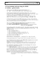
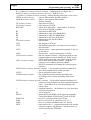
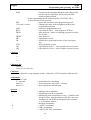
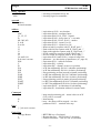
Stögra
SERS
SERS Parameter
Option Pulse Input / Electrical Gearing Function / Hand wheel /
Encoder input / Load angle control with correction of position /
Frequency measurement
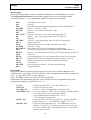
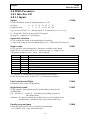
P1143
0 : function disabled
1 : Pulses at digital input I 3 result in moving motor (stepper driver clock input)
2 : as 1, but additionally with direction at digital input I 4 (aktive = negative direction)
3 : Pulses at digital input I 3 result in moving into positive direction
Pulses at digital input I 4 result in moving into negative direction
4 : Load angle control - connection of a 2-channel-encoder :
Channel A at digital input I 3 and channel B at digital input I 4
(P1002: if the max. load angle - saved into P1057 - exceeds the value in P1002,
then a load angle error will be created – depending on P1029)
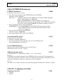
5 : Pulses at digital input I 3 are measured as frequency (result in P1146)
Scaling factor input pulses
P1144
Definitions as P1054, but regarding to P1143 (pulses at I 3 and I 4)
Time slot for frequency measuring
P1145
Definition wie P1055, aber bezogen auf P1143 (Pulse an I 3 und I 4)
Frequency at P1143=5
P1146
Frequency at P1143=5
Unit: Pulses / P1145 (time slot)
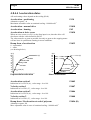
Pulse input counter 3
P1147
Used internally and should not be written!
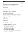
Reading out or erasing pulse input counter 3 (encoder interface with option “E50“).
In case of writing P1147 an electrical gearing function (at P1053=7) may receive new
command values, what results in a not planned drive reactions (movements).
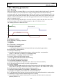
Keep absolute value in case of error limit switch
and function electrical shaft / handwheel
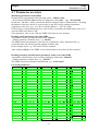
P1094
In cese of P1053=3 or P1053=7 if the motor moves on a limit switch (when
controled by the external encoder signals), then the drive will be stopped and the motor phase
current will be switched off. If afterwards the external encoder signals are into the opposite
direction, then depending on P1094 the motor reacts as follows:
0 : encoder signals into the direction of the open limit switch will be ignored. Encoder signals
into the opposite direction result in switching on the phase current and following of the
motor to the encoder signals.
1 : encoder signals, into the direction of the open limit switch are not executed, , but will be
counted internally (increment the counter). Encoder signals into the opposite direction
result in dercrementing the internal counter . If the counter is ‘0’, then the motor phase
current will be switched on and the motor follows the encoder signals. So the motor
position is allways identically (proportionally) to the position of the handwheel (or leading
axis in case of encoder signals from an other ‘leading’ motor).
- 69 -