1
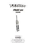
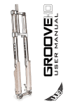
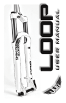
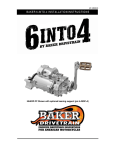
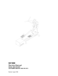
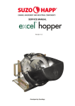
O W N E R S MA N UA L F O R
580 N. Westgate Dr.
Grand Junction, CO 81505 USA
1.800.999.8277
www.whitebrotherscycling.com
A division of
PAGE 1
TABLE OF CONTENTS
SAFETY.......................................................PAGE 2
INTRODUCTION........................................PAGE 2
FORK INSTALLATION..............................PAGE 3
TUNING.......................................................PAGE 4
MAINTENANCE........................................PAGE 5
TROUBLE SHOOTING..... ........................PAGE 6
EXPLODED VIEWS.............................PAGE 7,8,9
WARRANTY..............................................PAGE 10
IMPORTANT
CONSUMER SAFETY INFORMATION
WARNING: RIDING A BIKE IS DANGEROUS. NOT PROPERLY MAINTAINING OR INSPECTING YOUR BIKE AND
IT’S COMPONENTS IS EVEN MORE DANGEROUS. IT IS ALSO DANGEROUS TO NOT READ AND FOLLOW
THESE INSTRUCTIONS.
1. NEVER REMOVE STEERER TUBE FROM CROWN. THIS IS A PRESSED IN PART. REMOVING IT WILL
RENDER BOTH THE CROWN AND STEERER TUBE INOPERABLE.* MAKE SURE THE FORK CAPS AND ALL
FORK HARDWARE (pinch bolts, etc.) ARE TIGHT BEFORE EACH RIDE.
2. DO NOT PERFORM ANY MODIFICATIONS OR ADJUSTMENTS THAT ARE NOT OUTLINED IN THIS
MANUAL. SEE THE TUNING SECTION FOR MORE DETAILS.
3. INSPECT YOUR FORK BEFORE EVERY RIDE. INSPECT THE CROWN, TUBES, AND AXLE SEAT AREAS FOR
ANY SIGNS OF FATIGUE, BENDING, CRACKING OR OTHER DAMAGE. IF YOU NOTICE ANY TYPE OF
DAMAGE, DO NOT RIDE IT. RETURN IT TO YOUR DEALER OR TO WHITE BROTHERS FOR A COMPLETE
INSPECTION AND NECESSARY REPAIR.
4. THIS WHITE BROTHERS FORK IS DESIGNED WITH A LOCKOUT THAT TURNS OFF THE FORK’S
SUSPENSION. THE LOCKOUT IS ONLY DESIGNED TO BE USED ON SMOOTH TERRAIN. USING THE
LOCKOUT ON ROUGH TERRAIN, BUMPS OR DROP-OFFS CAN CAUSE SERIOUS DAMAGE TO THE FORK
AND COULD CAUSE SERIOUS PERSONAL INJURY OR DEATH.
5. PERFORM ALL RECOMMENDED MAINTENANCE ACCORDING TO THE MAINTENANCE SECTION OF THIS
MANUAL. FAILURE TO PERFORM MAINTENANCE COULD DRASTICALLY REDUCE THE FORK’S LIFE,
PERFORMANCE AND CAUSE YOUR FORK TO BE A SAFETY HAZARD.
6. WHITE BROTHERS RECOMMENDS THAT YOU WEAR PROPER SAFETY EQUIPMENT EVERY TIME YOU
RIDE, INCLUDING AN APPROVED BICYCLE HELMET. NEVER RIDE AT NIGHT WITHOUT LIGHTS.
7. ALWAYS USE GENUINE WHITE BROTHERS PARTS. USE OF AFTERMARKET REPLACEMENT PARTS AND
UPGRADES VOIDS THE WARRANTY AND COULD CAUSE STRUCTURAL FAILURE.
8.WHITE BROTHERS FORKS ARE DESIGNED FOR OFF ROAD USE ONLY. THEY ARE NOT EQUIPPED WITH
REFLECTORS FOR ROAD USE. IF YOU ARE GOING TO USE YOUR FORK ON THE ROAD, HAVE A DEALER
OR MECHANIC INSTALL REFLECTORS THAT MEET THE CONSUMER PRODUCT SAFETY COMMISSION’S
REQUIREMENTS.
*IF SERVICE BECOMES NECESSARY OR REMOVAL OCCURS, PLEASE CALL WHITE BROTHERS CUSTOMER SERVICE FOR PRODUCT
EVALUATION AND DIAGNOSIS.
INTRODUCTION
Thank you for purchasing your new White Brothers fork. Our forks are designed to help you perform at your absolute peak.
Your new White Brothers fork has oil damping and is air sprung for light weight performance. The air spring and damper is
set stock to satisfy a wide range of rider weights and riding styles. Fine tuning can be easily accomplished by changing air
pressure in the air spring cartridge. See the adjustment and maintenance section for rider weight verses air pressures settings.
For very heavy or very light riders the external damper can be adjusted to give a wide range of compression and rebound
damping. Steering accuracy is improved over conventional MTB forks by utilizing superior materials and design. These
include oversized 32mm fork tubes, a torsion box design steering crown with pressed in tubes, a one piece billet brake arch
and extra thick drop-outs. The WB forks bootless design allows a considerable amount more slider/stanchion overlap than
competitor forks which increases the fork steering accuracy. Fork travel has been chosen to offer the best performance
possible for each fork’s intended use. To ensure peak performance, proper installation and periodic maintenance is required.
When riding on public land, please respect the rights of others and stay on established paths and trails. By riding responsibly,
you are helping ensure the future of our sport.
PAGE 2
FORK INSTALLATION
White Brothers forks feature a 1-1/8” threadless steer tube. If you have a threaded type fork on your bicycle, consult
your dealer for the appropriate upgrade parts necessary to convert to a 1-1/8” threadless steer tube.
1. Remove your old fork from the bicycle. Measure the diameter and length of your old forks steerer tube to ensure
that the White Brothers steerer tube is the correct diameter and sufficient length for the installation.
2. Remove the crown race from your old fork.
3. Press the crown race onto your new White Brothers fork.(see Figure #1)
4. Preassemble the headset by sliding the fork steerer tube through the bearings. Then install the headset upper race,
headset spacer (optional), and stem onto the fork steerer tube. Adjust with optional spacers to your preferred height.
(See Figure #2) Refer to the head set owner’s manual if there are any questions about the pre-assembly.
5. Mark the steerer tube at the top of the stem. The steerer tube will now need to be cut to the correct length.
Disassemble and cut 3mm (1/8”) below the mark. Consult your dealer or mechanic if you don’t have the proper
tools to cut the steer tube.
6. The star fangled nut must now be installed into the steer tube. If you don’t have the set tool, we recommend dealer
installation of this part. (See Figure #3)
7. Clean and grease all headset bearings and races to prepare them for assembly. Note: Replace the bearings if there
is any sign of wear or corrosion.
8. Now loosely assemble the headset, stem and handle bars as done in step four.
9. Install the headset top cap into the star fangled nut. Tighten until there is no play in the steering. The fork should
rotate freely in the head tube. Straighten the stem in relation to the front tire and tighten the pinch bolts on the stem.
If there are any questions consult your dealer or mechanic.
10. Install your front brake and adjust according to the manufacture’s instructions.
11. Adjust the quick release on the hub to clear the secondary catches on the drop-outs. Tighten the quick release after
the axle is properly seated in the drop-out. Ensure that there is sufficient thread engagement (5 or more threads with
the quick release in the lock position) due to the thicker White Brothers drop-outs. Install the front wheel per
manufactures specifications.
12. Check to see that the brakes are adjusted and properly working. Make sure that the brake cable does not interfere
with any part of the bike when the fork is compressed and released.
Warning: When installing the wheel or a new tire, check for minimum clearance. Measure from the highest point on
the tire to the under side of the crown. There must be 1/8” or 3mm more clearance than the fork’s travel to ensure
adequate clearance in all riding conditions. Any less clearance can result in the tire hitting the crown resulting in
serious injury or death.
Optional Headset Spacer
Steering Stem
Star Fangled Nut
Headset Upper Race
Steerer Tube
Frame with
Headset Cups
Headset Lower Race
Fork Crown
Figure #1
Figure #2
Figure #3
PAGE 3
TUNING
To get the most out of your White Brothers fork, it is important that you tune the fork to
fit your weight, riding style and the terrain you ride.
INITIAL BREAK-IN PERIOD
Your new fork is designed to break-in over a period of 10 hours or more of riding. As
all the parts bed into each other, the stiction (friction) of the fork decreases and the
sensitivity increases. After the initial brake-in period, fine tuning the air pressure and
damping adjustments may be beneficial to achieve the best possible performance.
TOOLS NEEDED:
High pressure air pump
15/16” socket with ratchet.
6mm Allen wrench
Air Spring
Lockout /
Compression Adjuster
AIR SPRING /CARTRIDGE DAMPER
Your new White Brothers fork is designed with an air cartridge for air sprung support. An air
cartridge is a light weight, adjustable air sprung shock absorber, which screws into the fork
stanchion at the crown. The following guidelines for checking and adjusting your cartridge
will enable you to enjoy maximum performance from your fork.
1. First, test ride the fork over easy terrain. If after riding the fork over varied terrain you
decide that more tuning is necessary, continue to the next step.
2. The compression or spring of the fork can be changed two ways: 1) by changing air
pressure in the cartridge and 2) adjusting the settings of the damper cartridge.
3. To change the air pressure remove the snap in dust cap (use a finger nail or small screw
driver) so that the schrader valve stem is exposed.(see Figure #4)
4. You will need a high pressure shock pump to inflate the cartridge. Start with the stock
setting of 200 lbs. If the fork feels too soft or firm, fine tune the air pressure in five pound
increments until the fork sag (support) is approximately 15 to 25 percent of the total travel.
Rebound Adjuster
5. Test ride after each adjustment until the air cartridge is at an adequate pressure. Generally
you will want a higher pressure for a 80mm fork and a lower pressure for a 100mm fork.
Reinstall the dust cap.
6. Compression adjustment (lockout) is done by turning the knob on the top of the right leg
and is a lockout when turned full clockwise. WARNING: The lockout is designed to be
used on smooth terrain only. DO NOT lockout the fork on rough terrain, bumps or dropoffs. Turning the knob counter-clockwise from lockout, will provide less and less
compression damping. Less compression damping will increase the fork dive but will feel
smoother over small bumps. More compression damping will feel stiffer over small bumps
but will be more resistant to bottoming. The compression / lockout knob has ¾ of a turn of
adjustment. If more damping range is needed, contact White Brothers.
7. Rebound adjustment is done by turning the adjuster on the bottom of the right leg. Turn
the knob clockwise for slower rebound. To speed up rebound, turn the knob counterclockwise. Start with a middle setting and fine tune the rebound from there. Proper
rebound will allow the tire to track the ground over consecutive bumps. Too slow of
rebound will pack-up (feel stiff over consecutive bumps) while rebound set too fast will
cause the fork to top out. Adjustment range is 6 turns.
Figure #4
PAGE 4
MAINTENANCE
Your White Brothers fork requires periodic maintenance to ensure peak performance and long life. Neglecting proper
maintenance will reduce the fork’s life. Internal build up of water and dirt or a lack of lubrication will cause excessive wear
and void the warranty.
BEFORE EVERY RIDE: Visually inspect your fork for bent or broken parts, loss of oil, abnormal sounds or other indications
of possible fork failure. Compress you fork to verify proper function. Check all other bicycle components to ensure proper
working order. Warning: Check the air cartridge to ensure that it is tightly threaded into the fork crown.
AFTER EVERY RIDE: Clean and dry the exterior of your fork. When cleaning the fork, do not direct the water spray at the
seals. Visually inspect your fork for damage.
*EVERY 30 HOURS OF RIDING: Your fork should be disassembled, inspected, cleaned and re-grease. If the fork appears to
be relatively clean, you can go 40 hours between servicing. If the fork appears excessively dirty you should service it every 20
hours. The three things that will effect the service interval and performance of your fork are water, mud and dust. How much
you use your fork in those conditions will determine how much service it requires.
*EVERY 100 HOURS OF RIDING: Complete service should include removing the lower fork legs cleaning and re-greasing
all shafts, bushings and seals. Check top cap assembly’s, damper cartridge, stanchion plug, brake post bolts and shaft bolts for
proper torque. At this time, the fork should be carefully inspected for wear and damage before reassembly. Contact White
Brothers for replacement parts and service. We recommend that this service be performed by a certified White Brothers
service center or by the factory.
*White Brothers recommends that you consult with a qualified technician before performing major service.
Maintenance (Air Cartridge)
1. Once a year (depending on riding style and frequency) the cartridge should be removed for annual maintenance. Deflate the
cartridge. Un-thread the cartridge from the stanchion tube.
2. Remove the air cap from the cartridge body and push the shaft and piston assembly out the top of the cartridge. Inspect the air
cap o-ring and piston o-ring for damage or dirt. If the o-rings are damaged see your local dealer or contact White Brothers for
o-ring rebuild kit. Clean and lubricate the o-rings and shaft with Slick Honey. Re-assemble the cartridge. When inserting the
shaft in the body, push the shaft end through the o-rings with a steady, gradual push so that the o-ring is not damaged. Replace
the air cap on the body, making sure it is snug but not over tightened. Inflate the cartridge to 150 psi outside the fork and
immerse in water. Check for any slow bubbling from around the air cap or where the shaft enters the cartridge body. If you see
bubbling consult the trouble shooting section.
Basic Fork Disassembly and Inspection
1. Disconnect the front brake and remove the wheel as outlined in you bicycle owners manual. Important: Pop
the cap off the air side and deflate the cartridge. (See Figure #4)
2. The cartridge damper locks out when the upper damper shaft is screwed down against a brass seat. This
provides a very durable and positive lockout that retains it’s seal over long periods of use, however if the
upper damper shaft is unscrewed several turns and detaches from the damper piston, the damper must be torn
down and rebuilt. Warning: To prevent the upper damper shaft from unscrewing when the fork lowers are
removed for lubrication or other maintenance, do not attempt to unscrew the compression screw at the bottom
of the right leg without first locking the fork out then removing the lockout knob and the cap and the hex key
from the crown on the damper side. After these parts are taken out, the compression screws can be loosened
and the lowers detached from the fork stanchions.
3. Pop out the damping adjuster knob from the bottom of the right dropout. Remove the allen bolts at the
bottom of the fork legs. (See figure #5) A light tap may be needed to free the control rod from the lower
assembly.
4. Simply slide the fork legs off the end of the inner stanchion tubes. Be careful not to damage the seals as they
come off the inner legs.
5. Clean all parts with a clean, non-abrasive rag. A mild grease cutting cleaner or solvent might make this an
easier task. Once clean, inspect the seals for tears or cracks. If okay, re-grease them with Slick Honey or
other suitable non-lithium grease. If your seals show signs of wear have them replaced.
6. The damper cartridge is threaded into the right fork stanchion. Do not remove the cartridge. Inspect the
cartridge for visible leakage. If none, grasp the shaft while in the stanchion tube and operate back and forth to
insure smooth action. If the cartridge has visible leakage and/or the damping feels inconsistent as it is
stroked, return the cartridge to White Brothers or a dealer familiar with rebuilding the cartridge damper for
service.
Figure #5
PAGE 5
7. Check the DU bushings carefully for wear. This is done by looking at the color of the bushings. If the bushings are dark gray,
they are in good condition. If they are bronze/gold in areas, they are worn and can cause fork stanchion damage. If there is
noticeable movement back and forth when the legs are fully engaged on the fork stanchions, the DU bushings may need to be
replaced. Please note that special tools are required to remove and replace these bushings. This service can be performed by
certified White Brothers MTB service centers or directly through White Brothers.
8. Next, inspect the fork stanchion tubes for wear, nicks or scrapes. These will cause premature wear on the seals and DU
bushings. Check again for noticeable play between the stanchion tubes and the fork lower.
9. If everything is free of problems, coat all parts with a light coat of Slick Honey or other non-lithium grease. Be sure to lube
the DU bushings located inside the lower leg.
Basic Fork Reassembly
1. To re-attach the fork lowers, first push the lower damper shaft upward so that the hex key on the cap can be inserted into the
top damper shaft. Screw down the cap and re-attach the lockout knob by carefully fitting it on the top hex fitting of the key in
the cap and replacing the small screw in the center of the knob. Move the knob to the “7 o’clock” or “locked out “ position
and HOLD IT THERE. Pull the lower damper shaft downward as far as it will go and turn it clockwise, still holding the knob
in the ”locked out” position, until the shaft will not turn. The lock out is now engaged.
2. Make sure all the spacers and bottoming bumpers are installed on the control rods (see exploded views for proper installation).
With all parts cleaned and reinstalled with new grease, fit the lower assembly over the stanchion tubes and gently rock and
slide together until the control rods are touching the bottom of the lower assembly. Note: Do not tap the lower assembly
onto the stanchion tubes. The DU bushings can be dislodged. Thread the compression screws into the control rods starting
with the damper side and once again hold the lock out knob in the locked out position and firmly tighten. Adding air to the air
cartridge may be needed to push the control rod down to the bottom of the leg. This will also help hold the rod from spinning
as you tighten the compression screw on the air side. Note: Ensure the compression screws are fully tight before riding.
3. Make sure the fork caps and cartridges are fully tightened into the top of the stanchion tubes. Connect the front brake and
wheel as outlined in you bicycle owners manual.
4. Compress the fork to make sure it works smoothly and that the brake cable does not interfere with the operation of the fork.
TROUBLE SHOOTING
Loss of Air Pressure (In Excess of Normal Seepage):
Deflate the cartridge and un-thread it from the left stanchion tube. Re-inflate the cartridge to 150 psi and immerse in water for
several minutes with the dust cap removed. Check for any slow bubbling.
1. Check the tightness of the air cap on the body. It should be a firm hand tight but not over tight.
2. Check the o-rings for damage, a fiber, hair or large dirt particle. Slow bubbling from inside or underneath the air cap usually
indicates a contaminated air cap o-ring. Remove suspect o-rings with a toothpick. If the o-ring is not cut or torn, cleaning and
re-greasing the o-ring usually repairs the leak.
3. Check the valve core for bubbles. Slow bubble formation at the top of the schreader valve (one bubble every 30-60 minutes) is
normal, more rapid bubbling indicates a loose or defective valve core. Tighten the valve core with a valve core wrench and see
if that stops the leak. If not replace the valve core.
4. If no leak can be seen after one minute of immersion, pressure loss probably occurs in use due to a worn or contaminated
cartridge body o-ring. To check, compress the cartridge body assembly underwater and look for bubbles that may occur at the
junction where the shaft enters the cartridge body. If leakage is visible, the body o-ring is easy to replace with a “Cartridge
Body Seal Kit” available through your local dealer or from White Brothers.
5. If none of these remedies solve the problem contact White Brothers for technical support.
Fork Feels Sticky:
This is usually caused by:
1. A lack of lubrication. Clean and lubricate the fork as outlined in the maintenance section.
2. Contamination inside the fork. Clean and lubricate the fork as outlined in the maintenance section.
3. Fork is not sufficiently broken in. Contact White Brothers for further technical information.
The Fork Bottoms Too Easily:
1. Incorrect air pressure. Add air pressure as outlined in the tuning section.
2. Insufficient compression damping. Add compression damping by turning the adjuster on the top of the right leg clock-wise.
The Fork Doesn’t Use Full Travel:
1. Incorrect air pressure. Remove air pressure as outlined in the tuning section.
2. Excessive compression damping. Reduce the compression damping by turning the adjuster on the top of the right leg counter
clock-wise.
Lockout and/or Damping Adjustment is Not Working
1. Damper may need servicing. Contact White Brothers for technical information.
PAGE 6
Exploded Views
13
The following is an illustration and parts table
which gives you the exploded view of your White
Brothers fork. The parts table indicates the part
numbers for each individual part in the fork.
Reference these numbers when ordering
replacement parts. See your local dealer or contact
White Brothers to order the parts you require.
18
12
17
28
30
25
27
15
26
1
80mm Air Fork
W/ Oil Damper
9
21
22
16
23
24
14
29
14
29
4
19
11
20
11
3
6
10
2
7
8
5
ITEM NO. QTY. PART NO.
1
1 P1099-1
2
1 100197,100198
3
1 100196
4
1 F-2402
5
2 100063
6
2 97-3668
7
2 100055
8
1 100200
9
1 ZTA-PAD
10
1 100009
11
4 97-986
12
1 100175
13
1 100195
14
2 100016
15
1 100204
16
1 100217
17
1 P4650
18
1 97-9301
19
2 97-1351
20
1 100168
21
1 P4600
22
1 100292
23
1 100035
24
1 P3321
25
1 100291
26
1 100185
27
1 100201
28
1 100524
29
2 P3310-1
30
1 100506
DESCRIPTION
80mm Upper Assembly
80mm Lower Assembly (Red,Blue)
Stanchion Plug
O-Ring 313
Compression Screw
Thread in Brake Boss
Washer .3125x.4375
Damper Adjuster
Compression Pad
O-Ring 316
DU Bushing
Damper Adjuster Knob
Flat Head Screw M2.5x10
Negative Spring
80mm HP Air Cartridge
80mm Damper Assembly
Dust Cap
Star Nut
Wiper Seal
Dummy Shaft 80mm Air
Control Rod Top
Compression Pad Holder
O-Ring 013
0.1" Delrin Washer
TopCap
80mm Lockout Adj. Hex
Top Fitting for Lockout Key
O-Ring 6x2mm
Washer
Wave Washer
PAGE 7
Exploded Views
7
The following is an illustration and parts table
which gives you the exploded view of your White
Brothers fork. The parts table indicates the part
numbers for each individual part in the fork.
Reference these numbers when ordering
replacement parts. See your local dealer or contact
White Brothers to order the parts you require.
24
29
21
32
28
25
27
5
26
100mm Air Fork
W/ Oil Damper
1
11
2
10
30
23
17
9
19
8
19
14
12
22
31
18
22
13
3
20
8
4
15
6
ITEM NO.QTY. PART NO.
1
1 100218
2
1 P1139-1
3
1 100197,100199
4
2 100055
5
1 100205
6
1 P4003
7
1 100195
8
2 100009
9
1 P2022
10
1 100230
11
1 ZTA-PAD
12
1 100229
13
1 ZTA-ORING-314
14
1 100035
15
1 100200
16
1 100063
17
1 P3321
18
2 97-3668
19
4 97-986
20
1 100235
21
1 P4650
22
2 100016
23
2 97-1351
24
1 97-9301
25
1 100291
26
1 100186
27
1 100201
28
1 100033
29
1 100175
30
1 100292
31
1 P3310-1
32
1 100506
DESCRIPTION
100mm Damper Assembly
100mm Upper Assembly
100mm Lower Assembly (Black,Blue)
Washer .3125x.4375
Air Cartridge Assembly 100mm
7mm Compression Screw
Flat Head Screw M2.5x10
O-Ring 316
Dummy Shaft
Control Rod Top
Compression Pad
Negative Spring Guide 100mm
O-Ring 314
O-Ring 013
Damper Adjuster
Compression Screw
0.1" Delrin Washer
Brake Stud
DU Bushing
Stanchion Plug
Dust Cap
Negative Spring
Wiper Seal
Star Nut
Top Cap
Damper Allen Key
Hex Adapter
O-Ring 010
Lockout Knob
Compression Pad Holder
Washer
Wave Washer
PAGE 8
Exploded Views
The following is an illustration and parts table
which gives you the exploded view of your White
Brothers fork. The parts table indicates the part
numbers for each individual part in the fork.
Reference these numbers when ordering
replacement parts. See your local dealer or contact
White Brothers to order the parts you require.
19
15
14
18
30
26
23
16
25
24
16
29” 80mm Air Fork
W/ Oil Damper
4
8
22
27
6
28
21
20
3
10
3
7
17
29
17
2
29
5
1
9
11
13
12
Item # QTY. PART NO.
1
1 100226
2
2 97-3668
3
4 97-986
4
1 P1139-1
5
1 100227
6
1 100220
7
1 F-2402
8
1 ZTA-PAD
9
1 100009
10
1 100229
11
2 100055
12
2 100063
13
1 100200
14
1 100175
15
1 100195
16
1 100204
17
2 100016
18
1 P4650
19
1 97-9301
20
2 97-1351
21
1 100169
22
1 P4600
23
1 100291
24
1 100186
25
1 100201
26
1 100524
27
1 100292
28
1 P4708
29
2 P3310-1
30
1 100506
DESCRIPTION
29" 80mm Air Lower Assembly
Thread in Brake Boss
DU Bushing
29" 80mm Air Upper Assembly
Stanchion Plug
29" 80mm Damper Assembly
O-Ring 313
Compression Pad
O-Ring 316
Negative Spring Guide 100mm
Washer .3125x.4375
Compression Screw
Damper Adjuster
Adjuster Knob for Damper
Flat Head Screw M2.5x10
80mm HP Air Cartridge
Negative Spring
Dust Cap
Star Nut
Wiper Seal
Control Rod
Control Rod Top
Top Cap
Damper Allen Key
Hex Adapter
O-Ring 6x2mm
Compression Pad Holder
O-Ring 205
Topout Preload Spacer(Optional)
Wave Washer
PAGE 9
Owners Name:___________________________________________________________________________
Address:________________________________________________________________________________
_______________________________________________________________________________________
Phone:_________________________________________________________________________________
Purchase Date:___________________________________________________________________________
Purchase Location:________________________________________________________________________
Serial #: Located on lower back side of right axle clamp.__________________________________________
MAINTENANCE LOG
Date
Service Performed
Date
Service Performed
.
WARRANTY CLAIMS
White Brothers forks are the highest quality and as such are warranted to be free from defects in materials and workmanship for a
period of one year from the date of purchase for the original purchaser. On receipt of the fork, if it is found to be defective, White
Brothers will determine replacement or repair of the fork. This warranty is the sole and exclusive remedy. White Brothers shall not
be liable for any indirect, special or consequential damages. Warranty does not apply to any product that has been installed
improperly or adjusted using methods not outlined in this manual. Warranty also does not cover forks that have been misused, or
forks that have missing/altered serial numbers (located on the back of the right fork stanchion). The fork is not warrantied against
damage in the appearance of the fork or for modifications not outlined in this manual. This warranty does not cover breakage,
bending, or damage that may result from crashes, falls or abuse. Normal wear (i.e. seals, bushings, sliders finish, etc) and wear and
damage caused by lack of proper maintenance is not included. *The warranty registration card must be filled out and returned
within 30 days of purchase to activate and validate this warranty. A copy of the proof of purchase must be included with all
warranties. Customers in the US please contact your White Brothers or your dealer for a Return Authorization Number (RA#)
before returning the forks. All forks returned for inspection must be sent freight paid to:
580 N. Westgate Dr.
Grand Junction, CO 81505 USA
1.800.999.8277
www.whitebrotherscycling.com
A division of
*Consumers outside the US please contact the dealer or distributor in your area.
PAGE 10