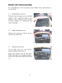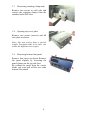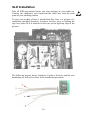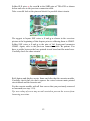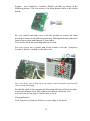
1
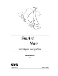
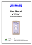
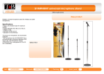
SLE SYMPHONY LOUDNESS ENABLER Installation & Users Manual for Rover 75 with Symphony Audio System (Alpine OEM) with or without Lo-Line Navigation Part No 02088 (intentionally left blank) Important Notice Please read this manual carefully before you start installing your Symphony Loudness Enabler into your head unit. You will be handling electrostatic sensitive devices, so be sure to follow all safety and ESD1-precautions before opening your radio set. Any warranty to your radio set will be lost after opening the case. Be aware that all changes that you make to your radio you do at your own risk! We do not take any responsibilities for possible defects or consequential damages related to this product. Contents Checklist...................................................................................................2 Supported Audio Systems.........................................................................2 Functional Descripton...............................................................................3 Operating Instructions...............................................................................4 Installation Instructions.............................................................................5 Radio Unit Disassembly......................................................................6 SLE Installation.................................................................................10 Test....................................................................................................14 Troubleshooting................................................................................15 Technical Data........................................................................................16 1 ESD: Electrostatic Discharge 1 Checklist This Symphony Loudness Enabler kit comprises following parts: • SLE module with pre-installed link line in sealed ESD bag, • Installation and users manual, • 2 distance bolts 10mm, 4 Screws M3, 2 washers, 2 lock washers, • 1 plastic cable tie. Before starting your work make sure, the following items are within reach: • Radio Security Code for activating your Radio after proper refit into the car, • Soldering Station with fine-pitch soldering iron, suitable for SMD soldering, zero-potential connector and conductive wrist band, • Set of normal and fine pitch screwdrivers. Supported Audio Systems The Symphony Loudness Enabler (SLE) kit may be installed into every Rover-75 Symphony Audio System with or without installed Lo-Line Navigation System or cellular handsfree set and also with the premium Harman-Kardon audio system. Your Symphony head unit is an Alpine OEM radio version. Until now there are no known limitations to special hardware or software versions of this type of radio set. SLE will fit into all versions. If you discover any problems or malfunctions please report them to the address printed on the back page of this manual. But please read the chapter Test & Troubleshooting before contacting us and be sure to report model number, hardware- and software version and the serial number of your radio set. 2 Functional Descripton Coming from factory you may have discovered that the Symphony/Alpine Audio System in your Rover-75 sounds quite poor, especially at low and mid range volumes. Changing the bass settings using the audio selector button won't really boost the lower frequencies to the desired values. Modern radio sets normally offer a function called Loudness. If enabled it activates a volume dependent filter unit which primarily boosts the low frequency range in order to increase dynamics. The higher the volume the lower the loudness fiter influences the normal audio frequency response. Unfortunately your Symphony Audio System offers no function key to activate loudness although the internal circuitry would allow this functionality to be enabled with a few additional components and a little software update. The Symphony Loudness Enabler simply attaches to the internal control data bus of your audio system and activates the loudness function of the sound and fader control unit. Some other components of Symphony Loudness Enabler are used to setup the loudness filter characteristics. There is no need for an expensive update of the main control software for your radio (if it would be possible at all) and you don't have to think about buying equalizers, boosters and a costly intstallation. Enabling and disabling your Symphony Loudness Enabler is done by pressing the PHONE button for at least two seconds. If disabled, the Symphony Loudness Enabler is completely passive and won't do anything on the internal data bus until it is re-activated. The normal functionality of the PHONE-button won't be affected by Symphony Loudness Enabler. 3 Operating Instructions Turning loudness ON and OFF is very simple and is done with the PHONE button which has no function in all known Symphony Audio Systems. Turning loudness ON and OFF Pressing and holding the PHONE button for at least two seconds toogles the operational state of Symphony Loudness Enabler between ON and OFF. The setting is permanently stored until you change it. So once activated it keeps being activated even if you turn off ignition. IMPORTANT: Neither you will hear a confirmation beep nor an immediate change of sound after you've pressed the PHONE button for at least two seconds. The next time you change the volume or audio settings (bass/treble/balance/fader) you will hear the effect for the first time. There is also no indicator which displays the current setting of Symphony Loudness Enabler to you. You may detect the state just by listening to the sound. It will be obvious. Again: The new setting will be stored permanently and won't be lost after turning off your radio set or ignition. Note: As the normal functionality of your radio is not changed, there will be the message „NO PHONE“ shown at the display when you press the PHONE button, regardless how long you press it. You may ignore this message. 4 Installation Instructions The complete Symphony Loudness Enabler installation procedure is split into three parts. • Head unit disassembly Instructions how to remove covers, finisher, screws and connectors in order to remove the complete radio head unit from your car. Instructions how to open and disassemble parts of your radio unit in order do start connecting SLE to your radio. • Symphony Loudness Enabler installation Instructions how and where to solder and connect the Symphony Loudness Enabler module to your radio electronics, as well as where and how to fix the module within the case. • Reassembly, Test & Troubleshooting Instructions how to reassemble your radio unit, perform tests, tips for troubleshooting, as well as instructions how to obtain serial number and hardware/firmware version codes prior to sending an error report if neccessary. Note: As stated above, any warranty to your radio set will be lost after opening the case. All changes that you make to your device you do at your own risk! 5 Radio Unit Disassembly For reinstallation of the head unit please follow these instructions in reverse order. 1.1 Head finisher removal Release clips securing cover to wooden finisher with a small screwdriver and remove cover. Remove two screws securing finisher to dashboard and remove finisher. 1.2 Radio mounting screws Remove two screws to release the top part of your radio unit. 1.3 Special tool 86.005 If you don't have the tool 86.005, please continue with step 1.4. Insert tool 86.005 into the flat slots. This will release the retaining clamps. Pull out the unit and continue with step 1.6 6 1.4 A/C finisher removal Without using the special tool 86.005 it is a better choice to get to the retaining clamps by removing some finishers than damaging the radio cover. Remove wooden finisher (below climate control panel) by slightly lifting it with a screwdriver from the left or right side. This makes it easier to remove the climate control panel. No screws to remove here. Remove the black climate control panel by releasing the clips around it - be careful 1.5 Releasing unit without using tool 86.005 If you lift the radio unit a few milimeters you will be able to see the retaining clamps to be pushed to the center with a flat screwdriver in order to release the radio unit. Be patient. This may take few seconds. Using a torch may be helpful. 1.6 Disconnecting radio unit from harness Disconnect three connectors at the left side by pressing the side clamps. Disconnect antenna connector and the IF diversity control line (black). Your radio unit should be free now. 7 1.7 Removing retaining clamp units Remove two screws at each side and remove the retaining clamps from the standard radio DIN case. 1.8 Opening top cover plate Remove two screws (arrows) and lift case plate as shown. Note: this two screws have a special length. Put them aside to be sure, not to mix the different screw types. 1.9 Removing button front panel Remove four screws as shown. Remove the panel slightly by loosening the panel-clamps on the top side first. By pulling the panel from the carrier frame you even pull off the two radio buttons. Be patient. 8 1.10 Removing cassette unit Remove three screws as shown and only losen one screw marked with an X. You don't have to remove it completely. Slightly lift the cassette unit from the mainboard connector at the back and remove the cassette unit. 1.11 Removing button and display carrier frame Remove two screws at the bottom and one screw at each side of the carrier frame. Now you can pull it from the case and disconnect it from two connectors. (picture shows top view) Now you are ready to begin connecting Symphony Loudness Enabler to your radio electronics. Continue with SLE Installation. 9 SLE Installation Take all ESD-precautions before you start working on your radio set. Connect the conductive wrist band and the radio case with the earth point of your soldering station. To give you an idea of how it should look like, here is a picture of a completely installed Symphony Loudness Enabler prior to refitting the top cover plate (SLE is mounted to the case on the right top edge of the picture): The following picture shows Symphony Loudness Enabler and the wire numbering we will refer to later in the installation procedure. 10 The connection table shows all links that have to be made. Experienced users may refer only to this information and skip the step-by-step installation procedure. wire name a (red) connect to TEA6320 - pin 1 b TEA6320 - pin 32 c TEA6320 - pin 9 d TEA6320 - pin 24 e (black or red) CB402 - pin 2 f CB402 - pin 12 g CB402 - pin 1 There are two locations you have to work at: It is the integrated circuit TEA6320 (A) and the left front-panel connector CB402 (B) as shown in the following picture (cassette drive dismounted). 11 Solder SLE wires a, b, c and d to the SMD-pins of TEA6320 as shown below and refer to the previous connection table. Take a careful look at the pins and check for possible short circuits. We suggest to layout SLE wires e, f and g as shown in the overview picture at the beginning of this chapter prior to soldering them to CB402. Solder SLE wires e, f and g to the pins of left front-panel connector CB402. Again, refer to the previous connection table. Be patient. You have to solder between the base printed circuit board and the metal case. Carefully check for short circuits. Refit button and display carrier frame and after that the cassette module. Carefully check that you don't squeeze the wires between main printed circuit board and the cassette unit. Fix the cassette module with all four screws that you previously removed or loosened (see step 1.10). Tip: use a drop of screw stop or nail varnish to prevent the screws from loosening over time. 12 Prepare your Symphony Loudness Enabler module as shown in the following picture. Use two screws to fix both distance bolts to the circuit board: Be very careful and make sure to fix the module at exactly the same position as shown in the following pictures. Misalignment may otherwise cause short circuits and damage to your radio! Two arrows show the mounting holes to be used. For every screw use a washer and a lock washer to fix the Symphony Loudness Enabler module to the radio case. Tip: even here, use a drop of screw stop or nail varnish to prevent all screws from loosening. Fix the flat cable to the cassette-deck housing with one cable tie in order to prevent damage to the SLE connections due to vibrations. The overview picture on page 10 shows how to fix it. Congratulations! Your Symphony Loudness Enabler is now ready to be tested. 13 Test Right after Symphony Loudness Enabler installation please go through the Radio Unit Disassembly chapter in a reverse order and stop at step 1.9 meaning: leave the top cover open to have a look at the red „act“ LED mounted on the Symphony Loudness Enabler module. Reconnect the radio set to all connectors of your car but don't install the device completely. You should be able to look inside the radio and onto the Symphony Loudness Enabler module. Turn on the radio and, if needed, enter the security code to activate your head unit. Search a suitable FM station or choose a cassette or CD. Best would be music. Press the sound and fader control button (right) until the display shows „FLAT“ before you increase volume. As Symphony Loudness Enabler is normally shipped with functional state ON you may have already noticed an audible sound improvement. If not, follow the operating instructions to enable Symphony Loudness Enabler. Turn the volume button and check if the red „act“ LED on the Symphony Loudness Enabler module flashes. Every time you change some audio settings you should discover a short flashing indicating that Symphony Loudness Enabler is active and influences communication on the control bus. If SLE is deactivated, you won't see any flashing. Now check, if the PHONE button is working right by following the operating instructions to toogle the operational state of Symphony Loudness Enabler between ON and OFF. If your head unit has passed the test please switch off radio and ignition and disconnect your radio from the radio harness and continue with chapter „Radio Unit Disassembly“, step 1.9 in reverse order. You may now use your radio and change bass, treble and fader settings as desired. 14 Troubleshooting If you experience any problems after installation of Symphony Loudness Enabler please check the following list: • check that every wire is connected according to the connection diagram, • check all pads for short circuits, especially at the SMD pins - a magnifying glass may be very helpful. If you still discover no activity please send an error report to us including an error description, the serial number (SN) and software version (SV) of your radio set. Service Mode To get the serial number and software version of your radio please follow this procedure: Turn off your radio. Turn on your radio and (if displayed) wait until the ROVER hello message has disappeared. Press the MAN button for at least eight seconds until SERVICEMODE is displayed. Write down the serial number (SN ...). Press the forward search button (>>) once and write down the software version code (SV xx-xx xx). Turn off the radio to leave service mode. It may also be helpful to write down all text on the label fixed at the bottom side of your radio. 15 Technical Data • operating voltage: 3 .. 6 V DC (head unit supplied) • supply current: typ. 1 mA (max. 6 mA) • operating temperature: - 40 .. 85 °C (industrial) • dimensions 34 x 25 x 5 mm • weight 5 g 16 (intentionally left blank) 17 HST-Systemtechnik Dipl.-Ing. H. Hutschenreiter Oberherrlinger Strasse 56 89134 Blaustein Germany phone +49 7304 919048 fax +49 7304 919047 [email protected] 0208804 02088-IM-h revised 12.2010