1
Division of BW Technologies
VA901T
Gas Detector
Applications 2776-2779
USER MANUAL
Protecting your health and your environment
Table of Contents
WARRANTY AND LIMITS OF LIABILITY ................................... 1
UNPACKING ............................................................................ 2
DESCRIPTION .......................................................................... 2
INSTALLATION GUIDELINES .................................................... 2
SPECIFICATIONS ...................................................................... 3
DETERMINING THE NUMBER OF TRANSMITTERS ..................... 4
SURFACE MOUNT INSTALLATION ............................................ 4
RANGE AND ALARM LEVELS ................................................... 5
WIRING DETAILS ..................................................................... 6
electrical wiring ..................................................................... 6
WIRING REQUIREMENTS ......................................................... 7
TYPICAL NETWORK DIAGRAM ..................................... 7
EOL NETWORK DIAGRAM .............................................. 8
KEY FUNCTION ....................................................................... 9
Zero key ................................................................................. 9
Span key ................................................................................ 9
DEVICE COMMUNICATION .................................................... 10
Dip Switch Settings ............................................................. 10
STRATEGIES .......................................................................... 11
OTHER FUNCTIONS ............................................................... 12
POINT DEFINITIONS ............................................................... 18
PERIODIC INSPECTION AND CALIBRATION ............................ 21
MAINTENANCE ...................................................................... 21
VA901T 509474
Dec 2005
1
WARRANTY AND LIMITS OF LIABILITY
WARRANTY AND LIMITS OF LIABILITY
Vulcain warrants to the original purchaser that its product, and the component parts
thereof, will be free from defects in workmanship and materials for a period of one year
from the date of purchase. Vulcain will, without any charge and at its option, repair or
replace defective products or components upon their delivery to its Repair and Service
Department. This warranty does not apply in the event of misuse or abuse of the product,
or as a result of unauthorized alterations or repairs. Vulcain shall not be liable for any
consequential damages, including, without limitation, damages resulting from loss of
use.
Every precaution for accuracy has been taken in the preparation of this manual.
However, Vulcain neither assumes responsibility for any omissions or errors that may
appear, nor liability for any damages that may result from the use of the products in
accordance with the information contained in this manual.
To obtain warranty service, return the product, along with a complete description of the
defect, transportation prepaid. Vulcain assumes no risk for damage in transit. Following
warranty repair, the product will be returned to the buyer, transportation prepaid.
Technical Support Line: 1-800-563-2967
Before returning a product for warranty service,
please contact Vulcain’s Technical Support
Department.
Warranty Registration
To validate the warranty, this registration form must be completed in full and sent to
Vulcain within 90 days of the date of purchase. Fax it to Vulcain at 1 888 967-9938.
Customer’s name:
Address:
City
State/Province:
Location of installation:
Serial number:
BEFORE RETURNING ANY INSTRUMENTS, PLEASE CONTACT US TO
OBTAIN A RETURN OF MATERIAL AUTHORIZATION NUMBER.
VA901T 509474
Dec 2005
1
UNPACKING
UNPACKING
After opening the package and removing the equipment and
components, make sure that you have all the items described on the
order form or packing slip.
DESCRIPTION
The VA901T Detector is a gas detection device built, sold, and serviced
by Vulcain. Vulcain offers a built-in Floor Level Network (FLN)
communication driver and point database allowing the detector to
coexist on an APOGEE network with other FLN devices. This
document describes how the VA901T can be accessed through a field
panel and how it can be used as a part of a larger control scheme.
The VA901T can be shipped with one of four sensor types: CO, O2,
NO2, and combustibles.
INSTALLATION GUIDELINES
A Vulcain representative is responsible for proper configuration of the
detector for its primary application, while a Siemens Building
Technologies representative is responsible for field panel
programming, to make use of the detector's functionality in the building
automation system. As such, there must be coordination between
Vulcain and Siemens Building Technologies representatives to ensure
that programming of the VA901T is consistent with requirements for
field panel programming.
•
•
•
•
•
2
Make sure to locate the detector and sensing assembly(ies) in an
area easily accessible to a technician.
Avoid any location where the detector could be subject to
vibrations.
Avoid any location close to noisy equipment.
Avoid any location where temperature changes occur rapidly.
Verify all the requirements and existing regulations which may
affect the choice of location.
Dec 2005
VA901T 509474
SPECIFICATIONS
SPECIFICATIONS
Power Requirements:
17 - 26 Vac, 100 mA @ 24 Vdc
Operating Temperature
Range:
-40°F to 122°F (-40°C to 50°C)
Operating Humidity Range: 0% to 95% RH Non-condensed
Sensing Technologies:
Q1: electrochemical (toxic)
catalytic combustion (combustible)
diffusion fuel cell (oxygen)
Visual Indicators:
Green LED: Full = Normal operation
Slow blink = Zero
calibration mode
Fast blink = Span
calibration mode
Communication
(length of lines):
Up to 2000 feet (600 m) per channel
T-tap: 65 feet (20 m) maximum per t-tap
130 feet (40 m) total
Minimum size Conductors: Twisted & shielded pair 24AWG wires
Storage Temperature:
32°F to 68°F (0°C to 20°C)
Communication:
RS-485 two wires
Communication Protocol: Autodetect FLN
Sensor types:
CO - Carbon monoxide (application 2779)
O2 - Oxygen (application 2778)
NO2 - Nitrogen dioxide (application 2776)
Combustibles (application 2777)
Transmission Speed:
4800 bps, half duplex, 8 bits of data, 1 stop
bit
Dimensions:
6.1 x 5 x 2.3 in. / 15.25 x 12.5 x 5.75 cm
Weight:
1.65 lb. (750 g)
VA901T 509474
Dec 2005
3
DETERMINING THE NUMBER OF TRANSMITTERS
DETERMINING THE NUMBER OF TRANSMITTERS
The number of transmitters required is determined by a unit’s operational
surveillance radius. Using the table below, the number of units required can
be easily evaluated.
Gas Detected
Surveillance Radius
Area Covered
CO
Carbon monoxide
50 feet (7 m)
7,854 sq. ft. (707 sq. m)
O2
Oxygen
23 feet (7 m)
1,257 sq. ft (154 sq. m)
NO2
Nitrogen dioxide
50 feet (15 m)
7,854 sq.ft (707 sq. m)
23 feet (7 m)
1,257 sq. ft (154 sq. m)
Comb Combustible
SURFACE MOUNT INSTALLATION
Installation simply requires the physical mounting of the enclosure and
connection of the power and output lines.
Recommended Height
Gas Detected
Relative Density
(air = 1)
Height
CO
Carbon monoxide
0.968
3 - 5 feet (1 - 1.5m) from floor
O2
Oxygen
1.43
3-5 ft (1-1.5m) from floor
NO2
Nitrogen dioxide
1.58 (cold)
1-3 ft (30cm - 1m) from ceilinga
Comb Most combustibles are heavier than air, with the exception of methane,
hydrogen, ethylene and acetylene. For gases that are heavier than air,
sensors should be installed approximately 30 cm (1 ft) from the floor. For
combustibles that are lighter that air, sensors should be installed 30 cm (1 ft)
from the ceiling, close to the potential leak source.
a. May differ in certain applications: Hot NO2 from exhaust systems is lighter than
ambient air.
4
Dec 2005
VA901T 509474
RANGE AND ALARM LEVELS
Combustible Interfering Gases Sensor
Gas
Catalytic Gas
factor (1)
Catalytic
factor (1)
Acetone
2.208
Hydrogen
1.233
Acetylene
1.665
Isopropyl alcohol
2.582
Butane
--
Cyclohexane
2.492
Methane
1.000
Methylethyl ketone
2.631
Ethylacetate
2.563
Octane
--
Ethylene
1.537
Pentane
--
Heptane
--
Propane
1.883
Hexane
--
Toluene
2.470
Enleaded petrol
--
RANGE AND ALARM LEVELS
Range and Alarm Levels (Factory setting)
Detected Gas
Range
ALR LO
MIN
ALR LO
MAX
ALR HI
MIN
ALR HI
MAX
25 ppm
180 ppm
200 ppm
CO
Carbon monoxide
0-250ppm
20 ppm
O2
Oxygen
0-25.5 %
vol
20.0% vol 19.5% vol
NO2
Nitrogen dioxide
0-10.2ppm 0.6ppm
0.7ppm
1.0ppm
2.0ppm
COMB
Combustibles
0-102%
LEL
25.0%
LEL
45.0%
LEL
50.0%
LEL
VA901T 509474
20.0%
LEL
Dec 2005
21.5% vol 22.0% vol
5
WIRING DETAILS
WIRING DETAILS
D0
D6
LOCK
ELECTRICAL WIRING
LED
SW3
DIP SWITCH
EOL resistor
U6
Zero Key
COMMUNICATION
Span Key
POWER
GND OUT
+24 Vdc
OUT
GND
+24 VDc
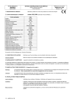
This drawing provides an overview of how the VA901T circuit
board looks when the unit is open. Consult the detailed wiring diagram on the next page for precise diagrams for wiring power and
communications.
6
Dec 2005
VA901T 509474
WIRING REQUIREMENTS
WIRING REQUIREMENTS
TYPICAL NETWORK DIAGRAM
Communication in
J7S
shield
EOL resistor
+
-
GND OUT
+24Vdc OUT
Communication out
Power out
GND
+24Vdc
J1
+
+
V+
V-
V+
V-
Power in
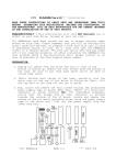
The diagram above illustrates the wiring technique for the VA901T in a
network setting.
J1 Power:
Illustrates both incoming and outgoing power
connections.
J7 Communication: Illustrates both incoming and outgoing
communication connections.
When wiring one of many units in a network, the wiring runs out from
one unit and in to the next unit until the End of Line (EOL) unit is
reached.
VA901T 509474
Dec 2005
7
WIRING REQUIREMENTS
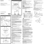
EOL NETWORK DIAGRAM
The End of Line, or EOL, wiring of a unit on a network means that
there is no other unit connected to the network beyond this point. The
unit is, thus, End of Line and there are no further connections to make.
Communication in
VA901T#
J7
shield
EOL resistor
S
+
-
GND OUT
EOL
+24Vdc OUT
GND
+24Vdc
J1
+
V+
V-
Power in
The unit that is destined to be End-Of-Line is preset at the factory and
labeled EOL. Simply remove the jumper from the resistor pins to
remove the EOL termination from the unit or place the jumper over the
first two resistor pins to make the unit the EOL, as shown in the
following drawing.
End of line OFF
EOL resistor
End of line jumper ON
EOL resistor
8
Dec 2005
VA901T 509474
KEY FUNCTION
KEY FUNCTION
The circuit board offer two buttons, or switches, each performing a
specific function:
Zero key
The zero key provides the unit with the zero reference. This function
must be performed without any calibration gas connected. To unlock the
function, put switch D7 (lock) in the OFF position (see wiring details).
This activates the calibration. By pressing the Zero key, the calibration
will be activated and the LED will blink slowly for 15 to 30 seconds.
The LED will stop blinking when the calibration is complete.
Span key
This function calibrates the sensor span. The calibration gas must be
connected to the unit. To unlock the function, put switch D7 (lock) in the
OFF position (see wiring details). By pressing the span key, the
calibration will be activated and the LED will blink quickly for 1 to 2
minutes. The LED will stop blinking when the calibration is complete.
VA901T 509474
Dec 2005
9
DEVICE COMMUNICATION
DEVICE COMMUNICATION
This device is a slave device must be integrated into a Floor Level
Network, called FLN, with a master (controller, software, etc.). Vulcain
devices respond to P1 commands.
Dip Switch Settings
8
7
D0
LOCK
D6
The detector address is selected (in binary format) with dip switches D6
to D0 (MSB to LSB) on SW3.
6
5
4
3
2
SW3
1
ON
The dip switch is labeled 1 through 8. Switch 8 (binary value D7 on the
circuit board) is the assigned “LOCK” switch, which locks the Zero
and Span keys to prevent accidental activation. Switches labeled 1
through 7 each represent a binary value on the circuit board (D0 to D6).
Each of these switches is associated to a value, known as a “weight”,
assigned to its ON position (the OFF position has no value), as shown
in the table below:
Switch Number
1
2
3
4
5
6
7
Binary PCB
number
D0
D1
D2
D3
D4
D5
D6
Value
1
2
4
8
16
32
64
These possible combinations of switch settings allow for up to 128
addresses, as in this example if:
Switch D3: ON = 4
Switch D4: ON = 8
Switch D6: ON = 64
10
Dec 2005
VA901T 509474
STRATEGIES
Add the values of all the switches that are on to obtain the device’s
address (4+8+64=76). If all the switches are in the ON position, the
maximum address value would be 127, however, the FLN protocol only
supports address values from 1 to 98. Address 99 is reserved for
backdoor access (remote calibration, etc.). All address values above 98
will be defaulted to the backdoor address value. Address 127 is reserved
for Vulcain programming use.
The detector’s address is updated only at startup, which means that you
will have to cut power to the device and power up again. A firmware (P1
command) or can also be used to validate a new address.
STRATEGIES
Monitoring
Monitoring
Alarm LDIs
VA901T 509474
Several detector parameters are available for monitoring
purposes. These include GAS CONC (Point 4), ALR LO
FLAG (Point 90) and ALR HI FLAG (Point 91). These
points can be unbundled for monitoring or used in
various global control strategies.
ALR LO FLAG (Point 90) and ALR HI FLAG (Point
91). These flags are ON when the gas concentration
exceeds alarm levels. For example, these flags can be
used to start ventilation or activate a buzzer.
Dec 2005
11
OTHER FUNCTIONS
OTHER FUNCTIONS
Set zero
CMD SET ZERO (Point 23) is the command used to
calibrate the zero of the sensor, which is the reference
for the detector when no GAS is present. When ordered,
this point will return to STOP by itself and it’s initial
value cannot be changed.
NOTE: This command will affect the detector's calibration.
Set span
CMD SET SPAN (Point 22) is the command used to
calibrate the sensor with a specific gas concentration.
The concentration applied to the detector is specified in
the GAS SPAN (Point 6) field. When ordered, this point
will return to STOP by itself and it’s initial value cannot
be changed.
NOTE: This command will affect the detector's calibration.
Analog Inputs SENSOR TYPE (point 3) shows the gas type detected
by the detector, according to the table below:
SENSOR TYPE Target Gas
2
CO
Carbon monoxide
3
O2
Oxygen
5
NO2
Nitrogen dioxide
20
COMB
Combustible gases
Other analog inputs include: GAS CONC (point 4) shows the current
gas concentration. SENSOR TEMP (point 11) gives the temperature
inside the detector. RUN TIME (point 12) is the number of days the
sensor has been on.
12
Dec 2005
VA901T 509474
OTHER FUNCTIONS
Digital Inputs ALR LO FLAG (Point 90) and ALR HI FLAG (Point
91) are the main physical DIs on the VA901T. They
correspond to a specific gas concentration limit. the low
level, ALR LO FLAG (point 90), is set when the gas
concentration reaches the ALR LO MAX level (point 8),
and cleared when the gas concentration returns under the
ALR LO MIN level (point 7). In the same way, the high
level alarm, ALR HI FLAG (point 91) is set when the
gas concentration reaches the ALR HI MAX level (point
10) and cleared when the gas concentration is lower than
ALR HI MIN (point 9).
Example for Oxygen sensor: Normally, there is 20.9% VOL of oxygen
in the air. It is good practice to detect when there is too much oxygen
(ALR HI FLAG) and when there is not enough (ALR LO FLAG). The
ALR HI FLAG works as described in the previous paragraph. However,
for the ALR LO FLAG, the MIN value must be higher that the MAX
value for proper use. This instruction tells the detector to use negative
trig for this flag (normally used when the alarm level is under the normal
concentration). In such a case, the current flag will be set when the
oxygen concentration is under the MAX level and is cleared when the
concentration rises above the MIN value.
Address
limitations
VA901T 509474
The default value for CTLR ADDRESS (Point 1) is 99 the maximum address value allowed in the FLN
specifications
Dec 2005
13
Point
Type
LAO
LAO
LAI
LAI
LAI
LAO
LAO
LAO
LAO
LAO
LAI
LAI
LAI
LAI
LAO
LDO
LDO
LDO
LDI
LDI
LDI
LDO
LAI
CTRL ADDRESS
APPLICATION
SENSOR TYPE
GAS CONC
FULL SCALE
GAS SPAN
ALR LO MIN
ALR LO MAX
ALR HI MIN
ALR HI MAX
SENSOR TEMP
RUN TIME
ADC FULL
ADC ZERO
OVRD TIME
CMD SET SPAN
CMD SET ZERO
DAY.NIGHT
ALR LO FLAG
ALR HI FLAG
SNS WARM UP
RESET FAULT
ERROR STATUS
Subpoint Name
Factory Default
(SI Units)
99
2776
0
0
0
0
0
0
0
0
0
0
4095
0
1
STOP
STOP
DAY
NORMAL
NORMAL
READY
NORMAL
0
ppm
PPM
PPM
PPM
PPM
PPM
PPM
DEG F (DEG C)
DAYS
ADC
ADC
-
Emgr Units
Slope
(SI Units)
1
1
1
0.1
0.1
0.1
0.1
0.1
0.1
0.1
0.18 (0.1)
1
1
1
1
1
Intercept
(SI Units)
0
0
0
0
0
0
0
0
0
0
-40
0
0
0
0
0
START
START
NIGHT
RUN
START
WARMUP
RESET
-
On Text
STOP
STOP
DAY
NORMAL
NORMAL
READY
NORMAL
-
Off Text
14
Dec 2005
VA901T 509474
NOTE: Points not listed are not used in this application. A single value in a column means that the value is the same in
English units and in SI units. Point numbers that appear in brackets {} may be unbundled at the field panel.
Point
Number
01
02
03
{04}
05
06
07
08
09
10
11
12
13
14
20
22
23
{29}
{90}
{91}
92
{94}
{99}
Point Data base for Nitrogen dioxide.
OTHER FUNCTIONS
Point
Type
LAO
LAO
LAI
LAI
LAI
LAO
LAO
LAO
LAO
LAO
LAI
LAI
LAI
LAI
LAO
LDO
LDO
LDO
LDI
LDI
LDI
LDO
LAI
CTRL ADDRESS
APPLICATION
SENSOR TYPE
GAS CONC
FULL SCALE
GAS SPAN
ALR LO MIN
ALR LO MAX
ALR HI MIN
ALR HI MAX
SENSOR TEMP
RUN TIME
ADC FULL
ADC ZERO
OVRD TIME
CMD SET SPAN
CMD SET ZERO
DAY.NIGHT
ALR LO FLAG
ALR HI FLAG
SNS WARM UP
RESET FAULT
ERROR STATUS
Subpoint Name
Factory Default
(SI Units)
99
2777
0
0
0
0
0
0
0
0
0
0
4095
0
1
STOP
STOP
DAY
NORMAL
NORMAL
READY
NORMAL
0
PCTLEL
PCTLEL
PCTLEL
PCTLEL
PCTLEL
PCTLEL
PCTLEL
DEG F (DEG C)
DAYS
ADC
ADC
-
Emgr Units
Slope
(SI Units)
1
1
1
0.1
0.1
0.1
0.1
0.1
0.1
0.1
0.18 (0.1)
1
1
1
1
1
Intercept
(SI Units)
0
0
0
0
0
0
0
0
0
0
-40
0
0
0
0
0
START
START
NIGHT
RUN
START
WARMUP
RESET
-
On Text
STOP
STOP
DAY
NORMAL
NORMAL
READY
NORMAL
-
Off Text
VA901T 509474
Dec 2005
15
Points not listed are not used in this application. A single value in a column means that the value is the same in English
units and in SI units. Point numbers that appear in brackets { } may be unbundled at the field panel.
Point
Number
01
02
03
{04}
05
06
07
08
09
10
11
12
13
14
20
22
23
{29}
{90}
{91}
92
{94}
{99}
Point Data base for Application Combustibles.
OTHER FUNCTIONS
Point
Type
LAO
LAO
LAI
LAI
LAI
LAO
LAO
LAO
LAO
LAO
LAI
LAI
LAI
LAI
LAO
LDO
LDO
LDO
LDI
LDI
LDI
LDO
LAI
CTRL ADDRESS
APPLICATION
SENSOR TYPE
GAS CONC
FULL SCALE
GAS SPAN
ALR LO MIN
ALR LO MAX
ALR HI MIN
ALR HI MAX
SENSOR TEMP
RUN TIME
ADC FULL
ADC ZERO
OVRD TIME
CMD SET SPAN
CMD SET ZERO
DAY.NIGHT
ALR LO FLAG
ALR HI FLAG
SNS WARM UP
RESET FAULT
ERROR STATUS
Subpoint Name
Factory Default
(SI Units)
99
2778
0
0
0
0
0
0
0
0
0
0
4095
0
1
STOP
STOP
DAY
NORMAL
NORMAL
READY
NORMAL
0
Slope
Intercept
(SI Units)
(SI Units)
1
0
1
0
1
0
PCTVOL
0.1
0
PCTVOL
0.1
0
PCTVOL
0.1
0
PCTVOL
0.1
0
PCTVOL
0.1
0
PCTVOL
0.1
0
PCTVOL
0.1
0
DEG F (DEG C) 0.18 (0.1)
-40
DAYS
1
0
ADC
1
0
ADC
1
0
1
0
1
0
Emgr Units
START
START
NIGHT
RUN
START
WARMUP
RESET
-
On Text
STOP
STOP
DAY
NORMAL
NORMAL
READY
NORMAL
-
Off Text
VA901T 509474
Dec 2005
16
Points not listed are not used in this application. A single value in a column means that the value is the same in English
units and in SI units. Point numbers that appear in brackets { } may be unbundled at the field panel.
Point
Number
01
02
03
{04}
05
06
07
08
09
10
11
12
13
14
20
22
23
{29}
{90}
{91}
92
{94}
{99}
Point Data base for Oxygen.
OTHER FUNCTIONS
Point
Type
LAO
LAO
LAI
LAI
LAI
LAO
LAO
LAO
LAO
LAO
LAI
LAI
LAI
LAI
LAO
LDO
LDO
LDO
LDI
LDI
LDI
LDO
LAI
CTRL ADDRESS
APPLICATION
SENSOR TYPE
GAS CONC
FULL SCALE
GAS SPAN
ALR LO MIN
ALR LO MAX
ALR HI MIN
ALR HI MAX
SENSOR TEMP
RUN TIME
ADC FULL
ADC ZERO
OVRD TIME
CMD SET SPAN
CMD SET ZERO
DAY.NIGHT
ALR LO FLAG
ALR HI FLAG
SNS WARM UP
RESET FAULT
ERROR STATUS
Subpoint Name
Factory Default
(SI Units)
99
2779
0
0
0
0
0
0
0
0
0
0
4095
0
1
STOP
STOP
DAY
NORMAL
NORMAL
READY
NORMAL
0
Slope
Intercept
(SI Units)
(SI Units)
1
0
1
0
1
0
PPM
1
0
PPM
1
0
PPM
1
0
PPM
1
0
PPM
1
0
PPM
1
0
PPM
1
0
DEG F (DEG C) 0.18 (0.1)
-40
DAYS
1
0
ADC
1
0
ADC
1
0
1
0
1
0
Emgr Units
START
START
NIGHT
RUN
START
WARMUP
RESET
-
On Text
STOP
STOP
DAY
NORMAL
NORMAL
READY
NORMAL
-
Off Text
17
Dec 2005
VA901T 509474
Points not listed are not used in this application. A single value in a column means that the value is the same in English
units and in SI units. Point numbers that appear in brackets {} may be unbundled at the field panel.
Point
Number
01
02
03
{04}
05
06
07
08
09
10
11
12
13
14
20
22
23
{29}
{90}
{91}
92
{94}
{99}
Point Data base for Carbon monoxide.
OTHER FUNCTIONS
POINT DEFINITIONS
POINT DEFINITIONS
Point 01
CTLR ADDRESS
This point contains the device address. The default
value is 99 (Backdoor address), however, the initial
value is set on the hardware (Dip Switch SW3). The
detector always answers to adress 99. This point cannot
be changed by software (P1 Command) and a reset of
the unit is needed to update the value of this register
(reset can be done with a P1 command).
Point 02
APPLICATION
This point shows the current application number for this
product.
Point 03
SENSOR TYPE
This point shows the gas type detected by the detector.
Point 04
GAS CONC
The gas concentration can be read with this point. It
shows the current gas concentration of its surveillance
area.
Point 05
FULL SCALE
This status point shows the maximum limit
(concentration) of the detection range.
Point 06
GAS SPAN
This point contains the concentration of the gas used for
the span calibration.
Point 7-10
ALARM PNT
These points specify alarm levels. Refer to Digital
Inputs on page 17 for more detail.
Point 11
SENSOR TEMP
Shows the temperature inside the detector.
18
Dec 2005
VA901T 509474
POINT DEFINITIONS
Point 12
CO RUN TIME
This point shows the running time (in days) of the
sensor. The point is reset to default value (0) when a
'Factory Reset' is ordered.
Point 20
OVRD TIME
Used to count the time the device is in 'override' mode.
Point 22
CMD SET SPAN
This point is used for the span calibration. When this
point is ordered (value is 'START'), the device will
calibrate its reading with the gas specified in the GAS
SPAN point and the concentration read by the detector.
When done, the point returns to STOP by itself.
NOTE: This command will affect the detector's calibration.
Point 23
CMD SET ZERO
This point is used for the zero calibration. When done,
the point returns to STOP by itself. Note: Setting this
point to STOP, from the START position, will cancel the
calibration.
NOTE: This command will affect the detector's calibration.
Point 29
DAY.NIGHT
This point tells the detector to run in day or night mode.
These modes are not supported by the detector.
Point 90 - 91 ALR LO FLAG and ALR HI FLAG
This points shows the status of the corresponding alarm
level.
Point 92
SNS WARMUP
This point shows if the sensor is in warmup mode and
returns to “ready” when the sensor has finished the
warmup. Avoid calibration during warmup.
NOTE: Not all sensors require a warmup period.
VA901T 509474
Dec 2005
19
POINT DEFINITIONS
Point 94
RESET FAULT
This point can be used as a LDO for detecting 'not
Commanded Reset'. Set the initial value to RESET and
set the current value to NORMAL. When a reset
appends, this point will toggle to RESET.
Point 99
ERROR STATUS
This point shows current errors on the detector. See the
table below for details
Fault:
ERROR STATUS (Point 99).
This point uses a bit field definition as described below.
When the sensor is NOT calibrated, bit B2 is set. B3 is
for sensor related error. Ex.: eprom life has expired.
Service Alarm bit (B5) will be set after 15 months
without calibration.
Error Status Point Descriptions
20
Bit
If Set
B0
Read as “0”
B1
Read as “0”
B2
Sensor not calibrated
B3
Sensor error
B4
CPU error
B5
Service alarm
B6
Read as “0”
B7
Read as “0”
Dec 2005
VA901T 509474
PERIODIC INSPECTION AND CALIBRATION
PERIODIC INSPECTION AND CALIBRATION
This unit requires calibration. The calibration frequency will be
determined by the operating conditions, which includes extreme
temperatures, exposure to contaminants or gas. If the exposure to the
gas is greater than the unit’s full scale, the unit must be recalibrated. A
calibration inspection must be included as part of a routine maintenance
to ensure proper operation of the gas detection unit.
WARNING: If the unit’s span or zero cannot be adjusted, the sensor may
be approaching its end-of-life and have been contaminated with high
concentration of gas, and it must be replaced.
MAINTENANCE
The VA901T will provide years of service with minimal care.
Encapsulated electronic plug-in modules are protected from moisture
and corrosive environments.
1 Visually inspect, test and calibrate with gas at regular intervals to
ensure optimum operating condition periods.
2 An accurate maintenance log of all maintenance, calibration and
occurences must be kept for the proper service of this product.
NOTE: Do not expose the sensor to high pressure water spray. Sensors
should not be exposed to solvents.
VA901T 509474
Dec 2005
21