1
Measuring Device for Recording Meteorological Data at the
PV Plant
SMA METEO STATION
Installation Manual
MeteoStation-eng-IA-IUS122210 | Version 1.0
US
CA
AU
SMA America, LLC
Legal Restrictions
Copyright © 2012 SMA America, LLC. All rights reserved.
No part of this document may be reproduced, stored in a retrieval system, or transmitted, in any form
or by any means, be it electronic, mechanical, photographic, magnetic or otherwise, without the prior
written permission of SMA America, LLC.
Neither SMA America, LLC nor SMA Solar Technology Canada Inc. makes representations, express
or implied, with respect to this documentation or any of the equipment and/or software it may
describe, including (with no limitation) any implied warranties of utility, merchantability, or fitness for
any particular purpose. All such warranties are expressly disclaimed. Neither SMA America, LLC nor
its distributors or dealers nor SMA Solar Technology Canada Inc. nor its distributors or dealers shall
be liable for any indirect, incidental, or consequential damages under any circumstances.
(The exclusion of implied warranties may not apply in all cases under some statutes, and thus the
above exclusion may not apply.)
Specifications are subject to change without notice. Every attempt has been made to make this
document complete, accurate and up-to-date. Readers are cautioned, however, that
SMA America, LLC and SMA Solar Technology Canada Inc. reserve the right to make changes
without notice and shall not be responsible for any damages, including indirect, incidental or
consequential damages, caused by reliance on the material presented, including, but not limited to,
omissions, typographical errors, arithmetical errors or listing errors in the content material.
All trademarks are recognized even if these are not marked separately. Missing designations do not
mean that a product or brand is not a registered trademark.
The Bluetooth® word mark and logos are registered trademarks owned by Bluetooth SIG, Inc. and
any use of such marks by SMA America, LLC and SMA Solar Technology Canada Inc. is under
license.
SMA America, LLC
3801 N. Havana Street
Denver, CO 80239 U.S.A.
SMA Solar Technology Canada Inc.
2425 Matheson Blvd. E
8th Floor
Mississauga, ON L4W 5K5
Canada
Installation Manual
MeteoStation-eng-IA-IUS122210
3
Important Safety Instructions
SMA America, LLC
IMPORTANT SAFETY INSTRUCTIONS
SAVE THESE INSTRUCTIONS
This manual contains important instructions for the following products:
• SMA Meteo Station
• Module temperature sensor
• Power supply unit
This manual must be followed during installation and maintenance.
The product is designed and tested according to international safety requirements, but as with all
electrical and electronic equipment, certain precautions must be observed when installing and/or
operating the product. To reduce the risk of personal injury and to ensure the safe installation and
operation of the product, you must carefully read and follow all instructions, cautions and warnings
in this document.
Warnings in this document
A warning describes a hazard to equipment or personnel. It calls attention to a procedure or practice,
which, if not correctly performed or adhered to, could result in damage to or destruction of part or all
of the SMA equipment and/or other equipment connected to the SMA equipment or personal injury.
Symbol
Description
DANGER indicates a hazardous situation which, if not avoided, will result in
death or serious injury.
WARNING indicates a hazardous situation which, if not avoided, could result
in death or serious injury.
CAUTION indicates a hazardous situation which, if not avoided, could result
in minor or moderate injury.
NOTICE is used to address practices not related to personal injury.
4
MeteoStation-eng-IA-IUS122210
Installation Manual
SMA America, LLC
Important Safety Instructions
General Warnings
General Warnings
All electrical installations must be done in accordance with the local safety codes and the
National Electrical Code® ANSI/NFPA 70 or the Canadian Electrical Code® CSA C22.1. This
document does not and is not intended to replace any local, state, provincial, federal or national
laws, regulation or codes applicable to the installation and use of the product, including without
limitation applicable electrical safety codes. All installations must conform with the laws, regulations,
codes and standards applicable in the jurisdiction of installation. SMA assumes no responsibility for
the compliance or non-compliance with such laws or codes in connection with the installation of the
product.
For all repair and maintenance, always return the unit to an authorized SMA Service Center.
Before installing or using the product, read all of the instructions, cautions, and warnings in this
document.
Wiring of the product must be made by qualified personnel only.
Installation Manual
MeteoStation-eng-IA-IUS122210
5
Table of Contents
SMA America, LLC
Table of Contents
1
Information on this Document. . . . . . . . . . . . . . . . . . . . . . . 9
2
2.1
2.2
2.3
Safety . . . . . . . . . . . . . . . . . . . . . . . . . . . . . . . . . . . . . . . . . 11
Intended Use. . . . . . . . . . . . . . . . . . . . . . . . . . . . . . . . . . . . . . . 11
Qualification of Skilled Persons . . . . . . . . . . . . . . . . . . . . . . . . 12
Safety Instructions . . . . . . . . . . . . . . . . . . . . . . . . . . . . . . . . . . . 13
3
Scope of Delivery . . . . . . . . . . . . . . . . . . . . . . . . . . . . . . . . 14
4
4.1
4.2
Product Description . . . . . . . . . . . . . . . . . . . . . . . . . . . . . . 15
Meteo Station . . . . . . . . . . . . . . . . . . . . . . . . . . . . . . . . . . . . . . 15
Power Supply Unit . . . . . . . . . . . . . . . . . . . . . . . . . . . . . . . . . . 17
5
5.1
Mounting. . . . . . . . . . . . . . . . . . . . . . . . . . . . . . . . . . . . . . . 18
Mounting the Connecting Terminal Plate and the
Power Supply Unit . . . . . . . . . . . . . . . . . . . . . . . . . . . . . . . . . . 18
Mounting the Meteo Station. . . . . . . . . . . . . . . . . . . . . . . . . . . 18
Mounting the Module Temperature Sensor . . . . . . . . . . . . . . . 20
5.2
5.3
6
6.1
6.2
6.3
Commissioning . . . . . . . . . . . . . . . . . . . . . . . . . . . . . . . . . . 22
Terminal Assignment of the Pre-harnessed Connection Cable . 22
Connecting the Meteo Station to the
RS485 Communication Bus . . . . . . . . . . . . . . . . . . . . . . . . . . . 22
Connecting the Power Supply Unit to the Power Supply . . . . . 23
7
7.1
7.2
Troubleshooting . . . . . . . . . . . . . . . . . . . . . . . . . . . . . . . . . 24
Errors in the SMA Meteo Station . . . . . . . . . . . . . . . . . . . . . . . 24
Errors in the Power Supply Unit . . . . . . . . . . . . . . . . . . . . . . . . 25
8
8.1
8.2
Decommissioning . . . . . . . . . . . . . . . . . . . . . . . . . . . . . . . . 26
Disassembling the Meteo Station . . . . . . . . . . . . . . . . . . . . . . . 26
Disassembling the Module Temperature Sensor. . . . . . . . . . . . 26
6
MeteoStation-eng-IA-IUS122210
Installation Manual
SMA America, LLC
8.3
Table of Contents
8.4
8.5
Disassembling the Connecting Terminal Plate and
Power Supply Unit . . . . . . . . . . . . . . . . . . . . . . . . . . . . . . . . . . 26
Packing the Meteo Station for Shipping . . . . . . . . . . . . . . . . . . 27
Disposing of the Meteo Station. . . . . . . . . . . . . . . . . . . . . . . . . 27
9
9.1
9.2
Parameters . . . . . . . . . . . . . . . . . . . . . . . . . . . . . . . . . . . . . 28
Display Values . . . . . . . . . . . . . . . . . . . . . . . . . . . . . . . . . . . . . 28
Adjustable Parameters . . . . . . . . . . . . . . . . . . . . . . . . . . . . . . . 29
10
10.1
Technical Data . . . . . . . . . . . . . . . . . . . . . . . . . . . . . . . . . . 30
Meteo Station . . . . . . . . . . . . . . . . . . . . . . . . . . . . . . . . . . . . . . 30
11
Contact . . . . . . . . . . . . . . . . . . . . . . . . . . . . . . . . . . . . . . . . 33
Installation Manual
MeteoStation-eng-IA-IUS122210
7
1 Information on this Document
1
SMA America, LLC
Information on this Document
Validity
This manual is valid for the SMA Meteo Station from firmware version 2.80.01.
Target Group
This document is intended for skilled persons. Only skilled persons are allowed to perform the tasks
set forth in this document (see Section 2.2 "Qualification of Skilled Persons", page 11).
Symbols
Symbol
Explanation
Indicates a hazardous situation which, if not avoided, will result in death or
serious injury
Indicates a hazardous situation which, if not avoided, can result in death or
serious injury
Indicates a hazardous situation which, if not avoided, can result in minor or
moderate injury
Indicates a situation which, if not avoided, could result in property damage
Information that is important for a specific topic or goal, but is not safety-relevant
☐
☑
✖
8
Indicates a requirement for meeting a specific goal
Desired result
A problem that could occur
MeteoStation-eng-IA-IUS122210
Installation Manual
SMA America, LLC
1 Information on this Document
Typographies
Typography
"light"
Use
• Display messages on the
inverter
Example
• The value can be read in
the "Energy" field.
• Elements in a software
user interface
• Connections
• Elements to be selected
bold
>
• Several elements that are
to be selected
• Button or key to be
selected or pressed
[Button/Key]
• Enter 10 in the "Minutes"
field.
• Select Settings > Date.
• Select [Next].
Nomenclature
Complete designation
Designation in this document
SMA America Production, LLC and
SMA Solar Technology Canada Inc.
SMA
SMA Meteo Station
Meteo Station
Abbreviations
Abbreviations
AF
Designation
Width Across Flats
MEMS
MSL
NTC
Micro-Electro-Mechanical System
Mean Sea Level
Negative Temperature Coefficient
Thermistors
Photovoltaics
PV
Installation Manual
Explanation
The distance between two parallel flat
surfaces ("flats") of a screw head.
‒
‒
Electric resistor with a negative
temperature coefficient
‒
MeteoStation-eng-IA-IUS122210
9
2 Safety
2
SMA America, LLC
Safety
2.1 Intended Use
SMA Meteo Station
The Meteo Station is a device for measuring power-related meteorological data at the PV plant
location and for transmitting this data to the Sunny WebBox via RS485 communication bus.
The Meteo Station fulfills the following tasks:
Measurement of global radiation, PV cell temperature, absolute air pressure, air temperature and
humidity, and transmission of this data to the Sunny WebBox.
Any other use can result in personal injury or property damage. The SMA Meteo Station's degree of
protection is NEMA 3 and is suitable for outdoor and indoor use within a temperature range of
− 40°F to +140°F ( − 40°C to +60°C).
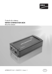
Figure 1:
Example: Diagram of a PV plant with Meteo Station and Sunny WebBox
Position
Description
A
PV module with module temperature sensor
10
MeteoStation-eng-IA-IUS122210
Installation Manual
SMA America, LLC
2 Safety
Position
Description
B
Meteo Station
C
Connecting terminal plate
D
Power supply unit
E
Grid connection
F
RS485 bus node (e.g., PV inverter)
G
Sunny WebBox
The Meteo Station is approved exclusively for use with the supplied module temperature sensor, the
supplied power supply unit and any other RS485-compatible SMA devices.
For safety reasons, it is forbidden to modify the product or install components that are not explicitly
recommended or distributed by SMA.
The enclosed documentation is an integral part of this product.
• Read and adhere to the documentation.
• Keep the documentation in a convenient place for future reference.
2.2 Qualification of Skilled Persons
The tasks described in this document must be performed by skilled persons only. Skilled persons must
have the following qualifications:
• Training in the installation and commissioning of electrical devices
• Knowledge of all applicable standards and guidelines
Installation Manual
MeteoStation-eng-IA-IUS122210
11
2 Safety
SMA America, LLC
2.3 Safety Instructions
Danger to life due to electric shock
Lethal voltages are present in the conductive parts inside the power supply unit.
• Never open the power supply unit.
The power supply unit is not splash-proof.
If moisture penetrates the power supply unit, you may suffer an electric shock upon contact.
• Only use the power supply unit in a dry, indoor environment.
Risk of injury due to stumbling
Incorrectly laid cables may cause injuries due to tripping hazard.
• Lay the cables in such way that no one can step on or trip over them.
Damage to the SMA Meteo Station by lightning strike
The Meteo Station is not equipped with lightning protection. A lightning strike could damage or
destroy the Meteo Station.
• The Meteo Station must be integrated in the existing lightning protection equipment.
Damage to the power supply unit due to moisture penetration
The power supply unit is not splash-proof.
• Only use the power supply unit in a dry, indoor environment.
12
MeteoStation-eng-IA-IUS122210
Installation Manual
SMA America, LLC
3
3 Scope of Delivery
Scope of Delivery
Check the delivery for completeness and any visible external damage. Contact your specialty retailer
if the delivery is incomplete or you find any damage.
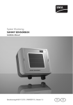
Figure 2:
Components included in the scope of delivery
Position
Quantity
Description
A
1
Meteo Station
B
1
Pre-harnessed connection cable
C
1
Module temperature sensor with cleaning cloth
D
1
CD with installation manual, quick reference guide for
commissioning, Technical Information "RS485 Cabling Plan"
E
1
Power supply unit Phoenix Contact
F
Installation Manual
3
Conductive adhesive foil
2
Shield connection terminal
MeteoStation-eng-IA-IUS122210
13
4 Product Description
4
SMA America, LLC
Product Description
4.1 Meteo Station
The Meteo Station is a device for measuring power-related meteorological data at the PV plant
location and for transmitting this data to the Sunny WebBox via the Power Injector. The Meteo Station
fulfills the following tasks:
• Measurement of global radiation
• Measurement of PV cell temperature
• Measurement of absolute air pressure
• Measurement of air temperature and humidity
• Transmission of this meteorological data to the Sunny WebBox
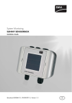
Figure 3:
Design of the Meteo Station
Position
Description
A
Pyranometer
B
Air pressure sensor in the device
C
Sensors for measuring air temperature and humidity
14
MeteoStation-eng-IA-IUS122210
Installation Manual
SMA America, LLC
4 Product Description
Position
Description
D
Fan
E
Device plug
F
Connection cable with female connector
G
Retaining bracket with springs and self-locking nuts
H
Notch to fix the connection cable
Pre-harnessed connection cable
Position
Description
A
Shield connection terminal
B
Connecting terminal plate with rail adapter and terminator
C
Device plug
Type Label
You can identify the Meteo Station by means of the type label. The type label is located on the
underside of the Meteo Station where the nuts and springs are also attached. You can read out the
following data from the type label:
• Serial number and hardware version
• Power consumption, operating voltage
• Permissible ambient temperatures during operation
• CE marking
The information on the type label is intended to help you use the SMA Meteo Station safely and will
be needed when you contact the SMA Service Line. The type label must be permanently attached to
the SMA Meteo Station.
Installation Manual
MeteoStation-eng-IA-IUS122210
15
4 Product Description
SMA America, LLC
4.2 Power Supply Unit
The power supply unit is a grid-powered voltage converter made by Phoenix Contact.
The power supply unit fulfills the following tasks:
• Voltage supply to the Meteo Station
It is not permitted to use the power supply unit for any other purpose. Any other use can result in
personal injury or property damage.
You will find precise information on the power supply unit in the attached installation instructions from
Phoenix Contact.
Only install the power supply unit as described in the installation instructions.
16
MeteoStation-eng-IA-IUS122210
Installation Manual
SMA America, LLC
5
5 Mounting
Mounting
5.1 Mounting the Connecting Terminal Plate and the
Power Supply Unit
Requirements:
☐ Adhere to the requirements in the attached installation instructions from Phoenix Contact.
☐ The mounting location must be indoors.
☐ A maximum cable route of 33 ft. (10 m) to the PV modules must be taken into account.
☐ A maximum RS485 communication bus length of 328 ft. (100 m) must be taken into account.
☐ The power supply unit must be protected from dust, moisture and aggressive substances.
1. Mount the power supply unit and connect it to the connecting terminal plate (see Installation
Instructions for Power Supply Unit from Phoenix Contact).
2. Mount the connecting terminal plate on the top-hat
rail.
5.2 Mounting the Meteo Station
Requirements:
☐ The ambient temperature must be between ‒40°F to +140°F ( − 40°C to +60°C).
☐ The diameter of the pole on which the Meteo Station is mounted must be between 2 3⁄8 in. and
3 in. (60 mm to 76 mm).
☐ The pole must be stabilized by an appropriate wall or floor fixture.
☐ The mounting location must be shadow-free and with an unimpeded panoramic view at the
height of the pyranometer.
☐ Remember that the maximum cable length to the connecting terminal plate is 33 ft. (10 m).
☐ The Meteo Station must be protected from aggressive or toxic substances.
Installation Manual
MeteoStation-eng-IA-IUS122210
17
5 Mounting
Figure 4:
SMA America, LLC
Parts of the Meteo Station which are relevant for mounting
Position
Description
A
Retaining bracket
B
Device plug
C
Spring
D
Nut and washer
E
Notch to fix the connection cable
F
Connection cable with female connector and screw ring
G
Pole
18
MeteoStation-eng-IA-IUS122210
Installation Manual
SMA America, LLC
5 Mounting
Additional tools required (not included in the scope of delivery):
☐ Metric wrench AF13
1. Connection cable from the connecting terminal plate to the mounting location of the
Meteo Station.
2. Remove the yellow cap from the device plug.
3. Press the connection cable into the notch to hold it in place on the Meteo Station and move the
female connector towards the device plug.
4.
Connect the cable, taking the position markings into account.
There is a keyway on the cable socket and a key on the device plug.
• When plugging the female connector, make sure that the keyway on the cable
socket and the key on the device plug are properly aligned.
5. Fasten the screw ring of the female connector. This holds the connection cable in place.
6. Unfasten both nuts on the retaining bracket of the Meteo Station.
7. Push the Meteo Station over the top end of the pole.
8.
You may damage the Meteo Station by fastening the nuts on the retaining bracket
too tight.
• Tighten both nuts until the springs on the retaining bracket begin to compress.
• Then fasten each nut with three turns.
5.3 Mounting the Module Temperature Sensor
Requirements:
☐ The module temperature sensor must be installed on a PV module that is not shaded at any time.
☐ A maximum cable route of 33 ft. (10 m) to the connecting terminal plate must be taken into
account.
Risk of burn injuries if you touch the PV modules
In strong, direct solar irradiation, PV modules can heat up to temperatures as high as
+176 °F (+80 °C).
• Mount the module temperature sensor at a time at which no direct sunlight is shining on the
PV modules.
Installation Manual
MeteoStation-eng-IA-IUS122210
19
5 Mounting
1.
SMA America, LLC
Cleaning the adhesive surface
The surface must be free of dirt and moisture, otherwise the module temperature sensor
is likely to fall off after sticking.
• Use the cleaning cloth to wipe the surface of the PV module at the spot where the
sensor is to be affixed. The spot must be located on the underside of the PV module.
2. Remove the masking paper from the pre-mounted double-sided adhesive tape on the module
temperature sensor.
3.
Damage to the PV module if you press the sensor on too hard
It is possible to damage the PV module by pressing the module temperature sensor on too hard.
• Observe the notes on mechanical strength in the PV module manual.
• Stick the module temperature sensor to the clean adhesive surface on the PV module,
pressing it on as firmly as the mechanical strength allows.
4. Lay the module temperature sensor cable to the
mounting location of the connecting terminal plate.
5. Connect one insulated conductor of the module
temperature sensor to Pin 5 and the other to Pin 6
of the connecting terminal plate. This can be done
in any order.
20
MeteoStation-eng-IA-IUS122210
Installation Manual
SMA America, LLC
6
6 Commissioning
Commissioning
6.1 Terminal Assignment of the Pre-harnessed Connection Cable
Pin no.
Color
Signal designation
1
white
Ground supply voltage (GND)
2
brown
Positive supply voltage (+12 V)
3
green
RS485 (D + )
4
yellow
RS485 (D − )
5
gray
Module temperature sensor
6
pink
Module temperature sensor
Insulated conductors 1 to 4 are already connected to the connecting terminal plate upon delivery.
The terminating resistor is connected between insulated conductors 3 and 4. Pins 5 and 6 must be
connected to the two insulated conductors of the module temperature sensor, in any order.
6.2 Connecting the Meteo Station to the RS485 Communication Bus
Requirement:
☐ The RS485 cable must be connected to the RS485 bus node (see manual of the RS485 bus node).
☐ Note the pre-harnessed termination of the Meteo Station by means of the terminator
(for details of the layout of the RS485-communication bus, see the technical description
"RS485 Cabling Plan").
1. Strip 8 in. (200 mm) of the cable sheath off the RS485 cable.
2. Shorten the cable shield to 1⁄2 in. (15 mm).
3. Trim the unneeded insulated conductors back as far as the cable sheath (for terminal assignment
and wiring, see the technical description "RS485 Cabling Plan").
4. Pull back the cable shield and cover with conductive
adhesive foil.
5. Connect the RS485 cable to the shield connection terminal of the connection cable, making
sure that the conductive adhesive foil has electrical contact to the shield connection terminal.
Installation Manual
MeteoStation-eng-IA-IUS122210
21
6 Commissioning
SMA America, LLC
6. Strip the insulation of both conductors of the RS485 cable by 1⁄4 in. (6 mm) and connect these
to Pin 3 and Pin 4 of the connecting terminal plate. Observe the correct polarity: "Data +" to
Pin 3 and "Data − " to Pin 4 (see 6.1 "Terminal Assignment of the Pre-harnessed Connection
Cable", page 21 and the technical description "RS485 Cabling Plan")
6.3 Connecting the Power Supply Unit to the Power Supply
Requirements:
☐ The module temperature sensor must be connected (see Section 5.3 "Mounting the Module
Temperature Sensor", page 19).
☐ The power supply unit must be connected to the connecting terminal plate
(see Section 5.3 "Mounting the Module Temperature Sensor", page 19).
☐ The SMA Meteo Station must be connected to the connecting terminal plate
(see Section 6.2 "Connecting the Meteo Station to the RS485 Communication Bus", page 21).
1. Install the power supply unit as described in the Installation Instructions for Power Supply Unit
from Phoenix Contact.
22
MeteoStation-eng-IA-IUS122210
Installation Manual
SMA America, LLC
7
7 Troubleshooting
Troubleshooting
7.1 Errors in the SMA Meteo Station
Problem
Cause and corrective measures
The Meteo Station is not
detected.
The RS485 communication bus is not terminated.
Corrective measures:
• Terminate the RS485 communication bus at the connecting
terminal plate (for information on termination, see the
technical description "RS485 Cabling Plan").
The Meteo Station cannot be
The RS485 communication bus is not terminated.
queried or does not respond to Corrective measures:
queries.
• Terminate the RS485 communication bus at the connecting
terminal plate (for information on termination, see the
technical description "RS485 Cabling Plan").
Supply voltage is interrupted.
Corrective measures:
• Ensure that the Meteo Station is supplied with voltage.
Cable shields are not properly positioned.
Corrective measures:
• Ensure that the cable shields are properly positioned and
connected to the shield connection terminal.
The Meteo Station reports error The sensor for measuring ambient temperature is faulty.
value 1 "ErrSensAmbTemp" or Corrective measures:
error value 6
• Contact the SMA Service Line
"WrnSensAmbTemp".
(see Section 11 "Contact", page 32).
The Meteo Station reports error
value 2 "ErrSensModTemp" or
error value 7
"WrnSensModTemp", or
unrealistic values are displayed
for the module temperature
sensor.
The module temperature sensor has no contact with the
PV module.
Corrective measures:
• Ensure that there is contact between the module
temperature sensor and the PV module.
The module temperature sensor is defective.
Corrective measures:
• Contact the SMA Service Line
(see Section 11 "Contact", page 32).
Installation Manual
MeteoStation-eng-IA-IUS122210
23
7 Troubleshooting
SMA America, LLC
Problem
Cause and corrective measures
The Meteo Station reports error The glass dome of the pyranometer is damaged or soiled.
value 3 "ErrSensSolIrr" or error Corrective measures:
value 8 "WrnSensSolIrr", or
• Clean the glass dome of the pyranometer.
unrealistic values are displayed
• Contact the SMA Service Line
for the pyranometer.
(see Section 11 "Contact", page 32).
The Meteo Station reports error The calibration data of the pyranometer is not valid.
value 4 "ErrCalibData" or error Corrective measures:
value 10 "WrnMtSensSolIrr".
• Register the Meteo Station at SMA for calibration
(see Section 11 "Contact", page 32).
The Meteo Station resports an
error value not listed here.
This can have various causes.
Corrective measures:
• Contact the SMA Service Line
(see Section 11 "Contact", page 32).
7.2 Errors in the Power Supply Unit
Problem
Cause and corrective measures
The "DC OK" LED on The power supply unit has no power.
the power supply unit is Corrective measures:
not lit.
• Check whether line voltage is available.
24
MeteoStation-eng-IA-IUS122210
Installation Manual
SMA America, LLC
8
8 Decommissioning
Decommissioning
8.1 Disassembling the Meteo Station
Additional tools required (not included in the scope of delivery):
☐ Metric wrench AF13
1. Remove the power supply unit from the power supply (see Installation Instructions for
Power Supply Unit from Phoenix Contact).
2. Unfasten both nuts on the retaining bracket of the Meteo Station.
3. Slide the SMA Meteo Station upwards and off the end of the pole.
4. Unscrew the screw ring and pull the connection cable out of the Meteo Station.
8.2 Disassembling the Module Temperature Sensor
1. Disconnect the two conductors of the module temperature sensor from the connecting terminal
plate.
2.
Damage to the PV module by removing the module temperature sensor
Do not remove attached sensors from PV modules, as otherwise the modules may be damaged.
The module temperature sensor cannot be re-used.
• Cut the sensor cable off flush with the module temperature sensor.
8.3 Disassembling the Connecting Terminal Plate and
Power Supply Unit
1. Lever the connecting terminal plate from the bottom
of the top-hat rail forward and out. To do this, apply
downward pressure.
2. After releasing the bottom of the connecting terminal
plate, pull it upwards off the top-hat rail.
3. Remove the power supply unit from the top-hat rail (see Installation Instructions for Power Supply
Unit from Phoenix Contact).
Installation Manual
MeteoStation-eng-IA-IUS122210
25
8 Decommissioning
SMA America, LLC
8.4 Packing the Meteo Station for Shipping
• Pack the device. For this purpose, use the original packaging or packaging suitable for the
weight and size of the device (see Section 10 "Technical Data", page 29).
8.5 Disposing of the Meteo Station
• Dispose of the device according to the disposal regulations for electronic waste that apply at
the installation site.
or
• Send the device to SMA at your own expense (for contact details, see Section
11 "Contact", page 32) Label the packaging "ZUR ENTSORGUNG" ("FOR DISPOSAL").
26
MeteoStation-eng-IA-IUS122210
Installation Manual
SMA America, LLC
9
9 Parameters
Parameters
9.1 Display Values
The parameters are divided into display values and adjustable parameters. Display values are read
only, adjustable parameters can also be changed.
Meteo Station
Name
Description
SN
Serial number of the SMA Meteo Station
FwVer
Firmware version of the SMA Meteo Station
HWVer
Hardware version of the SMA Meteo Station
OpTm
Operating time of the SMA Meteo Station since commissioning in hours
Mode
Display of operating states: 0 - normal operation, 1 - initialization,
2 - warning, 3 - error
Internal Global Radiation Sensor
Name
Description
IntSolIrr
Global radiation in W/m2
Module Temperature Sensor
Name
Description
TmpMdul C
Cell temperature in °C
TmpMdul K
Cell temperature in K
TmpMdul F
Cell temperature in °F
Ambient Temperature
Name
Description
TmpAmb C
Ambient temperature in °C
TmpAmb K
Ambient temperature in K
TmpAmb F
Ambient temperature in °F
Installation Manual
MeteoStation-eng-IA-IUS122210
27
9 Parameters
SMA America, LLC
Air Pressure and Humidity
Name
Description
envhmdt
Relative humidity in %
envpress
Air pressure in hPa
9.2 Adjustable Parameters
The parameters are divided into display values and adjustable parameters. Display values are read
only, adjustable parameters can also be changed.
Name
Description
Value/Range
Explanation
Default value
DevNam
Device Name
Text
Allocation of a random
designation with max.
32 characters
-
1,200 Baud
SMA-typical baud rate
1,200 baud
SMANetBd Bus speed
DevRs
28
Reset of the SMA A random
A reset is performed.
Meteo Station
numerical value
can be set to
trigger a reset of
the weather
station.
MeteoStation-eng-IA-IUS122210
-
Installation Manual
SMA America, LLC
10 Technical Data
10 Technical Data
10.1 Meteo Station
General Data
Certified countries
USA/Canada
Recommended installation location
Outdoors
Mechanical Data
Diameter x height
6 in. x 10 1⁄2 in. (150 mm x 268 mm)
Weight with bracket, without connection cable
3 lbs. (1.3 kg)
Mounting type
Pole fixtures: Ø 2 3⁄8 in. to 3 in.
(60 mm to 76 mm)
Voltage Supply
Voltage supply
Power supply unit
Supply voltage
24 V DC ± 20%
Typical current input
135 mA
Maximum current consumption
500 mA
Typical power consumption
<2W
Ambient Conditions
Degree of protection
NEMA 3
Ambient temperature
− 40°F to 140°F ( − 40°C to +60°C)
Relative humidity
5% to 95 %
Max. permissible height above MSL
9,840 ft. (3,000 m)
Communication
Communication
Installation Manual
RS485
MeteoStation-eng-IA-IUS122210
29
10 Technical Data
SMA America, LLC
Air Temperature Measurement
Measuring procedure
NTC
Measuring range
− 58°F to 140°F ( − 50°C to +60°C)
Resolution
0.18°F at − 4°F to +122°F, otherwise 0.36°F
(0.1°C at − 20°C to +50°C, otherwise 0.2°C)
Accuracy of sensor
± 0.36°F at − 4°F to 122°F, otherwise 0.9°F
(± 0.2°C at − 20°C to +50°C, otherwise 0.5°C)
Measuring interval
1 minute
Units
°C, °F
Measurement of Humidity
Measuring procedure
Capacitive
Measuring range
0 to 100% relative humidity
Resolution
0.1% relative humidity
Accuracy
±2% relative humidity
Measuring interval
1 minute
Units
% relative humidity
Measurement of Air Pressure
Measuring procedure
MEMS sensor, capacitive
Measuring range
4.35 Psi to 17.4 Psi (300 hPa to 1,200 hPa)
Resolution
0.001 Psi (0.1 hPa)
Accuracy
±0.02 Psi (±1.5 hPa)
Measuring interval
1 minute
Pyranometer Sensor Kipp & Zonen CMP 3
Measuring procedure
Thermopile pyranometer
Measuring range
0.0 W/m2 to 1,400.0 W/m2
Resolution
< 1 W/m2
Measuring interval
1 minute
Certification according to ISO9060
second class
30
MeteoStation-eng-IA-IUS122210
Installation Manual
SMA America, LLC
10 Technical Data
Module Temperature Sensor
Measuring procedure
NTC
Cable length
33 ft. (10 m)
Measuring range
− 4°F to 176°F ( − 20°C to +80°C)
Measurement accuracy
< ±1.8°F (< ±1.0°C)
Measuring interval
1 minute
Installation Manual
MeteoStation-eng-IA-IUS122210
31
11 Contact
SMA America, LLC
11 Contact
If you have technical problems concerning our products, contact the SMA Service Line. We need the
following data in order to provide you with the necessary assistance:
• Serial number and firmware version of the SMA Meteo Station
• Serial number and firmware version of the Sunny WebBox
SMA Solar Technology America, LLC
6020 West Oaks Blvd, Ste 300
Rocklin, CA 95765
Tel. +1 916 625 0870
Tel. +1 877-MY SMA TECH
Tel. +1 877 697 6283 (Toll free, available for USA, Canada and Puerto Rico)
Fax +1 916 625 0871
[email protected]
www.SMA-America.com
SMA Solar Technology Canada Inc.
2425 Matheson Blvd. E, 8th Floor
Mississauga, ON L4W 5K5
Canada
Tel. +1 877 506 1756 (Toll free, available for Canada)
[email protected]
www.SMA-Canada.ca
SMA Technology Australia Pty. Ltd.
Suite 106, 30-40 Harcourt Parade
Rosebery, NSW 2018
Tel. +61 2 9669 2889
Fax +61 2 9669 2887
[email protected]
www.SMA-Australia.com.au
32
MeteoStation-eng-IA-IUS122210
Installation Manual
SMA America, LLC
4."4PMBS5FDIOPMPHZ
XXX4."4PMBSDPN
4.""NFSJDB--$
XXX4.""NFSJDBDPN
Installation Manual
MeteoStation-eng-IA-IUS122210
35