1
System Monitoring
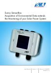
SUNNY SENSORBOX
Installation Guide
Sensorbox-IUS084413 | 98-0003913 | Version 1.3
US
SMA Solar Technology AG
Copyright © 2009 SMA America, Inc. All rights reserved.
No part of this document may be reproduced, stored in a retrieval system, or transmitted, in any
form or by any means, electronic, mechanical, photographic, magnetic or otherwise, without the
prior written permission of SMA America, Inc.
SMA America makes no representations, express or implied, with respect to this documentation or
any of the equipment and/or software it may describe, including (with no limitation) any implied
warranties of utility, merchantability, or fitness for any particular purpose. All such warranties are
expressly disclaimed. Neither SMA America nor its distributors or dealers shall be liable for any
indirect, incidental, or consequential damages under any circumstances.
(The exclusion of implied warranties may not apply in all cases under some statutes, and thus the
above exclusion may not apply.)
Specifications are subject to change without notice. Every attempt has been made to make this
document complete, accurate and up-to-date. Readers are cautioned, however, that SMA America
reserves the right to make changes without notice and shall not be responsible for any damages,
including indirect, incidental or consequential damages, caused by reliance on the material
presented, including, but not limited to, omissions, typographical errors, arithmetical errors or listing
errors in the content material.
SMA America, Incorporated
4031 Alvis Court
Rocklin, California 95677-4011
Tel 916.625.0870
Fax 916.625.0871
www.sma-america.com
Installation Guide
Sensorbox-IUS084413
3
SMA Solar Technology AG
IMPORTANT SAFETY INSTRUCTIONS
SAVE THESE INSTRUCTIONS
This manual contains important instructions for Models SUNNY SENSORBOX - SYSTEM
MONITORING UNIT, that shall be followed during installation and maintenance of the unit.
The Sunny SensorBox is designed and tested according to international safety requirements, but as
with all electrical and electronic equipment, certain precautions must be observed when installing
and/or operating the Sunny SensorBox. To reduce the risk of personal injury and to ensure the safe
installation and operation of the Sunny SensorBox, you must carefully read and follow all
instructions, cautions and warnings in this Installation Guide.
Warnings
A Warning describes a hazard to equipment or personnel. It calls attention to a procedure or
practice, which, if not correctly performed or adhered to, could result in damage to or destruction
of part or all of the SMA equipment and/or other equipment connected to the SMA equipment or
personal injury.
DANGER!
DANGER indicates a hazardous situation which, if not avoided, will result in death or
serious injury.
WARNING!
WARNING indicates a hazardous situation which, if not avoided, could result in death
or serious injury.
CAUTION!
CAUTION indicates a hazardous situation which, if not avoided, could result in minor or
moderate injury.
NOTICE!
NOTICE indicates a situation that can result in property damage if not avoided.
4
Sensorbox-IUS084413
Installation Guide
SMA Solar Technology AG
Other Symbols
In addition to the safety and hazard symbols described on the previous pages, the following symbol
is also used in this Installation Guide:
Information
This symbol accompanies notes that call attention to supplementary information that you
should know and use to ensure optimal operation of the system.
General Warnings
General Warnings
All electrical installations must be done in accordance with the local and National
Electrical Code ANSI/NFPA 70.
Before installing or using the Sunny SensorBox, read all of the instructions, cautions, and
warnings on the Sunny SensorBox, the PV array, in this Installation Guide and in User
Manual.
PV arrays produce electrical energy when exposed to light and thus can create an
electrical shock hazard. Wiring of the PV-arrays shall only be performed by qualified
personnel.
Only use the plug-in power supply delivered with the Sunny SensorBox. Use of alternate
power supplies will void the warranty.
Warranty
The current guarantee conditions are available at www.sma-america.com and can be downloaded
or are available on paper from the usual sales channels if required. For warranty coverage, or if
you have questions about the Sunny SensorBox warranty, contact SMA America at the address,
telephone number or Web site listed on page 3 (to send E-mail, see the Contact section of the SMA
America Web site).
Installation Guide
Sensorbox-IUS084413
5
SMA Solar Technology AG
6
Sensorbox-IUS084413
Installation Guide
SMA Solar Technology AG
Table of Contents
Table of Contents
1
1.1
1.2
Notes on this Manual. . . . . . . . . . . . . . . . . . . . . . . . . . . . . 11
Area of Validity. . . . . . . . . . . . . . . . . . . . . . . . . . . . . . . . . . . . . 11
Target Group . . . . . . . . . . . . . . . . . . . . . . . . . . . . . . . . . . . . . . 11
2
2.1
2.2
Security . . . . . . . . . . . . . . . . . . . . . . . . . . . . . . . . . . . . . . . . 12
Appropriate Usage . . . . . . . . . . . . . . . . . . . . . . . . . . . . . . . . . . 12
Safety Precautions. . . . . . . . . . . . . . . . . . . . . . . . . . . . . . . . . . . 13
3
3.1
3.2
Unpacking. . . . . . . . . . . . . . . . . . . . . . . . . . . . . . . . . . . . . . 15
Packing List . . . . . . . . . . . . . . . . . . . . . . . . . . . . . . . . . . . . . . . . 15
Identifying the Product . . . . . . . . . . . . . . . . . . . . . . . . . . . . . . . 16
3.2.1
3.2.2
Type Plate . . . . . . . . . . . . . . . . . . . . . . . . . . . . . . . . . . . . . . . . . . . . . . . . . . . 16
Firmware Version . . . . . . . . . . . . . . . . . . . . . . . . . . . . . . . . . . . . . . . . . . . . . 16
4
4.1
Mounting the Device . . . . . . . . . . . . . . . . . . . . . . . . . . . . . 17
Selecting the Mounting Location. . . . . . . . . . . . . . . . . . . . . . . . 17
4.1.1
Sunny SensorBox . . . . . . . . . . . . . . . . . . . . . . . . . . . . . . . . . . . . . . . . . . . . . 17
4.1.2
RS485-Power Injector . . . . . . . . . . . . . . . . . . . . . . . . . . . . . . . . . . . . . . . . . . 17
4.1.3
Module Temperature Sensor. . . . . . . . . . . . . . . . . . . . . . . . . . . . . . . . . . . . . 18
4.2
Mounting the Sunny SensorBox . . . . . . . . . . . . . . . . . . . . . . . . 18
4.2.1
4.2.2
Mounting on a Module Frame . . . . . . . . . . . . . . . . . . . . . . . . . . . . . . . . . . . 19
Mounting on a Rafter . . . . . . . . . . . . . . . . . . . . . . . . . . . . . . . . . . . . . . . . . . 20
4.3
Mounting the RS485-Power Injector. . . . . . . . . . . . . . . . . . . . . 22
4.3.1
Wall Mounting . . . . . . . . . . . . . . . . . . . . . . . . . . . . . . . . . . . . . . . . . . . . . . . 22
4.4
Mounting the Module Temperature Sensor . . . . . . . . . . . . . . . 24
5
5.1
Electrical Connection . . . . . . . . . . . . . . . . . . . . . . . . . . . . . 26
Overview of the Connection Area . . . . . . . . . . . . . . . . . . . . . . 27
5.1.1
5.1.2
Sunny SensorBox . . . . . . . . . . . . . . . . . . . . . . . . . . . . . . . . . . . . . . . . . . . . . 27
RS485-Power Injector . . . . . . . . . . . . . . . . . . . . . . . . . . . . . . . . . . . . . . . . . . 28
Installation Guide
Sensorbox-IUS084413
7
Table of Contents
SMA Solar Technology AG
5.2
Operation of the clamps . . . . . . . . . . . . . . . . . . . . . . . . . . . . . . 28
5.2.1
Operating the Plug of the RS485-Power Injector . . . . . . . . . . . . . . . . . . . . . 28
5.2.2
Operating the Terminals in the Sunny SensorBox . . . . . . . . . . . . . . . . . . . . . 29
5.2.3
Operating the Connection Terminal for Cable Shield. . . . . . . . . . . . . . . . . . 29
5.2.4
Operating the Terminals for the Sensors . . . . . . . . . . . . . . . . . . . . . . . . . . . . 30
5.3
Connecting the Sunny SensorBox to the RS485 Communication
Bus . . . . . . . . . . . . . . . . . . . . . . . . . . . . . . . . . . . . . . . . . . . . . . 30
5.3.1
Connecting the RS485-Power Injector to the RS485 Bus Subscribers . . . . . 30
5.3.2
Connecting the RS485-Power Injector to the Sunny SensorBox . . . . . . . . . . 33
5.3.3
Connecting the Sunny SensorBox to an additional Sunny SensorBox . . . . . 36
5.3.4
Connecting the Sunny SensorBox to an Additional RS485 Bus Subscriber . 40
5.3.5
Terminating the RS485 Bus . . . . . . . . . . . . . . . . . . . . . . . . . . . . . . . . . . . . . . 42
5.4
Connecting the Module Temperature Sensor . . . . . . . . . . . . . . 42
6
6.1
Commissioning . . . . . . . . . . . . . . . . . . . . . . . . . . . . . . . . . . 44
Connecting the RS485-Power Injector to the Power Supply . . . 44
7
7.1
7.2
Maintenance and Care . . . . . . . . . . . . . . . . . . . . . . . . . . . 45
Maintenance. . . . . . . . . . . . . . . . . . . . . . . . . . . . . . . . . . . . . . . 45
Care . . . . . . . . . . . . . . . . . . . . . . . . . . . . . . . . . . . . . . . . . . . . . 45
8
8.1
8.2
8.3
8.4
8.5
Decommissioning . . . . . . . . . . . . . . . . . . . . . . . . . . . . . . . . 46
Removing the Sunny SensorBox . . . . . . . . . . . . . . . . . . . . . . . . 46
Removing the RS485-Power Injector. . . . . . . . . . . . . . . . . . . . . 46
Removing the Sensors . . . . . . . . . . . . . . . . . . . . . . . . . . . . . . . . 47
Packaging the Sunny SensorBox and Sensors . . . . . . . . . . . . . 47
Disposing of the Sunny SensorBox and Sensors. . . . . . . . . . . . 47
9
9.1
Troubleshooting . . . . . . . . . . . . . . . . . . . . . . . . . . . . . . . . . 48
Sunny SensorBox . . . . . . . . . . . . . . . . . . . . . . . . . . . . . . . . . . . 48
9.1.1
Meaning of the LED . . . . . . . . . . . . . . . . . . . . . . . . . . . . . . . . . . . . . . . . . . . 48
9.2
Ambient Temperature Sensor . . . . . . . . . . . . . . . . . . . . . . . . . . 49
8
Sensorbox-IUS084413
Installation Guide
SMA Solar Technology AG
9.3
9.4
Anemometer . . . . . . . . . . . . . . . . . . . . . . . . . . . . . . . . . . . . . . . 49
Integrated Irradiation Sensor . . . . . . . . . . . . . . . . . . . . . . . . . . 49
9.4.1
Connection of the Integrated Irradiation Sensor . . . . . . . . . . . . . . . . . . . . . . 50
10
10.1
10.2
Opening and Closing the Sunny SensorBox . . . . . . . . . . 51
Opening the Sunny SensorBox. . . . . . . . . . . . . . . . . . . . . . . . . 51
Closing the Sunny SensorBox . . . . . . . . . . . . . . . . . . . . . . . . . . 52
11
11.1
11.2
11.3
11.4
11.5
11.6
Channel List. . . . . . . . . . . . . . . . . . . . . . . . . . . . . . . . . . . . . 53
General Parameters . . . . . . . . . . . . . . . . . . . . . . . . . . . . . . . . . 53
Internal Solar Irradiation Sensor . . . . . . . . . . . . . . . . . . . . . . . . 54
Module Temperature Sensor . . . . . . . . . . . . . . . . . . . . . . . . . . 54
Ambient Temperature Sensor . . . . . . . . . . . . . . . . . . . . . . . . . . 54
External Irradiation Sensors . . . . . . . . . . . . . . . . . . . . . . . . . . . 55
Anemometer . . . . . . . . . . . . . . . . . . . . . . . . . . . . . . . . . . . . . . . 55
12
12.1
Technical Data . . . . . . . . . . . . . . . . . . . . . . . . . . . . . . . . . . 56
FCC Compliance Information . . . . . . . . . . . . . . . . . . . . . . . . . . 58
13
13.1
13.2
13.3
Accessories . . . . . . . . . . . . . . . . . . . . . . . . . . . . . . . . . . . . . 59
Mounting accessories . . . . . . . . . . . . . . . . . . . . . . . . . . . . . . . . 59
RS485-Power Injector . . . . . . . . . . . . . . . . . . . . . . . . . . . . . . . . 59
Seals of the Sunny SensorBox . . . . . . . . . . . . . . . . . . . . . . . . . 59
13.3.1
Packing List . . . . . . . . . . . . . . . . . . . . . . . . . . . . . . . . . . . . . . . . . . . . . . . . . . 60
13.3.2
Replacing the Cable Gland Seal . . . . . . . . . . . . . . . . . . . . . . . . . . . . . . . . . 60
13.4
Ambient Temperature Sensor . . . . . . . . . . . . . . . . . . . . . . . . . . 62
13.4.1
Packing List . . . . . . . . . . . . . . . . . . . . . . . . . . . . . . . . . . . . . . . . . . . . . . . . . . 62
13.4.2
Cabling Recommendations . . . . . . . . . . . . . . . . . . . . . . . . . . . . . . . . . . . . . . 62
13.4.3
Selecting the Mounting Location. . . . . . . . . . . . . . . . . . . . . . . . . . . . . . . . . . 63
13.4.4
13.4.5
Mounting the Ambient Temperature Sensor . . . . . . . . . . . . . . . . . . . . . . . . . 63
Connecting the Ambient Temperature Sensor to the Sunny SensorBox . . . . 64
13.4.6
Technical Data for the Ambient Temperature Sensor . . . . . . . . . . . . . . . . . . 65
Installation GuideSensorbox-IUS0844139
SMA Solar Technology AG
13.5
Anemometer . . . . . . . . . . . . . . . . . . . . . . . . . . . . . . . . . . . . . . . 66
13.5.1
Packing List . . . . . . . . . . . . . . . . . . . . . . . . . . . . . . . . . . . . . . . . . . . . . . . . . . 66
13.5.2
Cabling Recommendations . . . . . . . . . . . . . . . . . . . . . . . . . . . . . . . . . . . . . . 66
13.5.3
Selecting the Mounting Location. . . . . . . . . . . . . . . . . . . . . . . . . . . . . . . . . . 67
13.5.4
Mounting the Anemometer . . . . . . . . . . . . . . . . . . . . . . . . . . . . . . . . . . . . . . 68
13.5.5
Connecting the Anemometer to the Sunny SensorBox . . . . . . . . . . . . . . . . . 71
13.5.6
Technical Data of the Anemometer. . . . . . . . . . . . . . . . . . . . . . . . . . . . . . . . 72
14
Contact . . . . . . . . . . . . . . . . . . . . . . . . . . . . . . . . . . . . . . . . 73
10
Sensorbox-IUS084413
Installation Guide
SMA Solar Technology AG
Notes on this Manual
1 Notes on this Manual
This manual describes how to mount, to electrically connect, and to commission the Sunny SensorBox
and the external module temperature sensor. Store this manual where it will be accessible at all times.
1.1 Area of Validity
This manual applies to the Sunny SensorBox firmware version 1.3, and later, an hardware version B3,
and later.
1.2 Target Group
This manual is for qualified personnel. Qualified personnel has received training and has
demonstrated skills and knowledge in the construction and operation of the device. Qualified
personnel is trained to deal with the dangers and hazards involved in installing electric devices.
Installation Guide
Sensorbox-IUS084413
11
Security
SMA Solar Technology AG
2 Security
2.1 Appropriate Usage
With the Sunny SensorBox and the external sensors you can acquire environmental data at your PV
system which is relevant to performance monitoring.
For this purpose, the Sunny SensorBox has an integrated irradiation sensor as well as an external
module temperature sensor. In addition, you also have the option of connecting an ambient
temperature sensor and/or an anemometer to the Sunny SensorBox.
The Sunny SensorBox is integrated into an RS485 communication bus. A maximum of 50 bus
subscribers (incl. Sunny SensorBox) are allowed on the RS485 bus
The RS485-Power Injector provides the Sunny SensorBox with power, and must be mounted indoors.
Up to 5 Sunny SensorBox devices can be connected to an RS485-Power Injector.
The Sunny SensorBox delivers the sensor data to the SMA communication devices via an RS485
interface:
• Sunny WebBox (Sunny WebBox firmware version 1.30 and later)
A
B
C
D
12
Optional anemometer
Sunny SensorBox with integrated irradiation sensor
External module temperature sensor
Optional ambient temperature sensor
Sensorbox-IUS084413
Installation Guide
SMA Solar Technology AG
Security
Based on the strength of irradiation (W/m2) of the integrated irradiation sensor and the recorded
power of the PV system over one day, you can compare the PV power achieved and the measured
strength of irradiation. If this data is observed over a longer period of time, the system constitutes a
practical method of identifying a malfunction in the PV system. The gathered Sunny SensorBox data
can be visualized via Sunny Portal (www.sunnyportal.com) or Flashview.
The Sunny SensorBox is only suitable for use with original accessories of SMA Solar Technology or
with accessories recommended by SMA Solar Technology.
Also refer to the technical data of the Sunny SensorBox.
2.2 Safety Precautions
Follow all safety precautions in this manual. Failure to follow these instructions could result in damage
to the device and in danger to persons.
DANGER!
Electric shock when opening the live inverter.
Death resulting from electric shock.
• All work on the inverter must be carried out by qualified personnel.
• Disconnect the inverter on the AC and DC sides as described in the inverter manual.
DANGER!
Falling from high altitude when mounting and installing the Sunny SensorBox.
Death or serious injury.
• Work on rooftops entails a safety risk, and requires special safeguards to be
implemented. Works on rooftops should therefore only be done by qualified
personnel which has been accordingly trained.
WARNING!
Risk of lethal electric shock when working on electrical terminals.
Death or serious injury due to electric shock.
• All electrical connections must only be carried out by qualified personnel.
Installation Guide
Sensorbox-IUS084413
13
Security
SMA Solar Technology AG
NOTICE!
Overvoltage in case of lightning strike in the PV system.
Destruction of ungrounded devices.
• All devices installed on a rooftop must be integrated in the existing lightning
protection of the PV system.
14
Sensorbox-IUS084413
Installation Guide
SMA Solar Technology AG
Unpacking
3 Unpacking
3.1 Packing List
Check the delivery for completeness and for any external damage. Please contact your dealer if
delivery is not complete or you find any damage.
The dashed boxes show products which belong together.
A
B
C
D
1
2
1
1
Sunny SensorBox (with integrated irradiation sensor)
Insulating tubes
Connection terminal
Module temperature sensor
E
F
1
1
incl. 1 thermally conductive adhesive (resin and hardener) and 2 adhesive tape strips
Installation guide
RS485-Power Injector
1
incl. 2 plugs, 1 bracket, 2 conductive adhesive foils, 2 screws, 2 screw anchors, 1 shield
clamp and 1 plug-in power supply with 4 adaptors
Mounting plate for mounting on a module frame
G
incl. 4 hexagonal screws
Installation Guide
Sensorbox-IUS084413
15
Unpacking
SMA Solar Technology AG
3.2 Identifying the Product
3.2.1 Type Plate
Sunny SensorBox
You can identify the Sunny SensorBox by means of the type
plate. The type plate is located on the underside of the
Sunny SensorBox.
RS485-Power Injector
You can identify the RS485-Power Injector by means of the
type plate. The type plate is located on the underside of the
RS485-Power Injector.
3.2.2 Firmware Version
The firmware version of the Sunny SensorBox is displayed as "FwVer" channel via the communication
device.
16
Sensorbox-IUS084413
Installation Guide
SMA Solar Technology AG
Mounting the Device
4 Mounting the Device
This section describes the installation of the Sunny SensorBox, the RS485-Power Injector and the
module temperature sensors.
4.1 Selecting the Mounting Location
4.1.1 Sunny SensorBox
Requirements for installation location of the Sunny SensorBox:
• The Sunny SensorBox is suitable for outdoor installation.
• The ambient temperature must be between -13 °F and + 158 °F.
• If the integrated irradiation sensor is used, the Sunny SensorBox must be installed at the same
tilt angle and with the same orientation as the PV system in order to have measuring results that
can be related to the system's yield.
• The installation location is to be selected according to the sensors used, taking into account the
sensors' maximum cable lengths.
• Module temperature sensor: prefabricated cable length 8.2 ft. The cable may not be extended
or cut.
• Ambient temperature sensor: maximum cable length 98 ft.
• Anemometer: prefabricated cable length 10 ft. (the cable may not be cut or only extended to
a maximum of 98 ft.).
• The maximum cable length from the final Sunny SensorBox to the RS485-Power Injector is
492 ft.
• The maximum cable length of the entire RS485 communication bus is 4,000 ft.
4.1.2 RS485-Power Injector
Installation location requirements for the RS485-Power Injector:
• The RS485-Power Injector is only suitable for indoor installation.
• In the vicinity of a 120 V socket (cable length of the power supply approx. 70 in.).
• Protect the RS485-Power Injector from dust, moisture and corrosive substances.
• The ambient temperature must be between -4 °F and +149 °F.
• The maximum cable length from the final Sunny SensorBox to the RS485-Power Injector is
492 ft.
• The maximum cable length of the RS485 communication bus is 4,000 ft.
Installation Guide
Sensorbox-IUS084413
17
Mounting the Device
SMA Solar Technology AG
4.1.3 Module Temperature Sensor
Installation location requirements for the module temperature sensor:
• Select a solar cell which is never in the shade during the day.
• The module temperature sensor is adhered to the rear of the solar module.
• Observe the prefabricated cable length of 8.2 ft., the cable may not be extended or cut.
4.2 Mounting the Sunny SensorBox
The Sunny SensorBox can be mounted on a module frame, or on a rafter.
NOTICE!
Ingress of water due to wrong mounting of the Sunny SensorBox.
Possible damage of the electronics of the Sunny SensorBox.
• The Sunny SensorBox may be mounted with three orientations.
• The Sunny SensorBox must not be installed vertically with the SMA logo at the top,
as this allows water to enter the device (ventilation membrane).
A
B
C
D
18
Permitted: Sunny Sensor Box mounted horizontally. SMA Logo is on the top right.
Permitted: Sunny Sensor Box mounted vertically. SMA Logo is on the bottom right.
Permitted: Sunny Sensor Box mounted horizontally. SMA Logo is on the bottom left.
Prohibited: Sunny Sensor Box mounted vertically. SMA Logo is on the top left.
Sensorbox-IUS084413
Installation Guide
SMA Solar Technology AG
Mounting the Device
4.2.1 Mounting on a Module Frame
Mounting accessories provided
A
B
1
4
Mounting plate
Hexagonal screws
It is possible to mount the device on a module frame if the module frame protrudes about 6.3 in. out
of the side of the modules. The mounting plate is separately available as well, see section
13 "Accessories" (page 59).
Mounting the Sunny SensorBox on a module frame
1. Determine the installation location considering the installation space and the orientation
specified for the Sunny SensorBox (see page 18).
2. Attach the mounting plate to the module frame using
2 suitable screws and slot nuts (from the
manufacturer of the module frame).
Screws up to a maximum of 3/8“ usually fit in the slot
nuts from the manufacturers of the module frame.
3. Tilt the two flaps on the right and left side on the
Sunny SensorBox towards the side (see also section
10.1 "Opening the Sunny SensorBox" (page 51)).
Installation Guide
Sensorbox-IUS084413
19
Mounting the Device
SMA Solar Technology AG
4. Fasten the Sunny SensorBox onto the mounting plate
using the 4 screws provided. Observe the orientation
of the Sunny SensorBox (see page 18).
5. Screw the 4 screws in a clockwise direction.
6. Make the connections to the Sunny SensorBox (see
section 5 "Electrical Connection" (page 26) ).
☑ The Sunny SensorBox is mounted on the module
frame.
4.2.2 Mounting on a Rafter
Optional mounting accessories
SMA order number: Roofann-Ssensor
A
B
C
20
1
5
5
Roof bracket
Hexagonal wood screws
Washers
Sensorbox-IUS084413
Installation Guide
SMA Solar Technology AG
Mounting the Device
For mounting on a rafter you require the optional roof bracket (see section 13 "Accessories"
(page 59)).
1. Determine the installation location considering the installation space and the orientation
specified for the Sunny SensorBox (see page 18).
2. Remove the roof tiles in the installation area in order
to uncover the rafter.
3. Attach the roof bracket to the rafter by using the 5
screws and the washers.
4. Integrate the Sunny SensorBox into the existing
lightning protection.
The possibility for attaching the lightning protection is
located near the roof bracket on the lower slope.
5. Tilt the two flaps on the right and left side on the
Sunny SensorBox towards the side (see also section
10.1 "Opening the Sunny SensorBox" (page 51)).
Installation Guide
Sensorbox-IUS084413
21
Mounting the Device
SMA Solar Technology AG
6. Attach the Sunny SensorBox to the roof bracket using
the 4 screws. Observe the orientation of the Sunny
SensorBox (see page 18).
7. Screw the 4 screws in a clockwise direction.
8. Put the roof tiles back on the roof.
9. Make the connections to the Sunny SensorBox (see
section 5 "Electrical Connection" (page 26) ).
☑ The Sunny SensorBox is mounted on the rafter.
4.3 Mounting the RS485-Power Injector
The RS485-Power Injector is mounted onto the wall with the aid of the wall mounting bracket.
4.3.1 Wall Mounting
Mounting accessories provided
A
B
C
22
1
2
2
Wall mounting bracket
Screws
Screw anchor
Sensorbox-IUS084413
Installation Guide
SMA Solar Technology AG
Mounting the Device
Mounting the RS485-Power Injector
DANGER!
Risk of electric shock when drilling into power cables.
Death or serious injury.
• Check installation location for power cables.
1. Determine the installation location upon consideration of the installation space.
2. Position the wall mounting bracket on the mounting
location and mark the positions of the drill holes.
3. Drill holes (diameter: 15/64“) at the marked points
and insert the screw anchors.
4. Attach the wall mounting bracket to the wall using the
two screws provided.
5. Turn the screws in a clockwise direction and tighten.
6. Slide the RS485-Power Injector onto the wall
mounting bracket from the left hand side.
Installation Guide
Sensorbox-IUS084413
23
Mounting the Device
SMA Solar Technology AG
7. Press the RS485-Power Injector to the wall.
8. Slide the RS485-Power Injector to the left.
☑ You have successfully mounted the RS485-Power
Injector on the wall.
4.4 Mounting the Module Temperature Sensor
Mounting accessories provided
A
B
1
1
C
2
PT100 module temperature sensor with 8.2 ft. connection cable
Thermally conductive adhesive (protective gloves, hardener and binder) with
instructions and packaging
Adhesive tape strips
The module temperature sensor is also separately available, see section 13 "Accessories" (page 59).
CAUTION!
Risk of chemical burns due to contact with thermally conductive adhesive.
Chemical burns of skin, mucous membranes and eyes.
• Follow the safety precautions and instruction of thermally conductive adhesive
manufacturer.
24
Sensorbox-IUS084413
Installation Guide
SMA Solar Technology AG
Mounting the Device
Thermally conductive adhesive
Mix the thermally conductive adhesive according to the manufacturer's instructions. When
processing, follow the processing and curing times specified by manufacturer.
1. Determine the installation location taking into account the sensor's cable length.
2. Prepare the thermally conductive adhesive according to the manufacturer's instructions.
3. Position the module temperature sensor under a solar
cell. The round cutout points towards the solar cell.
4. Stick the module temperature sensor using the
thermally conductive adhesive provided.
5. Fix the module temperature sensor and the cable to
the bottom side of the solar cell using adhesive tape
strips.
6. After the thermally conductive adhesive has been
cured, the adhesive tape strips can be removed.
☑ The module temperature sensor is mounted.
Installation Guide
Sensorbox-IUS084413
25
Electrical Connection
SMA Solar Technology AG
5 Electrical Connection
The connection of the Sunny SensorBox to the RS485 communication bus and the connection of the
module temperature sensor is described below.
NOTICE!
Ingress of water when mounting and installing the Sunny SensorBox.
Damage to the Sunny Sensor Box.
• When working outdoors, make sure that no liquids (e. g. rain or snow) enter the open
Sunny SensorBox.
• When inserting and removing the cable
through the cable gland, make sure that
the grommet correctly fits into the cable
gland.
26
Sensorbox-IUS084413
Installation Guide
SMA Solar Technology AG
Electrical Connection
5.1 Overview of the Connection Area
5.1.1 Sunny SensorBox
A
B
C
Cable opening for sensors
Cable opening for the RS485 communication bus
Integrated irradiation sensor
A
B
C
D
E
F
Connection terminal for the integrated irradiation sensor
Connection terminal for the anemometer
Terminal for the RS485 communication cable
LED for RS485 communication
Connection terminal for the module temperature sensor
Connection terminal for the ambient temperature sensor
Installation Guide
Sensorbox-IUS084413
27
Electrical Connection
SMA Solar Technology AG
5.1.2 RS485-Power Injector
A
B
C
D
E
Connection for the plug-power supply
Power-LED displays if the device is supplied with voltage
Activity-LED displays the interchange of data on the RS485 communication cable
RS485 IN: Connection for the RS485 bus
RS485 + Power OUT: Connection for the RS485 bus
5.2 Operation of the clamps
5.2.1 Operating the Plug of the RS485-Power Injector
This section describes how to connect the insulated conductors of the communication cable to the
terminals of the plugs.
1. Press the orange surface with your finger nail or a screwdriver into the plug and keep it pressed.
2. Insert the insulated conductor into the terminal.
3. Remove finger nail or screwdriver.
4. Pull the insulated conductor to check that it is securely in place.
5. Connect all insulated conductors required as described in points 1 to 4.
☑ The insulated conductors are connected to the RS485-Power Injector
28
Sensorbox-IUS084413
Installation Guide
SMA Solar Technology AG
Electrical Connection
5.2.2 Operating the Terminals in the Sunny SensorBox
This section describes how to connect the insulated conductors to the terminals in the Sunny
SensorBox.
1. Press the white lever with your finger nail or a screwdriver downwards and keep it pressed.
2. Insert the insulated conductor into the terminal.
3. Remove finger nail or screwdriver.
4. Pull the insulated conductor to check that it is securely in place.
5. Connect all insulated conductors required as described in points 1 to 4.
☑ The insulated conductors are connected to the terminals in the Sunny SensorBox.
5.2.3 Operating the Connection Terminal for Cable Shield
This section describes how to connect the cable shield to the connection terminal.
1. Pinch the connection terminal provided on one side together.
2. Plug the stand-alone shield into the connection terminal.
3. Release the connection terminal.
4. Pull the shield to check that it is securely in place.
☑ The shield is connected to the connection terminal.
Installation Guide
Sensorbox-IUS084413
29
Electrical Connection
SMA Solar Technology AG
5.2.4 Operating the Terminals for the Sensors
1. Press the black levers at the terminal upwards until it locks into place.
2. Insert the insulated conductors into the terminal or remove resistors/wire bridge.
3. Press the black levers downwards.
4. Pull the insulated conductor to check that it is securely in place.
5.3 Connecting the Sunny SensorBox to the RS485 Communication
Bus
The Sunny SensorBox is integrated into the RS485 communication bus via the RS485-Power Injector.
The RS485-Power Injector supplies the Sunny SensorBox with voltage. Note that the Sunny SensorBox
should be positioned at the end of the RS485 communication bus. The required termination has
already been pre-wired. The termination is describe in section 5.3.5 "Terminating the RS485 Bus"
(page 42).
5.3.1 Connecting the RS485-Power Injector to the RS485 Bus
Subscribers
The section describes how to connect the communication cable of an RS485 bus subscriber (for
example inverter) to the RS485 IN socket of the RS485-Power Injector.
30
Sensorbox-IUS084413
Installation Guide
SMA Solar Technology AG
Electrical Connection
1. Connect the cable to the RS485 bus subscriber (for example inverter).
2. Remove 1.6 in. of cable sheath at the RS485-Power
Injector end of the RS485 communication cable.
3. Shorten the shield to 0.6 in.
4. Pull back the shield and cover with conductive
adhesive foil. This is where the shield clamp will be
attached later.
5. 3 insulated conductors are required for the
connection to the RS485-Power Injector. Observe the
configurations of the insulated conductors in the
RS485 communication bus. Shorten the fourth
insulated conductor not required down to the cable sleeve.
6. Strip approx. 0.2 in. off the insulated conductors.
Connection layout and system wiring
See the RS485 cabling plan poster for the connection layout and system wiring.
Installation Guide
Sensorbox-IUS084413
31
Electrical Connection
SMA Solar Technology AG
7. Connect the insulated conductors to the plug
provided (see section 5.2.1 "Operating the Plug of
the RS485-Power Injector" (page 28)). Observe the
configurations of the insulated conductors in the
RS485 communication bus.
If necessary, write down the color of the insulated
conductors of the RS485 communication bus.
2 | D+
________________________
5 | GND ________________________
7 | D-
________________________
8. Plug the plug into the RS485-Power Injector socket
(RS485 IN).
☑ The RS485-Power Injector is connected to the RS485
communication bus.
32
Sensorbox-IUS084413
Installation Guide
SMA Solar Technology AG
Electrical Connection
5.3.2 Connecting the RS485-Power Injector to the Sunny
SensorBox
This section describes how to connect the communication cable of the Sunny Sensor Box to the RS485
OUT socket of the RS485-Power Injector.
Connecting the communication cable to the RS485-Power Injector
1. Remove 1.6 in. of cable sheath at the RS485-Power
Injector end of the RS485 communication cable.
2. Shorten the shield to 0.6 in.
3. Pull back the shield and cover with conductive
adhesive foil. This is where the shield clamp will be
attached later.
4. Shorten the insulated conductors not required down
to the cable sleeve.
5. Strip approx. 0.2 in. off the insulated conductors.
6. Connect the insulated conductors to the plug (see
section 5.2.1 "Operating the Plug of the RS485Power Injector" (page 28)).
Write down the color of the insulated conductors:
+12V ________________________
GND ________________________
D+
________________________
D-
________________________
7. Plug the plug into the RS485-Power Injector socket
(RS485+Power OUT).
☑ The RS485-Power Injector is connected
Installation Guide
Sensorbox-IUS084413
33
Electrical Connection
SMA Solar Technology AG
8. Push the two communication cables connected to the
RS485-Power Injector into the clips of the shield
clamp. The clips of the shield clamp must be
positioned on the conductive adhesive foil.
9. Lay a cable from the RS485-Power Injector to the
Sunny SensorBox.
Connecting the communication cable to the
Sunny SensorBox
10. Open the Sunny SensorBox as described in section 10.1 "Opening the Sunny SensorBox"
(page 51).
11. Unscrew the cable gland's lock nut on the right at the
bottom of the Sunny SensorBox in a counterclockwise
direction and remove the filler plugs.
12. Thread the cable through the lock nut and the cable
gland into the Sunny SensorBox enclosure.
13. Loosely turn the lock nut in a clockwise direction onto
the cable gland during further work.
NOTICE!
Risk of short circuit due to metal or cable scraps falling into the Sunny SensorBox during
installation.
Possible damage of the electronics of the Sunny SensorBox.
• When working on the cable, make sure that no metal scraps of the shield or the cable
fall into the open Sunny SensorBox.
• Remove any metal or cable scraps, if required.
14. Remove 1.6 in cable sleeve of the RS485
communication cable on the Sunny SensorBox.
15. Strip approx. 0.2 in. off the insulated conductors.
16. Twist the shield to one string. The shield is only
required, if another Sunny SensorBox is connected.
17. Pull the insulating tube provided over the shield.
Allow 0.4 in. of the shield to protrude out of the insulating tube.
34
Sensorbox-IUS084413
Installation Guide
SMA Solar Technology AG
Electrical Connection
18. Insert the stand-alone shield into the connection
terminal as described in section 5.2.3 "Operating
the Connection Terminal for Cable Shield"
(page 29).
19. Connect the insulated conductors to the terminals
RS485 F1: IN of the Sunny SensorBox (see section
5.2.2 "Operating the Terminals in the Sunny
SensorBox" (page 29)). Note the colors of the
insulated conductors listed under point 6.
20. Ensure that the grommet of the cable gland is
correctly in place.
21. Screw the lock nut hand-tight onto the cable gland in
a clockwise direction, in order to fix the cable
(torque: 7 in-lbs).
22. If you wish to connect another SensorBox, refer to
section 5.3.3 "Connecting the Sunny SensorBox to
an additional Sunny SensorBox" (page 36).
23. If the Sunny SensorBox is situated in the middle of the
RS485 communication bus, refer to section
5.3.4 "Connecting the Sunny SensorBox to an
Additional RS485 Bus Subscriber" (page 40).
24. If you wish to connect the module temperature sensor,
refer to section 5.4 "Connecting the Module
Temperature Sensor" (page 42).
25. Connect additional sensors to the Sunny SensorBox.
26. Check termination, see section 5.3.5 "Terminating
the RS485 Bus" (page 42).
27. Close the Sunny SensorBox as described in section
10.2 "Closing the Sunny SensorBox" (page 52).
☑ The RS485-Power Injector is connected to the Sunny
SensorBox.
Installation Guide
Sensorbox-IUS084413
35
Electrical Connection
SMA Solar Technology AG
5.3.3 Connecting the Sunny SensorBox to an additional Sunny
SensorBox
You can add another SensorBox to the Sunny SensorBox. In doing this, you can use the RS485-Power
Injector for the additional Sunny SensorBox units (up to a maximum of 5 Sunny SensorBox units).
Connection to existing Sunny SensorBox devices
1. Open the Sunny SensorBox as described in section 10.1 "Opening the Sunny SensorBox"
(page 51).
2. Remove the termination resistor at F2:OUT RS485 on
the existing Sunny SensorBox. How to operate the
terminal is described in section 5.2.2 "Operating the
Terminals in the Sunny SensorBox" (page 29).
3. Unscrew the cable gland's lock nut on the right at the
top of the existing Sunny SensorBox in a
counterclockwise direction and remove the filler
plugs.
4. Thread the new cable through the lock nut and the
cable gland into the enclosure of the existing Sunny
SensorBox.
5. Loosely turn the lock nut in a clockwise direction onto
the cable gland during further work.
NOTICE!
Risk of short circuit due to metal or cable scraps falling into the Sunny SensorBox during
installation.
Possible damage of the electronics of the Sunny SensorBox.
• When working on the cable, make sure that no metal scraps of the shield or the cable
fall into the open Sunny SensorBox.
• Remove any metal or cable scraps, if required.
36
Sensorbox-IUS084413
Installation Guide
SMA Solar Technology AG
Electrical Connection
6. Remove 1.6 in. of cable sheath of the RS485
communication cable at the existing Sunny
SensorBox.
7. Strip approx. 0.2 in. off the insulated conductors.
8. Twist the shield to one string.
9. Pull the insulating tube provided over the shield. Allow 0.4 in. of the shield to protrude out of
the insulating tube.
10. Insert the stand-alone shield into the connection
terminal as described in section 5.2.3 "Operating
the Connection Terminal for Cable Shield"
(page 29).
11. Connect the insulated conductors to the terminals
F2: OUT RS485 of the existing Sunny SensorBox.
How to operate the terminal is described in section
5.2.2 "Operating the Terminals in the Sunny
SensorBox" (page 29).
Write down the color of the insulated conductors:
+12V ________________________
GND ________________________
D+
________________________
D-
________________________
12. Ensure that the grommet of the cable gland is correctly in place.
13. Screw the lock nut hand-tight onto the cable gland in a clockwise direction, in order to fix the
cable (torque: 7 in-lbs).
14. Close the Sunny SensorBox as described in section 10.2 "Closing the Sunny SensorBox"
(page 52).
☑ The cable is connected to the Sunny SensorBox.
Installation Guide
Sensorbox-IUS084413
37
Electrical Connection
SMA Solar Technology AG
Connection to the Sunny SensorBox to be connected
15. Install the Sunny SensorBox to be connected as described in section 4.2 "Mounting the Sunny
SensorBox" (page 18).
16. Open the Sunny SensorBox to be connected as described in section 10.1 "Opening the Sunny
SensorBox" (page 51).
17. Unscrew the cable gland's lock nut on the right at the
bottom of the Sunny SensorBox to be connected in a
counterclockwise direction and remove the filler
plugs.
18. Thread the cable through the lock nut and the cable
gland into the Sunny SensorBox enclosure.
19. Loosely turn the lock nut in a clockwise direction onto
the cable gland during further work.
NOTICE!
Risk of short circuit due to metal or cable scraps falling into the Sunny SensorBox during
installation.
Possible damage of the electronics of the Sunny SensorBox.
• When working on the cable, make sure that no metal scraps of the shield or the cable
fall into the open Sunny SensorBox.
• Remove any metal or cable scraps, if required.
20. Remove 1.6 in. cable sleeve of the RS485
communication cable on the Sunny SensorBox.
21. Strip approx. 0.2 in. off the insulated conductors.
22. Twist the shield to one string. The shield is only
required, if another Sunny SensorBox is connected.
23. Pull the insulating tube provided over the shield. Allow 0.4 in. of the shield to protrude out of
the insulating tube.
24. Insert the stand-alone shield into the connection
terminal as described in section 5.2.3 "Operating
the Connection Terminal for Cable Shield"
(page 29).
38
Sensorbox-IUS084413
Installation Guide
SMA Solar Technology AG
Electrical Connection
25. Connect the cables to the terminals F1: IN RS485 of
the Sunny SensorBox. Note the colors of the
insulated conductors indicated under point 14 How
to operate the terminal is described in section
5.2.2 "Operating the Terminals in the Sunny
SensorBox" (page 29).
26. Ensure that the grommet of the cable gland is
correctly in place.
27. Screw the lock nut hand-tight onto the cable gland in
a clockwise direction, in order to fix the cable
(torque: 7 in-lbs).
28. If you wish to connect another SensorBox, refer to
section 5.3.3 "Connecting the Sunny SensorBox to
an additional Sunny SensorBox" (page 36).
29. If the Sunny SensorBox is situated in the middle of the
RS485 communication bus, refer to section
5.3.4 "Connecting the Sunny SensorBox to an
Additional RS485 Bus Subscriber" (page 40).
30. If you wish to connect the module temperature sensor,
refer to section 5.4 "Connecting the Module
Temperature Sensor" (page 42).
31. Connect additional sensors to the Sunny SensorBox.
32. Check termination, see section 5.3.5 "Terminating
the RS485 Bus" (page 42).
33. It is required to make connections at the pre-installed
cable gland, in order to prevent any water or
moisture from entering the device.
34. Close the Sunny SensorBox as described in section
10.2 "Closing the Sunny SensorBox" (page 52).
☑ The additional Sunny SensorBox is connected.
Installation Guide
Sensorbox-IUS084413
39
Electrical Connection
SMA Solar Technology AG
5.3.4 Connecting the Sunny SensorBox to an Additional RS485 Bus
Subscriber
1. Open the Sunny SensorBox as described in section 10.1 "Opening the Sunny SensorBox"
(page 51).
2. Remove the termination resistor at F2:OUT RS485 on
the Sunny SensorBox. How to operate the terminal is
described in section 5.2.2 "Operating the Terminals
in the Sunny SensorBox" (page 29).
3. Unscrew the cable gland's lock nut on the right at the
top of the Sunny SensorBox in a counterclockwise
direction and remove the filler plugs.
4. Thread the cable through the lock nut and the cable
gland into the Sunny SensorBox enclosure.
5. Loosely turn the lock nut in a clockwise direction onto
the cable gland during further work.
NOTICE!
Risk of short circuit due to metal or cable scraps falling into the Sunny SensorBox during
installation.
Possible damage of the electronics of the Sunny SensorBox.
• When working on the cable, make sure that no metal scraps of the shield or the cable
fall into the open Sunny SensorBox.
• Remove any metal or cable scraps, if required.
6. Remove 1.6 in. of cable sleeve of the RS485
communication cable on the Sunny SensorBox.
7. Strip approx. 0.2 in. off the insulated conductors.
8. Twist the shield to one string.
9. Pull the insulating tube provided over the shield.
Allow 1 in. of the shield to protrude out of the insulating tube
40
Sensorbox-IUS084413
Installation Guide
SMA Solar Technology AG
Electrical Connection
10. Insert the stand-alone shield into the connection
terminal as described in section5.2.3 "Operating the
Connection Terminal for Cable Shield" (page 29).
11. Connect the insulated conductors to the terminals F2:
OUT RS485 of the Sunny SensorBox. How to
operate the terminal is described in section
5.2.2 "Operating the Terminals in the Sunny
SensorBox" (page 29). Observe the configurations
in your RS485 communication bus.
Write down the color of the insulated conductors:
GND | 5 ________________________
D+| 2
________________________
D- | 7
________________________
12. Ensure that the grommet of the cable gland is
correctly in place.
13. Screw the lock nut hand-tight onto the cable gland in
a clockwise direction, in order to fix the cable
(torque:7 in-lbs).
14. Close the Sunny SensorBox as described in section
10.2 "Closing the Sunny SensorBox" (page 52).
☑ The SensorBox is connected to an RS485 bus
subscriber.
Installation Guide
Sensorbox-IUS084413
41
Electrical Connection
SMA Solar Technology AG
5.3.5 Terminating the RS485 Bus
Termination of the RS485 communication bus
Refer to the RS485 cabling plan poster for the termination of an RS485 communication
bus.
Connect the termination only if the Sunny SensorBox is positioned at the end of the RS485
communication bus. Termination is realized via a termination resistor. The termination resistor is
mounted upon delivery.
1. Connect the resistor to the D+ and D- terminals for a
termination on the RS485 F2:OUT connection. How
to operate the terminal is described in section
5.2.2 "Operating the Terminals in the Sunny
SensorBox" (page 29).
☑ The Sunny SensorBox is terminated.
5.4 Connecting the Module Temperature Sensor
Cable length when connecting in a 2-conductor technology
The connection is made via a cable with a length of 8.2 ft. The cable may not be extended
or cut. The measurement accuracy depends on the cable length.
1. Open the Sunny SensorBox as described in section 10.1 "Opening the Sunny SensorBox"
(page 51).
2. Unscrew the cable gland's lock nut on the bottom left
of the Sunny SensorBox in a counterclockwise
direction and remove the filler plugs.
3. Thread the sensor cable through the lock nut and the
cable gland at the bottom left into the Sunny
SensorBox enclosure.
42
Sensorbox-IUS084413
Installation Guide
SMA Solar Technology AG
Electrical Connection
4. Connect the sensor to the "F7: TmpMdul" terminal of
the Sunny SensorBox as described in section
5.2.4 "Operating the Terminals for the Sensors"
(page 30).
5. Ensure that the grommet of the cable gland is
correctly in place.
6. Screw the lock nut hand-tight onto the cable gland in
a clockwise direction, in order to fix the cable
(torque: 7 in-lbs).
7. Securely lay the cable using suitable fastening
material.
8. Close the Sunny SensorBox as described in section
10.2 "Closing the Sunny SensorBox" (page 52).
☑ The module temperature sensor is connected.
Installation Guide
Sensorbox-IUS084413
43
Commissioning
SMA Solar Technology AG
6 Commissioning
6.1 Connecting the RS485-Power Injector to the Power Supply
Connect the RS485-Power Injector to the power supply only after all cabling has been completed.
The Sunny SensorBox starts up once it is connected to the power supply and is ready for use after
about 1 minute.
1. Connect the DC plug connector of the power supply unit to the DC connection of the RS485Power Injector.
2. The power supply adapter is included in the delivery. Choose the correct adapter for your
socket.
3. Place the adapter on the power supply and push down. The plug audibly snaps into place.
4. Check that the adapter is securely in place.
5. Plug the power supply into a socket.
6. Securely lay the cable using suitable fastening material.
7. Commission the inverter as described in its installation guide.
8. Commission the communication device as describe in the communication device manual.
☑ The RS485-Power Injector is connected to the power supply.
You can visualize the data from your Sunny SensorBox's sensors in the Sunny Portal
(www.SunnyPortal.com). For the sensors, you can have Sunny Portal automatically
generate the standard pages for performance ratio and standardized system yield. For
further information refer to the Sunny Portal user manual.
44
Sensorbox-IUS084413
Installation Guide
SMA Solar Technology AG
Maintenance and Care
7 Maintenance and Care
7.1 Maintenance
Conduct regular visual inspections of the Sunny SensorBox and the RS485-Power Injector to check
for external damage or dirt.
For the solar cell integrated in the Sunny SensorBox and the sensors, dirt (e. g. leaves, bird droppings)
can lead to wrong measuring results. Clean the device.
If functionality or safety is impaired by damage, have a qualified personnel replace the damaged
device, sensor or cable.
The rubber seal in the Sunny SensorBox lid becomes porous over the course of time, and will no
longer provide a tight seal if the Sunny SensorBox is then opened. In case you will open the Sunny
SensorBox after an operating lifetime of more than 5 years, e. g. for upgrading the device, the rubber
seal in the Sunny SensorBox lid must therefore be replaced with a new one. In this case, order a
replacement seal before starting maintenance works (see section 13.3 "Seals of the Sunny
SensorBox" (page 59)).
7.2 Care
To clean the Sunny SensorBox and the RS485-Power Injector, use a soft, damp cloth. Make sure that
the cloth is made of scratch-free material so that the surface of the enclosure will not be damaged. If
there is a considerable amount of dirt, you can also use a mild, non-abrasive and non-corrosive
cleaning agent.
Installation Guide
Sensorbox-IUS084413
45
Decommissioning
SMA Solar Technology AG
8 Decommissioning
8.1 Removing the Sunny SensorBox
1. Pull the RS485-Power Injector's plug-in power supply out of the socket.
2. Remove the Sunny SensorBox and RS485-Power Injector cables in the sequence opposite to
that which is described in section 5.3.2 "Connecting the RS485-Power Injector to the Sunny
SensorBox" (page 33).
3. Note the termination of your RS485 communication bus. In case the Sunny SensorBox was the
last device in the RS485 communication bus, adjust the termination of the RS485
communication bus.
4. Disassemble the Sunny SensorBox in the sequence opposite to that of mounting as described in
section 4.2 "Mounting the Sunny SensorBox" (page 18).
☑ The Sunny SensorBox has been disassembled.
8.2 Removing the RS485-Power Injector
NOTICE!
!
Dismounting of the RS485-Power Injector from the wall mounting bracket due to careless
pulling on the cable.
Damage to the wall mounting bracket.
• Hold the RS485-Power Injector tight whenever pulling out or plugging in the power
cable or a plug.
1. Pull the plug-in power supply out of the socket.
2. Remove the DC plug connector of the power supply unit from the DC connection of the RS485Power Injector.
3. Remove the RS485 cabling.
4. To unlock, push the wall mounting bracket towards the wall. The wall mounting bracket
protrudes on the right side behind the RS485-Power Injector.
5. Slide the RS485-Power Injector to the right.
46
Sensorbox-IUS084413
Installation Guide
SMA Solar Technology AG
Decommissioning
6. Pull the RS485-Power Injector on the right side
forward.
7. Slide the RS485-Power Injector to the left of the wall
mounting bracket.
8. Unscrew the wall mounting bracket from the wall.
☑ The RS485-Power Injector is now removed.
8.3 Removing the Sensors
When removing the ambient temperature sensor, the module temperature sensor or an
irradiation sensor and the connections in the Sunny SensorBox, irregular values for these
sensors are displayed in the Sunny WebBox.
• Remove the sensors' cables in the sequence opposite to the connection of the respective sensors.
8.4 Packaging the Sunny SensorBox and Sensors
For reshipment, use a transport-secure packaging - if possible the original packaging.
8.5 Disposing of the Sunny SensorBox and Sensors
Dispose of the Sunny SensorBox and the RS485-Power Injector at the end of their service life in
accordance with the disposal regulations for electronic waste which apply at the installation site at
that time. Alternatively, send them back to SMA America with shipping paid by the sender, and
labeled"FOR DISPOSAL".
Installation Guide
Sensorbox-IUS084413
47
Troubleshooting
SMA Solar Technology AG
9 Troubleshooting
If the error cannot be found, call our Serviceline and have the information listed in section
14 "Contact" (page 73) available.
9.1 Sunny SensorBox
9.1.1 Meaning of the LED
The LED is situated in the Sunny SensorBox. Open the Sunny SensorBox as described in section
10.2 "Closing the Sunny SensorBox" (page 52).
LED Status/Color
off
Function
When you perform a reset, the LED remains off for
60 seconds. If you are not performing a reset,
and the LED remains off for more than 10 seconds
(required startup time), the Sunny SensorBox is
not being supplied with power.
• Check whether the RS485-Power Injector's
power plug is plugged in.
glows yellow
blinks yellow 2 x very quickly
48
Sensorbox-IUS084413
• Check the connection from the RS485Power Injector to the Sunny SensorBox as
described in section 5.3.2 "Connecting the
RS485-Power Injector to the Sunny
SensorBox" (page 33).
The Sunny SensorBox is connected to the power
supply, and is ready for operation.
The Sunny SensorBox is connected to the power
supply, and is at present receiving data from the
communication device via the RS485 bus.
Installation Guide
SMA Solar Technology AG
LED Status/Color
blinks yellow at intervals of one second
Troubleshooting
Function
An error has occurred in the firmware. Ask your
installer to perform a firmware update.
9.2 Ambient Temperature Sensor
In the channel "TmpAmb C", depending on the selected unit, one of the following values is
permanently displayed: -273.15°C, 0K, -459.67°F:
• No sensor is connected.
• Connection fault in the Sunny SensorBox.
I+/V- or I-/V+ were interchanged during connection. Check the connection as described in
section 13.4.5 "Connecting the Ambient Temperature Sensor to the Sunny SensorBox"
(page 64).
Unrealistic values are displayed:
• Check whether the sensor is connected to the correct terminal as described in section
13.4.5 "Connecting the Ambient Temperature Sensor to the Sunny SensorBox" (page 64).
• Check the cable for external damage.
• Check the sensor for external damage or dirt.
• The sensor has been deactivated, and the resistor is no longer plugged into the Sunny
SensorBox.
9.3 Anemometer
Unrealistic values are displayed:
• Check whether the anemometer is connected to the correct terminal as described in section
13.5.5 "Connecting the Anemometer to the Sunny SensorBox" (page 71). Interchanging the
insulated conductors at the "F3: Wind" terminal does not affect the functionality.
• Check the cable for external damage.
• Check the sensor for external damage or dirt.
9.4 Integrated Irradiation Sensor
Unrealistic values are displayed:
• Check whether the integrated irradiation sensor is correctly connected as described in section
9.4.1 "Connection of the Integrated Irradiation Sensor" (page 50).
• Check the cable for external damage.
• Check the sensor for external damage or dirt.
• The sensor has been deactivated, and the resistor is no longer plugged into the Sunny
SensorBox.
Installation Guide
Sensorbox-IUS084413
49
Troubleshooting
SMA Solar Technology AG
9.4.1 Connection of the Integrated Irradiation Sensor
Upon delivery, the integrated irradiation sensor in the cover of the Sunny SensorBox is already preconnected. If you have decommissioned the integrated irradiation sensor, you can reconnect it as
described here.
1. Pull the RS485-Power Injector's plug-in power supply
out of the socket.
2. Open the Sunny SensorBox as described in section
10.1 "Opening the Sunny SensorBox" (page 51).
3. Connect the sensor to the "F5: IntSol" terminal of the
Sunny SensorBox as described in section
5.2.4 "Operating the Terminals for the Sensors"
(page 30).
KTY
yellow insulated conductor
KTY
yellow insulated conductor
PV-
blue insulated conductor
PV+
red insulated conductor
☑ The integrated irradiation sensor is connected to the
Sunny SensorBox.
50
Sensorbox-IUS084413
Installation Guide
SMA Solar Technology AG
Opening and Closing the Sunny SensorBox
10 Opening and Closing the Sunny SensorBox
NOTICE!
Ingress of water into the opened Sunny SensorBox.
Damage to the Sunny SensorBox.
• When working outdoors, make sure that no liquids (e. g. rain or snow) enter the open
Sunny SensorBox.
10.1 Opening the Sunny SensorBox
1. Pull the RS485-Power Injector's plug-in power supply out of the socket.
2. Flip the two flaps on the right and left side of the
Sunny SensorBox aside. Use the cutouts on the flaps
to do so.
☑ The flaps are opened.
3. Loosen the 4 screws on top and bottom in the corners
of the Sunny SensorBox in a counterclockwise
direction. The screws cannot be removed.
4. Open the enclosure lid up towards the left. The cover
is connected to the lower shell by hooks.
☑ The Sunny SensorBox is opened.
Installation Guide
Sensorbox-IUS084413
51
Opening and Closing the Sunny SensorBox
SMA Solar Technology AG
10.2 Closing the Sunny SensorBox
1. Close the Sunny SensorBox enclosure lid towards the
right and place it on the lower enclosure shell.
2. Initially turn the 4 screws on top and bottom in the
corners of the Sunny SensorBox a little to the left, until
the screws fall into the first turn of the thread.
3. Turn the 4 screws hand-tight (torque: 9 in-lbs) in a
clockwise direction into the lower enclosure shell.
4. Press the two flaps on the right and left side of the
Sunny SensorBox towards the Sunny SensorBox. The
flaps audibly lock into place.
☑ The Sunny SensorBox is closed.
52
Sensorbox-IUS084413
Installation Guide
SMA Solar Technology AG
Channel List
11 Channel List
The channel list is divided up into values and parameters. Values, such as the serial number (SN) for
example, are read-only. You can make parameter settings, such as changing the temperature unit
(TmpUnit).
11.1 General Parameters
Channel
SN
FwVer
HwVer
SMA-h-On
TmpUnit
Explanation
Value Parameter
Here, the serial number of the Sunny SensorBox is displayed.
x
Here, the firmware version of the Sunny SensorBox is displayed. x
Here, the hardware version of the Sunny SensorBox is
x
displayed.
Here, the number of operating hours the Sunny SensorBox has
x
been operating since its commissioning is displayed.
This allows you to select the unit in which the temperature is to
be displayed. You can select one of the following units:
• °C (factory setting)
x
• K
WindUnit
• °F
This allows you to select the unit in which the wind speed is to be
displayed. You can select one of the following units:
• m/s (factory setting)
x
• km/h
DevRs
RS485DI
Installation Guide
• mph
Using this channel, you can reset the Sunny SensorBox. The
value of this channel is always "0". If you wish to reset the Sunny
SensorBox, enter the value "1", and save it. The Sunny
SensorBox then resets, but the alteration to the channel's setting
is not applied. The LED in the Sunny SensorBox then remains off
for 60 seconds.
Response delay of the Sunny SensorBox to the RS485 bus. This
channel must be set to "200ms" if you are using a Sunny Boy
Control/ Plus or Sunny Central Control as communication
device. Factory setting is 200 ms. When operating the Sunny
SensorBox with a Sunny WebBox, the response delay can be
reduced to 10ms. This channel is only visible if you are logged
in at the communication device as "installer". Refer to your
communication device's user manual.
Sensorbox-IUS084413
x
x
53
Channel List
SMA Solar Technology AG
11.2 Internal Solar Irradiation Sensor
Channel
IntSolIrr
Explanation
Here, the current solar irradiation level is displayed in W/m².
Value Parameter
x
11.3 Module Temperature Sensor
If no module temperature sensor is connected, absolute zero is displayed (-273.15°C, 0K, 459.67°F).
Channel
TmpMdul C
TmpMdul K
TmpMdul F
Explanation
Here, the current module temperature is displayed in the unit
selected:
Value Parameter
• °C (degrees Celsius)
• K (Kelvin)
x
• °F (degrees Fahrenheit).
The only channel ever visible is that of the selected unit. You can
set the required unit using the general TmpUnit channel.
11.4 Ambient Temperature Sensor
If no ambient temperature sensor is connected, absolute zero is displayed
(-273,15 °C, 0 K, -459,67 °F).
Channel
TmpAmb C
TmpAmb K
TmpAmb F
Explanation
Here, the current ambient temperature is displayed in the unit
selected:
Value Parameter
• °C (degrees Celsius)
• K (Kelvin)
x
• °F (degrees Fahrenheit).
The only channel ever visible is that of the selected unit. You can
set the required unit using the general TmpUnit channel.
54
Sensorbox-IUS084413
Installation Guide
SMA Solar Technology AG
Channel List
11.5 External Irradiation Sensors
An external irradiation sensor is currently not supported.
Channel
ExtSolIrr
ExtSolIrrCal
ExtSolIrrFnc
Explanation
Value Parameter
Here, the current solar irradiation level is displayed in W/m².
x
Here, you must set the voltage of the connected irradiation
x
sensor in mV. Factory setting is "100mV".
Here, you must set the input range of the connected irradiation
x
sensor. Factory setting is 0 mV to 300 mV.
11.6 Anemometer
If no anemometer is present, the value "0" is displayed in these channels.
Channel
Explanation
WindVel m/s Current wind speed in the selected unit.
WindVel km/ • m/s
h
• km/h
WindVel mph
• mph
Value Parameter
x
The only channel ever visible is that of the selected unit. You can
set the required unit using the general WindUnit channel.
Installation Guide
Sensorbox-IUS084413
55
Technical Data
SMA Solar Technology AG
12 Technical Data
Sunny SensorBox
General data
Dimensions (W/H/D) in inches
Weight
Mounting location
Applicability
Connections
Connections
Communication
Data logger communication
4.72/1.97/3.54
17.6 oz
outdoors
Mounting plate, roof bracket
integrated irradiation sensor, RS485,
anemometer, module temperature sensor,
ambient temperature sensor
RS485 to Sunny WebBox, RS485 to Sunny Boy
Control and Sunny Central Control
Max. communication range
RS485
4,000 ft.
Power supply
Power supply via
RS485-Power Injector
Maximum number of Sunny SensorBox devices 5
which can be operated with one RS485-Power
Injector:
Power consumption
<1W
Measured values of the integrated irradiation sensor
Solar cell type
amorphous
Accuracy
±8%
Measuring range
0 W/m² to 1500 W/m²
Resolution
1 W/m²
Environmental conditions during operation
Ambient temperature
-13 °F to +158 °F
Relative humidity
5 % to 95 %, non-condensing
Warranty, Certificates and Permits
Warranty
5 years
Certificates and permits
www.SMA-America.com
RS485-Power Injector
General data
Dimensions (W/H/D) in inches
Weight
56
Sensorbox-IUS084413
4.13/2.17/1.18
2.82 oz
Installation Guide
SMA Solar Technology AG
Mounting location
Applicability
Connections
Connections
Max. range
RS485-Power Injector to the last Sunny
SensorBox
Power supply
Power supply via
Power consumption
Environmental conditions during operation
Ambient temperature
Relative humidity
Warranty, Certificates and Permits
Warranty
Certificates and permits
Technical Data
indoors
Wall mounting, tabletop device
Connection for the plug-in power supply, RS485
IN, RS485 + Power OUT
492 ft.
Plug-in power supply
< 5 W in case of 5 Sunny SensorBox devices
-4 °F to +149 °F
5 % to 95 %, non-condensing
5 years
www.SMA-America.com
Plug-in power supply
General data
Dimensions (W/H/D) in inches
Weight
Mounting location
Power supply
Input voltage
Output voltage
Output current
Warranty
Warranty
4.24/2.27/1.32
10.58 oz
indoors
100 V - 240 V AC, 50 / 60 Hz
12 V DC ± 2 %
max. 2.5 A
5 years
Module Temperature Sensor
General data
Sensor resistor
Mounting location
Connection cable
Connection cable (for 2-conductor technology)
Measured values
Accuracy
Installation Guide
PT100
outdoors
Pre-configured cable length of 8.2 ft.
± 0.9 °F
Sensorbox-IUS084413
57
Technical Data
SMA Solar Technology AG
Measuring range
Resolution
Warranty
Warranty
-22 °F to +176 °F
0.18 °F
5 years
12.1 FCC Compliance Information
FCC Compliance Information
SMA system monitoring unit, Model Sunny SensorBox
This device complies with Part 15 of the FCC Rules. Operation is subject to the following conditions:
(1) This device may not cause harmful interference, and
(2) this device must accept any interference received, including interference that may cause undesired
operation.
NOTE: This equipment has been tested and found to comply with the limits for a Class B digital
device, pursuant to Part 15 of the FCC Rules. These limits are designed to provide reasonable
protection against harmful interference in a residential installation. This equipment generates, uses,
and can radiate radio frequency energy and if not installed and used in accordance with the
instructions, may cause harmful interference to radio communications. However, there is no guarantee
that interference will not occur in a particular installation. If this equipment does cause harmful
interference to radio or television reception, which can be determined by turning the equipment off
and on, the user is encouraged to try to correct the interference by one or more of the following
measures:
• Reorient or relocate the receiving antenna.
• Increase the separation between the equipment and the receiver.
• Connect the equipment into an outlet on a circuit different from that to which the receiver is
connected.
• Consult the dealer or an experienced radio/TV technician for help.
• The user is cautioned that changes or modifications not expressly approved by SMA America,
Inc. could void the user’s authority to operate this equipment.
Contact SMA America for more information.
58
Sensorbox-IUS084413
Installation Guide
SMA Solar Technology AG
Accessories
13 Accessories
13.1 Mounting accessories
Roof bracket for mounting the Sunny SensorBox
Mounting plate for mounting the Sunny SensorBox
SMA order number
Roofan-Ssensor
Monplat-Ssensor
13.2 RS485-Power Injector
SMA order number: Power-Injector
A
B
C
D
E
F
G
H
1
1
2
2
1
2
1
2
RS485-Power Injector
Shield clamp
Screws
Screw anchor
Wall mounting bracket
Plug (4-pole)
Plug-in power supply with adaptors
Conductive adhesive foil
13.3 Seals of the Sunny SensorBox
NOTICE!
Due to porous rubber seals water can enter the Sunny SensorBox.
Damage to the Sunny SensorBox.
The rubber seal in the Sunny SensorBox lid becomes porous over the course of time, and
will no longer provide a tight seal if the Sunny SensorBox is then opened. In case you will
open the Sunny SensorBox after an operating lifetime of more than 5 years, e. g. for
upgrading the device, the rubber seal in the Sunny SensorBox lid must therefore be
replaced with a new one. In this case, order a replacement seal before starting
maintenance works.
Installation Guide
Sensorbox-IUS084413
59
Accessories
SMA Solar Technology AG
13.3.1 Packing List
SMA order number: Sealkit-Ssensor
A
B
C
D
E
1
2
2
4
4
Enclosure seal
Cable gland seals for the RS485 communication bus
Cable glands for the RS485 communication bus
Cable gland seals for the sensors
Cable glands for the sensors
13.3.2 Replacing the Cable Gland Seal
NOTICE!
Ingress of water when mounting and installing the Sunny SensorBox.
Damage to the Sunny Sensor Box.
• When working outdoors, make sure that no liquids (e. g. rain or snow) enter the open
Sunny SensorBox.
• When inserting and removing the cable
through the cable gland, make sure that
the grommet correctly fits into the cable
gland.
1. Pull the RS485-Power Injector's plug-in power supply out of the socket.
2. Open the Sunny SensorBox as described in section 10.1 "Opening the Sunny SensorBox"
(page 51).
3. Remove the connection cables of the respective sensor or the RS485 cable in the Sunny
SensorBox in the sequence opposite to the connection.
60
Sensorbox-IUS084413
Installation Guide
SMA Solar Technology AG
Accessories
4. Unscrew old cable gland from the Sunny SensorBox
in a counterclockwise direction. The cable gland
directly rests against the Sunny SensorBox enclosure.
5. Place the appropriate seal ring on the thread of the
new cable gland.
NOTICE!
When fastening the cable gland, the seal ring can be damaged or it does not correctly fit
on the cable gland's thread. The Sunny SensorBox is thus not tight.
Damage to the Sunny SensorBox.
• Ensure that the seal ring is correctly in place.
6. Screw the cable gland hand-tight in a clockwise direction (torque: 7 in-lbs) into the Sunny
SensorBox.
7. Remove the porous rubber seal (A) in the Sunny
SensorBox lid and replace with the new one.
8. Insert the sensor cable or the RS485 cable into the
enclosure again and reconnect.
A
9. Ensure the grommets of the cable gland are
correctly in place.
10. Screw the lock nut hand-tight onto the cable glands
in a clockwise direction, in order to fix the cable
(torque: 7 in-lbs).
11. Close the Sunny SensorBox as described in section
10.2 "Closing the Sunny SensorBox" (page 52).
☑ The cable gland seal is replaced.
Installation Guide
Sensorbox-IUS084413
61
Accessories
SMA Solar Technology AG
13.4 Ambient Temperature Sensor
13.4.1 Packing List
SMA order number,: TEMPSENSOR-AMB
A
B
C
1
2
2
JUMO PT100 Sensor
Screws
Screw anchor
13.4.2 Cabling Recommendations
The cable length and quality have an effect on the signal quality. To achieve a good quality signal,
observe the following instructions regarding cabling:
Outdoors
For the outdoors, use a cable with the following key properties:
• Cross-section: min. 4 x AWG 24
• External diameter: min. 1.18 in., max. 0.28 in.
• UV-resistant
• The maximum cable length may not exceed 98 ft..
We recommend the following cable types:
• UL-listed Lapp cable: UNITRONIC LifY11Y 4 x 0.34 mm², order no.: 7038 865
Indoors or Using a Cable Channel
If you protect the cable from UV radiation outdoors by means of a suitable cable channel, you can
also use a non-UV-resistant (indoor) cable with the basic properties mentioned above.
We recommend the following cable types:
• UL-listed Lapp cable: UNITRONIC LiYY UL/CSA 4 x AWG22/7, order no.: 0022 604
62
Sensorbox-IUS084413
Installation Guide
SMA Solar Technology AG
Accessories
13.4.3 Selecting the Mounting Location
• The ambient temperature sensor must be installed with the cable gland pointing downwards in
order to prevent water from accumulating on the cable gland.
• Select an installation location which is in shade throughout the entire day.
• Make sure that heat cannot accumulate at the installation location (e.g. by means of an
overlapping roof).
• Protect the ambient temperature sensor from severe soiling.
• Observe the maximum cable length of 98 ft. ranging from the ambient temperature sensor to
the Sunny SensorBox.
13.4.4 Mounting the Ambient Temperature Sensor
1. Unscrew the 4 screws on the sensor enclosure, and remove the lid.
2. Determine the mounting location taking into
account the mounting space.
3. Hold the ambient temperature sensor to the wall
and mark the positions of the drill holes. The drill
holes are located on the top right and bottom left in
the ambient temperature sensor.
4. Drill the holes (diameter: 15/64“) and insert the
screw anchors provided.
5. Fasten the sensor enclosure using the 2 screws
provided.
6. Tighten the screws in a clockwise direction.
☑ The ambient temperature sensor is mounted.
Installation Guide
Sensorbox-IUS084413
63
Accessories
SMA Solar Technology AG
13.4.5 Connecting the Ambient Temperature Sensor to the Sunny
SensorBox
Connection in the Ambient Temperature Sensor
Cable length when connecting in a 4-conductor technology
In order to ensure accuracy even over longer distances, we recommend to connect the
PT100 sensor resistor in a 4-conductor technology. The cable length may not exceed 98 ft.
1. Unscrew the 4 screws on the sensor enclosure, and remove the lid.
2. Unscrew the cable gland on the bottom of the sensor enclosure against a counterclockwise
direction.
3. Remove the interior small protection plates. Make sure that the interior seal does not fall out.
4. Screw the cable gland halfway onto the sensor enclosure in a clockwise direction.
5. Thread the cable through the cable gland of the sensor.
6. Open the screw terminals in a counterclockwise
direction.
7. Connect the insulated conductors to the sensor's
terminals.
Write down the color of the insulated conductors:
I+:__________________________
V+:__________________________
V-:__________________________
I-:__________________________
8. Close the screw terminals in a clockwise direction.
9. Pull the insulated conductor to check that it is
securely in place.
10. Screw the sensor's cable gland hand-tight in a
clockwise direction into the sensor enclosure (torque: 7 in-lbs).
11. Plug the cables from the sensor lid onto the plugs.
The polarity of the cables is arbitrary.
Connection to the Sunny SensorBox
12. Open the Sunny SensorBox as described in section
10.1 "Opening the Sunny SensorBox" (page 51).
64
Sensorbox-IUS084413
Installation Guide
SMA Solar Technology AG
Accessories
13. Unscrew the cable gland's lock nut in the bottom
middle of the Sunny SensorBox in a
counterclockwise direction and remove the filler
plugs.
14. Thread the sensor cable through the lock nut and
tighten the cable gland of Sunny SensorBox
enclosure in a clockwise direction.
15. Remove the resistor and the bridge at the "F6:
TmpAmb" terminal in the Sunny SensorBox as
described in section 5.2.4 "Operating the
Terminals for the Sensors" (page 30).
16. Connect the sensor to the "F6: TmpAmb" terminal of
the Sunny SensorBox as described in section
.5.2.4 "Operating the Terminals for the Sensors"
(page 30) Note the indicated colors of the
insulated conductors.
17. Ensure that the grommet of the cable gland is
correctly in place.
18. Screw the lock nut hand-tight onto the cable gland
in a clockwise direction, in order to fix the cable
(torque: 7 in-lbs).
19. Lay the cable using suitable fastening material.
20. Mounting and connecting additional sensors.
21. Close the Sunny SensorBox as described in section
10.2 "Closing the Sunny SensorBox" (page 52).
☑ The ambient temperature sensor is connected.
13.4.6 Technical Data for the Ambient Temperature Sensor
General data
Dimensions (W /H /D ) in inches
Sensor resistor
Mounting location
Connection cable
Connection cable (for 4-conductor technology)
Installation Guide
3.94/2.05/2.64
PT100
outdoors
max. 98 ft.
Sensorbox-IUS084413
65
Accessories
SMA Solar Technology AG
Measured values
Accuracy
Measuring range
Resolution
Warranty
Warranty
± 0.9 °F
-22 °F to +176 °F
0.18 °F
5 years
13.5 Anemometer
13.5.1 Packing List
SMA order number: WIND-SENSOR
A
B
C
D
E
1
1
2
2
2
Anemometer with a connection cable of 10 ft. and screws on the bottom side
Mounting bracket
Screws
Screw anchor
Straps
13.5.2 Cabling Recommendations
The cable length and quality have an effect on the signal quality. To achieve a good quality signal,
observe the following instructions regarding cabling:
For the anemometer, you only need to use two of the four conductors.
The cable details indicated below describe a 4-wire cable. You can use a 2-wire cable with
the same properties as well.
Outdoors
For the outdoors, use a communication cable with the following key properties.
• Cross-section: min. 4 x AWG 24
• External cable diameter: min. 0.16 in., max. 0.24 in.
66
Sensorbox-IUS084413
Installation Guide
SMA Solar Technology AG
Accessories
• UV-resistant
• The maximum cable length may not exceed 98 ft..
We recommend the following cable types:
• UL-listed Lapp cable: UNITRONIC LifY11Y 4 x 0.34 mm², order no.: 7038 865
Indoors or Using a Cable Channel
If you protect the cable from UV radiation outdoors by means of a suitable cable channel, you can
also use a non-UV-resistant (indoor) cable with the basic properties mentioned above.
We recommend the following cable types:
• UL-listed Lapp cable: UNITRONIC LiYY UL/CSA 4 x AWG22/7, order no.: 0022 604
13.5.3 Selecting the Mounting Location
• The anemometer must be mounted in a standing position; otherwise, water can enter the
anemometer.
• The anemometer is to be installed on the end of a pole to one side.
• The installation location must not be shielded from the wind, or in the lee of, for example, a
chimney or satellite dish.
• Observe the pre-configured cable length of 10 ft. The cable may be cut or extended to a
maximum of 98 ft.
Installation Guide
Sensorbox-IUS084413
67
Accessories
SMA Solar Technology AG
13.5.4 Mounting the Anemometer
NOTICE!
Ingress of water due to wrong mounting of the anemometer.
Damage to the anemometer.
• Mount the anemometer vertically.
Fasten the provided mounting bracket depending on the installation method:
Pole mounting
1. Pull the clamp through the openings of the mounting
bracket.
2. Position the mounting bracket on the upper end of
the pole.
3. Tighten the clamp.
4. Turn the screw at the clamp in a clockwise direction.
5. Place the anemometer with its screws into the large
cutouts of the mounting bracket.
6. Turn the anemometer in a counterclockwise
direction up to the end of the narrow cut-outs.
7. Tighten the screws below the anemometer in a
clockwise direction.
☑ The anemometer is mounted.
68
Sensorbox-IUS084413
Installation Guide
SMA Solar Technology AG
Accessories
Wall Mounting
When mounting the anemometer on the wall, the mounting racket is mounted at the side end of a wall.
If the anemometer is mounted directly on the wall, turbulence may occur, which reduces
the precision of measurements. We recommend a wall-pole mounting, in order to have
more distance to the wall preventing turbulences.
1. Position the mounting bracket on the mounting
location and mark the positions of the drill holes.
2. Drill holes (diameter: 15/64“) at the marked points
and insert the screw anchors.
3. Attach the mounting bracket to the wall using 2
screws.
4. Place the anemometer with its screws into the large
cutouts of the mounting bracket.
5. Turn the anemometer in a counterclockwise
direction up to the end of the narrow cut-outs.
6. Tighten the screws below the anemometer in a
clockwise direction.
☑ The anemometer is mounted.
Installation Guide
Sensorbox-IUS084413
69
Accessories
SMA Solar Technology AG
Wall-pole mounting
SMA order number:
A
B
C
D
1
4
4
4
Wall-Mount-Bracket
Wall mounting bracket
Hexagonal wood screws
Washers
Screw anchor
You require the optional wall mounting bracket for wall-pole mounting.
1. Position the wall mounting bracket on the mounting
location and mark the positions of the drill holes.
2. Drill holes (diameter: 3/8“) at the marked points
and insert the screw anchors.
3. Attach the wall mounting bracket to the wall using
4 screws and washers.
4. Mount the mounting bracket and anemometer as
described in section "Pole mounting" (page 68).
☑ The anemometer is mounted.
70
Sensorbox-IUS084413
Installation Guide
SMA Solar Technology AG
Accessories
13.5.5 Connecting the Anemometer to the Sunny SensorBox
Connection to the Sunny SensorBox
1. Open the Sunny SensorBox as described in section 10.1 "Opening the Sunny SensorBox"
(page 51).
2. Unscrew the cable gland's lock nut on the top left of
the Sunny SensorBox in a counterclockwise
direction and remove the filler plugs.
3. Thread the sensor cable through the lock nut and
the cable gland at the top left into the Sunny
SensorBox enclosure.
4. Loosely turn the lock nut in a clockwise direction
onto the cable gland during further work.
5. The sensor is connected to the "F3: Wind" terminal
of the Sunny SensorBox as described in section
5.2.4 "Operating the Terminals for the Sensors"
(page 30).
6. Insert the insulated conductors into the clamps. The
polarity of the insulated conductors is arbitrary.
7. Screw the lock nut hand-tight onto the cable gland
in a clockwise direction (torque: 7 in-lbs).
8. Lay the cable using suitable fastening material.
9. Mounting and connecting additional sensors.
10. Close the Sunny SensorBox as described in section
10.2 "Closing the Sunny SensorBox" (page 52).
☑ The anemometer is connected.
Installation Guide
Sensorbox-IUS084413
71
Accessories
SMA Solar Technology AG
13.5.6 Technical Data of the Anemometer
General data
Electric output
Weight
Mounting location
Applicability
Measured values
Accuracy
Measuring range
Proportional frequency to the wind speed:
100 Hz at 89.4 mph
10.58 oz
outdoor
Mounting bracket, wall mounting bracket
(optional)
± 0.5 %
1.7 mph to 89.4 mph
(max. 134.217 mph for a short time)
1.31 ft. Wind run
Resolution
Environmental conditions during operation
Ambient temperature
-13 °F to +140 °F (if free of ice)
Warranty
Warranty
5 years
72
Sensorbox-IUS084413
Installation Guide
SMA Solar Technology AG
Contact
14 Contact
If you have technical problems concerning our products, please contact the SMA Serviceline. We
need the following information in order to provide you with the necessary assistance:
• Type of inverters and serial number
• Serial number and firmware version of the communication device
• Serial number and firmware version of the Sunny SensorBox
SMA America Inc.
4031 Alvis Court
Rocklin, CA 95677, USA
Tel. +1 916 625 0870
Fax +1 916 625 0871
[email protected]
www.SMA-America.com
Installation Guide
Sensorbox-IUS084413
73
Contact
74
SMA Solar Technology AG
Sensorbox-IUS084413
Installation Guide
4.""NFSJDB*ODPSQPSBUFE
XXXTNBBNFSJDBDPN
"MWJT$PVSU
3PDLMJO$"