1
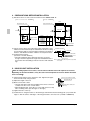
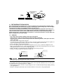
CAUTION
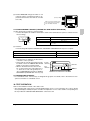
Drain piping connections
Do not connect the drain piping directly to sewage pipes that smell of ammonia. The ammonia in the sewage might enter the indoor unit through the drain pipes and corrode the heat exchanger.
8. ELECTRIC WIRING WORK
8-1 GENERAL INSTRUCTIONS
• All field supplied parts and materials, electric works conform to local codes.
• Use copper wire only.
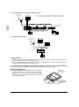
• Follow the “WIRING DIAGRAM” attached to the unitbody to wire the outdoor unit, indoor units and the
remote controller. For details on hooking up the remote controller, refer to the “INSTALLATION MANUAL OF
REMOTE CONTROLLER.”
• All wiring must be performed by an authorized electrician.
• This system consists of multiple indoor units. Mark each indoor unit as unit A, unit B . . . , and be sure the
terminal board wiring to the outdoor unit and HR box are properly matched. If wiring and piping between the
outdoor unit and an indoor unit are mismatched, the system may malfunction.
• A circuit breaker capable of shutting down power supply to the entire system must be installed.
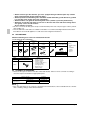
8-2 ELECTRICAL CHARACTERISTICS
Units
Model
Hz
Power supply
Volts
MCA
MFA
kW
FLA
CS-40·50EMHPK
1.3
15
0.100
1.0
CS-63EMHPK
1.5
15
0.160
1.2
2.5
15
0.270
2.0
3.8
15
0.350
3.0
CS-200EMHPK
8.1
15
0.380×2
6.5
CS-250EMHPK
9.0
15
0.380×2
7.2
CS-80·100EMHPK
50
220-240
CS-125EMHPK
MCA: Min. Circuit Amps (A);
kW: Fan Motor Rated Output (kW);
9
Voltage range
Fan motor
Max. 264
Min. 198
MFA: Max. Fuse Amps (A)
FLA: Full Load Amps (A)
English