1
ORDER No. PACD011001C2
Service Manual
Urban Multi
UM Series Using R-407C
Inverter
MX1R Series
Heat Recovery ME1R Series
Combination MA1R Series
UM Series Using R-22
Inverter
MX1 Series
Heat Recovery ME1 Series
WARNIING
This service information is designed for experienced repair technicians only and is not designed for use by the general public.
It does not contain warnings or cautions to advise non-technical individuals of potential dangers in attempting to service a product.
Products powered by electricity should be serviced or repaired only by experienced professional technicians. Any attempt to service or
repair the product or products dealt with in this service information by anyone else could result in serious injury or death.
IMPORTANT SAFETY NOTICE
There are special components used in this equipment which are important for safety. These parts are marked by
in the Schematic
Diagrams, Circuit Board Diagrams, Exploded Views and Replacement Parts List. It is essential that these critical parts should be replaced
with manufacture’s specified parts to prevent shock, fire or other hazards. Do not modify the original design without permission of
manufacture.
Specifications are subject to change without notice for further improvement.
2001 Matsushita Electric Industrial Co., Ltd.
All rights reserved. Unauthorized copying and
distribution is a violation of law.
PACD011001C2
8UEDQ#0XOWL
6HUYLFH#0DQXDO
1. Introduction ...........................................................................................xiii
1.1
1.2
1.3
1.4
Safety Cautions ......................................................................................xiii
Survey of Possible UM Outdoor Units...................................................xvii
Survey of Possible UM Indoor Units..................................................... xviii
Nomenclature ........................................................................................ xix
80#6HULHV#8VLQJ#5055#
,QYHUWHU#0;4#6HULHV#2#
+HDW#5HFRYHU\#0(4#6HULHV# 11111111111111111111111111 4
3DUW4
*HQHUDO#,QIRUPDWLRQ 11111111111111111111111111111111111111111111111111111111111 6
1. Outline of System....................................................................................4
1.1 MX1 Series...............................................................................................4
1.2 Changes in “MX1” Series Functions / Parts .............................................5
1.3 ME1 Series...............................................................................................7
3DUW#5 )XQFWLRQ111111111111111111111111111111111111111111111111111111111111111111111111111111 <
1. Function ................................................................................................10
1.1
1.2
1.3
1.4
1.5
1.6
1.7
1.8
1.9
1.10
1.11
1.12
1.13
1.14
1.15
1.16
1.17
1.18
1.19
1.20
Table of Contents
Outdoor Unit Refrigerant System Diagram.............................................10
List of Safety Devices and Functional Parts Setting Values...................18
Flow of Refrigerant in Each Operation Mode (ME1 Series) ...................20
Outline of Control (ME1 Series) .............................................................25
Safety for Restart ...................................................................................27
Equalized Oil Level Operation
(Equalized Oil Level between Twin Compressors).................................30
Oil Return Operation ..............................................................................31
Defrost....................................................................................................33
Pressure Equalization Control (ME1 Series)..........................................36
Frequency Limit Control by Pressure Equalization (ME1 Series) ..........37
HR Changeover Control (ME1 Series) ...................................................38
Pump Down Residual Operation ............................................................39
Step Down / Safety Control → Standby (Forced Thermostat OFF)
→ Stop Due to Malfunction ....................................................................42
Control During Low Outdoor Air Temperature Cooling ..........................45
Low Noise Control ..................................................................................47
Demand Control .....................................................................................48
Compressor Capacity Control ................................................................49
Te / Tc Setting ........................................................................................50
Gas Depletion Alarm ..............................................................................51
Drain Pump Control................................................................................52
i
PACD011001C2
1.21
1.22
1.23
1.24
3DUW6
Oil Temperature Sensor (8 and 10 Hp only) ..........................................54
Louver Control for Preventing Ceiling Dirt..............................................55
Thermostat Sensor in Remote Controller...............................................56
Freeze Prevention ..................................................................................58
7HVW#2SHUDWLRQ 11111111111111111111111111111111111111111111111111111111111111111 8<
1. Test Operation ......................................................................................60
1.1
1.2
1.3
1.4
1.5
1.6
1.7
1.8
1.9
1.10
1.11
1.12
1.13
1.14
1.15
1.16
1.17
1.18
1.19
1.20
1.21
1.22
1.23
1.24
1.25
Procedure and Outline ...........................................................................60
When Power is Turned On .....................................................................62
Outdoor Unit PC Board Ass’y.................................................................63
Setting Modes (MX1 Series) ..................................................................67
Setting Modes (ME1 Series) ..................................................................73
Sequential Start......................................................................................79
BMS Interface Adaptor for Outdoor Unit (MX1 Series) ..........................80
BMS Interface Adaptor for Outdoor Unit (ME1 Series) ..........................83
Cool / Heat Mode Selection (MX1 Series)..............................................87
Cool / Heat Mode Switching (ME1 Series) .............................................92
Low Noise / Demand Operation (MX1 Series) .......................................94
Low Noise Operation (ME1 Series)........................................................96
Demand Control (ME1 Series) ...............................................................97
Wiring Check Operation .........................................................................98
Indoor Unit PCB Ass’y............................................................................99
Remote Controllers (Wired and Wireless)............................................100
Control by Remote Controller
(Double Remote Controllers, Group, Remote) .....................................106
Indoor Field Setting ..............................................................................108
Centralised Control Group No. Setting.................................................110
Setting of Master Remote Controller ....................................................112
Centralised Control Devices.................................................................114
Central Remote Controller (CZ-01ESM11P) ........................................116
Unified ON/OFF Controller (CZ-01ANA11P)........................................123
Schedule Timer (CZ-01ESW11P) ........................................................126
Combining Different Types of Centralised Control Devices .................130
3DUW#7 7URXEOHVKRRWLQJ 1111111111111111111111111111111111111111111111111111111111111 468
1. Operation Flowcharts ..........................................................................137
1.1 Indoor Unit Operation Flowchart ..........................................................137
1.2 Outdoor Unit Operation Flowchart........................................................142
2. Troubleshooting by Remote Controller ...............................................146
2.1
2.2
2.3
2.4
The INSPECTION / TEST Button.........................................................146
Self-diagnosis by Wired Remote Controller .........................................147
Self-diagnosis by Wireless Remote Controller .....................................148
Operation of The Remote Controller’s Inspection /
Test Operation Button ..........................................................................151
2.5 Remote Controller Service Mode .........................................................152
2.6 Remote Controller Self-Diagnosis Function
(Display of Malfunction Code) ..............................................................154
3. Troubleshooting ..................................................................................156
3.1 Indoor Unit: Error of External Protection Device ..................................156
3.2 Indoor Unit: PC Board Defect...............................................................157
3.3 Indoor Unit: Malfunction of Drain Level Control System (33H).............158
ii
Table of Contents
PACD011001C2
3.4 Indoor Unit: Fan Motor (M1F) Lock, Overload......................................159
3.5 Indoor Unit: Malfunction of Swing Flap Motor (M1S)............................160
3.6 Indoor Unit: Malfunction of Moving Part of
Electronic Expansion Valve (Y1E)........................................................161
3.7 Indoor Unit: Drain Level above Limit ....................................................162
3.8 Indoor Unit: Malfunction of Capacity Determination Device .................163
3.9 Indoor Unit: Malfunction of Thermistor (R2T) for Liquid Pipe ...............164
3.10 Indoor Unit: Malfunction of Thermistor (R3T) for Gas Pipes ................165
3.11 Indoor Unit: Malfunction of Thermistor (R1T) for Air Inlet.....................166
3.12 Indoor Unit: Malfunction of Thermostat Sensor
in Remote Controller ............................................................................167
3.13 Outdoor Unit: Actuation of Safety Device.............................................168
3.14 Outdoor Unit: PC Board Defect ............................................................169
3.15 Outdoor Unit: Actuation of High Pressure Switch.................................170
3.16 Outdoor Unit: Actuation of Low Pressure Switch .................................171
3.17 Outdoor Unit: Malfunction of Moving Part of
Electronic Expansion Valve (Y1E)........................................................172
3.18 Outdoor Unit: Abnormal Discharge Pipe Temperature.........................173
3.19 Outdoor Unit: Malfunction of Thermistor (R1T) for Outdoor Air............174
3.20 Outdoor Unit: Malfunction of Discharge Pipe Thermistor (R3T)...........175
3.21 Outdoor Unit: Malfunction of Thermistor (R4T) for Suction Pipe..........176
3.22 Outdoor Unit: Malfunction of Thermistor (R2T) for Heat Exchanger ....177
3.23 Outdoor Unit: Malfunction of Discharge Pipe Pressure Sensor ...........178
3.24 Outdoor Unit: Malfunction of Suction Pipe Pressure Sensor................179
3.25 Outdoor Unit: Malfunction of Oil Temperature Thermistor (R5T) .........180
3.26 Low Pressure Drop Due to Refrigerant Shortage or
Electronic Expansion Valve Failure......................................................181
3.27 Negative Phase, Open Phase ..............................................................182
3.28 Malfunction of Transmission between Indoor Units..............................183
3.29 Malfunction of Transmission
between Remote Controller and Indoor Unit ........................................184
3.30 Malfunction of Transmission between Outdoor Units...........................185
3.31 Malfunction of Transmission
between Master and Slave Remote Controllers...................................186
3.32 Malfunction of Transmission
between Indoor and Outdoor Units in the Same System .....................187
3.33 Excessive Number of Indoor Units .......................................................188
3.34 Address Duplication of Central Remote Controller...............................189
3.35 Refrigerant System not set, Incompatible Wiring/Piping ......................190
3.36 Malfunction of System, Refrigerant System Address Undefined..........191
4. Failure Diagnosis for Inverter System .................................................192
4.1 Points of Diagnosis...............................................................................192
4.2 How to use the Monitor Switch on the Inverter PC Board ....................193
5. Troubleshooting (Inverter)...................................................................194
5.1 Outdoor Unit: Malfunction of Inverter Radiating
Fin Temperature Rise...........................................................................194
5.2 Outdoor Unit: Inverter Instantaneous Over-Current .............................195
5.3 Outdoor Unit: Inverter Thermostat Sensor, Compressor Overload ......196
5.4 Outdoor Unit: Inverter Stall Prevention, Compressor Lock ..................197
5.5 Outdoor Unit: Malfunction of Transmission
between Inverter and Control PC Board ..............................................198
5.6 Power Supply Insufficient or Instantaneous Failure .............................199
Table of Contents
iii
PACD011001C2
5.7 Outdoor Unit: Inverter Over-Ripple Protection .....................................200
5.8 Outdoor Unit: Malfunction of Inverter Radiating
Fin Temperature Rise Sensor ..............................................................201
6. Troubleshooting (OP: Central Remote Controller) ..............................202
6.1 Malfunction of Transmission
between Central Remote Controller and Indoor Unit ...........................202
6.2 PC Board Defect ..................................................................................203
6.3 Malfunction of Transmission between Optional Controllers
for Centralised Control .........................................................................204
6.4 Improper Combination of Optional Controllers
for Centralised Control .........................................................................205
6.5 Address Duplication, Improper Setting.................................................206
7. Troubleshooting (OP: Schedule Timer)...............................................207
7.1 Malfunction of Transmission
between Central Remote Controller and Indoor Unit ...........................207
7.2 PC Board Defect ..................................................................................208
7.3 Malfunction of Transmission
between Optional Controllers for Centralised Control ..........................209
7.4 Improper Combination of Optional Controllers
for Centralised Control .........................................................................210
7.5 Address Duplication, Improper Setting.................................................211
8. Troubleshooting (OP: Unified ON/OFF Controller) .............................212
8.1 Operation Lamp Blinks .........................................................................212
8.2 Display “Under Host Computer Integrate Control” Blinks
(Repeats Single Blink)..........................................................................213
8.3 Display “Under Host Computer Integrate Control” Blinks
(Repeats Double Blink) ........................................................................215
80#6HULHV#8VLQJ#5073:&##
,QYHUWHU#0;45#6HULHV#2
+HDW#5HFRYHU\#0(45#6HULHV# 11111111111111111111 54:
3DUW#4 *HQHUDO#,QIRUPDWLRQ 1111111111111111111111111111111111111111111111111111111 54<
1. Introduction .........................................................................................220
1.1 Introduction of the Series .....................................................................220
2. Outline.................................................................................................221
2.1 MX1R Series ........................................................................................221
2.2 ME1R Series (Heat Recovery) .............................................................222
2.3 Allowed Range of Indoor Unit and HR Box Connection .......................223
3DUW5
)XQFWLRQ11111111111111111111111111111111111111111111111111111111111111111111111111 558
1. Function ..............................................................................................226
1.1
1.2
1.3
1.4
1.5
iv
Outdoor Unit Refrigerant System Diagram...........................................226
List of Safety Devices and Functional Parts Setting Values.................234
Flow of Refrigerant in Each Operation Mode (ME1R Series)...............236
Outline of Control (ME1R Series).........................................................241
Safety for Restart .................................................................................243
Table of Contents
PACD011001C2
1.6 Equalized Oil Level Operation
(Equalized Oil Level between Twin Compressors)...............................245
1.7 Oil Return Operation ............................................................................246
1.8 Defrost..................................................................................................248
1.9 Pressure Equalization Control (ME1R Series) .....................................251
1.10 Frequency Limit Control by Pressure Equalization (ME1R Series)......252
1.11 HR Changeover Control (ME1R Series) ..............................................253
1.12 Pump Down Residual Operation ..........................................................254
1.13 Step Down / Safety Control → Standby (Forced Thermostat OFF)
→ Stop Due to Malfunction ..................................................................255
1.14 Control During Low Outdoor Air Temperature Cooling ........................258
1.15 Low Noise Control ................................................................................260
1.16 Demand Control ...................................................................................261
1.17 Compressor Capacity Control ..............................................................262
1.18 Te / Tc Setting ......................................................................................263
1.19 Gas Depletion Alarm ............................................................................264
1.20 Drain Pump Control..............................................................................265
1.21 Oil Temperature Sensor (8 and 10 Hp only) ........................................267
1.22 Louver Control for Preventing Ceiling Dirt............................................268
1.23 Thermostat Sensor in Remote Controller.............................................269
1.24 Freeze Prevention ................................................................................271
3DUW#6 7HVW#2SHUDWLRQ 111111111111111111111111111111111111111111111111111111111111111 5:6
1. Test Operation ....................................................................................274
1.1
1.2
1.3
1.4
1.5
1.6
1.7
1.8
1.9
1.10
1.11
1.12
1.13
1.14
1.15
1.16
1.17
Procedure and Outline .........................................................................274
When Power is Turned On ...................................................................276
Outdoor Unit PC Board Ass’y...............................................................277
Setting Modes (MX1R Series)..............................................................281
Setting Modes (ME1R Series)..............................................................288
Sequential Start....................................................................................294
BMS Interface Adaptor for Outdoor Unit (MX1R Series)......................295
BMS Interface Adaptor for Outdoor Unit (ME1R Series)......................298
Cool / Heat Mode Selection (MX1R Series) .........................................302
Cool / Heat Mode Switching (ME1R Series) ........................................309
Low Noise / Demand Operation (MX1R Series)...................................311
Low Noise Operation (ME1R Series) ...................................................313
Demand Control (ME1R Series)...........................................................314
Wiring Check Operation .......................................................................315
Indoor Field Setting ..............................................................................316
Centralised Control Group No. Setting.................................................318
Setting of Master Remote Controller ....................................................320
3DUW#7 7URXEOHVKRRWLQJ 1111111111111111111111111111111111111111111111111111111111111 656
1. Operation Flowcharts ..........................................................................325
1.1 Indoor Unit Operation Flowchart ..........................................................325
1.2 Outdoor Unit Operation Flowchart........................................................330
2. Troubleshooting by Remote Controller ...............................................334
2.1 The INSPECTION / TEST Button.........................................................334
2.2 Self-diagnosis by Wired Remote Controller .........................................335
2.3 Self-diagnosis by Wireless Remote Controller .....................................336
Table of Contents
v
PACD011001C2
2.4 Operation of The Remote Controller’s Inspection /
Test Operation Button ..........................................................................339
2.5 Remote Controller Service Mode .........................................................340
2.6 Remote Controller Self-Diagnosis Function
(Display of Malfunction Code) ..............................................................342
3. Troubleshooting ..................................................................................344
3.1
3.2
3.3
3.4
3.5
3.6
3.7
3.8
3.9
3.10
3.11
3.12
3.13
3.14
3.15
3.16
3.17
3.18
3.19
3.20
3.21
3.22
3.23
3.24
3.25
3.26
3.27
3.28
3.29
3.30
3.31
3.32
3.33
3.34
3.35
3.36
Indoor Unit: Error of External Protection Device ..................................344
Indoor Unit: PC Board Defect...............................................................345
Indoor Unit: Malfunction of Drain Level Control System (33H).............346
Indoor Unit: Fan Motor (M1F) Lock, Overload......................................347
Indoor Unit: Malfunction of Swing Flap Motor (M1S)............................348
Indoor Unit: Malfunction of Moving Part of
Electronic Expansion Valve (Y1E)........................................................349
Indoor Unit: Drain Level above Limit ....................................................350
Indoor Unit: Malfunction of Capacity Determination Device .................351
Indoor Unit: Malfunction of Thermistor (R2T) for Liquid Pipe ...............352
Indoor Unit: Malfunction of Thermistor (R3T) for Gas Pipes ................353
Indoor Unit: Malfunction of Thermistor (R1T) for Air Inlet.....................354
Indoor Unit: Malfunction of Thermostat Sensor
in Remote Controller ............................................................................355
Outdoor Unit: Actuation of Safety Device.............................................356
Outdoor Unit: PC Board Defect ............................................................357
Outdoor Unit: Actuation of High Pressure Switch.................................358
Outdoor Unit: Actuation of Low Pressure Switch .................................359
Outdoor Unit: Malfunction of Moving Part of
Electronic Expansion Valve (Y1E)........................................................360
Outdoor Unit: Abnormal Discharge Pipe Temperature.........................361
Outdoor Unit: Malfunction of Thermistor (R1T) for Outdoor Air............362
Outdoor Unit: Malfunction of Discharge Pipe Thermistor (R3T)...........363
Outdoor Unit: Malfunction of Thermistor (R4T) for Suction Pipe..........364
Outdoor Unit: Malfunction of Thermistor (R2T) for Heat Exchanger ....365
Outdoor Unit: Malfunction of Discharge Pipe Pressure Sensor ...........366
Outdoor Unit: Malfunction of Suction Pipe Pressure Sensor................367
Outdoor Unit: Malfunction of Oil Temperature Thermistor (R5T) .........368
Low Pressure Drop Due to Refrigerant Shortage or
Electronic Expansion Valve Failure......................................................369
Negative Phase, Open Phase ..............................................................370
Malfunction of Transmission Between Indoor Units .............................371
Malfunction of Transmission
Between Remote Controller and Indoor Unit........................................372
Malfunction of Transmission Between Outdoor Units ..........................373
Malfunction of Transmission
Between Master and Slave Remote Controllers ..................................374
Malfunction of Transmission
Between Indoor and Outdoor Units in the Same System.....................375
Excessive Number of Indoor Units .......................................................376
Address Duplication of Central Remote Controller...............................377
Refrigerant System not set, Incompatible Wiring/Piping ......................378
Malfunction of System, Refrigerant System Address Undefined..........379
4. Failure Diagnosis for Inverter System .................................................380
4.1 Points of Diagnosis...............................................................................380
4.2 How to use the Monitor Switch on the Inverter PC Board ....................381
vi
Table of Contents
PACD011001C2
5. Troubleshooting (Inverter)...................................................................382
5.1 Outdoor Unit: Malfunction of Inverter Radiating
Fin Temperature Rise...........................................................................382
5.2 Outdoor Unit: Inverter Instantaneous Over-Current .............................383
5.3 Outdoor Unit: Inverter Thermostat Sensor, Compressor Overload ......384
5.4 Outdoor Unit : Inverter Stall Prevention, Compressor Lock ................385
5.5 Outdoor Unit: Malfunction of Transmission
between Inverter and Control PC Board ..............................................386
5.6 Power Supply Insufficient or Instantaneous Failure .............................387
5.7 Outdoor Unit: Inverter Over-Ripple Protection .....................................388
5.8 Outdoor Unit: Malfunction of Inverter Radiating
Fin Temperature Rise Sensor ..............................................................389
6. Troubleshooting (OP: Central Remote Controller) ..............................390
6.1 Malfunction of Transmission
between Central Remote Controller and Indoor Unit ...........................390
6.2 PC Board Defect ..................................................................................391
6.3 Malfunction of Transmission between Optional Controllers
for Centralised Control .........................................................................392
6.4 Improper Combination of Optional Controllers
for Centralised Control .........................................................................393
6.5 Address Duplication, Improper Setting.................................................394
7. Troubleshooting (OP: Schedule Timer)...............................................395
7.1 Malfunction of Transmission
between Central Remote Controller and Indoor Unit ...........................395
7.2 PC Board Defect ..................................................................................396
7.3 Malfunction of Transmission between Optional Controllers
for Centralised Control .........................................................................397
7.4 Improper Combination of Optional Controllers
for Centralised Control .........................................................................398
7.5 Address Duplication, Improper Setting.................................................399
8. Troubleshooting (OP: Unified ON/OFF Controller) .............................400
8.1 Operation Lamp Blinks .........................................................................400
8.2 Display “Under Host Computer Integrate Control” Blinks
(Repeats Single Blink)..........................................................................401
8.3 Display “Under Host Computer Integrate Control” Blinks
(Repeats Double Blink) ........................................................................403
80#6HULHV#8VLQJ#5073:&#
&RPELQDWLRQ#0;45#6HULHV# 11111111111111111111111 738
3DUW#4 *HQHUDO#,QIRUPDWLRQ 1111111111111111111111111111111111111111111111111111111 73:
1. Product Outline ...................................................................................408
1.1 Year 2001 Models Using New Refrigerant ...........................................408
1.2 Outline of New Series Products ...........................................................409
1.3 Model Configuration and Combination .................................................411
3DUW#5 )XQFWLRQ11111111111111111111111111111111111111111111111111111111111111111111111111 746
1. Outdoor Unit Refrigerant System Diagram .........................................414
Table of Contents
vii
PACD011001C2
1.1 Outdoor Unit Refrigerant System Diagram...........................................414
1.2 Flow of Refrigerant in Each Operating Mode .......................................417
2. List of Safety Device and Function Parts Setting Value......................421
2.1 Outdoor Unit .........................................................................................421
2.2 Indoor Unit............................................................................................422
3. Outline of Control ................................................................................425
3.1 Outdoor Unit .........................................................................................425
3.2 Indoor Unit............................................................................................445
3DUW#6 7HVW#2SHUDWLRQ 111111111111111111111111111111111111111111111111111111111111111 784
1. Test Operation ....................................................................................452
1.1
1.2
1.3
1.4
1.5
1.6
1.7
1.8
1.9
1.10
1.11
1.12
1.13
1.14
Procedure and Outline .........................................................................452
Operation When Power is Turned On ..................................................454
Outdoor Unit PC Board Ass’y...............................................................455
Setting Modes ......................................................................................457
Cool / Heat Mode Selection..................................................................464
Low Noise Operation............................................................................469
Demand Control ...................................................................................470
Sequential Start....................................................................................471
Wiring Check Operation .......................................................................472
Additional Refrigerant Charge Operation .............................................473
Refrigerant Recovery Mode .................................................................474
Indoor Field Setting ..............................................................................475
Centralised Control Group No. Setting.................................................477
Contents of Control Modes...................................................................479
3DUW#7 7URXEOHVKRRWLQJ 1111111111111111111111111111111111111111111111111111111111111 7;4
1. Operation Flowcharts ..........................................................................483
1.1 Indoor Unit Operation Flowchart ..........................................................483
2. Troubleshooting by Remote Controller ...............................................488
2.1
2.2
2.3
2.4
The INSPECTION / TEST Button.........................................................488
Self-diagnosis by Wired Remote Controller .........................................489
Self-diagnosis by Wireless Remote Controller .....................................490
Operation of The Remote Controller’s Inspection /
Test Operation Button ..........................................................................493
2.5 Remote Controller Service Mode .........................................................494
2.6 Remote Controller Self-Diagnosis Function
(Display of Malfunction Code) ..............................................................496
3. Troubleshooting ..................................................................................498
3.1
3.2
3.3
3.4
3.5
3.6
3.7
3.8
3.9
3.10
viii
Indoor Unit: Error of External Protection Device ..................................498
Indoor Unit: PC Board Defect...............................................................499
Indoor Unit: Malfunction of Drain Level Control System (33H).............500
Indoor Unit: Fan Motor (M1F) Lock, Overload......................................501
Indoor Unit: Malfunction of Swing Flap Motor (M1S)............................502
Indoor Unit: Malfunction of Moving Part of
Electronic Expansion Valve (Y1E)........................................................503
Indoor Unit: Drain Level above Limit ....................................................504
Indoor Unit: Malfunction of Capacity Determination Device .................505
Indoor Unit: Malfunction of Thermistor (R2T) for Liquid Pipe ...............506
Indoor Unit: Malfunction of Thermistor (R3T) for Gas Pipes ................507
Table of Contents
PACD011001C2
3.11 Indoor Unit: Malfunction of Thermistor (R1T) for Air Inlet.....................508
3.12 Indoor Unit: Malfunction of Thermostat Sensor
in Remote Controller ............................................................................509
3.13 Outdoor Unit: Actuation of Safety Device.............................................510
3.14 Outdoor Unit: PC Board Defect ............................................................511
3.15 Outdoor Unit: Actuation of High Pressure Switch.................................512
3.16 Outdoor Unit: Actuation of Low Pressure Switch .................................513
3.17 Outdoor Unit: Malfunction of Moving Part of
Electronic Expansion Valve (Y1E)........................................................514
3.18 Outdoor Unit: Abnormal Discharge Pipe Temperature.........................515
3.19 Outdoor Unit: Malfunction of Thermistor (R1T) for Outdoor Air............516
3.20 Outdoor Unit: Malfunction of Discharge Pipe Thermistor (R3T)...........517
3.21 Outdoor Unit: Malfunction of Thermistor (R4T) for Suction Pipe..........518
3.22 Outdoor Unit: Malfunction of Thermistor (R2T) for Heat Exchanger ....519
3.23 Outdoor Unit: Malfunction of Discharge Pipe Pressure Sensor ...........520
3.24 Outdoor Unit: Malfunction of Suction Pipe Pressure Sensor................521
3.25 Low Pressure Drop Due to Refrigerant Shortage or
Electronic Expansion Valve Failure......................................................522
3.26 Negative Phase, Open Phase ..............................................................523
3.27 Malfunction of Transmission Between Indoor Units .............................524
3.28 Malfunction of Transmission
Between Remote Controller and Indoor Unit........................................525
3.29 Malfunction of Transmission Between Outdoor Units ..........................526
3.30 Malfunction of Transmission
Between Master and Slave Remote Controllers ..................................527
3.31 Malfunction of Transmission
Between Indoor and Outdoor Units in the Same System.....................528
3.32 Excessive Number of Indoor Units .......................................................529
3.33 Address Duplication of Central Remote Controller...............................530
3.34 Refrigerant System not Set, Incompatible Wiring/Piping......................531
3.35 Malfunction of System, Refrigerant System Address Undefined..........532
4. Failure Diagnosis for Inverter System .................................................533
4.1 Points of Diagnosis...............................................................................533
4.2 How to Use The Monitor Switch on The Inverter PC Board .................534
5. Troubleshooting (Inverter)...................................................................535
5.1 Outdoor Unit: Malfunction of Inverter Radiating
Fin Temperature Rise...........................................................................535
5.2 Outdoor Unit: Inverter Instantaneous Over-Current .............................536
5.3 Outdoor Unit: Inverter Thermostat Sensor, Compressor Overload ......537
5.4 Outdoor Unit: Inverter Stall Prevention, Compressor Lock ..................538
5.5 Outdoor Unit: Malfunction of Transmission
Between Inverter and Control PC Board ..............................................539
5.6 Power Supply Insufficient or Instantaneous Failure .............................540
5.7 Outdoor Unit: Inverter Over-Ripple Protection .....................................541
5.8 Outdoor Unit: Malfunction of Inverter Radiating
Fin Temperature Rise Sensor ..............................................................542
6. Troubleshooting (OP: Central Remote Controller) ..............................543
6.1 Malfunction of Transmission
Between Central Remote Controller and Indoor Unit ...........................543
6.2 PC Board Defect ..................................................................................544
6.3 Malfunction of Transmission
Between Optional Controllers for Centralised Control..........................545
Table of Contents
ix
PACD011001C2
6.4 Improper Combination of Optional Controllers
for Centralised Control ........................................................................546
6.5 Address Duplication, Improper Setting.................................................547
7. Troubleshooting (OP: Schedule Timer)...............................................548
7.1 Malfunction of Transmission Between Central
Remote Controller and Indoor Unit.......................................................548
7.2 PC Board Defect ..................................................................................549
7.3 Malfunction of Transmission
Between Optional Controllers for Centralised Control..........................550
7.4 Improper Combination of Optional Controllers
for Centralised Control .........................................................................551
7.5 Address Duplication, Improper Setting.................................................552
8. Troubleshooting (OP: Unified ON/OFF Controller) .............................553
8.1 Operation Lamp Blinks .........................................................................553
8.2 Display “Under Host Computer Integrate Control” Blinks
(Repeats Single Blink)..........................................................................554
8.3 Display “Under Host Computer Integrate Control” Blinks
(Repeats Double Blink) ........................................................................556
3DUW#8 6SHFLDO#6HUYLFH#0RGH11111111111111111111111111111111111111111111111111111 88:
1. Backup and Emergency Operation .....................................................558
1.1 Backup and Emergency Operation ......................................................558
2. Pump Down Operation........................................................................560
2.1 Pump Down Operation .........................................................................560
$SSHQGL[1111111111111111111111111111111111111111111111111111111111111111111111111111111111111 894
1. Wiring Diagrams (Outdoor Unit)..........................................................562
1.1
1.2
1.3
1.4
1.5
MX1 Series...........................................................................................562
ME1 Series (Heat Recovery)................................................................564
MX1R Series ........................................................................................566
ME1R Series (Heat Recovery) .............................................................568
MA1R Series (Combination).................................................................570
2. Wiring Diagrams (Indoor Unit).............................................................572
2.1
2.2
2.3
2.4
2.5
2.6
2.7
2.8
2.9
2-Way Cassette Type...........................................................................572
4-Way Cassette Type...........................................................................574
Corner Type .........................................................................................575
Built-In Type .........................................................................................576
Ducted Type .........................................................................................578
Ceiling Type .........................................................................................580
Wall Type .............................................................................................581
Floor Standing Type / Concealed Floor Standing Type .......................582
Small Duct Type ...................................................................................583
3. Characteristics ....................................................................................584
3.1
3.2
3.3
3.4
R407C Characteristics .........................................................................584
Thermistor Resistance / Temperature Characteristics .........................585
Pressure Sensor...................................................................................587
Method of Replacing The Inverter’s Power Transistors and
Diode Modules .....................................................................................588
4. Precaution ...........................................................................................590
4.1 PC Boards and Remote Controller’s Mode No.....................................590
x
Table of Contents
PACD011001C2
5. Typical Wiring Mistakes ......................................................................591
5.1 Typical Wiring Mistakes........................................................................591
6. Interface Adaptor.................................................................................598
6.1 BMS Interface Adaptor for Unified Group (KRP2A51·52) ....................598
6.2 BMS Interface Adaptor for Individual and Unified Control
(KRP4A51 / KRP4A52 / KRP4A53)......................................................603
6.3 Signal Output Adaptor PCB for Optional Accessory
(KRP1B61 / KRP1B2 / KRP1B3)..........................................................606
6.4 Interface Adaptor for Urban Split Series (CZ-102AP11P) ....................608
6.5 Interface Adaptor for Other Air Conditioners (CZ-103AP11P) .............610
6.6 BMS Interface Adaptor for Outdoor Units
(DTA104A51 · DTA104A52).................................................................613
6.7 BMS Interface Adaptor (DCS302A52)..................................................616
7. Precautions in Servicing The Models with New-type Refrigerant .......620
7.1 Tools Required .....................................................................................620
7.2 Notes for Work Procedures ..................................................................621
Table of Contents
xi
PACD011001C2
xii
Table of Contents
PACD011001C2
Introduction
1. Introduction
1.1
Safety Cautions
Cautions and
Warnings
1.1.1
„ Be sure to read the following safety cautions before conducting repair work.
Warning” and “
Caution”. The “
Warning” items are
„ The caution items are classified into “
especially important since they can lead to death or serious injury if they are not followed closely. The
“
Caution” items can also lead to serious accidents under some conditions if they are not followed.
Therefore, be sure to observe all the safety caution items described below.
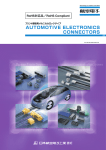
„ About the pictograms
This symbol indicates an item for which caution must be exercised.
The pictogram shows the item to which attention must be paid.
This symbol indicates a prohibited action.
The prohibited item or action is shown inside or near the symbol.
This symbol indicates an action that must be taken, or an instruction.
The instruction is shown inside or near the symbol.
„ After the repair work is complete, be sure to conduct a test operation to ensure that the equipment
operates normally, and explain the cautions for operating the product to the customer
Cautions in Repair
Warning
Be sure to disconnect the power cable plug from the plug socket before disassembling
the equipment for a repair.
Working on the equipment that is connected to a power supply can cause an electrical
shook.
If it is necessary to supply power to the equipment to conduct the repair or inspecting the
circuits, do not touch any electrically charged sections of the equipment.
If the refrigerant gas discharges during the repair work, do not touch the discharging
refrigerant gas.
The refrigerant gas can cause frostbite.
When disconnecting the suction or discharge pipe of the compressor at the welded
section, release the refrigerant gas completely at a well-ventilated place first.
If there is a gas remaining inside the compressor, the refrigerant gas or refrigerating
machine oil discharges when the pipe is disconnected, and it can cause injury.
If the refrigerant gas leaks during the repair work, ventilate the area. The refrigerant gas
can generate toxic gases when it contacts flames.
The step-up capacitor supplies high-voltage electricity to the electrical components of the
outdoor unit.
Be sure to discharge the capacitor completely before conducting repair work.
A charged capacitor can cause an electrical shock.
Do not start or stop the air conditioner operation by plugging or unplugging the power
cable plug.
Plugging or unplugging the power cable plug to operate the equipment can cause an
electrical shock or fire.
xiii
Introduction
PACD011001C2
Caution
Do not repair the electrical components with wet hands.
Working on the equipment with wet hands can cause an electrical shock.
Do not clean the air conditioner by splashing water.
Washing the unit with water can cause an electrical shock.
Be sure to provide the grounding when repairing the equipment in a humid or wet place,
to avoid electrical shocks.
Be sure to turn off the power switch and unplug the power cable when cleaning the
equipment.
The internal fan rotates at a high speed, and cause injury.
Do not tilt the unit when removing it.
The water inside the unit can spill and wet the furniture and floor.
Be sure to check that the refrigerating cycle section has cooled down sufficiently before
conducting repair work.
Working on the unit when the refrigerating cycle section is hot can cause burns.
Use the welder in a well-ventilated place.
Using the welder in an enclosed room can cause oxygen deficiency.
1.1.2
Cautions Regarding Products after Repair
Warning
Be sure to use parts listed in the service parts list of the applicable model and appropriate
tools to conduct repair work. Never attempt to modify the equipment.
The use of inappropriate parts or tools can cause an electrical shock, excessive heat
generation or fire.
When relocating the equipment, make sure that the new installation site has sufficient
strength to withstand the weight of the equipment.
If the installation site does not have sufficient strength and if the installation work is not
conducted securely, the equipment can fall and cause injury.
Be sure to install the product correctly by using the provided standard installation frame. For integral units only
Incorrect use of the installation frame and improper installation can cause the equipment
to fall, resulting in injury.
Be sure to install the product securely in the installation frame mounted on a window
frame.
If the unit is not securely mounted, it can fall and cause injury.
Be sure to use an exclusive power circuit for the equipment, and follow the technical
standards related to the electrical equipment, the internal wiring regulations and the
instruction manual for installation when conducting electrical work.
Insufficient power circuit capacity and improper electrical work can cause an electrical
shock or fire.
Be sure to use the specified cable to connect between the indoor and outdoor units.
Make the connections securely and route the cable properly so that there is no force
pulling the cable at the connection terminals.
Improper connections can cause excessive heat generation or fire.
xiv
For integral units only
PACD011001C2
Introduction
Warning
When connecting the cable between the indoor and outdoor units, make sure that the
terminal cover does not lift off or dismount because of the cable.
If the cover is not mounted properly, the terminal connection section can cause an
electrical shock, excessive heat generation or fire.
Do not damage or modify the power cable.
Damaged or modified power cable can cause an electrical shock or fire.
Placing heavy items on the power cable, and heating or pulling the power cable can
damage the cable.
Do not mix air or gas other than the specified refrigerant (R22) in the refrigerant system.
If air enters the refrigerating system, an excessively high pressure results, causing
equipment damage and injury.
If the refrigerant gas leaks, be sure to locate the leak and repair it before charging the
refrigerant. After charging refrigerant, make sure that there is no refrigerant leak.
If the leak cannot be located and the repair work must be stopped, be sure to perform
pump-down and close the service valve, to prevent the refrigerant gas from leaking into
the room. The refrigerant gas itself is harmless, but it can generate toxic gases when it
contacts flames, such as fan and other heaters, stoves and ranges.
When replacing the coin battery in the remote controller, be sure to disposed of the old
battery to prevent children from swallowing it.
If a child swallows the coin battery, see a doctor immediately.
Caution
Installation of a leakage breaker is necessary in some cases depending on the conditions
of the installation site, to prevent electrical shocks.
Do not install the equipment in a place where there is a possibility of combustible gas
leaks.
If a combustible gas leaks and remains around the unit, it can cause a fire.
Be sure to install the packing and seal on the installation frame properly.
If the packing and seal are not installed properly, water can enter the room and wet the
furniture and floor.
1.1.3
For integral units only
Inspection after Repair
Warning
Check to make sure that the power cable plug is not dirty or loose, then insert the plug
into a power outlet all the way.
If the plug has dust or loose connection, it can cause an electrical shock or fire.
If the power cable and lead wires have scratches or deteriorated, be sure to replace
them.
Damaged cable and wires can cause an electrical shock, excessive heat generation or
fire.
Do not use a joined power cable or extension cable, or share the same power outlet with
other electrical appliances, since it can cause an electrical shock, excessive heat
generation or fire.
Caution
Check to see if the parts and wires are mounted and connected properly, and if the
connections at the soldered or crimped terminals are secure.
Improper installation and connections can cause excessive heat generation, fire or an
electrical shock.
xv
Introduction
PACD011001C2
Caution
If the installation platform or frame has corroded, replace it.
Corroded installation platform or frame can cause the unit to fall, resulting in injury.
Check the grounding, and repair it if the equipment is not properly grounded.
Improper grounding can cause an electrical shock.
Be sure to measure the insulation resistance after the repair, and make sure that the
resistance is 1 Mohm or higher.
Faulty insulation can cause an electrical shock.
Be sure to check the drainage of the indoor unit after the repair.
Faulty drainage can cause the water to enter the room and wet the furniture and floor.
xvi
PACD011001C2
1.2
Introduction
Survey of Possible UM Outdoor Units
UM outdoor units are available in 5 to 30HP format to precisely meet the needs of any building size.
Modular design enables UM outdoor units to be joined together in rows with an outstanding degree of
uniformity. The design of the UM Inverter & heat recovery series is sufficiently compact to be taken to the
top of building in a commercial elevator, overcoming site transportation problems.
Refrigerant
Type
Outdoor Unit
CU-5MX1SPP
Inverter
Maximum n° of Connectable indoor units
8
13
R-407C
Combination Inverter
R-22
32
Range of Total
Capacity Index
62.5~162.5
100~260
{
125~325
{
100~260
{
CU-10ME1XPK
125~325
PA-16MA1XPK
{
PA-18MA1XPK
{
225~585
PA-20MA1XPK
{
250~650
200~520
PA-24MA1XPK
{
300~780
PA-26MA1XPK
{
325~845
PA-28MA1XPK
{
350~910
PA-30MA1XPK
{
375~975
CU-8MX1SPE
{
62.5~162.5
{
CU-8ME1XNA
CU-10ME1XNA
100~260
{
CU-10MX1SPE
Heat Recovery
30
{
CU-8ME1XPK
CU-5MX1SPE
Inverter
20
{
CU-8MX1SPP
CU-10MX1SPP
Heat Recovery
16
{
125~325
100~260
{
125~325
xvii
Introduction
1.3
PACD011001C2
Survey of Possible UM Indoor Units
Refrigerant
R-407C
R-22
Type
Model Name
25
32
40
50
63
80
100
125
200
250
2-Way Cassette Type
CS-LMHPP
{
{
{
{
{
{
{
—
{
—
—
4-Way Cassette Type
CS-UMHPP
{
{
{
{
{
{
{
{
{
—
—
Corner Type
CS-DM1HPK
—
{
{
{
—
{
—
—
—
—
—
Built-in Type
CS-FMHPP
{
{
{
{
{
{
{
{
{
—
—
Small Duct Type
CS-NM1HPP
{
{
—
—
—
—
—
—
—
—
—
Ducted Type
CS-EMHPK
—
—
—
{
{
{
{
{
{
{
{
Ceiling Type
CS-TMJPL
—
—
{
—
—
{
—
{
—
—
—
Wall Type
CS-KM1HPK
{
{
{
{
{
{
—
—
—
—
—
Floor Standing Type
CS-PM1HPK
{
{
{
{
{
{
—
—
—
—
—
Cancealed Floor
Standing Type
CS-RM1HPK
{
{
{
{
{
{
—
—
—
—
—
20
25
31.25
40
50
62.5
80
100
125
200
250
Capacity Index
eg.
xviii
Size
20
Selected indoor units:
CS-25LMHPP + CS-100LMHPP + CS-200EMHPK+ CS-40FMHPP
Connection ratio:
25 + 100 + 200 + 40 = 365
Possible outdoor unit:
PA-16MA1XPK
PACD011001C2
Introduction
1.4
Nomenclature
1.4.1
Outdoor Unit
CU
8
M
X
1
S
P
P
Refrigerant etc.
K~P : R-407C
A~E : R-22
Destination
P : Europe
Power supply
S, X : 3φ, 400V, 50Hz
Type
X : Inverter heat pump
E : Heat recovery inverter
A : Combination inverter : main unit
B : Combination inverter : sub unit
M : Urban Multi (UM)
Capacity
5 : 5HP
8 : 8HP
10 : 10HP
16 : 16HP
20 : 20HP
24 : 24HP
26 : 26HP
28 : 28HP
30 : 30HP
CU : Outdoor Unit
CS : Indoor Unit
CZ : Accessories
PA : Combinationed Outdoor Unit
(
)
(M201)
xix
Introduction
1.4.2
PACD011001C2
Indoor Unit
CS
125
U
M
H
P
P
Refrigerant etc.
K~P : R-407C / R-22
Destination
P : Europe
Power supply
H : 1φ, 230V, 50Hz
M : Urban Multi (UM)
Type
L : 2-way cassette type
U : 4-way cassette type
D : Corner type
F : Built-in type
N : Small duct type
E : Ducted type
T : Ceiling type
K : Wall type
P : Floor standing type
R : Concealed floor standing type
Capacity
20 : 0.8HP
25 :
1HP
32 : 1.25HP
40 : 1.6HP
50 : 2.0HP
63 : 2.5HP
80 : 3.2HP
100 :
4HP
125 :
5HP
200 :
8HP
250 : 10HP
CS : Indoor Unit
CU : Outdoor Unit
CZ : Accessories
(
)
(M200)
xx
PACD011001C2
80#6HULHV#8VLQJ#5055#
0;4#6HULHV
,QYHUWHU
+HDW#5HFRYHU\ 0(4#6HULHV
Urban Multi “MX1, ME1 Series” Using R-22
1
PACD011001C2
2
Urban Multi “MX1, ME1 Series” Using R-22
PACD011001C2
3DUW4
*HQHUDO#,QIRUPDWLRQ
1. Outline of System....................................................................................4
1.1 MX1 Series...............................................................................................4
1.2 Changes in “MX1” Series Functions / Parts .............................................5
1.3 ME1 Series...............................................................................................7
General Information Urban Multi “MX1, ME1 Series” Using R-22
3
Outline of System
PACD011001C2
1. Outline of System
1.1
MX1 Series
1.1.1
Urban Multi Inverter MX1 Series System Outline
4
General Information Urban Multi “MX1, ME1 Series” Using R-22
PACD011001C2
Outline of System
1.2
Changes in “MX1” Series Functions / Parts
1.2.1
Changes in the System as a Whole
More outdoor units
can be connected.
A maximum of 16 indoor units can now be connected to a single system.
5HP .......... 8 units
8HP .......... 13 units
10HP ........ 16 units
Same wiring can be
used for
transmission
between indoor/
outdoor units and
centralised control
Up to now, separate wiring was required for centralised control and for transmission between indoor/
outdoor units when installing optional controllers for centralised control, but now the same wiring can be
used for both. This facilitates indoor/outdoor transmission wiring construction work as follows.
MX1 Series
‹ Same terminals used for input and output.
‹ No polarity.
‹ 3 wiring methods can be used (serial, bus and star wiring).
‹ Up to 16 branches can be used. (Cannot be branched again once branched.)
‹ System wiring can be up to a total of 2,000 meters.
(Max. wiring length up to 1,000 meters).
„ Indoor unit terminal block
MX1
Series
Remote controller
N
Transmission
wiring
P
F1
External
F2
T1
T2
„ Outdoor unit terminal block
MX1
Series
C / H selector
A
B
To In / D unit
C
F1
F2
To Out / D unit
F1
F2
2 central remote
controller can be
connected in a
transmission
system.
UM Inverter MX1 Series equipment can be connected with two central remote controllers, and can
individual control 128 unit (64 units T 2) on a single transmission line.
Change in Mode of
Transmission
Between Outdoor
Units
Wiring for transmission between outdoor units is necessary for selecting cool or heat mode for several units
at once. This transmission has been changed as follows.
MX1 Series
‹ Same terminals used for input and output.
‹ Sequential start requires only wiring between outdoor units and setting.
‹ Simultaneous cool/heat selection and low noise operation require a separate adaptor for outside control
of outdoor units.
‹ Transmission can be conducted between a maximum of 10 units.
‹ Optional controllers for centralised control can be connected to a transmission line between outdoor
units.
General Information Urban Multi “MX1, ME1 Series” Using R-22
5
Outline of System
PACD011001C2
UM Inverter MX1
Series
Outdoor unit
Indoor
Outdoor
-outdoor -outdoor
Indoor
Outdoor
-outdoor -outdoor
Indoor
Outdoor
-outdoor -outdoor
F1
F1
F1
F2 F1
F2
F2 F1
F2
F2 F1
F2
To other outdoor unit
To indoor unit
Indoor unit
N
P
F1
F2
N
P
F1
F1
F2
F2
N
P
F1
P
F1
F2
F2
Individual remote controller
N
P
F1
F2
N
P
F1
F2
N
P
N
Central remote controller
(VL002)
1.2.2
Changes in Indoor Units
Drain Pump
When the TEST OPERATION button has been pushed in order to facilitate checking drainage when
installing, the drain pump is force-operated regardless of the temperature control mode. If a humidifier is to
be included in the setup, you must set to “Equipped humidifier” with the remote controller. (With the factory
settings, the drain pump is not operated during heating.)
Swing Louver
The wall mounted type is equipped with a swing louver. The ceiling mounted cassette type can be set to
prevent the ceiling from being soiled.
Able to Use
Wireless Remote
Controllers
The multi flow, double flow, ceiling suspended and wall mounted types can be fitted with a wireless remote
controller kit.
(Other types can use a separate wireless remote controller.)
1.2.3
Changes in Outdoor Units
Equipped with Oil
Temperature
Sensor Thermistor
(8 and 10HP)
6
Oil temperature detection has been incorporated into control in order to prevent wet operation and improve
dilution of oil.
General Information Urban Multi “MX1, ME1 Series” Using R-22
PACD011001C2
Outline of System
1.3
ME1 Series
1.3.1
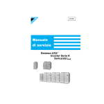
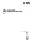
System Outline
„ Allows individual control of different types of indoor units with varying capacities totaling 50 to 130% of
the outdoor unit capacity.
∗ When total indoor capacity exceeds 100%, indoor unit operating capacity may decrease slightly if all
indoor units are operated at the same time.
„ Indoor units ranging from the smallest 20 type (0.8 HP).
„ Flexible refrigerant piping: equivalent length of 125 m, actual length of 100 m, outdoor unit height
difference of 50 m, and height difference of 15 m between indoor units.
System outline & operation mode
HR box
CU-10ME
(10HP)
2.5 HP or
equivalent
2.5 HP or
equivalent
2.5 HP or
equivalent
2.5 HP or
equivalent
No. 1
No. 2
No. 3
No. 4
Outdoor unit
Indoor unit
(A) All units in cooling operation
Heat radiation
Cooling
Cooling
Cooling
Cooling
(B) Most units in cooling operation. and a few units in heating operation
Heat radiation
Cooling
Cooling
Cooling
Heating
(C) Most units in heating operation, and a few units in cooling operation
Heat absorption
Cooling
Heating
Heating
Heating
Heating
Heating
Heating
Heating
(D) All units in heating operation
Heat absorption
(M102)
∗
Outside temperature of 35°C for operation mode (A), 0°C for operation mode (D), and typical seasonal
outside temperatures for others.
General Information Urban Multi “MX1, ME1 Series” Using R-22
7
Outline of System
1.3.2
PACD011001C2
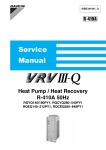
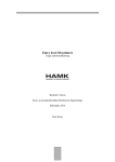
Allowed Range of Indoor Unit and HR Box Connection
Range A
Range B
HR box
Range C
Range C
Range C
Range C
Indoor unit
( Cooling
only unit )
( Cooling
only unit )
(M103)
„ Arrange systems to conform below conditions referring to above diagram.
Range
Item
Model of outdoor
unit and HR box
Range A Total indoor unit capacity
Range B Total indoor unit capacity
allowed for simultaneous
cooling/heating operations
Range C Total indoor unit capacity
allowed for connection to HR box
8
Total capacity of
connectable indoor
units
Max. number of
connectable indoor
units
CU-8ME1XPA
11.2 to 29.1kW
13 units
CU-10ME1XPA
14 to 36.4kW
16 units
CU-8ME1XPA
11.2kW or more
13 units
CU-10ME1XPA
14kW or more
16 units
CZ-100HR1HE
less than 11.2kW
5 units or less
CZ-160HR1HE
11.2 to 18kW
6 units or less
General Information Urban Multi “MX1, ME1 Series” Using R-22
PACD011001C2
3DUW#5
)XQFWLRQ
1. Function ................................................................................................10
1.1
1.2
1.3
1.4
1.5
1.6
1.7
1.8
1.9
1.10
1.11
1.12
1.13
1.14
1.15
1.16
1.17
1.18
1.19
1.20
1.21
1.22
1.23
1.24
Outdoor Unit Refrigerant System Diagram.............................................10
List of Safety Devices and Functional Parts Setting Values...................18
Flow of Refrigerant in Each Operation Mode (ME1 Series) ...................20
Outline of Control (ME1 Series) .............................................................25
Safety for Restart ...................................................................................27
Equalized Oil Level Operation
(Equalized Oil Level between Twin Compressors).................................30
Oil Return Operation ..............................................................................31
Defrost....................................................................................................33
Pressure Equalization Control (ME1 Series)..........................................36
Frequency Limit Control by Pressure Equalization (ME1 Series) ..........37
HR Changeover Control (ME1 Series) ...................................................38
Pump Down Residual Operation ............................................................39
Step Down / Safety Control → Standby (Forced Thermostat OFF)
→Stop Due to Malfunction .....................................................................42
Control During Low Outdoor Air Temperature Cooling ..........................45
Low Noise Control ..................................................................................47
Demand Control .....................................................................................48
Compressor Capacity Control ................................................................49
Te / Tc Setting ........................................................................................50
Gas Depletion Alarm ..............................................................................51
Drain Pump Control................................................................................52
Oil Temperature Sensor (8 and 10 Hp only) ..........................................54
Louver Control for Preventing Ceiling Dirt..............................................55
Thermostat Sensor in Remote Controller...............................................56
Freeze Prevention ..................................................................................58
Function Urban Multi “MX1, ME1 Series” Using R-22
9
Function
PACD011001C2
1. Function
1.1
Outdoor Unit Refrigerant System Diagram
1.1.1
CU-5MX1SPE
10
Function Urban Multi “MX1, ME1 Series” Using R-22
PACD011001C2
Function
A. Compressor M1C
Scroll compressor that operates on 30~116Hz by inverter drive enables 13-step capacity control.
Capacity control is carried out for individual and linear control of indoor units.
B. Oil separator
The oil separator is a device that collects the oil discharged from the compressor.
The collected oil is constantly recycled to the compressor via capillary tube.
C. Solenoid valve (hot gas bypass) Y2S
Valve is opened by low pressure safety control when low pressure drops.
Balances high/low pressure when off in order to reduce load when the compressor starts.
D. Outdoor unit electronic expansion valve Y1E
Expansion valve when heating. Senses compressor suction pipe and low pressure equivalent saturated
temperature, and carries out superheat degree control.
E. Solenoid valve (injection) Y3S
Controls injection in order to prevent overheating.
F. Heat exchange pipe
Subcooling so that refrigerant drift doesn’t occur between indoor units when flash gas is produced in the
liquid pipe.
G. Pressure sensor (high pressure, red) SENPH
Semiconductor pressure sensor for sensing the operating status of the indoor by refrigerant pressure which
senses discharge pressure.
H. Pressure sensor (low pressure, blue) SENPL
Semiconductor pressure sensor for sensing the operating status of the indoor by refrigerant pressure which
senses suction pressure.
Function Urban Multi “MX1, ME1 Series” Using R-22
11
Function
1.1.2
PACD011001C2
CU-8·10MX1SPE
SENPH
STD
SENPL
INV
4D014597
12
Function Urban Multi “MX1, ME1 Series” Using R-22
PACD011001C2
Function
A. Compressor M1C / M2C
Connecting a scroll compressor (inverter compressor) that operates on 30~116Hz by inverter drive and a
scroll compressor (standard compressor) that runs on a commercial power supply to the same refrigerant
system enables 21-step capacity control. Capacity control is carried out for individual and linear control of
indoor units.
(M1C: Inverter compressor, M2C: Standard compressor)
C. Check valve
Keeps liquid refrigerant from collecting in the standard compressor when only the inverter compressor is
running.
D. Oil separator
The oil separator is a device that collects the oil discharged from the compressor. The collected oil is
constantly recycled to the compressor via capillary tube.
E. Solenoid valve (hot gas bypass) Y2S
Valve is opened by low pressure safety control when low pressure drops. Balances high/low pressure
when off in order to reduce load when the compressor starts.
F. Outdoor unit electronic expansion valve Y1E
Expansion valve when heating. Senses compressor suction pipe and low pressure equivalent saturated
temperature, and carries out superheat degree control.
G. Solenoid valve (injection) Y3S / Y4S
Controls injection in order to prevent overheating.
Y3S: Inverter compressor, Y4S: Standard compressor
I. Pressure sensor (high pressure, red) SENPH
Semiconductor pressure sensor for sensing the operating status of the indoor by refrigerant pressure which
senses discharge pressure.
J. Pressure sensor (low pressure, blue) SENPL
Semiconductor pressure sensor for sensing the operating status of the indoor by refrigerant pressure which
senses suction pressure.
Function Urban Multi “MX1, ME1 Series” Using R-22
13
Function
1.1.3
14
PACD011001C2
CU-8·10ME1XPA (Heat Recovery)
Function Urban Multi “MX1, ME1 Series” Using R-22
PACD011001C2
Function
A. Compressor
The 20-step capacity control is achieved by the inverter scroll compressor that uses an inverter for
frequency control in a range of 30 to 116 Hz and the standard scroll compressor that uses commercial
power supply. The compressors allow individual control of indoor units and linear control.
(M1C : inverter compressor, M2C : standard compressor)
B. Oil separator
This device collects oil discharged from the compressors. The device receives oil and sends recovered oil
to the compressors through the capillary tube.
C. Solenoid valve (for hot gas bypass) Y2S
This valve maintains balance between the high and low pressure sides when the equipment stops, thus
reducing compressor load in the next startup.
This valve is activated by a low-pressure protection control function and opens when the low-pressure side
decreases in pressure.
D. Outdoor unit electronic expansion valves Y1E, Y2E
These expansion valves are activated during heating operation.
They detect the compressor suction pipe temperature and low pressure equivalent saturation temperature
and control superheat.
(Y1E : for primary-side heat exchanger, Y2E : for secondary-side heat exchanger)
E. Solenoid valve (injection) Y3S, Y4S
Controls injection solenoid valve ON-OFF in order to prevent overheating.
Y3S : for inverter side compressor
Y4S : for standard side compressor
F. Solenoid valve (discharge gas) Y5S, Y7S
Valve is opened during heating and simultaneous cooling and heating operations.
G. Solenoid valve (for pressure equalization) Y1S
This valve maintains pressure balance before and after the HR box solenoid valve during cooling and
heating operation mode change.
H. Solenoid valve (for liquid pressure) Y6S
This valve opens a bypass to send hot gas to the receiver and controls the liquid pressure.
I. Pressure sensor (high pressure ··· red) SENPH
This semiconductor pressure sensor detects discharge pressure. The detected refrigerant pressure is used
to evaluate the operation conditions of indoor units.
Heating operation ··· The sensor detects high pressure and controls the compressor capacity.
J. Pressure sensor (low pressure ··· blue) SENPL
This semiconductor pressure sensor detects suction pressure. The detected refrigerant pressure is used to
evaluate the operation conditions of indoor units.
Cooling operation ··· The sensor detects low pressure and controls the compressor capacity.
Heating operation ··· The sensor provides superheat control.
K. 4-way valves Y1R, Y2R
(Y1R : for primary-side heat exchanger, Y2R: for secondary-side heat exchanger)
1. Outside temperature thermistor R1T
Heating operation ··· Used as a function of defrost IN condition.
The thermostat turns off when the temperature exceeds 23°C.
2. Coil temperature thermistors R2-1T, R2-2T
(R2-1T : for primary-side heat exchanger, R2-2T : for secondary-side heat exchanger)
Cooling operation ··· Not used.
Heating operation ··· Used as a function of defrost IN condition, in combination with the outside temperature
data.
3. Discharge temperature thermistors R3-1T, R3-2T
These thermistors are used for compressor discharge temperature protection.
(R3-1T : inverter compressor, R3-2T : standard compressor)
4. Suction pipe temperature thermistors R4-1T, R4-2T
These thermistors are used for compressor discharge temperature protection.
(R4-1T : for primary-side heat exchanger, R4-2T : for secondary-side heat exchanger)
5. Oil temperature thermistor R5T
During defrost and oil return operation, provides upper-limit frequency control to improve oil diluting
condition.
Function Urban Multi “MX1, ME1 Series” Using R-22
15
Function
1.1.4
PACD011001C2
HR Box
CZ-100HR1HE
A. Solenoid valve (suction side) Y2S
This solenoid valve turns ON when normal cooling operation and discharge/suction oil return operation.
(Connect indoor unit gas pipe and outdoor unit suction pipe.)
B. Solenoid valve (discharge side) Y3S
Turn ON this valve to operate of discharge oil return when indoor unit is set for heating. (Connect indoor
unit gas pipe and outdoor unit discharge pipe.)
C. Solenoid valve (Drift prevention injection) Y1S
The only valve in HR box of which indoor unit is in heating operation when simultaneous cooling/heating
operation is applied in the same system
∗ Impossible to replace solenoid valve main body.
16
Function Urban Multi “MX1, ME1 Series” Using R-22
PACD011001C2
1.1.5
Function
Function of Thermistors and Pressure Sensors
Outdoor Unit
CU-8·10MX1SPE
Function Urban Multi “MX1, ME1 Series” Using R-22
17
Function
PACD011001C2
1.2
List of Safety Devices and Functional Parts Setting Values
1.2.1
CU-5·8·10MX1SPE
Item
Symbol
Name
Type
CU-5MX1SPE
Compressor
Safety
device
Inverter
side Model
Output
3φ,
380~415V
INV
CU-10MX1SPE
JT100BAVTYE
3.5 kW
JT100BAVTYE
3.5 kW
JT100BATYE
2.2 kW
JT160BATYE
3.75kW
Compressor safety thermostat
Discharge pipe thermistor 135°C OFF
J1HC/
J2HC
Crank case heater
33W
F2C
Over-current
relay
Q1M
Q2M
Fan motor
190W
140W+230W
Safety thermostat
Open 135°C ± 5°C
140W: Open 120 ± 5°C, 230W: 135 ± 5°C
S1P
Pressure switch (for high
pressure safety)
20SP-688-6
OFF: 27.5+0~-1.0kg/cm²
ON: 20.0+1.0~-1.0kg/cm²
S1PH
Pressure switch (for high
pressure safety)
—
20SP-688-6 OFF: 27.5+0~-1.0kg/cm2
ON: 20.0+1.0~-1.0kg/cm²
S2PH
Pressure switch (for high
pressure safety)
—
20SP-688-6 OFF: 27.5+0~-1.0kg/cm2
ON: 20.0+1.0~-1.0kg/cm²
3φ, 380~415V
33W+33W
—
HOE-20F-TRA1
10A
FPG-3D 70~75°C
PS8030A 0~30kg/cm² (0~2.94MPa)
SENPL Pressure sensor
PS8030A 0~10kg/cm² (0~0.98MPa)
R1T
Thermistor (for outdoor air)
3.5~360KΩ
R2T
Thermistor
(for heat exchange)
3.5~360KΩ
R3T
Thermistor
(for discharge pipe)
3.5~400KΩ
R3-1T
Thermistor (for inverter discharge
pipe)
—
3.5~400KΩ
R3-2T
Thermistor (for standard
discharge pipe)
—
3.5~400KΩ
R4T
Thermistor
(for suction pipe)
R5T
Thermistor
for inverter oil temperature)
—
3.5~400KΩ
Electronic
expansion valve
—
3.5~360KΩ
When
cooling
ON: 2,000 pulses (completely open); OFF: 0 pulses (completely closed)
When
heating
ON: PI control; OFF: 0 pulses (completely closed)
Y2S
Solenoid valve
(for hot gas bypass)
NEV603
Y3S
Solenoid valve
(for inverter injection)
NEV202
Y4S
Solenoid valve
(for standard injection)
—
NEV202
Y1S
Note 1
Solenoid valve
(pressure equalizing)
—
NEV202
Note
HOE-20F-TRA1
13A
—
SENPH Pressure sensor
Other
Y1E
functions Note 1
/parts
18
3.5 kW
STD
Fusible plug
Sensor
JT100BAVYE
CU-8MX1SPE
1. These parts are for heat pump model only.
Function Urban Multi “MX1, ME1 Series” Using R-22
PACD011001C2
1.2.2
Item
Function
CU-8·10ME1XPA
Symbol
Name
Type
CU-8ME1XPA
Compressor
Safety
device
Inverter
side Model
Output
3φ,
380~415V
JT100BAVTYE
3.5 kW
JT100BAVTYE
3.5 kW
STD
JT100BATYE
2.2 kW
JT160BATYE
3.75kW
Compressor safety thermostat
Discharge pipe thermistor 135°C OFF
J1HC/
J2HC
Crank case heater
33W+33W
F2C
Over-current
relay
Q1M
Q2M
Fan motor
Safety thermostat
140W: Open 120 ± 5°C, 230W: 135 ± 5°C
S1PH
Pressure switch (for high
pressure safety)
20SP-688-6 OFF: 27.5+0~–1.0kg/cm2
ON: 20.0+1.0~–1.0kg/cm²
S2PH
Pressure switch (for high
pressure safety)
20SP-688-6 OFF: 27.5+0~–1.0kg/cm2
ON: 20.0+1.0~–1.0kg/cm²
3φ, 380~415V HOE-20F-TRA1
10A
HOE-20F-TRA1
13A
140W+230W
Fusible plug
Sensor
CU-10ME1XPA
INV
FPG-3D 70~75°C
SENPH Pressure sensor
PS8030A 0~30kg/cm² (0~2.94MPa)
SENPL Pressure sensor
PS8030A 0~10kg/cm² (0~0.98MPa)
R1T
Thermistor (for outdoor air)
3.5~360KΩ
R2-1T
R2-2T
Thermistor
(for heat exchange)
3.5~360KΩ
R3-1T
Thermistor (for inverter discharge
pipe)
3.5~400KΩ
R3-2T
Thermistor (for standard
discharge pipe)
3.5~400KΩ
R4-1T
R4-2T
Thermistor
(for suction pipe)
3.5~360KΩ
R5T
Thermistor
for inverter oil temperature)
3.5~360KΩ
Electronic
expansion valve
ON: 2,000 pulses (Fully open); OFF: 0 pulses (Fully closed)
Other
Y1E
functions
/parts
When
cooling
When
ON: PI control; OFF: 0 pulses (Fully closed)
heating
Y1S
Solenoid valve
(pressure equalizing)
BPV1706
Y2S
Solenoid valve
(for hot gas bypass)
NEV603
Y3S
Solenoid valve
(for inverter injection)
NEV202
Y4S
Solenoid valve
(for standard injection)
NEV202
Y5S
Y7S
Solenoid valve
(for discharge gas)
NEV603
Y6S
Solenoid valve
(for liquid pressure)
NEV603
Function Urban Multi “MX1, ME1 Series” Using R-22
19
Function
PACD011001C2
Flow of Refrigerant in Each Operation Mode (ME1 Series)
1.3.1
Cooling
High pressure
Low pressure
1.3
20
Function Urban Multi “MX1, ME1 Series” Using R-22
PACD011001C2
Heating
High pressure
Low pressure
1.3.2
Function
Function Urban Multi “MX1, ME1 Series” Using R-22
21
Function
Simultaneous Cooling and Heating
High pressure
Low pressure
1.3.3
PACD011001C2
22
Function Urban Multi “MX1, ME1 Series” Using R-22
PACD011001C2
Discharge Oil Return, Defrost
High pressure
Low pressure
1.3.4
Function
Function Urban Multi “MX1, ME1 Series” Using R-22
23
Function
Suction Oil, Defrost
High pressure
Low pressure
1.3.5
PACD011001C2
24
Function Urban Multi “MX1, ME1 Series” Using R-22
PACD011001C2
Function
1.4
Outline of Control (ME1 Series)
1.4.1
Inverter Compressor, Motorized PI Control
1. Compressor PI control
„ Cooling operation
Controls TeS (target Te value) at constant ··· Constant-level control of Te (low pressure equivalent
saturation temperature)
TeS = 5.5°C
„ Heating operation
Controls TcS (target Tc value) at constant ··· Constant-level control of Tc (high pressure equivalent
saturation temperature)
TcS = 48°C
„ Simultaneous cooling/heating operations
Controls TeS and TcS at constant
TeS = 5.5°C
TcS = 48°C
∗ TeS setting values
L
M
(Factory setting)
H
2.5
5.5
8.5
L
M
(Factory setting)
H
43
46
49
* TcS setting values
2. Motorized valve PI control
Provides PI control for the motorized valves (Y1E and Y2E) to maintain a constant superheat (SH) level at
the outlet of the outdoor heat exchanger (evaporator).
SHs = Ts - Te
SHs = 5°C
∗ Ts1 :Suction pipe temperature (R4-1T)
Ts2: Suction pipe temperature (R4-2T)
3. Heat exchanger PI control
Provides PI control for the motorized valve (Y1E) to maintain TeS and TcS at constant.
Motorized valve mode
EV mode
1
2
3
4
5
Initial opening
Max. opening
Min. opening
Normal opening
Y1E
2000
2000
2000
Y2E
2000
2000
2000
Fixed at 2000
Fixed at 2000
Y1E
2000
2000
1400
Heat exchanger PI control
Y2E
0
0
0
Y1E
750
1400
100
Heat exchanger PI control
Y2E
250
400
100
Motorized valve PI control
Y1E
0
0
0
Y2E
700
1000
100
Motorized valve PI control
Y1E
700
2000
100
Motorized valve PI control
Y2E
500
2000
100
Motorized valve PI control
Function Urban Multi “MX1, ME1 Series” Using R-22
Fixed at 0
Fixed at 0
25
Function
PACD011001C2
Heat exchanger mode
Heat exchanger 1
Heat exchanger 2
FAN
EV mode
Cooling operation
COND
COND
H + ON
1
↑
↓
Heat operation
COND
COND
L + ON
1
COND
COND
H + OFF
1
COND
COND
L + OFF
1
COND
EVAP
H + ON
2
COND
EVAP
L + ON
2
COND
EVAP
H + OFF
2
COND
EVAP
L + OFF
2
COND
EVAP
L + OFF
3
COND
EVAP
L + OFF
4
COND
EVAP
H + OFF
4
COND
EVAP
H + ON
4
4
EVAP
EVAP
L + OFF
EVAP
EVAP
H + OFF
4
EVAP
EVAP
H + ON
4
EVAP
EVAP
H + ON
5
COND: Condenser
EVAP: Evaporator
26
Function Urban Multi “MX1, ME1 Series” Using R-22
PACD011001C2
Function
1.5
Safety for Restart
1.5.1
Restart Safety Timer
The compressor will not run for five minutes by making forced thermostat OFF condition in order to prevent
it from being turned on and off in rapid succession, and to equalize pressure in the refrigerant circuit. It
however restarts automatically after five minutes passes if it is in thermostat ON condition. The pressure
equalizing solenoid valve is actuated for 10 minutes (15 minutes for 8 and 10HP heating only) after the
compressor stops in order to equalize pressure.
Thermostat
Thermostat ON
Thermostat
OFF
Thermostat ON
Thermostat ON
Thermostat OFF
ON
ON
ON
OFF
Compressor
OFF
5 minutes
ON
ON
OFF
ON
OFF
Pressure equalizing
solenoid valve
1 minute
(Soft start)
Linear control
1000 pulses
Fully closed
0 pulses
Indoor unit
electronic expansion
valve (when heating)
OFF
OFF
1 minute 1 minute
(Pressure (Soft start)
equalizing)
Linear control
1000 pulses
240 pulses
10 minutes
(15 minutes for
8.10 HP heating only)
Linear control
Fully closed
0 pulses
5 minutes
(VL005)
(10 minutes
for 8 and 10 HP)
If 10 minutes or more has elapsed since the compressor was turned off (15 minutes for 8 and 10HP heating
only) , turn the solenoid valve for equalizing pressure on for about 1 minute and equalize the pressure.
When heating, to prevent noise produced by the passing of indoor unit’s refrigerant to equalize pressure
after the compressor stops, fully close the indoor unit’s electronic expansion valve for 5 minutes (10
minutes for 8 and 10HP).
1.5.2
Soft Start
The following control is carried out to protect the compressor and inverter.
1. Operates at low frequency (fixed) for 1 minute after compressor starts. (Prevents liquid refrigerant
backflow)
2. Pressure equalizing and hot gas bypass solenoid valves open and start low load.
Compressor frequency
Soft Start of
Compressor
42Hz
1 minute when started
Time
(VG001)
Frequency during soft start
CU-5
42Hz
CU-8·10
42Hz+OFF
Function Urban Multi “MX1, ME1 Series” Using R-22
27
Function
1.5.3
PACD011001C2
Pump Down Start
If the compressor stops running with refrigerant still remaining in the accumulator, in order to prevent wet
operation at the next compressor starting, it will perform pump down start with a completely dry
accumulator, then it will operate normally.
Pump down start should be performed if the unit is in any of the conditions given below when pressure
equalizing control has been completed before start.
If R3T (R3-1T) is less than 95°C and the unit is in any of the following conditions.
‹ Within 10 minutes of the compressor starting
‹ Defrosting or during oil return
‹ Within 20 minutes of completion of defrost or oil return
‹ Outdoor air temperature is less than -5°C (MX1 Series)
‹ Outdoor air temperature (R1T) < 0ºC (ME1 Series)
‹ Oil temperature (R5T) < Te + 10ºC (ME1 Series)
Te : Low pressure equivalent saturated temperature
Operation During
Pump Down Start
MX1 Series
1 min.
5 min.
42Hz
(42Hz+OFF)
42Hz
(42Hz+OFF)
42Hz
(42Hz+OFF) Note 1
30~106 Hz+OFF
PI control ∗ Note 2
Outdoor unit EV
0 pulses
0 pulses
0 pulses
SH control (Initial
opening 150 pulses)
Outdoor unit fan
H tap (H+ON)
H tap (H+ON)
Compressor
Note
← 11 min. 30 sec. →
H tap (H+ON)
H tap (H+ON)
Y2S
ON
ON
Y3S, Y4S
ON
30 sec.
ON
30 sec.
OFF
4 min. 30 sec.
ON/OFF
(LP protection control)
ON/OFF
ON/OFF
ON/OFF
(Td protection control) (Td protection control) (Td protection control)
1. Note 1: 30Hz (30Hz+OFF) for products produced after Aug. ‘99.
2. ∗Note 2 : When heating, low pressure < 1.5 kg/cm² (0.147MPa) → running frequency 54Hz (54Hz +
OFF)
Low pressure > 1.7 kg/cm² (0.167MPa) [30 sec. continuous] → release
‹ Y2S: Hot gas bypass solenoid valve
‹ Y3S: Injection solenoid valve
ME1 Series
← 11 min. 30 sec. →
1 min.
5 min.
42Hz+OFF
42Hz+OFF
30Hz+OFF
Outdoor unit EV
0 pulses
0 pulses
0 pulses
150 pulses
Outdoor unit fan
H tap (H+ON)
H tap (H+ON)
H tap (H+ON)
H tap (H+ON)
Y2S
ON
ON
Y3S
ON
Compressor
30 sec.
ON
30 sec.
OFF
4 min. 30 sec.
116Hz+OFF
ON/OFF
(LP protection control)
ON/OFF
ON/OFF
ON/OFF
(Td protection control) (Td protection control) (Td protection control)
‹ Y2S: Hot gas bypass solenoid valve
‹ Y3S: Injection solenoid valve
28
Function Urban Multi “MX1, ME1 Series” Using R-22
PACD011001C2
1.5.4
Function
Heating Lay-Up Start
If the compressor hasn’t run for a long time and the refrigerant isn’t circulated, foaming could cause a lack
of oil when the compressor is started at the next time. It should therefore perform heating lay-up start to
keep the low pressure from dropping too low in the following cases.
‹ When, after being power ON, the accumulated running time of the compressor does not exceed one
hour.
‹ When the compressor has been stopped for more than 24 hours.
Operation During
Heating Lay-Up
Start
Make the compressor’s upper limit frequency 60Hz (60Hz+OFF) for 10 minutes 20 seconds after the
compressor starts.
∗ If the low pressure becomes < 1.5kg/cm² (0.147MPa) within 10 minutes after starting, Y2S is actuated
and outdoor unit EV becomes 0 pulses. 10 minutes after start, the unit starts up as described below.
(8,10 Hp)
4 min. 30 sec.
Compressor
PI control (upper limit 116Hz [116Hz+OFF]) ∗
Outdoor unit EV
SH control (initial opening 150 pulses)
Outdoor unit fan
H tap (H+ON)
Y2S
ON/OFF (LP safety control)
Y3S
ON/OFF (Td safety control)
‹ Y2S: Hot gas bypass solenoid valve
‹ Y3S: Injection solenoid valve
∗ If low pressure becomes < 1.5 kg/cm² (0.147MPa), operating frequency becomes 54Hz.
If low pressure becomes > 1.7 kg/cm² (0.167MPa), the heating lay-up operation is released.
Function Urban Multi “MX1, ME1 Series” Using R-22
29
Function
1.6
PACD011001C2
Equalized Oil Level Operation
(Equalized Oil Level between Twin Compressors)
If using two compressors (8, 10Hp) connected in parallel, oil level equalizing is carried out for 5 minutes
when the cumulative running time of the standard compressor exceeds 2 hours in order to prevent lack of
oil caused by difference in pressure inside the dome due to drift, and then reverts to normal operation.
Inverter compressor
Standard compressor
106Hz
OFF
∗ If oil pressure equalization is not achieved during 5 minutes by stopping or step-down control, oil pressure
equalization is carried out when the compressor starts running.
With an inverter compressor operation, however, if the standard compressor remains off for 10 minutes,
the cumulative running time of the standard compressor is reset.
30
Function Urban Multi “MX1, ME1 Series” Using R-22
PACD011001C2
Function
1.7
Oil Return Operation
1.7.1
MX1 Series
In order to collect refrigeration oil held up in connecting piping, the compressor’s operating time is counted,
and oil return operation is carried out for 4 minutes every 8 hours (2 hour after turning on the power supply,
and every 8 hours after that).
(When heating, the indoor unit’s electric heater is tuned off one minute prior to oil return operation in
preparation for oil return.)
1. Compressor Operation Frequency
Type
Cool
Heat
CU-5 (5HP)
106Hz
96Hz
CU-8 (8HP)
106Hz+ON
86Hz+ON
CU-10 (10HP)
106Hz+ON
86Hz+ON
‹ When heating, frequency is lower than that given in the table for the first 30 seconds and 30 seconds
after completion.
‹ Frequency may drop according to the various types of step-down control. If so, the next oil return must
be carried out 4 hours later.
2. Opening of the Electronic Expansion Valve
Outdoor unit
Operating indoor unit
Indoor unit turned off
When cooling
2000 pulses (fully open)
2000 pulses (fully open)
1440 pulses
When heating
2000 pulses (fully open)
2000 pulses (fully open)
2000 pulses (fully open)
3. 4-way Changeover Valve (Y1R)
When cooling: No change
When heating: Switches to cooling mode
4. Fan and Solenoid Valve
Step No. changes according to high pressure.
Step No.
Y2S
Y3S, Y4S
Fan
1
ON∗
ON
H(H+ON)
2
OFF∗∗
ON
L(H+OFF)
3
OFF∗∗
ON
OFF
(Step No. becomes higher as high pressure decreases.)
Step 1 → Step 2 30 sec. after oil return start or high pressure < 16kg/cm² (1.57MPa)
Step 2 → Step 3 High pressure < 7.5 kg/cm² (0.74MPa)
Step 3 → Step 2 High pressure > 15 kg/cm² (1.47MPa)
Step 2 → Step 1 High pressure > 20 kg/cm² (1.96MPa)
∗ When heating only
∗∗ On when low pressure < 0.3 kg/cm² (0.029MPa)
Off when low pressure > 0.8 kg/cm² (0.078MPa)
Notes:
1. If the compressor frequency continues at 68Hz (38Hz+ON for 8, 10HP) or more for more than eight
minutes with defrosting while the oil return timer is counting, the timer is reset and counts again for eight
hours.
2. If on standby (forced thermostat OFF) or the compressor stops due to malfunction during oil return
operation, the next time the compressor starts, oil return operation is again carried out for four minutes
after completion of soft start.
3. Oil return operation is not carried out for 28 minutes after defrosting is completed.
Function Urban Multi “MX1, ME1 Series” Using R-22
31
Function
1.7.2
PACD011001C2
ME1 Series
In order to collect refrigeration oil held up in connecting piping, the compressor’s operating time is counted,
and oil return operation is carried out for 8 minutes 30 seconds every 8 hours (2 hour after turning on the
power supply, and every 8 hours after that).
(When heating, the indoor unit’s electric heater is tuned off one minute prior to oil return operation in
preparation for oil return.)
Operation Contents
Step 1 → Discharge oil return
1 Minute
Elapses
Preparation
for Oil Return
k = kg/cm²
Compressor
86Hz + OFF
EEV
2000pls
Outdoor Unit Fan
H + ON
Outdoor Unit Heat Exchanger
Upper Limit Frequency
Limited to 38Hz + ON
Condenser
4 Way Valve
(VF014)
OFF
Injection 1
Td Protection Control
Injection 2
OFF
Hot Gas
ON at Lp < 0.3k
4 Minutes Elapsed
Step 2 → Suction oil return
Compressor
86Hz + OFF
EEV
2000pls
Outdoor Unit Fan
H + ON
Outdoor Unit Heat Exchanger
Condenser
4 Way Valve
OFF
Injection 1
Td Protection Control
Injection 2
Td Protection Control
Hot Gas
ON at Lp < 0.3k
4 Minutes Elapsed
∗ Td : Discharge Pipe Temperature
Step 3 → HR solenoid valve changeover
Compressor
38Hz + OFF
EEV
2000pls
Outdoor Unit Fan
H + ON
Outdoor Unit Heat Exchanger
Condenser
4 Way Valve
OFF
Injection 1
Td Protection Control
Injection 2
OFF
Hot Gas
ON at Lp < 0.3k
30 Seconds Elapsed
Step 4 → Refrigerant is discharged from accumulator
Compressor
76Hz + OFF
EEV
Limit of Opening
Outdoor Unit Fan
H + ON
Outdoor Unit Heat Exchanger
Evaporater
4 Way Valve
ON
Injection 1
Td Protection Control
Injection 2
Hot Gas
OFF
Low Pressure Protection Control
5 Minutes Elapsed
Hp > 14k
R5T > Te + 10ºC
* Te : Low Pressure Equivalent
Saturated Temperature
Normal Control
32
Function Urban Multi “MX1, ME1 Series” Using R-22
PACD011001C2
1.8
Defrost
1.8.1
MX1 Series
Function
„ Function
Defrost operation is carried out if the relation of the outdoor unit’s coil temperature (Tcoil) and outdoor
temperature (Tair) satisfies the conditions given below for 5 minutes continuously.
Tcoil ≤ C · Tair- α
• Tcoil
• Tair
: Temperature detected by R2T
•C
: Tair < 0°C → 0.8
Tair ≥ 0°C → 0.6
: Temperature detected by R1T
The values of (α) according to defrost temperature changeover switch are given in the table below.
Switch position
LED (23 24 25 26)
L
(O OýO {)
M
(O O { O)
H
(O { O O)
(deg)
12
10
8
Therefore, if outdoor temperature is 0°C:
(1) If position L, Tcoil ≤ -12°C
(2) If position M, Tcoil ≤ -10°C
(3) If position H, Tcoil ≤ -8°C
Because defrost operation is carried out, set to the “H” position if frost builds up easily, and set to “L” if not.
Factory set is position “M.”
Defrost is carried out when the coil temperature rises to 12.5ºC or higher, and is completed after defrosting
for 10 minutes. After defrosting, indoor units carry out hot start operation and the DEFROSTING display
lights until hot start is complete.
Defrost conditions are not counted from completion of power supply set-up and defrost until the
compressor runs (count) for 20 minutes.
T coil
12.5ºC
06.Tair · U
20 minutes
Power supply set-up
5 minutes
Defrost start
20 minutes
Complete
5 minutes
10 minutes
Defrost start
Complete
(VG002)
Function Urban Multi “MX1, ME1 Series” Using R-22
33
Function
1.8.2
PACD011001C2
ME1 Series
Melts frost which might collect on outdoor heat exchangers during heating in order to recover their heat
transfer performance.
Conditions for executing defrost
At least 20 minutes have elapsed since completion of oil return or since compressor starts.
&
High pressure < 20k (Tc = 52.4ºC)
Compressor is running at least 30 minutes since completion of previous defrost.
Either liquid pipe thermal detection temperature (R2-1T, R2-2T) < TºC for 5 minutes.
OR
Forced defrost test pin (MDS) is shorted.
&
Liquid pipe thermal detection temperature (R2-1T, R2-2T) < 12.5ºC for all units
High pressure < 20k (Tc = 52.4ºC)
∗ Tc : High pressure equivalent saturated temperature
T = C × (Outdoor temp.) – α
(C is constant)
C : Tair ≤ 0°C → 0.8
Tair > 0°C → 0.6
∗ Tair = Outdoor air temperature
The values of (α) according to defrost temperature changeover switch are given in the table below.
Switch position
LED (H4P, H5P, H6P, H7P)
L
(O OýO {)
M
(O O { O)
H
(O { O O)
(deg)
12
10
8
Therefore, if outdoor temperature is 0°C:
(1) If position L, Tcoil (R2-1T, R2-2T) ≤ -12°C
(2) If position M, Tcoil (R2-1T, R2-2T) ≤ -10°C
(3) If position H, Tcoil (R2-1T, R2-2T) ≤ -8°C
Because defrost operation is carried out, set to the “H” position if frost builds up easily, and set to “L” if not.
Factory set is position “M.”
34
Function Urban Multi “MX1, ME1 Series” Using R-22
PACD011001C2
Function
Operation Contents
Step 1 → Discharge defrost
Preparation
for Defrost
1 Minute
Elapses
Upper Limit Frequency
Limited to 38Hz + ON
k = kg/cm²
Compressor
86Hz + OFF
EEV
2000pls
Outdoor Unit Fan
OFF + OFF
Outdoor Unit Heat Exchanger
Condenser
4 Way Valve
(VF015)
OFF
Injection 1
Td Protection Control
Injection 2
OFF
Hot Gas
ON
3 Minutes Elapsed
Step 2 → Suction defrost
Compressor
86Hz + ON
EEV
2000pls
Outdoor Unit Fan
OFF + OFF
Outdoor Unit Heat Exchanger
Condenser
4 Way Valve
OFF
Injection 1
Td Protection Control
Injection 2
Td Protection Control
Hot Gas
ON
Conclusion of Defrost Completion
Condition
or
All of R2-1T, R2-2T ≥ 12.5ºC
Pc > 20.5k
10 Minutes Elapsed Since
Defrost Operation Start
Step 3 → HR solenoid valve changeover
Compressor
38Hz + OFF
EEV
2000pls
Outdoor Unit Fan
OFF + OFF
Outdoor Unit Heat Exchanger
Condenser
4 Way Valve
OFF
Injection 1
Td Protection Control
Injection 2
OFF
Hot Gas
ON
40 Seconds Elapsed
Step 4 → Refrigerant is discharged from accumulator
Compressor
76Hz + OFF
EEV
Limit of EV Opening
Outdoor Unit Fan
H + ON
Outdoor Unit Heat Exchanger
Evaporator
4 Way Valve
ON
Injection 1
Td Protection Control
Injection 2
Hot Gas
OFF
Low Pressure Protection Control
5 Minutes Elapsed
or Pc > 14k
R5T > Te + 10ºC
Normal Control
∗Pc = Condensing Pressure
Function Urban Multi “MX1, ME1 Series” Using R-22
35
Function
1.9
PACD011001C2
Pressure Equalization Control (ME1 Series)
The discharge gas and suction gas pipes are bypassed to eliminate differential pressure between the inlet
and outlet of the solenoid valve during HR box(e)s solenoid switching operations.
„ Equalizing operation demand → Pressure equalization solenoid valve (Y1S) is ON at following
conditions.
Operating condition of indoor unit with thermostat ON is different from the condition of HR boxes’ solenoid
valve (see page 38).
Not in startup control.
Liquid refrigerant not being discharged from accumulator.
&
Not in residual pump-down operation.
7 minutes passed after completion of previous pressure equalizing control operation.
Not in oil return control
Not in defrost operation
36
Function Urban Multi “MX1, ME1 Series” Using R-22
PACD011001C2
1.10
Function
Frequency Limit Control by Pressure Equalization (ME1 Series)
The compressor operating capacity is limited to prevent abnormal noise caused by the equalizing
operation.
Operating conditions
&
Equalizing operation demand issued
Not in cooling operation only
During the first 30 seconds, the following operations are conducted.
INV outdoor unit
Compressor operating capacity
Function Urban Multi “MX1, ME1 Series” Using R-22
54Hz + OFF
37
Function
1.11
PACD011001C2
HR Changeover Control (ME1 Series)
The solenoid valve of the HR box is switched according to the indoor unit operating condition.
Normal operation
Cooling
Condition 1
Heating
Condition 2
Oil return, defrost
Oil return, defrost
Condition 3
Discharge defrost
Discharge oil return
Condition 4
Suction defrost
Suction oil return
Oil return, defrost complete
(VF006)
Condition
Indoor unit operating condition
Y3S
Y2S
Y1S
1
Cooling
Heating stop ∗1
OFF
ON
OFF
2
Heating thermostat OFF
Heating thermostat ON
ON
OFF
∗2
3
Discharge oil return
OFF
OFF
OFF
4
Suction oil return
Defrost
ON
ON
OFF
ON: Open
OFF: Closed
When the solenoid is operable, if the operating condition differs from the solenoid condition, the solenoid is
switched according to the above table.
However, the following conditions take precedence.
∗1 : Condition 2 results in heating stop units when no unit in the system is in cooling operation.
∗2 : Condition 1 results when a unit connected to the HR box is in heating thermostat ON condition
during simultaneous cooling/heating operations.
38
Function Urban Multi “MX1, ME1 Series” Using R-22
PACD011001C2
1.12
Function
Pump Down Residual Operation
1.12.1 MX1 Series
If refrigerant is remaining in the accumulator when the compressor starts, liquid refrigerant is sucked into
the compressor, diluting the refrigerant machine oil and reducing the lubricating performance. To prevent
this, the pump-down operation discharges refrigerant from the low pressure side when the unit is not in
operation.
Residual operation may be carried out for 10 minutes under the following conditions when heating.
1. When outdoor temperature (R1T) is ≥ -5°C and inverter discharge pipe temperature (R3-1T) < 95ºC,
and a OFF by thermostat command is received with the compressor’s continuous operation time being
10 minutes or less, residual operation is carried out for a maximum of 10 minutes.
Discharge pipe thermistor (R3-1T) on inverter side: 95°C or lower
Outside air temperature thermistor (R1T) < 0°C
&
OR
When compressor continuous operating time is less than 10 minutes and thermostat is OFF, or
when stop command is received from remote controller
Within 20 minutes after defrost or oil return operation
T0 (oil temperature) ≤ Te+10
Max. 10 min.
ON
Thermostat
OFF
Compressor and
outdoor unit fan
ON
OFF
Residual operation for 10 min.
Operation may stop during the 10 minutes
residual operation due to protection discharge,
high/low pressure, etc.
(VL006)
2. When the thermostat is ON during residual operation, residual operation is not carried out if the total of
1+2+3 is 10 minutes or more.
Max. 10 min.
Max. 10 min.
ON
Thermostat
OFF
1
Residual
2 operation
3
ON
Compressor and
outdoor unit fan
OFF
Residual operation not carried out
if 1 + 2 + 3 is 10 minutes or more.
Thermostat
ON
(VL007)
3. When outdoor temperature (R1T) < -5°C and a stop command is received from the thermostat sensor,
etc., residual operation is carried out for 10 minutes without fail. (Operation may however stop for
discharge pipe or high/low pressure safety.)
Function Urban Multi “MX1, ME1 Series” Using R-22
39
Function
PACD011001C2
Outdoor Unit
Function
Outdoor air (R1T)
Compressor
INV
Notes
Electronic
expansion valve
STD
Pressure equalizing
solenoid valve
Time
R1T < -10°C
86Hz
OFF
0~300 pulses
ON or OFF
10 min.
-10°C ≤ R1T < 0°C
76Hz
OFF
0~300 pulses
ON or OFF
10 min.
R1T ≥ 0°C
60Hz
OFF
0~300 pulses
ON or OFF
10 min.
„ During defrost or oil return, residual operation is not carried out even if a stop command comes.
„ Forced thermostat OFF occurs if defrost or oil return signal comes during residual operation.
1.12.2 ME1 Series
If refrigerant is remaining in the accumulator when the compressor starts, liquid refrigerant is sucked into
the compressor, diluting the refrigerant machine oil and reducing the lubricating performance. To prevent
this, the pump-down operation discharges refrigerant from the low pressure side when the unit is not in
operation.
Residual operation may be carried out for Max.10 minutes under the following conditions.
1.
Secondary side heat exchanger 4 way valve (Y2R) is ON.
Discharge pipe thermistor (R3-1T) on inverter side: 95°C or lower
Outside air temperature thermistor (R1T) < 0°C
&
OR
When compressor continuous operating time is less than 10 minutes and thermostat is OFF, or
when stop command is received from remote controller
Within 20 minutes after defrost or oil return operation
R5T (oil temperature) ≤ Te+15
Max. 10 min.
ON
Thermostat
OFF
Compressor and
outdoor unit fan
Operation may stop during the 10 minutes
residual operation due to protection discharge,
high/low pressure, etc.
ON
OFF
Residual operation for 10 min.
(VL006)
2. When the thermostat is ON during residual operation, residual operation is not carried out if the total of
1+2+3 is 10 minutes or more.
Max. 10 min.
Max. 10 min.
ON
Thermostat
OFF
1
Residual
2 operation
3
ON
Compressor and
outdoor unit fan
OFF
Residual operation not carried out
if 1 + 2 + 3 is 10 minutes or more.
40
Thermostat
ON
(VL007)
Function Urban Multi “MX1, ME1 Series” Using R-22
PACD011001C2
Outdoor Unit
Function
Function
Outdoor air (R1T)
Compressor
INV
Notes
STD
Electronic expansion
valve
Time
R1T < -10°C
86Hz
OFF
0~300 pulses
10 min.
-10°C ≤ R1T < 0°C
76Hz
OFF
0~300 pulses
10 min.
R1T ≥ 0°C
60Hz
OFF
0~300 pulses
10 min.
„ During defrost or oil return, residual operation is not carried out even if a stop command comes.
„ Forced thermostat OFF occurs if defrost or oil return signal comes during residual operation.
Function Urban Multi “MX1, ME1 Series” Using R-22
41
Function
1.13
PACD011001C2
Step Down / Safety Control → Standby (Forced Thermostat OFF) → Stop Due
to Malfunction
1.13.1 MX1 Series
High Pressure (Hp) Control
(Cooling)
Hp≥23.5kg/cm²
(2.303MPa)
Frequency
1 STEP DOWN
Hp≥24.0kg/cm²
(2.352MPa)
8, 10HP(5HP)
76Hz+OFF(48Hz)
Hp>25.0kg/cm²
(2.450MPa)
(Heating)
Forced OFF
by thermostat
Hp≥21.0kg/cm²
(2.058MPa)
Hp>27.5kg/cm²
(2.695MPa)
E3 stop due
to malfunction
(VF001)
30Hz+OFF(30Hz)
Low Pressure (Lp) Control
(Cooling)
Lp>2.0kg/cm²
(0.196MPa)
30Hz+OFF (30Hz)
DSH>15˚C
&
Lp<1.2kg/cm²
(0.118MPa)
Injection valve ON
Lp<1.0kg/cm²
(0.098MPa)
Hot gas bypass
valve ON
Lp<0.3kg/cm²
(0.029MPa)
(Heating)
R5T≤Te+10˚C
&
Lp<1.7kg/cm²
(0.167MPa)
Lp<0.8kg/cm²
(0.078MPa)
54 Hz + OFF (54Hz)
as lower limit
Forced OFF
by thermostat
Up to 2 times
in 30 minutes
Lp≥0.5kg/cm²
(0.049MPa)
Lp<0kg/cm²
(0MPa)
E4 stop due
to malfunction
Hot gas bypass
valve ON
116Hz+OFF(76Hz)
or
60Hz+ON(76Hz)
(VF002)
Discharge Pipe Temperature (Td) Control
Td>105˚C
or
DSH>55˚C (DSH = Discharge Super Heating)
or
Td>90˚C&Lp<3kg/cm² (Control during cooling)
or
(0.294MPa)
Td>90˚C&Lp<2kg/cm²
Control
or
(0.196MPa)
during
Td>90˚C&During high pressure control&Lp<3.5kg/cm²
heating
(0.343MPa)
( )
Td≥130˚C
u38Hz+OFF(38Hz): Both high
u106Hz+OFF(-): STD only high
u38Hz+ON(-): INV only high
Td>135˚C
Forced thermostat OFF
Up to 2 times
in 100 minutes
Td≥135˚C
F3 stop due
to malfunction
(VF005)
Inverter Current Control
27.0 / 15.0
INV≥27.0A(3φ, 220V)
15.0A
(3φ, 380~415V / 3φ, 380V)
FREQUENCY
1 STEP DOWN
27.5 / 15.0
INV≥27.5A(3φ, 220V)
15.0A
(3φ, 380~415V / 3φ, 380V)
L8 stop due
to malfunction
Forced OFF by thermostat
UP to 4 times in 60 minutes
(VF004)
42
Function Urban Multi “MX1, ME1 Series” Using R-22
PACD011001C2
Function
Discharge Super
Heating (DSH)
Control
(DSH = Td - high pressure condensation saturation temperature)
During both the inverter and standard compressors are running, when the injection valve for either one
goes OFF and discharge super heating (DSH) continues for 10 minutes at temperature difference of less
than 10°C, the inverter+standard compressor are controlled at 76 Hz or less+OFF for 3 minutes.
Control According
to Outdoor
Temperature
If the outdoor temperature exceeds 27°C when heating, forced thermostat OFF is carried out in order to
prevent a safety device from being tripped or a sensor malfunction.
1.13.2 ME1 Series
High Pressure (Hp) Control
Hp≥21.3kg/cm²
(2.087MPa)
Heat exchanger
capacity control
Hp≥23.0kg/cm²
(2.254MPa)
Hp>25.0kg/cm²
(2.450MPa)
76Hz+OFF
Forced thermostat OFF
Up to 2 times
in 30 minutes
Hp>27.5kg/cm²
(2.695MPa)
E3 stop due
to malfunction
(VF001)
Low Pressure (Lp) Control
(Cooling)
Lp>2.0kg/cm²
(0.196MPa)
30Hz+OFF
DSH>15˚C
&
Lp<1.2kg/cm²
(0.118MPa)
Injection valve ON
(Heating, simultaneous cool / heat operation)
LP<0.8
R1T>5ºC
LP<0.5
&
R1T≤5ºC
&
or
Hot gas bypass
valve ON
LP<0.8
R5T<Te + 10ºC
or
LP<0.5
&
R5T≥Te + 10ºC
&
Lp<1.7kg/cm²
(0.167MPa)
106Hz+OFF
or
60Hz+ON
Lp<0.3kg/cm²
(0.029MPa)
Forced thermostat
OFF
Up to 2 times
in 30 minutes
Lp<0kg/cm²
(0MPa)
E4 stop due
to malfunction
Hot gas bypass
valve ON
(VF002)
Discharge Pipe Temperature (Td) Control
Td>105˚C
or
DSH>55˚C (DSH = Discharge Super Heating)
or
Td>90˚C&Lp<3kg/cm² (Control during cooling)
or
(0.294MPa)
Control during heating
Td>90˚C&Lp<1.0kg/cm²
&
or
(0.098MPa)
Simultaneous
(Injection solenoid valve ON)
cool / heat operation
(
Td≥130˚C
)
u38Hz+OFF : Both high
u106Hz+OFF(-): STD only high
u38Hz+ON(-): INV only high
Td>135˚C
Forced thermostat OFF
Up to 2 times
in 100 minutes
Td≥135˚C
F3 stop due
to malfunction
(VF005)
Inverter Current Control
INV≥15.0A(Y1)
FREQUENCY
1 STEP DOWN
Function Urban Multi “MX1, ME1 Series” Using R-22
INV≥15.0A(Y1)
Forced thermostat OFF
UP to 4 times in 60 minutes
L8 stop due
to malfunction
(VF004)
43
Function
PACD011001C2
Discharge Super
Heating (DSH)
Control
(DSH = Td - high pressure condensation saturation temperature)
During both the inverter and standard compressors are running, when the injection valve for either one
goes OFF and discharge super heating (DSH) continues for 10 minutes at temperature difference of less
than 10°C, the inverter+standard compressor are controlled at 76 Hz or less+OFF for 3 minutes.
Control According
to Outdoor
Temperature
If the outdoor temperature exceeds 23°C when heating, forced thermostat OFF is carried out in order to
prevent a safety device from being tripped or a sensor malfunction.
44
Function Urban Multi “MX1, ME1 Series” Using R-22
PACD011001C2
1.14
Function
Control During Low Outdoor Air Temperature Cooling
When the outdoor air temperature is low in cooling operation, outdoor unit fans, electronic expansion valve
and compressors are controlled as follows in order to primarily maintain high pressure and to protect drop
in refrigerant circulation caused by drop in high pressure.
CU-5
Operating status
Electronic expansion valve
Fan
Frequency (Hz)
Normal operation
Fully open
H
Changes according to operating
status
Low outdoor temperature
cooling operation
Step 1
Fully open
L
76
Step 2
Fully open
OFF
48
Operating status
Electronic expansion valve
Fan
Frequency (Hz)
Normal operation
Fully open
CU-8·10
M1F M2F
Low outdoor temperature
cooling operation
Note:
H
ON
CU-8
CU-10
Changes according to operating
status
Step 1-1
Fully open
L
ON
96
116
Step 1-2
Fully open
H
OFF
86
106
Step 1-3
Fully open
L
OFF
76
96
Step 2
Fully open
OFF OFF
60
76
Step No. changes according to high pressure, low pressure and frequency.
(Step No. increases with reduction of high and low pressure.)
Low Outdoor Air Cooling in Conditions (Steps 1-1, 2, 3)
Normal operation
«
Conditions satisfied
• EV = 2000 pulses
(completely open)
or
• High pressure < 14 kg/cm²
(1.372 MPa)
or
• Low outdoor air cooling IN
conditions (Step 2)
• Cooling with compressor running
(doesn't include oil return)
&
• High pressure < 10 kg/cm²
¥
• EV = 2000 pulses
(completely open)
or
• High pressure > 14 kg/cm²
(1.372 MPa)
Step 1-1
« carried out 30
continuous
seconds
¥ carried out 30
continuous
seconds
Step 1-2
« carried out 30
continuous
seconds
Step 1-3
Function Urban Multi “MX1, ME1 Series” Using R-22
¥ carried out 30
continuous
seconds
(VF006)
45
Function
Low Outdoor Air
Cooling in
Conditions (Step 2)
PACD011001C2
Normal operation
• Cooling with compressor running
(doesn't include oil return)
&
• High pressure < 7.5 kg/cm²
(0.735 MPa)
&
• Radiator fin temperature < 60˚C
Conditions satisfied
• Compressor off
or
• Other than cooling (includes oil return)
or
• High pressure > 15.8 kg/cm²
(1.548 MPa)
or
• Radiator fin temperature > 80˚C
Conditions satisfied
Step 2
(VF007-2)
46
Function Urban Multi “MX1, ME1 Series” Using R-22
PACD011001C2
1.15
Function
Low Noise Control
If the sound produced by outdoor units is a problem at night, etc., you can reduce the running noise by 2 to
3 dB by running the outdoor unit fans and compressors at low speed via contact input (low noise input)
from outside. When low noise input is received (contact short circuit) while the compressor is running
(except when defrosting or oil return is being carried out), the operation upper limit is as follows.
Outdoor unit fan
step 1
step 2
Compressor
CU-5
CU-8
(5HP)
(8HP)
L tap
(10HP)
H tap+OFF
L tap
60Hz
CU-10
L tap+OFF
86Hz+OFF
96Hz+OFF
‹ When cooling: Step1 → 2 high pressure > 24 kg/cm² (2.35 MPa)
Step2 → 1 high pressure < 19 kg/cm² (1.86 MPa)
„ Low noise control reduces capacity by limiting the fan and compressor. The load when heating is
particularly large at night when the outdoor temperature is low, and could result in insufficient capacity.
„ During low noise control, retry is unlimited for standby (forced thermostat OFF) produced by high
pressure, low pressure or discharge pipe temperature.
„ An optional BMS interface adaptor for outdoor units is required for low noise control. For method of
connection, see low noise operation in the test operation section.
Function Urban Multi “MX1, ME1 Series” Using R-22
47
Function
1.16
PACD011001C2
Demand Control
When you like to save the power consumption, there are three modes of demand operation which controls
forced capacity save for outdoor units via contact input (demand input) from outside in order to control
demand.
Demand 1: Holds electric power consumption down to approx. 70%
Demand 2: Holds electric power consumption down to approx. 40%
Demand 3: Forced thermostat OFF
„ An optional BMS interface adaptor for outdoor units is required for demand control. For method of
connection, see demand operation in the test operation section.
„ Control is carried out by limiting the upper limit for frequency of demand 1 and demand 2 as given in the
table below.
5HP
10HP
Demand 1
60Hz
48Hz+ON
60Hz+ON
Demand 2
34Hz
60Hz+OFF
76Hz+OFF
Demand 3
48
8HP
Forced thermostat OFF
Function Urban Multi “MX1, ME1 Series” Using R-22
PACD011001C2
1.17
CU-5
Function
Compressor Capacity Control
Pressure is sampled every 20 seconds by pressure sensor, and the inverter compressor is controlled in 13
stages by microcomputer.
Frequency range: 34 - 116 Hz (13 stages) and common for 50/60Hz area.
Frequency
30Hz
34Hz
38Hz
42Hz
48Hz
54Hz
60Hz
68Hz
76Hz
86Hz
96Hz
106Hz
116Hz
Min. output
Max. output
(VE004)
CU-8·10
Pressure is sampled every 20 seconds by two pressure sensors, and the inverter compressor is controlled
in 20 stages by microcomputer.
Commercial power supply
compressor (off)
Frequency
30Hz+OFF
34Hz+OFF
38Hz+OFF
42Hz+OFF
48Hz+OFF
54Hz+OFF
60Hz+OFF
68Hz+OFF
76Hz+OFF
86Hz+OFF
96Hz+OFF
106Hz+OFF
Commercial power supply
compressor (full load)
Frequency
Min. output
38Hz+ON
48Hz+ON
60Hz+ON
76Hz+ON
86Hz+ON
96Hz+ON
106Hz+ON
116Hz+ON
Max. output
(VE006)
Function Urban Multi “MX1, ME1 Series” Using R-22
49
Function
1.18
PACD011001C2
Te / Tc Setting
You can alter the value of targets Te (evaporating pressure equivalent temperature) and Tc (condensing
pressure equivalent temperature) with setting mode 2. PI control is used to control compressor capacity so
that Te when cooling and Tc when heating are constant.
Te setting
Set temperature
High
8.5 °C
Standard
5.5 °C
Low
2.5 °C
‹ Target Te changes according to compressor operating frequency, length of piping and indoor load. The
range is -10°C ≤ target Te ≤ 5.5°C. (Piping length is determined automatically during oil return
operation.)
Tc setting
Set temperature
High
49 °C
Standard
46 °C
Low
43 °C
∗ Target Tc becomes 3°C higher when indoor load is large. Target Tc is controlled in accordance with the
following conditions:
‹ Outdoor temp. > 10°C → target Tc ≤ 46°C
‹ Outdoor temp. ≤ 10°C → target Tc ≤ 49°C
‹ Target Tc
= 43°C when high pressure > 17 kg/cm² (1.67 MPa) and low pressure < 1.8 kg/cm² (0.176 MPa).
50
Function Urban Multi “MX1, ME1 Series” Using R-22
PACD011001C2
1.19
Function
Gas Depletion Alarm
An alarm (U0) is given for severe gas depletion. Alarm is indicated but operation continues.
When cooling
While compressor is running
and
Low pressure < 1.0 kg/cm²
Conditions given on the
left continue for 30 min.
Gas depletion alarm (U0) is displayed.
Compressor off
or
Low pressure Lp ≥ 1.0 kg/cm²
Gas depletion alarm cancellation
(VF008)
When heating
While compressor is running
and
4-way valve ON (heating cycle)
and
Evaporator outlet superheat
temperature > 20˚C difference
and
Outdoor unit electronic expansion
valve = 2000 pulses (completely open)
Gas depletion alarm cancellation
Conditions given on the
left continue for 60 min.
Gas depletion alarm (U0) is displayed.
Compressor off
or
4-way valve OFF (cooling cycle / defrost)
or
Evaporator outlet superheat
temperature ≤ 20˚C difference
or
Outdoor unit electronic expansion
valve < 2000 pulses (Fully open)
(VF009)
Function Urban Multi “MX1, ME1 Series” Using R-22
51
Function
1.20
PACD011001C2
Drain Pump Control
1. The drain pump is controlled by the ON/OFF buttons (4 button (1) - (4) given in the figure below).
1.20.1 When the Float Switch is Tripped while the Cooling Thermostat is ON:
∗ 1. The objective of residual operation is to completely drain any moisture adhering to the fin of the indoor
unit heat exchanger when the thermostat goes off during cooling operation.
∗ 2. One cycle consists of 5 minutes of operation, 5 seconds stop, and another 5 minutes of operation.
1.20.2 When the Float Switch is Tripped during Cooling OFF by Thermostat:
52
Function Urban Multi “MX1, ME1 Series” Using R-22
PACD011001C2
Function
1.20.3 When the Float Switch is Tripped during Heating Operation:
During heating operation, if the float switch is not reset even after the 5 minutes operation, 5 seconds stop,
5 minutes operation cycle ends, operation continues until the switch is reset.
1.20.4 When the Float Switch is Tripped and “AF” is Displayed on the Remote Controller:
Note:
If the float switch is tripped five times in succession, a drain malfunction is determined to have occurred.
“AF” is then displayed as operation continues.
Function Urban Multi “MX1, ME1 Series” Using R-22
53
Function
1.21
PACD011001C2
Oil Temperature Sensor (8 and 10 Hp only)
1.21.1 Prevention of Wetness during Heating
‹ Wet operation is prevented by modification of super heating (SH) by oil temperature sensor (R5T).
(Low equivalent pressure = Te)
R5T ≤ Te+10˚C
SH=10˚C
R5T > Te+10˚C
SH=5˚C
(VF010)
1.21.2 Prevention of Oil Dilution during Defrost
‹ The unit controls upper limit frequency of the compressor and is designed to prevent oil from being
diluted while defrosting by means of an oil temperature sensor.
R5T ≤ Te+10˚C
INV · 86Hz+STD · ON
R5T > Te+10˚C
INV · 116Hz+STD · ON
(VF083)
‹ Startup subsequent to defrosting is improved by the oil temperature sensor.
R5T ≤ Te+10˚C
INV · 116Hz+STD · OFF (20 min.)
Ta < -12˚C
116Hz+ON
106Hz+OFF
Ta > -10˚C
R5T > Te+10˚C
Upper limit release
(VF013)
54
Function Urban Multi “MX1, ME1 Series” Using R-22
PACD011001C2
1.22
Function
Louver Control for Preventing Ceiling Dirt
We have added a control feature that allows you to select the range of in which air direction can be
adjusted in order to prevent the ceiling surrounding the air discharge outlet of ceiling mounted cassette type
units from being soiled. (This feature is available on 2-way cassette, 4-way cassette and corner types.)
Existing position
P0
P1
P2
P3
P4
P0
P0
P1
P0
P1
P3
P4
P4
P4'
P0
P1
P2
P2
P0'
P1'
P2'
P2
Draft
prevention
position
Ceiling soiling prevention
position
Standard Setting
position
Draft prevention position
P4
P3'
P3
P4
P0''
P1''
P2''
P4'' P3''
Same as existing position
Range of direction adjustment
Standard
position
Prohibited
P0'
P1'
P2'
P3'
P4'
Separated into 5 positions
(P1 - 4)
Range of direction adjustment
Dirt
prevention
position
Prohibited
The factory set position is standard position.
Function Urban Multi “MX1, ME1 Series” Using R-22
P0''
P1''
P2''
P3''
P4''
Separated into 5 positions
(P2 - 4)
(VL012)
55
Function
1.23
PACD011001C2
Thermostat Sensor in Remote Controller
Temperature is controlled by both the thermostat sensor in remote controller and air suction thermostat in
the indoor unit. (This is however limited to when the field setting for the thermostat sensor in remote
controller is set to “Use”.)
Cooling
If there is a significant difference in the preset temperature and the suction temperature, fine adjustment
control is carried out using a body thermostat sensor, or using the sensor in the remote controller near the
position of the user when the suction temperature is near the preset temperature.
„ Ex: When cooling
Assuming the preset temperature in the figure above is 24°C, and the suction temperature has
changed from 18°C to 30°C (A → F):
(This example also assumes there are several other air conditioners, the UM system is off, and that
temperature changes even when the thermostat sensor is off.)
Body thermostat sensor is used for temperatures from 18°C to 23°C (A → C).
Remote controller thermostat sensor is used for temperatures from 23°C to 27°C (C → E).
Body thermostat sensor is used for temperatures from 27°C to 30°C (E → F).
And, assuming suction temperature has changed from 30°C to 18°C (F → A):
Body thermostat sensor is used for temperatures from 30°C to 25°C (F → D).
Remote controller thermostat sensor is used for temperatures from 25°C to 21°C (D → B).
Body thermostat sensor is used for temperatures from 21°C to 18°C (B → A).
56
Function Urban Multi “MX1, ME1 Series” Using R-22
PACD011001C2
Heating
Function
When heating, the hot air rises to the top of the room, resulting in the temperature being lower near the
floor where the occupants are. When controlling by body thermostat sensor only, the unit may therefore be
turned off by the thermostat before the lower part of the room reaches the preset temperature. The
temperature can be controlled so the lower part of the room where the occupants are doesn’t become cold
by widening the range in which thermostat sensor in remote controller can be used so that suction
temperature is higher than the preset temperature.
„ Ex: When heating
Assuming the preset temperature in the figure above is 24°C, and the suction temperature has
changed from 18°C to 28°C (A → F):
(This example also assumes there are several other air conditioners, the UM system is off, and that
temperature changes even when the thermostat sensor is off.)
Body thermostat sensor is used for temperatures from 18°C to 25°C (A → C).
Remote controller thermostat sensor is used for temperatures from 25°C to 28°C (C → E).
And, assuming suction temperature has changed from 28°C to 18°C (D → A):
Remote controller thermostat sensor is used for temperatures from 28°C to 23°C (D → B).
Body thermostat sensor is used for temperatures from 23°C to 18°C (B → A).
Function Urban Multi “MX1, ME1 Series” Using R-22
57
Function
1.24
PACD011001C2
Freeze Prevention
Freeze Prevention
by Off Cycle
(Indoor Unit)
When the temperature detected by liquid pipe temperature thermistor (R2T) of the indoor unit heat
exchanger drops too low, the unit enters freeze prevention operation in accordance with the following
conditions, and is also set in accordance with the conditions given below.
Conditions for starting freeze prevention: Temperature is -1°C or less for total of 40 min., or temperature is
-5°C or less for total of 10 min.
Conditions for stopping freeze prevention: Temperature is +7°C or more for 10 min. continuously
Ex: Case where temperature is -5°C or less for total of 10 min.
58
Function Urban Multi “MX1, ME1 Series” Using R-22
PACD011001C2
3DUW6
7HVW#2SHUDWLRQ
1. Test Operation ......................................................................................60
1.1
1.2
1.3
1.4
1.5
1.6
1.7
1.8
1.9
1.10
1.11
1.12
1.13
1.14
1.15
1.16
1.17
1.18
1.19
1.20
1.21
1.22
1.23
1.24
1.25
Procedure and Outline ...........................................................................60
When Power is Turned On .....................................................................62
Outdoor Unit PC Board Ass’y.................................................................63
Setting Modes (MX1 Series) ..................................................................67
Setting Modes (ME1 Series) ..................................................................73
Sequential Start......................................................................................79
BMS Interface Adaptor for Outdoor Unit (MX1 Series) ..........................80
BMS Interface Adaptor for Outdoor Unit (ME1 Series) ..........................83
Cool / Heat Mode Selection (MX1 Series)..............................................87
Cool / Heat Mode Switching (ME1 Series) .............................................92
Low Noise / Demand Operation (MX1 Series) .......................................94
Low Noise Operation (ME1 Series)........................................................96
Demand Control (ME1 Series) ...............................................................97
Wiring Check Operation .........................................................................98
Indoor Unit PCB Ass’y............................................................................99
Remote Controllers (Wired and Wireless)............................................100
Control by Remote Controller
(Double Remote Controllers, Group, Remote) .....................................106
Indoor Field Setting ..............................................................................108
Centralised Control Group No. Setting.................................................110
Setting of Master Remote Controller ....................................................112
Centralised Control Devices.................................................................114
Central Remote Controller (CZ-01ESM11P) ........................................116
Unified ON/OFF Controller (CZ-01ANA11P)........................................123
Schedule Timer (CZ-01ESW11P) ........................................................126
Combining Different Types of Centralised Control Devices .................130
Test Operation Urban Multi “MX1, ME1 Series” Using R-22
59
Test Operation
PACD011001C2
1. Test Operation
1.1
Procedure and Outline
The operation sequence is the most important thing for test operation. Follow the following outline.
1.1.1
Check The Following Before Turning Power On.
Mistaken power wiring, loose screws
Mistaken control transmission wiring, loose screws
Piping size, presence of thermal insulation
Measurement of main power circuit insulation
Addition or replenishment of refrigerant as needed
Use a 500V megar-tester.
Be sure to record addition or replenishment.
Fully open respective stop valves on liquid, gas.
(VF128)
1.1.2
Turn Power On.
Turn on outdoor unit power.
Be sure to turn the power on 6 hours before
starting operation in order to supply
electricity to the crankcase heater.
Set various selectable modes on outdoor unit PC board.
For field settings, see setting modes.
Turn on indoor unit power.
Note:
60
(VF129)
Refer to Setting Modes on P67,73
Test Operation Urban Multi “MX1, ME1 Series” Using R-22
PACD011001C2
1.1.3
Test Operation
Check Operation.
Carry out wiring check operation,
and check wiring and piping connections.
For wiring check operation procedure, see wiring
check operation.
Set the operation mode to ”cool.“
Even if it's the heating season, set to cooling
mode in order to prevent liquid from backing
up.
Set to the test operation mode
and operate using the remote controller.
To enter the test operation mode, push the
inspection / test operation button of the
indoor unit remote controller 4 times. Push
once more to return to the normal operation
mode.
Normal operation
•Make sure cold air is coming from the indoor
unit.
•Run the indoor units one at a time, and
make sure that the corresponding outdoor
units also run.
(VF130)
Note:
Refer to Wiring Check Operation on P98
Caution
When the 400 volt power supply is applyed to "N" phase by mistake, replace
Inverter P.C.B (A2P) and control transformer (T1R, T2R) in switch box together.
(V0847)
Test Operation Urban Multi “MX1, ME1 Series” Using R-22
61
Test Operation
PACD011001C2
1.2
When Power is Turned On
1.2.1
When Turning Power on the First Time
The unit will not run for up to 12 minutes in order for master power supply and address (indoor unit address,
etc.) to be set automatically.
Outdoor unit
Warning lamp (HWL) .............. On
Test lamp (H2P) .................... Flicker
Can be set while in operation.
Indoor unit
“UH” malfunction code flickers when the ON/OFF button is pushed during the aforementioned operation.
(Returns to normal when automatic setting is complete.)
1.2.2
When Turning Power on after the First Time
∗ Tap the RESET button on the outdoor unit PC Board. The unit can be operated after setting up for about
two minutes.
If the RESET button is not pushed, the unit will not run for up to 10 minutes in order for master power
supply to be set automatically.
Outdoor unit
HWL lamp .............. On
Test lamp (H2P) ..... Flicker
Can be set while in operation.
Indoor unit
If the ON/OFF button is pushed during the aforementioned operation, the operation lamp lights but the unit
will not run.
(Returns to normal when automatic setting is complete.)
1.2.3
If outdoor, indoor or HR box is extended, or if indoor/outdoor unit PC board is replaced:
In these cases, be sure to push and hold the RESET button for 5 seconds or more. The system will not
recognize the extension if this operation is not performed. The unit will not run for up to 12 minutes in order
for the addresses (indoor unit address, etc.) to be set automatically.
Outdoor unit
Warning lamp (HWL) .............. On
Test lamp (H2P) ..................... Flicker
Can be set while in operation.
Indoor unit
“UH” or “U4” malfunction code flickers when the ON/OFF button is pushed during the aforementioned
operation.
(Returns to normal when automatic setting is complete.)
62
Test Operation Urban Multi “MX1, ME1 Series” Using R-22
PACD011001C2
1.3
Outdoor Unit PC Board Ass’y
1.3.1
CU-8·10MX1SPE
Test Operation Urban Multi “MX1, ME1 Series” Using R-22
Test Operation
63
Test Operation
PACD011001C2
1
Service monitor <HAP>
(Green)
2
Function setting switch or LED
Normal ................ Flicker
Malfunction ......... On or off
LED display
8 : On
9 : Flicker
7 : Off
Mode button ......... Mode change
Setting mode 1
(H1P off)
Push 1 time.
Push and hold for 5 sec.
Monitor mode
(H1P flickers)
Setting mode 2
(H1P on)
Push 1 time.
Push 1 time.
(VF014)
• Set return button .......... Changes or enters address or data.
• Wiring check button .... Push and hold for 5 sec. to start wiring check.
• Reset button ................. Push and hold for 5 sec. if the indoor unit’s PC board has been replaced, or
there has been a change in the combination of indoor and outdoor units, such as indoor unit extension,
etc.
3
Jumper pin
Forced defrost operation by short circuit.
M n n
D
S BLUE
64
X26A
(VL015)
Test Operation Urban Multi “MX1, ME1 Series” Using R-22
PACD011001C2
1.3.2
Test Operation
CU-8·10ME1XPA (Heat Recovery)
Test Operation Urban Multi “MX1, ME1 Series” Using R-22
65
Test Operation
PACD011001C2
1
Service monitor <HAP>
(Green)
2
Function setting switch or LED
Normal ................ Flicker
Malfunction ......... On or off
LED display
8 : On
9 : Flicker
7 : Off
Mode button ......... Mode change
Setting mode 1
(H1P off)
Push 1 time.
Push and hold for 5 sec.
Monitor mode
(H1P flickers)
Setting mode 2
(H1P on)
Push 1 time.
Push 1 time.
(VF014)
• Set return button .......... Changes or enters address or data.
• Wiring check button .... Push and hold for 5 sec. to start wiring check.
• Reset button ................. Push and hold for 5 sec. if the indoor unit’s PC board has been replaced, or
there has been a change in the combination of indoor and outdoor units, such as indoor unit extension,
etc.
3
Jumper pin
Forced defrost operation by short circuit.
M n n
D
S BLUE
66
X26A
(VL015)
Test Operation Urban Multi “MX1, ME1 Series” Using R-22
PACD011001C2
1.4
Test Operation
Setting Modes (MX1 Series)
The three setting modes are as follows:
‹ Setting mode 1 ..... Mode for selecting cool/heat setting method, and whether or not to use low noise
operation and sequential start.
(H1P off)
‹ Setting mode 2 ..... Mode for changing operating status and setting addresses; used primarily for
service.
(H1P on)
‹ Monitor mode .....
Mode Changing
Procedure
Mode for checking setting made in the setting modes, number of connected
units, etc.
(H1P flickers)
The flow of the setting modes is as follows. (See the following pages for details.)
Push the MODE button.
Setting mode 1
(Initial setting)
Push and hold the MODE button for 5 sec.
Push
the SET
button.
Monitor mode
Monitor item selection
Set
Setting mode 2
Cool/heat selection
Set
Push
the RETURN
button.
Push
the RETURN
button.
Contents display
Low noise operation
selection
Set
Push
the RETURN
button.
Push
the MODE
button.
Push
the RETURN
button.
Sequential start
selection
Set
Push
the RETURN
button.
Setting item selection
Set
Push
the RETURN
button.
Setting contents
selection
Set
Push
the RETURN
button.
Setting contents
display
Push
the RETURN
button.
Push
the MODE
button.
(VF015)
Set
„ You can make your selections with the SET button.
„ If you become unsure of how to proceed, push the MODE button and return to setting mode 1.
„ You don’t have to perform power supply reset after changing settings in setting mode 1 (including [SS1]
cool/heat selection switch on the outdoor unit PC board) and setting mode 2.
Test Operation Urban Multi “MX1, ME1 Series” Using R-22
67
Test Operation
1.4.1
PACD011001C2
Setting Mode 1
Cool/heat selection setting
(SS1)
MODE
H1P
TEST
H2P
If carried out from the indoor unit remote controller:
IN/D OUT/D C/H
UNIT UNIT SELECT
SS1
H4P
H5P
H6P
IN/D OUT/D H/C
UNIT UNIT SELECT
SS1
(Factory set)
The factory settings are:
Individual (C/H SELECT), OFF (L.N.O.P.), ON (SEQ. START)
C/H SELECT
SEQ.
L.N.O.P.
START
IND MASTER SLAVE
H3P
If carried out from the cool/heat selector:
You can change the cool/heat selection permission, low noise and
sequential start settings by pushing the SET switch.
H7P
To skip settings you don't want to change, push the RETURN switch
and go to the next setting.
SET
Change cool/heat
selection to MASTER.
An optional BMS interface adaptor for outdoor unit is required
if you have set cool/heat selection to MASTER or SLAVE.
SET
MODE
TEST
H1P
H2P
C/H SELECT
SEQ.
L.N.O.P.
START
IND MASTER SLAVE
H3P
H4P
H5P
H6P
H7P
SET
MODE
TEST
H1P
H2P
Change low noise operation to "ON".
C/H SELECT
SEQ.
L.N.O.P.
START
IND MASTER SLAVE
H3P
H4P
H5P
H6P
H7P
SET
MODE
TEST
H1P
H2P
MODE
TEST
H1P
H2P
C/H SELECT
SEQ.
L.N.O.P.
START
IND MASTER SLAVE
H3P
H4P
H5P
H6P
H7P
RETURN
BMS interface adaptor for outdoor unit is required
if low noise operation is set to "ON".
SET
MODE
TEST
H1P
H2P
C/H SELECT
SEQ.
L.N.O.P.
START
IND MASTER SLAVE
H3P
H4P
H5P
H6P
H7P
SET
Change sequential start to "OFF".
C/H SELECT
SEQ.
L.N.O.P.
START
IND MASTER SLAVE
H3P
H4P
H5P
H6P
H7P
RETURN
SET
MODE
TEST
H1P
H2P
Setting complete
H3P
H4P
H5P
H6P
H7P
SET
MODE
TEST
TEST
H1P
H2P
C/H SELECT
SEQ.
L.N.O.P.
START
IND MASTER SLAVE
H3P
H4P
H5P
H6P
H7P
H1P
H2P
C/H SELECT
SEQ.
L.N.O.P.
START
IND MASTER SLAVE
H3P
H4P
H5P
H6P
H7P
Push and hold for 5 sec.
MODE
MODE
Monitor mode
Setting mode 2
Note:
MODE
RETURN
GROUP MASTER (cool/heat selection),
ON (low noise), OFF (sequential start)
68
C/H SELECT
SEQ.
L.N.O.P.
START
IND MASTER SLAVE
(VF016)
1. CU-5 is completed by low noise setting.
2. BMS interface adaptor for outdoor unit is required if cool/heat selection set to MASTER or SLAVE, or if
low noise operation is set to ON. For further information, see page 80.
Test Operation Urban Multi “MX1, ME1 Series” Using R-22
PACD011001C2
1.4.2
Test Operation
Setting Mode 2
To enter setting mode 2 from setting mode 1 (normal), you must push and hold the MODE button (BS1) for
5 seconds. (Setting mode 2 cannot be entered while still making settings in setting mode 1.)
Setting procedure
Note:
1.
↓
2.
↓
3.
↓
4.
↓
5.
Push the SET button and match with the setting item (LED display). (All 10 settings)
Push the RETURN button (BS3) and the present settings flicker (LED display).
Push the SET button (BS2) and match with each setting (LED flicker display).
Push the RETURN button (BS3) and enter the settings.
Push the RETURN button (BS3) and return to the initial status.
„ If you become unsure of how to proceed, push the MODE button (BS1) and return to setting mode 1.
„ The initial status of setting mode 2 is the status of setting item No. 1 in mode 2.
Setting items
1 EMG
Description
Emergency
∗ 1 operation when
malfunction
occurs
2 Cool/heat
group
address
Address for
cool/heat group
operation
LED display
LED display
H1P H2P H3P H4P H5P H6P H7P
H1P H2P H3P H4P H5P H6P H7P
Emergency operation
(Runs only by standard compressor)
Normal operation
Address
Binary number
(6 digits)
0
1
2
~
~
Setting item
31
3 Low noise /
demand
address
Address for low
noise / demand
group operation
Address
Binary number
(6 digits)
4 Forced fan
switch
Fan of stopped
indoor unit turns
Forced fan operation
(H tap)
Normal operation
5 Indoor unit
forced
operation
Allows operation
of indoor unit
from outdoor unit
Indoor unit forced
operation
Normal operation
6 Frequency
fix
Fixes the
frequency of the
inverter
compressor
Frequency fix
Normal operation
~
~
0
1
2
31
5HP···68Hz
8.10HP··86Hz+ON
7 Te setting
Low pressure
setting for
cooling
8 Tc setting
High pressure
setting for
heating
9 Defrost
setting
Temperature
setting for
defrost
Quick defrost
Normal (factory set)
Slow defrost
10 Not used
Airnet address
Address
Binary number
(6 digits)
High
Normal (factory set)
Low
~
~
0
1
2
63
(VF084)
Note:
∗ 1: Cannot be set with CU-5.
Test Operation Urban Multi “MX1, ME1 Series” Using R-22
69
Test Operation
PACD011001C2
No Setting item
1 EMG
Description
Emergency
∗ 1 operation when
malfunction
occurs
LED display
H1P H2P H3P H4P H5P H6P H7P
LED display
H1P H2P H3P H4P H5P H6P H7P
LED display
H1P H2P H3P H4P H5P H6P H7P
Emergency operation
R
S
R
R
S
R
R
S
R
Normal operation
S
Address
0
Binary number
1
(6 digits)
2
S
S
S
~
R
~
Address for
cool/heat group
operation
~
2 Cool/heat
group
address
31
S
Address
0
Binary number
1
(6 digits)
2
S
S
S
R
~
~
R
~
3 Low noise / Address for low
demand
noise / demand
address
group operation
31
S
4 Forced fan
switch
Push 3 times
Fan of stopped
indoor unit turns
R
Forced fan operation
(H tap)
Normal operation
S
R
R
R
Forced fan operation
(H tap)
Normal operation
S
R
R
R
R
R
R
S
R
R
S
R
R
5 Indoor unit
forced
operation
Allows operation
of indoor unit
from outdoor unit
6 Frequency
fix
Fixes the
frequency of the
inverter
compressor
5HP···68Hz
8.10HP···
86Hz+ON
S
Frequency fix
S
R
Normal operation
Initial setting (EMG)
S
S
7 Te setting
Low pressure
setting for cooling
R
S
8
Tc setting
High pressure
setting for
heating
High
Normal (factory set)
S
Low
S
S
R
S
9 Defrost
setting
Temperature
setting for defrost
Quick defrost
R
S
Normal (factory set)
S
Slow defrost
S
10 Not used
Push 3 times
Airnet address
Address
0
Binary number
1
(6 digits)
2
~
S
~
R
~
S
S
63
S
Push 8 times
R
RETURN BUTTON
S
SET BUTTON
Initial setting (EMG)
(VF017)
70
Test Operation Urban Multi “MX1, ME1 Series” Using R-22
PACD011001C2
1.4.3
Test Operation
Monitor Mode
MODE
TEST
C/H SELECT
SEQ.
L.N.O.P.
START
IND MASTER SLAVE
To enter the monitor mode, push the MODE button when in setting mode 1.
H1P
H2P
H3P
H4P
H5P
H6P
H7P
MODE
The lower 4 digits indicate the setting in each of the frames
below.
No 0
RETURN
High
Normal (factory set)
Low
Tc (high pressure for heating)
High
Normal (factory set)
Low
Te (low pressure for cooling)
SET
Defrost
(temperature setting for defrost)
EMG
(emergency operation when
malfunction occurs)
SET
No 1
RETURN
Quick defrost
Normal (factory set)
Slow defrost
ON
OF
Push the SET button and match with the LEDs No. 1 - 15, push the RETURN button,
and enter the data for each setting.
* Data such as addresses and number of units is expressed as binary numbers; the two
ways of expressing are as follows:
The No. 1 cool/heat group address is expressed as a
binary number consisting of the lower 6 digits. (0 - 63)
1
SET
16
(1 to 15 times)
32
1
4
8
In (1), the address is 010110 (binary number), which
translates to 16 + 4 + 2 = 22 (base 10 number). In other
words, the address is 22.
2
RETURN
2
No 16
No12
64
16
128 32
4
No13
8
1
2
The number of terminal blocks for No. 12 and 13 is
expressed as an 8-digit binary number which is the
combination of four upper and four lower digits for No.
12 and 13 respectively. (0 - 128)
In (2), the address for No. 12 is 0101, the address for
No. 13 is 0110, and the combination of the two is
01010110 (binary number), which translates to 64 + 16
+ 4 + 2 = 86 (base 10 number). In other words, the
number of terminal blocks is 86.
∗ See the following page for a list of the data for No. 1 - 16.
(VF018)
„ After making sure the data is correct, push the RETURN button and return to No. 0, or push the MODE
button and return to setting mode 1.
Test Operation Urban Multi “MX1, ME1 Series” Using R-22
71
Test Operation
PACD011001C2
Monitor Mode Data
72
Mode No.
LED
Data
Display
method
Size (binary number)
No 1
{ýOýOýOýOýOý{
No 2
{ýOýOýOýOý{ýO
Cool/heat group address
0 ~ 31
Lower 6 digits
Low noise / demand address
0 ~ 31
No 3
{ýOýOýOýOý{ {
Not used
Lower 6 digits
0 ~ 63
Lower 6 digits
0 ~ 63 units
Lower 6 digits
No 4
{ýOýOýOý{ýOýO
Not used
No 5
{ýOýOýOý{ýOý{
Number of connected units
No 6
{ýOýOýOý{ {ýO
Number of connected HR boxes
0 ~ 63 units
Lower 6 digits
No 7
{ýOýOýOý{ { {
Number of connected zone units
(excluding outdoor and HR boxes)
0 ~ 63 units
Lower 6 digits
No 8
{ýOýOý{ýOýOýO
Number of outdoor units
0 ~ 63 units
Lower 6 digits
No 9
{ýOýOý{ýOýOý{
Number of HR boxes
0 ~ 128 units
Lower 4 digits, upper
No 10
{ýOýOý{ýOý{ýO
Number of HR boxes
0 ~ 128 units
Lower 4 digits, lower
No 11
{ýOýOý{ýOý{ {
Number of zone units (excluding
outdoor and HR boxes)
0 ~ 63 units
Lower 6 digits
No 12
{ýOýOý{ {ýOýO
Number of terminal blocks
0 ~ 128 units
Lower 4 digits, upper
No 13
{ýOýOý{ {ýOý{
Number of terminal blocks
0 ~ 128 units
Lower 4 digits, lower
No 14
{ýOýOý{ { {ýO
Not used
No 15
{ýOýOý{ { { {
Not used
No 16
{ýOý{ýOýOýOýO
Not used
Test Operation Urban Multi “MX1, ME1 Series” Using R-22
PACD011001C2
1.5
Test Operation
Setting Modes (ME1 Series)
The three setting modes are as follows:
‹ Setting mode 1 ..... Mode for selecting cool/heat setting method, and whether or not to use low
noise operation and sequential start.
(H1P off)
‹ Setting mode 2 ..... Mode for changing operating status and setting addresses; used primarily for
service.
(H1P on)
‹ Monitor mode .....
Mode Changing
Procedure
Mode for checking setting made in the setting modes, number of connected
units, etc.
(H1P flickers)
The flow of the setting modes is as follows. (See the following pages for details.)
Push the MODE button.
Setting mode 1
(Initial setting)
Push and hold the MODE button for 5 sec.
Push
the SET
button.
Monitor mode
Monitor item selection
Set
Setting mode 2
Low noise operation
selection
Set
Push
the RETURN
button.
Push
the RETURN
button.
Contents display
Sequential start
selection
Set
Push
the RETURN
button.
Push
the MODE
button.
Push
the RETURN
button.
Setting item selection
Set
Push
the RETURN
button.
Setting contents
selection
Set
Push
the RETURN
button.
Setting contents
display
Push
the RETURN
button.
Push
the MODE
button.
(VF015)
„ You can make your selections with the SET button Set .
„ If you become unsure of how to proceed, push the MODE button and return to setting mode 1.
„ You don’t have to perform power supply reset after changing settings in setting mode 1 (including [SS1]
cool/heat selection switch on the outdoor unit PC board) and setting mode 2.
Test Operation Urban Multi “MX1, ME1 Series” Using R-22
73
Test Operation
1.5.1
PACD011001C2
Setting Mode 1
MODE
H1P
TEST
HWL
H2P
The factory settings are:
Individual (C/H SELECT), OFF (L.N.O.P.), ON (SEQ. START)
C/H SELECT
SEQ.
L.N.O.P.
START
IND MASTER SLAVE
H3P
H4P
H5P
H6P
You can change the low noise and
sequential start settings by pushing the SET switch.
H7P
To skip settings you don't want to change, push the RETURN switch
and go to the next setting.
SET
Change cool/heat
selection to MASTER.
An optional BMS interface adaptor for outdoor unit is required
if you have set cool/heat selection to MASTER or SLAVE.
SET
MODE
TEST
HWL
H1P
H2P
C/H SELECT
SEQ.
L.N.O.P.
START
IND MASTER SLAVE
H3P
H4P
H5P
H6P
H7P
SET
MODE
TEST
HWL
H1P
H2P
Change low noise operation to "ON".
C/H SELECT
SEQ.
L.N.O.P.
START
IND MASTER SLAVE
H3P
H4P
H5P
H6P
H7P
SET
MODE
TEST
HWL
H1P
H2P
MODE
TEST
HWL
H1P
H2P
C/H SELECT
SEQ.
L.N.O.P.
START
IND MASTER SLAVE
H3P
H4P
H5P
H6P
H7P
RETURN
BMS interface adaptor for outdoor unit is required
if low noise operation is set to "ON".
SET
MODE
TEST
HWL
H1P
H2P
C/H SELECT
SEQ.
L.N.O.P.
START
IND MASTER SLAVE
H3P
H4P
H5P
H6P
H7P
SET
Change sequential start to "OFF".
C/H SELECT
SEQ.
L.N.O.P.
START
IND MASTER SLAVE
H3P
H4P
H5P
H6P
H7P
RETURN
SET
MODE
TEST
HWL
H1P
H2P
Setting complete
H3P
H4P
H5P
H6P
H7P
SET
MODE
TEST
HWL
H1P
H2P
C/H SELECT
SEQ.
L.N.O.P.
START
IND MASTER SLAVE
H3P
H4P
H5P
H6P
H7P
RETURN
GROUP MASTER (cool/heat selection),
ON (low noise), OFF (sequential start)
74
C/H SELECT
SEQ.
L.N.O.P.
START
IND MASTER SLAVE
MODE
TEST
HWL
H1P
H2P
C/H SELECT
SEQ.
L.N.O.P.
START
IND MASTER SLAVE
H3P
H4P
H5P
H6P
H7P
Push and hold for 5 sec.
MODE
MODE
Monitor mode
Setting mode 2
(VF016)
Test Operation Urban Multi “MX1, ME1 Series” Using R-22
PACD011001C2
1.5.2
Test Operation
Setting Mode 2
To enter setting mode 2 from setting mode 1 (normal), you must push and hold the MODE button (BS1) for
5 seconds. (Setting mode 2 cannot be entered while still making settings in setting mode 1.)
Setting procedure
Note:
1.
↓
2.
↓
3.
↓
4.
↓
5.
Push the SET button and match with the setting item (LED display). (All 9 settings)
Push the RETURN button (BS3) and the present settings flicker (LED display).
Push the SET button (BS2) and match with each setting (LED flicker display).
Push the RETURN button (BS3) and enter the settings.
Push the RETURN button (BS3) and return to the initial status.
„ If you become unsure of how to proceed, push the MODE button (BS1) and return to setting mode 1.
„ The initial status of setting mode 2 is the status of setting item No. 1 in mode 2.
Setting items
1 EMG
Description
Emergency
∗ 1 operation when
malfunction
occurs
2 Low noise /
demand
address
Address for low
noise / demand
group operation
LED display
LED display
H1P H2P H3P H4P H5P H6P H7P
H1P H2P H3P H4P H5P H6P H7P
Emergency operation
(Runs only by standard compressor)
Normal operation
Address
Binary number
(6 digits)
0
1
2
~
~
Setting item
31
3 Forced fan
switch
Fan of stopped
indoor unit turns
Forced fan operation
(H tap)
Normal operation
4 Indoor unit
forced
operation
Allows operation
of indoor unit
from outdoor unit
Indoor unit forced
operation
Normal operation
5 Frequency
fix
Fixes the
frequency of the
inverter
compressor
Frequency fix
Normal operation
5HP···68Hz
8.10HP··86Hz+ON
6 Te setting
Low pressure
setting for
cooling
7 Tc setting
High pressure
setting for
heating
8 Defrost
setting
Temperature
setting for
defrost
Quick defrost
Normal (factory set)
Slow defrost
9 Not used
Airnet address
Address
Binary number
(6 digits)
High
Normal (factory set)
Low
~
~
0
1
2
63
(VF084)
Note:
∗ 1 : Simultaneous cooling / heating operation is not possible by Emergency operation.
Test Operation Urban Multi “MX1, ME1 Series” Using R-22
75
Test Operation
PACD011001C2
No Setting item
1 EMG
Description
Emergency
∗ 1 operation when
malfunction
occurs
LED display
H1P H2P H3P H4P H5P H6P H7P
LED display
H1P H2P H3P H4P H5P H6P H7P
LED display
H1P H2P H3P H4P H5P H6P H7P
Emergency operation
R
S
R
R
S
R
R
Normal operation
S
Address
0
Binary number
1
(6 digits)
2
S
S
S
~
~
R
~
2 Low noise / Address for low
demand
noise / demand
address
group operation
31
S
Push 3 times
3 Forced fan
switch
Fan of stopped
indoor unit turns
4 Indoor unit
forced
operation
Allows operation
of indoor unit
from outdoor unit
5 Frequency
fix
Fixes the
frequency of the
inverter
compressor
R
Forced fan operation
(H tap)
Normal operation
S
R
R
R
Forced fan operation
(H tap)
Normal operation
S
R
R
R
R
R
R
S
R
R
S
R
R
S
Frequency fix
S
R
Normal operation
S
6 Te setting
Low pressure
setting for cooling
R
S
7
Tc setting
High pressure
setting for
heating
Initial setting (EMG)
S
High
Normal (factory set)
S
Low
S
S
R
S
8 Defrost
setting
Temperature
setting for defrost
Quick defrost
R
S
Normal (factory set)
S
Slow defrost
S
9 Not used
Airnet address
Address
0
Binary number
1
(6 digits)
2
~
S
~
R
~
S
S
63
S
R
RETURN BUTTON
S
SET BUTTON
Initial setting (EMG)
(VF017)
Note:
76
∗ 1 : Simultaneous cooling / heating operation is not possible by Emergency operation.
Test Operation Urban Multi “MX1, ME1 Series” Using R-22
PACD011001C2
1.5.3
Test Operation
Monitor Mode
MODE
TEST
HWL
IND
C/H SELECT
SEQ.
L.N.O.P.
START
MASTER SLAVE
To enter the monitor mode, push the MODE button when in setting mode 1.
H1P
H2P
H3P
H4P
H5P
H6P
H7P
MODE
The lower 4 digits indicate the setting in each of the frames
below.
No 0
RETURN
High
Normal (factory set)
Low
Tc (high pressure for heating)
High
Normal (factory set)
Low
Te (low pressure for cooling)
SET
Defrost
(temperature setting for defrost)
EMG
(emergency operation when
malfunction occurs)
SET
No 1
RETURN
Quick defrost
Normal (factory set)
Slow defrost
ON
OF
Push the SET button and match with the LEDs No. 1 - 15, push the RETURN button,
and enter the data for each setting.
* Data such as addresses and number of units is expressed as binary numbers; the two
ways of expressing are as follows:
The No. 1 cool/heat group address is expressed as a
binary number consisting of the lower 6 digits. (0 - 63)
1
SET
16
(1 to 15 times)
32
1
4
8
In (1), the address is 010110 (binary number), which
translates to 16 + 4 + 2 = 22 (base 10 number). In other
words, the address is 22.
2
RETURN
2
No 16
No12
64
16
128 32
4
No13
8
1
2
The number of terminal blocks for No. 12 and 13 is
expressed as an 8-digit binary number which is the
combination of four upper and four lower digits for No.
12 and 13 respectively. (0 - 128)
In (2), the address for No. 12 is 0101, the address for
No. 13 is 0110, and the combination of the two is
01010110 (binary number), which translates to 64 + 16
+ 4 + 2 = 86 (base 10 number). In other words, the
number of terminal blocks is 86.
∗ See the following page for a list of the data for No. 1 - 16.
(VF018)
„ After making sure the data is correct, push the RETURN button and return to No. 0, or push the MODE
button and return to setting mode 1.
Test Operation Urban Multi “MX1, ME1 Series” Using R-22
77
Test Operation
PACD011001C2
Monitor Mode Data
Mode No.
78
LED
Data
No 1
{ýOýOýOýOý{ýO
Low noise / demand address
No 2
{ýOýOýOýOý{ {
Not used
Display
method
Size (binary number)
0 ~ 31
Lower 6 digits
0 ~ 63
Lower 6 digits
No 3
{ýOýOýOý{ýOýO
Not used
No 4
{ýOýOýOý{ýOý{
Number of connected units
0 ~ 63 units
Lower 6 digits
No 5
{ýOýOýOý{ {ýO
Number of connected HR boxes
0 ~ 63 units
Lower 6 digits
No 6
{ýOýOýOý{ { {
Number of connected zone units
(excluding outdoor and HR boxes)
0 ~ 63 units
Lower 6 digits
No 7
{ýOýOý{ýOýOýO
Number of outdoor units
0 ~ 63 units
Lower 6 digits
No 8
{ýOýOý{ýOýOý{
Number of HR boxes
0 ~ 128 units
Lower 4 digits, upper
No 9
{ýOýOý{ýOý{ýO
Number of HR boxes
0 ~ 128 units
Lower 4 digits, lower
No 10
{ýOýOý{ýOý{ {
Number of zone units (excluding
outdoor and HR boxes)
0 ~ 63 units
Lower 6 digits
No 11
{ýOýOý{ {ýOýO
Number of terminal blocks
0 ~ 128 units
Lower 4 digits, upper
No 12
{ýOýOý{ {ýOý{
Number of terminal blocks
0 ~ 128 units
Lower 4 digits, lower
No 13
{ýOýOý{ { {ýO
Not used
No 14
{ýOýOý{ { { {
Not used
No 15
{ýOý{ýOýOýOýO
Not used
Test Operation Urban Multi “MX1, ME1 Series” Using R-22
PACD011001C2
1.6
Test Operation
Sequential Start
Separates the start timing for standard compressors by three seconds each in order to prevent over-current
when several compressors are to be started simultaneously.
Sequential start is possible for up to three units wired as a group to a single power supply. You should
however connect an outdoor unit of small capacity as the third unit in the sequence.
Method of
Sequential Start
1. Power supply wiring
Must be wired as a group to the power supply.
2. Wiring
Connect transmission wiring to terminals F1 and F2 (outdoor - outdoor) on the outdoor unit PC board
(A1P). Switch to the monitoring mode and see if sequential start has been selected. If not, switch to setting
mode 1 and select sequential start. (Sequential start is factory set to “ON.”) For transmission wiring, use
0.75 - 1.25 mm² sheathed vinyl cord or double-core cable.
Test Operation Urban Multi “MX1, ME1 Series” Using R-22
79
Test Operation
1.7
PACD011001C2
BMS Interface Adaptor for Outdoor Unit (MX1 Series)
Purpose /
Application
BMS interface adaptor for outdoor unit is required in order for the UM MX1 Series to carry out the types of
control given below.
1. Group switching of cool/heat mode for more than one outdoor unit system. The adaptor is required for
cool/heat selection by indoor unit remote controller, by cool/heat selector, or by cool/heat central remote
controller.
2. Low noise control
3. Demand control
Installation
Position
The adaptor can be installed inside any indoor unit or HR box connected to a UM net.
Part Names and
Functions
1
SERVICE MONITOR [HAP]
(Green)
Normal: Flicker
Malfunction: On or off
2
SERVICE MONITOR [H01P]
(Green)
When using cool/heat central remote controller: Normal: On
Malfunction: Off
(If not using cool/heat central remote controller, LED remains off.
3
Function switch
[SS1]
(Factory set: BOTH)
Sets whether the address setting switch will set cool/heat address, demand / low noise address, or both.
Cool/heat central remote
controller selection switch
[SS2]
(Factory set: No)
Sets whether cool/heat central remote controller is connected or not.
Address setting switch
DS2 / DS1]
(Factory set: 0)
Sets cool/heat address or demand address.
6
Terminal block for
transmission (F1 / F2) (N / P)
F1 / F2 : Wiring connection with terminals F1 and F2 of outdoor unit, etc.
N / P : Wiring connection with terminals N and P of cool/heat central remote controller.
7
Demand / low noise input
terminal block (X1M)
Connects control input from remote source (host computer monitor panel, demand controller, timer,
etc.).
8
Power supply connector
(D1 / D2)
Connects “power supply connector for adaptor for outside control of outdoor units” of indoor unit or BS
unit, etc.
4
5
Left
(BOTH)
Middle
(C / H)
Left
(Not connected)
LED display
8 : On
9 : Flicker
7 : Off
Right
(DE·LOW NOISE) (VL018)
Right
(Connected) (VL019)
Upper 2 bits
(ON)
(1)
Lower 3 bits
(OFF)
(0) (VL020)
(The black part represents the switch.)
80
Test Operation Urban Multi “MX1, ME1 Series” Using R-22
PACD011001C2
Test Operation
System Examples
Group selection of cool/heat mode by indoor unit remote controller
Switch Settings on
the Adaptor PCB
„ SS1
BOTH C / H
DE
BOTH C / H
OR
DE
FUNCTION
FUNCTION
BOTH
C/H
(VL021)
„ SS2
CENTRAL
C/H
SELECTOR
OFF
OFF
ON
(VL022)
„ DS1 / DS2
DS2
DS1
Address "0"
(VL023)
Test Operation Urban Multi “MX1, ME1 Series” Using R-22
81
Test Operation
Outdoor Unit PCB
Settings
PACD011001C2
„ Group master unit
SS1: “IN/D UNIT”
Setting mode 1
C / H SELECT : “MASTER”
Setting mode 2
Cool/heat group address: “0”
Combines DS1 and DS2 of PC board adaptor.
„ Group slave unit
SS1: “IN/D UNIT” or “OUT/D UNIT”
Setting mode 1
C / H SELECT : “SLAVE”
Setting mode 2
Cool/heat group address: “0”
Combines DS1 and DS2 of adaptor PCB.
82
Test Operation Urban Multi “MX1, ME1 Series” Using R-22
PACD011001C2
1.8
Test Operation
BMS Interface Adaptor for Outdoor Unit (ME1 Series)
<Objective/use>
By adding an BMS interface adaptor for outdoor unit to HR boxes or indoor
units connected in a UM net, you can simultaneously select cool/heat mode for
several outdoor units in the system, and it enables demand control and low noise
control.
Part names and functions
Note
1.8.1
1. SS2 is not applicable to cooling only system.
Cool/heat mode unified selection
(For detailed example of wiring, see the page describing cool/heat mode control.)
<System outline>
Test Operation Urban Multi “MX1, ME1 Series” Using R-22
83
Test Operation
PACD011001C2
<Settings of switches on the PC board adaptor>
„SS1
(“BOTH” is selected when demand
control is carried out at the same
time.)
C/H
BOTH C / H
DE
(SL302)
„SS2
OFF
OFF
ON
(SL303)
„DS1·2
BMS interface adaptor for outdoor unit
<Changeover by cool/heat central remote controller>
<Switch settings on adaptor printed circuit board>
„SS1
(When demand control is used
together, set the switch to “BOTH”)
Cool
BOTH C / H
DE
(SL305)
„SS2
ON
OFF
ON
(SL306)
„DS1·2
84
For individual control, do not use the same address twice.
Test Operation Urban Multi “MX1, ME1 Series” Using R-22
PACD011001C2
1.8.2
Test Operation
Demand / low noise control
Connecting control input to the BMS interface adaptor for outdoor unit
enables demand and low noise control.
„ Demand control (figures indicate demand rate)
When short circuit between (1) and (C): Approx. 70% as a guideline
When short circuit between (2) and (C): Approx. 40% as a guideline
When short circuit between (3) and (C): Forced fan operation
„ Low noise control (Outdoor unit)
Running noise can be reduced by 2~ 3dB by controlling capacity of outdoor unit.
<System general>
When each system is set to the same address, the same demand control operation
is conducted.
<Common>
<Address setting (DS1 / DS2)>
Decide the address for each control unit from 0~9 and set.
Notes:
„ Setting is within 8 groups when using a cool/heat central remote controller. Set from No. 0~No. 7.
„ Be sure to make the address No. of the PC board adaptor described above match the address No. of
function unit or outdoor unit (HR box if using cool/heat simultaneous selection type).
(For detailed settings, see the installation instruction.)
Test Operation Urban Multi “MX1, ME1 Series” Using R-22
85
Test Operation
PACD011001C2
<Control input specifications>
„ Input signal
Constant contact a
Input current is approx. 12 - 24 VDC, 10 mA per contact.
Use a micro-current contact for the relay contact.
(Max. 12 VDC, 1 mA)
„ Outside wiring specifications
Recommended electric wiring: Sheathed vinyl cord or cable 0.75~1.25 mm² (double core)
Wiring length: Max. 150 m
Run separate from power line in order to prevent malfunction.
„ Installation positions
Indoor unit
Outdoor
unit
Model/series
Installation box/plate
Installation position
Function unit
Not necessary
Inside main unit's electric box
CS-UM
KRP1B98
CS-LM
KRP1B96
∗ Regarding installation position,
see the page describing the
remote group control adaptor
CS-DM
CS-FM
CS-EM
Not necessary
CS-TM
KRP1B93
CS-KM
Not necessary
CS-PM / CS-RM
CZ-HR
86
Not necessary
Inside main unit's electric box
Test Operation Urban Multi “MX1, ME1 Series” Using R-22
PACD011001C2
1.9
Test Operation
Cool / Heat Mode Selection (MX1 Series)
The UM MX1 Series offers the following four cool/heat mode selections.
1. Setting of cool/heat by individual outdoor unit system by indoor unit remote controller
2. Setting of cool/heat by individual outdoor unit system by cool/heat selector
3. Setting of cool/heat by outdoor unit system group in accordance with group master outdoor unit by
indoor unit remote controller
4. Setting of cool/heat by outdoor unit system group in accordance with group master outdoor unit by cool/
heat selector
Each of these setting methods is explained in detail below.
(For 3 and 4 be sure to perform power supply reset after changing settings.)
1.9.1
Setting of Cool / Heat by Individual Outdoor Unit System by Indoor Unit Remote Controller
„ Doesn’t matter whether or not there is outdoor - outdoor unit wiring.
„ Set SS1 of the outdoor unit PCB to “IN / D UNIT” (factory set).
„ In setting mode 1, set cool/heat selection to “IND” (factory set).
Test Operation Urban Multi “MX1, ME1 Series” Using R-22
87
Test Operation
1.9.2
PACD011001C2
Setting of Cool / Heat by Individual Outdoor Unit System by Cool/Heat Selector
„ Doesn’t matter whether or not there is outdoor - outdoor unit wiring.
„ Set SS1 of the outdoor unit PC board to “OUT / D UNIT.”
„ In setting mode 1, set cool/heat selection to “IND” (factory set).
88
Test Operation Urban Multi “MX1, ME1 Series” Using R-22
PACD011001C2
1.9.3
Test Operation
Setting of Cool / Heat by Outdoor Unit System Group in Accordance with Group Master
Outdoor Unit by Indoor Unit Remote Controller
„ Install the BMS interface adaptor for outdoor unit on either the outdoor - outdoor, indoor - outdoor, or
indoor - indoor transmission line.
„ Set SS1 of the outdoor unit PCB to “IN / D UNIT” (factory set).
„ In setting mode 1, set the outdoor unit you want to give cool/heat selection permission to as the group
master, and set the other outdoor units as group slave units.
„ Set SS1 of the BMS interface adaptor for outdoor unit to “BOTH” (factory set) or “C / H.” Set SS2 to
“OFF” (factory set).
1.9.4
Setting of Cool / Heat by Outdoor Unit System Group in Accordance with Group Master
Outdoor Unit by Cool/Heat Selector
„ In addition to 1.9.3, change the following:
„ Install a cool / heat selector to the group master outdoor unit.
„ Set SS1 of the group master outdoor unit’s PCB to “OUT / D UNIT.”
Test Operation Urban Multi “MX1, ME1 Series” Using R-22
89
Test Operation
Supplement
DS2·DS1
Adaptor
PCB
No. 0
DS2·DS1
Adaptor
PCB
No. 2
PACD011001C2
„ Supplement to 1.9.3 and 1.9.4
If using several adaptor PCB and you want to select cool/heat mode for each adaptor PCB, set DS1 / DS2
of the adaptor PCB and the cool/heat group address on the outside unit’s PCB to the same setting in
setting mode 2.
Cool/heat group address
Outdoor unit
group master
No. 0
Outdoor unit
group slave
No. 0
Cool/heat group address
Outdoor unit
group master
No. 2
Outdoor unit
group slave
No. 2
¡llllll
Outdoor unit
group slave
No. 0
¡llll¡l
Outdoor unit
group slave
No. 2
DS2·DS1
Adaptor
PCB
No. 1
DS2·DS1
Adaptor
PCB
No. 3
Cool/heat group address
Outdoor unit
group master
No. 1
Cool/heat group address
Outdoor unit
group master
No. 3
¡lllll¡
Outdoor unit
group slave
No. 1
¡llll¡¡
Outdoor unit
group slave
No. 3
(VL028)
90
Test Operation Urban Multi “MX1, ME1 Series” Using R-22
PACD011001C2
Setting Method
Test Operation
1.9.3 and 1.9.4 address setting method (combine lower 5 digits as binary number)
Test Operation Urban Multi “MX1, ME1 Series” Using R-22
91
Test Operation
1.10
PACD011001C2
Cool / Heat Mode Switching (ME1 Series)
The UM “ME1 Series” heat recovery system offers the following 3 cool/heat modes.
1. Set cool/heat individually for all HR box systems using the indoor unit remote controller.
2. Set cool/heat individually for all HR box systems using the cool/heat select remote controller.
3. Set cool/heat individually for all HR box systems using the cool/heat central remote controller.
1.10.1 Set cool/heat individually for all HR box systems using the indoor unit remote controller.
1.10.2 Set cool/heat individually for all HR box systems using the cool/heat select remote controller.
92
Test Operation Urban Multi “MX1, ME1 Series” Using R-22
PACD011001C2
Test Operation
1.10.3 Set cool/heat individually for all HR box systems using the cool/heat central remote
controller.
„ Install the "BMS interface adaptor for outdoor unit" in HR box.
Test Operation Urban Multi “MX1, ME1 Series” Using R-22
93
Test Operation
1.11
PACD011001C2
Low Noise / Demand Operation (MX1 Series)
BMS interface adaptor for outdoor unit is required for each low noise and demand control zone.
„ By using a separate BMS interface adaptor for outdoor unit and setting the outdoor unit address (setting
mode 2) for each low noise and demand control zone, demand and low noise operation is carried out in
accordance with contact input received from the adaptor in each zone.
Demand address
¡llllll
F1 / F2
F1 / F2
F1 / F2
Demand address
F1 / F2
F1 / F2
F1 / F2
F1 / F2
F1 / F2
(F1 / F2)
BMS interface
adaptor for
outdoor unit
DS2·DS1
No. 0
Demand address
F1 / F2
(F1 / F2)
BMS interface
adaptor for
outdoor unit
DS2·DS1
¡lllll¡
¡llll¡l
F1 / F2
(F1 / F2)
BMS interface
adaptor for
outdoor unit
DS2·DS1
No. 1
No. 2
(VL030)
„
„
‹
‹
94
Outdoor unit address setting (Setting mode 2; see page 69.)
BMS interface adaptor for outdoor unit address setting
Decide and set demand address 0 - 31 for each demand and low noise control zone. (See fig. below.)
Set SS1 to “BOTH” (factory set) or “C / H.”
Test Operation Urban Multi “MX1, ME1 Series” Using R-22
PACD011001C2
Test Operation
Wiring Method
Wire to the control box for the indoor unit or HR box. (Note: Differs according to the type of outside control
adaptor.)
Demand / Low
Noise Input
Short circuit between Demand 1 and C: Holds demand down to approx. 70%
Short circuit between Demand 2 and C: Holds demand down to approx. 40%
Short circuit between Demand 3 and C: Forced OFF by thermostat
L.N.O (jumper): Carries out low noise operation.
Input Signal
Input current by constant contact is about 10 mA per contact. Use a micro-current contact for the relay
contact.
Exterior wiring specifications for demand and low noise operation
Recommended wiring:Sheathed vinyl cord or cable
Wiring length: 150 m
Keep away from power line in order to prevent malfunction.
Test Operation Urban Multi “MX1, ME1 Series” Using R-22
95
Test Operation
1.12
PACD011001C2
Low Noise Operation (ME1 Series)
By connecting the external contact input to the low noise input of the BMS interface adaptor for outdoor unit
(optional), you can save power and lower operating noise by 2 -3 dB.
1. Outdoor unit field setting
„ Setting mode 1: Set low noise operation to “ON”.
„ Setting mode 2: Match low noise operation and demand control address with address of BMS interface
adaptor for outdoor unit.
2. BMS interface adaptor for outdoor unit setting
„ Function switch (SS1)
Set to “BOTH” or “DE.”
„ Address setting switches (DS1, DS2)
Match with outdoor unit low noise operation and demand control address.
3. Short-circuit the low noise input of BMS interface adaptor for outdoor unit.
Low noise control
system example
96
Test Operation Urban Multi “MX1, ME1 Series” Using R-22
PACD011001C2
1.13
Test Operation
Demand Control (ME1 Series)
By connecting the external contact input to the demand input of the BMS interface adaptor for outdoor unit
(option), the compressor operating conditions can be controlled for reduced power consumption.
1. Demand 1
2. Demand 2
3. Demand 3
Approximately 70% level
Approximately 40% level
Forced thermostat OFF
1.13.1 Instructions for demand control operation
1. Outdoor unit field setting
„ Setting mode 1: Set low noise operation to “ON”.
Match low noise operation and demand control address with address of BMS
interface adaptor for outdoor unit.
2. BMS interface adaptor for outdoor unit setting
„ Function switch (SS1)
Set to “BOTH” or “DE.”
„ Address setting switches (DS1, DS2)
Match with outdoor unit low noise operation and demand control address.
3. Select one from demand input terminals 1 through 3 on the BMS interface adaptor for outdoor
unit, and short the corresponding terminals.
1. Demand 1 Short 1-C.
2. Demand 2 Short 2-C.
3. Demand 3 Short 3-C.
Demand control
system example
Test Operation Urban Multi “MX1, ME1 Series” Using R-22
97
Test Operation
1.14
PACD011001C2
Wiring Check Operation
If within 12 hours of stopping cooling or heating, be sure to run all indoor units in the system you want to
check in the fan mode for about 60 minutes in order to prevent mis-detection.
Operation Method
Note:
98
1. In the monitor mode, check the number of connected indoor units. (See monitor mode.)
2. Push and hold the WIRING CHECK button (BS4) for 5 seconds to perform wiring check operation.
While running, TEST (H2P) lights and goes off when finished.
If TEST (H2P) flickers (wiring check operation failure), push and hold the RESET button (BS5) for 5
seconds, and then repeat the procedure from the beginning.
3. About 1 minute after you finish running the system, once again check the number of connected indoor
units in the monitor mode and make sure the number agrees with the first time you checked. If not, it
indicates that there is a wiring mistake. Fix the wiring of the indoor unit whose remote controller displays
“UF” when its ON/OFF switch is turned ON.
Other settings are not accepted during wiring check operation.
Test Operation Urban Multi “MX1, ME1 Series” Using R-22
PACD011001C2
1.15
Test Operation
Indoor Unit PCB Ass’y
The indoor unit PCB ass’y is equipped with terminals for control wiring and connectors for optional control
accessories .
Group No. setting for central control and various operation setting switches, etc., are set by indoor unit
remote controller.
2-way Cassette Type : CS-LM
1 Service Monitor [HAP] (Green)
Lets you check the function status of the microcomputer.
Normal : Flicker
Malfunction : On or Off
2 Transmission wiring terminal
Terminal for remote controller wiring, indoor - outdoor unit transmission wiring (central wiring), and wiring
for outside input
3 Connector for capacity setting
adaptor
Remote controller
Transmission wiring
P1
F1
P2
F2
Outside input
T1
T2
Connector for inserting the capacity setting adaptor for when replacing with auxiliary PC board. The
adaptor is required for all models.
∗ Fan phase control for CS-UM, CS-TM and CS-KM only.
Test Operation Urban Multi “MX1, ME1 Series” Using R-22
99
Test Operation
1.16
PACD011001C2
Remote Controllers (Wired and Wireless)
By making use of optional liquid crystal indoor unit remote controller switches, you can construct a versatile
control system.
The remote controller control wiring for simplified remote controllers (CZ-02RE11P / CZ-03RE11P) is the
same as that of standard remote controllers (CZ-01RT11P), but since the functions of the simplified remote
controllers are limited, we recommend they should be used together with a central remote controller.
Appearance /
Functions
‹
‹
‹
‹
‹
‹
Large liquid crystal screen that displays operating status in detail.
Preset temperature is indicated in digital display, and can be set in 1°C increments.
Display of malfunction is also available for air cleaner units.
Operation can be individually programmed to start and stop time up to 72 hours in advance.
The remote controller is equipped with a thermostat sensor to realize better room temperature control.
Room temperature and preset temperature are monitored by microcomputer, and cool/heat operation
mode is selected automatically. (Applies only to simultaneous cool/heat type only)
‹ Cool, heat or fan operation mode can be selected by any indoor unit remote controller without using the
cool/heat selector switch. (Applies to all UM Series equipment)
‹ The system can be monitored for malfunctions covering 40 items. Equipped with a “self-diagnosis
function” which displays a message to let you know immediately when a malfunction occurs.
‹ Field settings can be made by remote controller.
100
Test Operation Urban Multi “MX1, ME1 Series” Using R-22
PACD011001C2
Remote Control
Example
Test Operation
„ Cool/heat operation mode selection control
With the UM Inverter MX1, ME1 Series, you can select the cool/heat operation mode for outdoor units in
the same system with an indoor unit remote controller.
„ Group control
Up to 16 indoor units can be simultaneously controlled with a single remote controller.
„ Control by 2 remote controllers
By connecting two remote controllers to a single indoor unit, you can for instance freely control from both in
the room and from the control room (individual control), not to mention that you can carry out group control
with two remote controllers.
„ Electrical appendices
Remote controller wiring can be extended up to 500 meters, and you can easily make a central control
setup in one place with indoor unit remote controllers set up in various places around the room.
„ System extension
Allows extension of the system such as a building control system or forced off command input by key
control system.
Test Operation Urban Multi “MX1, ME1 Series” Using R-22
101
Test Operation
PACD011001C2
Part Names and
Functions
1
Operation mode display
13
2
Display programmed time
14
Defrost / hot start display
15
Air filter cleaning time display
Displays programmed time.
3
Inspection / test operation display
Displayed when defrosting.
When the inspection / test operation button is pushed, displays
whether the system is in the inspection or test operation mode.
4
Display air flow / flap
Displays the preset temperature when air condition operation
exceeds a certain period of time.
16
Displays “fixed” or “swing” for air direction.
5
Time mode START/STOP button
Timer ON/OFF button
17
Inspection / test operation button
Programming time button
19
Operation lamp (Red)
20
Display “changeover under control”
Lights during operation.
Push to set programming time.
9
Temperature control button
Cool/heat/auto/dry cannot be be switched with remote controllers
equipped with this display.
21
Preset temperature display
22
Display ventilation/cleaning
Push to set temperature.
10
Air flow direction adjustment button
Displays the preset temperature.
Push to set the air flow direction to “fixed” or “swing.”
11
Filter sign reset button
12
Displayed when connected to dust collector, etc., equipped with
total heat exchanger unit.
23
After cleaning the filter, push to cancel the air filter cleaning time.
ON/OFF button
One push starts the system, and a second push stops the system
again.
Push for inspection or test operation.
8
Display “under centralised control”
Displayed when under centralised control.
18
Push to turn the timer on or off.
7
Display of fan speed
Displays set fan speed.
Push to start and stop the timer.
6
Operation mode selector button
Push to switch the operation mode. ∗Note
Displays status during operation.
• “Auto” can be set only for cool/heat simultaneous operation
systems.
Thermostat sensor in remote controller
Senses the room temperature near the remote controller.
Fan speed adjustment button
Each time this button is pushed, fan speed toggles between
“high” and “low.”
Note:
102
∗ Works only for remote controller set to have cool/heat selection permission.
Test Operation Urban Multi “MX1, ME1 Series” Using R-22
PACD011001C2
Test Operation
1.16.1 Applicable Wireless Remote Controller Models
Type
Wireless remote
controller
H/P
CS-LM
CS-DM
CS-UM
CS-FM
CS-TM
CS-KM
CS-PM
CS-RM
CS-EM
CS-NM
CZ-01RWL12P
CZ-02RWD12P
CZ-01RWU12P
CZ-02RWF12P
CZ-01RWT12P
CZ-01RWK12P
CZ-02RWF12P
CZ-02RWF12P
Part Names and
Functions
Test Operation Urban Multi “MX1, ME1 Series” Using R-22
103
Test Operation
104
PACD011001C2
Test Operation Urban Multi “MX1, ME1 Series” Using R-22
PACD011001C2
Test Operation
Example of System
Using Wireless
Remote Controller
For control by two remote controllers, be sure to designate the indoor unit remote controller as the master.
The only combination that can’t be used is two wireless remote controllers. Transmission wiring between
the separately installed receiver unit and indoor unit can be up to 200 meters long.
Comparison of
Functions of Wired
and Wireless
Remote Controllers
Function /display
Wired remote controller
Wireless remote controller
Operation lamp
Remote controller LED
Receiver unit LED
ON/OFF
Toggles between on and off each time the button is pushed.
Operation mode selection
Selects operation mode. Cool/heat
mode cannot be switched during
changeover under control.
Selects operation mode. Cool/heat
display switches during changeover
under control.
Air flow direction setting
The air flow direction is set by adjusting
with the air flow direction adjustment
button while viewing setting position in
the liquid crystal display.
The air flow direction is set by adjusting
with the air flow direction adjustment
button while viewing the position of the
louver.
Filter sign reset
Resets the filter and element cleaning
display.
Resets the filter and element cleaning
display. Displayed by optical sensor
LED.
Display “time to clean air
cleaner element” Filter sign
display
Remote controller LCD display
Displayed by receiver unit LED.
Display “ventilation/cleaning”
Displayed when air cleaner unit is
connected.
Ventilation/cleaning displayed by
receiver unit LED.
Defrost hot start
Displays defrost and hot start.
Displayed by receiver unit LED.
Display “under centralised
control”
Displayed during centralised control.
Not displayed, but you are warned by a
buzzer sound emitted from the
receiver unit .
Display “changeover under
control”
Displayed when cool/heat mode
cannot be switched.
Not displayed (you are warned by a
buzzer sound when the mode cannot
be switched).
Thermostat sensor in remote
controller
Equipped
Not equipped
Ventilation mode
Equipped
Not equipped
„ All operation buttons (preset temperature, fan speed, timer, inspection / test operation, cool/heat
selection permission and group No. setting for centralised control) function in the same manner.
Test Operation Urban Multi “MX1, ME1 Series” Using R-22
105
Test Operation
1.17
PACD011001C2
Control by Remote Controller (Double Remote Controllers, Group, Remote)
Double Remote
Controllers
Lets you control a single indoor unit using two remote controllers in different locations.
System which is convenient for cases where for instance you may want to control an indoor unit in the
reception room from your office, or when you may want to have fine control of a far away indoor unit at
your fingertips. (Applies to other indoor unit types as well.)
Note:
The remote controller contains a thermostat sensor. If the master and slave remote controllers are located
in different rooms, set field setting to “Not used” by the master remote controller. (No need field setting to
“Not used” for the slave remote controller)
„ Operation control for indoor units is last command priority.
„ Remove the remote controllers’ front panels and set the MASTER/SLAVE switch on the remote
controller’s built-in PC board to MASTER for the master remote controller and SLAVE for the slave
remote controller. Field setting can be made only for the master remote controller.
Group Control
Up to 16 indoor units are simultaneously controlled as a group with single remote controller.
System which is convenient for cases where for instance you may want to simultaneously control
several indoor units with the same settings, such as on a huge single floor.
Note:
Shows remote controller wiring only.
„ Remote controller wiring for group control has no polarity, so it doesn’t matter if N and P are connected
inversely.
„ Settings are the same for all indoor units in the group, and each indoor unit is controlled individually by
its thermostat sensor.
„ Address is set automatically for group control, so there is no need to set the address for by the group
control remote controller.
106
Test Operation Urban Multi “MX1, ME1 Series” Using R-22
PACD011001C2
Remote Control
Test Operation
Forced OFF or ON/OFF control of indoor units can be input from outside.
Enables indoor units to be turned on and off by a building control or key control system.
1. Wiring method and specifications
Remote control is carried out by connecting input from outside to pins T1 and T2 on the terminal block (for
remote controller and transmission wiring)
Wiring specifications
Sheathed vinyl cord or cable (double core)
Wiring thickness
0.75~1.25mm²
Wiring length
MAX 100m
Outside contact specs.
Contact which guarantees min. applicable load of 15 VDC, 10 mA
Forced OFF
ON/OFF control
Forced OFF by input A “ON” (remote controller prohibited)
On by input A “OFF” → “ON”
Remote controller permitted by input A “OFF”
OFF by input A “ON” → “OFF”
2. Operation contents
Input A of forced stop and stop operation operates as described in the table above.
3.
„
„
„
Forced OFF and ON/OFF control selection
Switch input by remote controller after turning on the power supply.
Set field setting mode with the remote controller.
When you enter the field setting mode, select mode No. 12, and set the first code No. to “1.” for forced
OFF, set the second code No. to “01,” and from ON/OFF control, set to “02.” (Factory set is forced
OFF.)
Test Operation Urban Multi “MX1, ME1 Series” Using R-22
107
Test Operation
1.18
PACD011001C2
Indoor Field Setting
Making a field setting
Field settings must be made by remote controller if optional accessories have been installed on the indoor
unit, or if the indoor unit or HRV unit’s individual functions have been modified.
1.18.1 Wired Remote Controller <CZ-01RT Type>
1. When in the normal mode, push the
button for 4 seconds or more, and operation then enters
the “field set mode.”
2. Select the desired “mode No.” with the
button.
3. During group control and you want to set by each individual indoor unit (when mode No. 20, 21, 22, 23,
25 has been selected), push the time mode
button and select the “indoor unit No.” to be set.
Note: This operation is not required when setting as a group.
4. Push the
button and select the first code No.
5. Push the
button and select the second code No.
6. Push the timer
button one time and “define” the currently set contents.
7. Push the
button to return to the normal mode.
1.18.2 Wireless Remote Controller <CZ-01·02RW Type>
1. When in the normal mode, push the
button for 4 seconds or more, and operation then enters
the “field set mode.”
2. Select the desired “mode No.” with the
button.
3. Pushing the
button, select the first code No.
4. Pushing the
button, select the second code No.
5. Push the
button and check the settings.
6. Push the
button to return to the normal mode.
Notes:
108
1. Settings are made simultaneously for the entire group, however, if you select the mode No. inside
parentheses, you can also set by each individual unit. Setting changes however cannot be checked
except in the individual mode for those in parentheses.
2. The mode numbers inside parentheses cannot be used by wireless remote controllers, so they cannot
Test Operation Urban Multi “MX1, ME1 Series” Using R-22
PACD011001C2
Test Operation
be set individually. Setting changes also cannot be checked.
3. The second code No. is factory set to “01.” The field set air flow position setting is however factory set to
“02.”
4. Do not make settings other than those described above. Nothing is displayed for functions the indoor
unit is not equipped with.
5. “88” may be displayed to indicate the remote controller is resetting when returning to the normal mode.
1.18.3 Setting Contents and Code No.
UM
system
indoor
unit
settings
Mode
No.
Note 2
First
Code
No.
10(20)
0
12(22)
13(23)
15(25)
Setting Contents
Second Code No.(Note 3)
01
Filter contamination heavy/light
(Setting for display time to
clean air filter)
(Sets display time to clean air
filter to half when there is
heavy filter contamination.)
Super
long life
filter
Light
02
Approx.
10,000
hrs.
03
04
—
—
Super long life filter
—
Soot filter
—
—
Heavy
Approx.
5,000
hrs.
Long life
filter
Approx.
2,500
hrs.
Approx.
1,250
hrs.
Standard
filter
Approx.
200 hrs.
Approx.
100 hrs.
1
Long life filter type
(CS-LM only, 01 indicates long life)
Long life filter
2
Thermostat sensor in remote controller
Use
No use
3
Display time to clean air filter calculation
(Set when filter sign is not to be displayed.)
Display
No display
0
Optional accessories output selection (field
selection of output for adaptor for wiring)
Indoor unit turned
ON by thermostat
1
ON/OFF input from outside (Set when ON/
OFF is to be controlled from outside.)
Forced OFF
2
Thermostat differential changeover
(Set when remote sensor is to be used.)
CS-LM, CS-UM, CS-DM, CS-TM only
1°C
3
OFF by thermostat fan speed
4
Automatic mode differential (automatic
temperature differential setting for UM
series heat recovery system cool/heat)
01:0
5
Power failure automatic reset
Not equipped
Equipped
0
High air outlet velocity
(Set when installed in place with ceiling
higher than 2.7 m.) CS-UM only
N
H
—
—
—
—
1
Selection of air flow direction
(Set when a blocking pad kit has been
installed.) CS-UM only
F (4 directions)
T (3 directions)
W (2 directions)
—
2
Horizontal air discharge
Equipped
Not equipped
3
Air flow direction adjustment (Set at
installation of decoration panel.) CS-DM
only
Equipped
Not equipped
4
Field set air flow position setting
Draft prevention
Standard
Ceiling Soiling
prevention
—
5
Field set fan speed selection
(fan speed control by air discharge outlet
for phase control)
Standard
Optional
accessory 1
Optional accessory
2
—
—
—
—
LL
Operation output
Malfunction output
ON/OFF control
External protection
device
—
0.5°C
—
—
—
Set fan speed
02:1
03:2
4:03
05:4
—
6:05
7:06
08:7
—
—
1
Thermostat OFF excess humidity
Not equipped
Equipped
3
Drain pump humidifier interlock selection
Not equipped
Equipped
4
Sets whether filter sign is to be output by
time or by input.
Time addition
Input
—
—
—
5
Field set selection for individual ventilation
setting by remote controller
Not equipped
Equipped
—
—
6
Field set selection for individual ventilation
setting by remote controller
Not equipped
Equipped
—
—
Test Operation Urban Multi “MX1, ME1 Series” Using R-22
109
Test Operation
1.19
PACD011001C2
Centralised Control Group No. Setting
CZ-01RT Type
„ If carrying out centralised control by central remote controller or unified ON/OFF controller, group No.
must be set for each group individually by remote controller.
„ Group No. setting by remote controller for centralised control
1. When in the normal mode, push the
button for 4 seconds or more, and operation then enters
the “field setting mode.”
2. Set mode No. “00” with the
button. ∗
3. Push the timer
button to inspect the group No. display.
4. Set the group No. for each group with the
button (The group No. increases in the manner of 1-00,
1-01, ...,1-15, 2-00,...4-15. However, the unified ON/OFF controller displays only the group No. within
the range selected by the switch for setting each address.)
5. Push the timer
button to define the selected group No.
6. Push the
button to return to the normal mode.
„ Even if not using a remote controller, connect the remote controller when setting the group No., set the
group No. for centralised control, and disconnect after making the setting.
„ Set the group No. after turning on the power supply for the central remote controller, unified ON/OFF
controller, and indoor unit.
110
Test Operation Urban Multi “MX1, ME1 Series” Using R-22
PACD011001C2
CZ-01·02RW Type
Test Operation
„ Group No. setting by wireless remote controller for centralised control
1. When in the normal mode, push the
button for 4 seconds or more, and operation then enters
the “field set mode.”
2. Set mode No. “00” with the
button.
3. Set the group No. for each group with the
button (advance/backward).
4. Enter the selected group numbers by pushing the
button.
5. Push the
button and return to the normal mode.
Group No. Setting
Example
„ If you have to set the address for each unit for calculating cost, etc., set the mode No. to “30.”
Test Operation Urban Multi “MX1, ME1 Series” Using R-22
111
Test Operation
1.20
PACD011001C2
Setting of Master Remote Controller
By Indoor Unit
Remote Controller
Operation mode (Fan, Dry, Cool, Heat) can be freely selected by indoor unit remote controller for the UM
Series outdoor units, however, as shown in the example below, the remote controller of one of the indoor
units connected to 1 outdoor unit must be set as the master remote controller for Fan, Dry, Cool, Heat.
(Operation mode can be switched by only the remote controller set as the master remote controller.)
UM “MX1, ME1 Series”
Setting Method
Preparations
When turning the power supply on for the first time, the display of <CHANGEOVER UNDER CONTROL>
lights when the power supply is turned on.
When you want to set:
1
Set the outdoor unit’s cool/heat selector (Filed setting mode1) to inside.
Setting of master remote controller
2
Continue pushing <OPERATION MODE SELECTOR> for about 4 seconds.
The display of <CHANGEOVER UNDER CONTROL> on all remote controllers connected to the same
outdoor unit blinks.
Setting of master remote controller
3
Push the <OPERATION MODE SELECTOR> of the remote controller you want to set as the master
remote controller. This completes the setting.
The remote controller is now set as the master remote controller and the display of <CHANGEOVER
UNDER CONTROL> goes off.
<CHANGEOVER UNDER CONTROL> is displayed on the other remote controllers.
Operation mode selection
4
Push the <OPERATION MODE SELECTOR> of the master remote controller (remote controller not
displaying <CHANGEOVER UNDER CONTROL>) the amount of times required to select the desired
operation mode.
Each push switches the display from FAN to DRY, COOL, and HEAT. The operation mode changes
automatically for all remote controllers that are not set as a master remote controller.
112
Test Operation Urban Multi “MX1, ME1 Series” Using R-22
PACD011001C2
Operation Contents
and Function
Test Operation
1.
If you set a Master remote controller
The other remote controllers (Remote
to COOL/HEAT
(Remote controller not displaying
controllers displaying
<CHANGEOVER UNDER CONTROL>)
<CHANGEOVER UNDER CONTROL>)
l switch to the operation mode set
by the master remote controller.
l However, they can switch to FAN
operation and from COOL to
2.
If you set a Master remote controller
(Remote controller not displaying
<CHANGEOVER UNDER CONTROL>)
to FAN,
The other remote controllers (Remote
controllers displaying
<CHANGEOVER UNDER CONTROL>)
l cannot set any mode other than
FAN.
Test Operation Urban Multi “MX1, ME1 Series” Using R-22
(VL049)
113
Test Operation
1.21
PACD011001C2
Centralised Control Devices
1.21.1 Appearance
Central
remote
controller
Unified
ON/OFF
controller
Schedule
timer
Common
Model No.
CZ-01ESM11P
Appearance
No. of units that can be connected
within one control wiring system
Up to 2
Model No.
CZ-01ANA11P
Appearance
No. of units that can be connected
within one control wiring system
Up to 8
Model No.
CZ-01ESW11P
Appearance
No. of units that can be connected
within one control wiring system
1
Indoor unit start method
Sequential start
„ The control range setting (connector or switch) inside the controller is altered to increase the number of
units that can be connected within one control wiring system.
114
Test Operation Urban Multi “MX1, ME1 Series” Using R-22
PACD011001C2
Test Operation
1.21.2 When Using Centralised Control Device
‹ Up to 128 indoor units can be connected within a system. (Group control is not required to increase the
number of units that can be connected within the system.)
‹ When double remote controllers are connected, the same indoor unit cannot be registered for more
than one central remote controller.
‹ Up to 2 central remote controllers can be connected per system.
‹ Up to 8 unified ON/OFF controllers can be connected per system.
‹ Only 1 schedule timer can be connected per system.
Test Operation Urban Multi “MX1, ME1 Series” Using R-22
115
Test Operation
1.22
PACD011001C2
Central Remote Controller (CZ-01ESM11P)
Enables central control with the performance of a series of remote controllers by connecting with up to 64
groups of indoor units (128 units).
‹ You can connect with up to 64 groups of indoor units (128 units) and monitor or perform operations
such as turning on/off individually or simultaneously, setting temperature, etc., by the zone.
‹ Designed to save labor of operation, and is able to execute zone control for up to 64 zones.
‹ Malfunction contents are given in code, so maintenance or inspection can be carried out quickly.
‹ Lets you connect 1 schedule timer and 4 unified ON/OFF controllers per central remote controller, and
enables you to freely expand the central control system in accordance with scale and use.
‹ Wiring can be extended up to 1 km. Besides crossover wiring, bus or star type can also be used.
1.22.1 System Configuration
With a central remote controller, you can simultaneously turn up to 64 groups of indoor units on or off (up to
128 units). You can also turn on or off, set operation and control modes such as operation controlled by
timer, make operation by remote controller possible or impossible, and control or display operation
conditions such as preset temperature by zone. (Case where operation controlled by timer is used in
combination with schedule timer.) By group, you can display operation conditions such as operation mode
and preset temperature. Connection by forced OFF input (non-voltage a contact) with outside key system
or host computer monitor panel is impossible.
This optional accessory cannot be used in combination with optional accessory BMS interface adaptor for
individual and unified control (KRP4A51, 52) or unified group (KRP2A51, 52).
116
Test Operation Urban Multi “MX1, ME1 Series” Using R-22
PACD011001C2
A Group of Indoor
Units
Test Operation
1. 1 indoor unit with no remote controller
2. 1 indoor unit controlled by either 1 or 2 remote controllers
3. Max. 16 indoor units controlled by either 1 or 2 remote controllers
Zone Control by
Central Remote
Controller
A “zone” is a collection of 1 or more groups.
Zone control lets you make settings for several groups simultaneously in order to facilitate the task of
setting.
By setting once, everything in the zone becomes set to the same setting. The number of zones that can be
set by the central remote controller is MINI~MAX 64 zones. (The number of groups in 1 zone is MINI~MAX
64 groups.) The manner of linking zones can be set as desired with the central remote controller.
Test Operation Urban Multi “MX1, ME1 Series” Using R-22
117
Test Operation
PACD011001C2
1.22.2 Central Remote Controller Part Names and Functions
Display Section
1
(All items in the display are lit for the purpose of explanation, contrary to when actually operating.)
Refrigerant system display
The inclaction in the square is lit while the refrigerant system is
being displayed.
2
Display “monitor”
Lights for display “monitor.”
3
Display of zoning
Light for zone set mode.
4
Display of zone/group
Status display indicates whether operation is by zone or group.
5
Group No. in operation
Each square displays the state corresponding to each group.
6
Display (preset temperature)
7
Display (inspection/test)
Displays the preset temperature.
Press the inspection/test operation button. Either the inspection
or test lamp lights up.
8
Display (malfunction code)
Displays the contents of a malfunction. The lamp flashes when a
malfunction stops operation. The contents of the current
malfunction are displayed in the inspection mode.
9
Display of “time to clean air cleaner element/time to clean air
filter”
Lights when it’s time to clean the element or filter of indicated
group.
118
10 Display of time to clean
Lights when it’s time to clean the element or filter of any group.
11 Display “under host computer integrated control”
Settings cannot be made while this indicator is lit.
12 Display “changeover under control.”
Cool/heat cannot be selected for zones or groups of this display.
13 Control mode display
Displays mode of control (ON/OFF control impossible by remote
controller, centralised, individual, etc.) in code. If there is an
indoor unit stopped due to malfunction, the display indicates that
unit’s unit No.
14 Unified stop button
Stops all indoor units.
15 Unified operation button
Runs all indoor units.
16 Operation lamp
Lights even if 1 controlled indoor unit is running.
17 Display “operation mode”
Indicates status of operation/
18 Display of timer No.
Indicates the operation timer No. when used in combination with
a schedule timer.
Test Operation Urban Multi “MX1, ME1 Series” Using R-22
PACD011001C2
Test Operation
Control Section
1
Selector button
9
Selects group belonging to the zone.
2
Zone setting button
10 Filter sign reset button
Turns zone setting mode on or off.
3
Button for refrigerant system display
4
Zone/group changeover button
Turns the filter cleaning indicator off.
11 Operation mode selector button
Indicates indoor unit group connected to same outdoor unit.
Defines control mode and timer No.
Advance/backward button
13 Control mode button
Sets zone with several groups.
6
Sets to operation mode.
12 Timer ON button
Selects zone or group display.
5
Clearing button for malfunction code memory
Push to reset the malfunction code.
Selects the control mode.
ON/OFF button
14 Timer No.button
Runs or stops for each zone.
7
Temperature setting button
8
Inspection/test operation button
Selects timer No. (Only when used in combination with a
schedule timer)
15 Zone operation ON/OFF button
Push to set temperature.
Defines zone.
Push when you want to carry out inspection or test operation.
1.22.3 Control Wiring
Wiring Outline
Wiring specifications
Power supply wiring
2 mm²
Transmission wiring for control 0.75 ~ 1.25 mm² sheathed vinyl cord or cable (double core); max. extension
1000 m (total wiring length 2000 m)
Power supply switch
10A
Test Operation Urban Multi “MX1, ME1 Series” Using R-22
119
Test Operation
Control Wiring
Connection
Example
PACD011001C2
(Indoor units in same system shown in the following examples.)
1. Series wiring
2. Bus wiring (can be branched in max. 16 locations)
Example showing 3 branches
3. Star wiring (can be branched in max. 16 locations)
Example showing 3 branches
Notes
120
1. Cannot be branched again after being branched once.
2. Use a junction terminal block if branching 3 or more control wires from the same terminal block.
3. Do not connect transmission wiring between indoor and outdoor units of different refrigerant circuits.
Test Operation Urban Multi “MX1, ME1 Series” Using R-22
PACD011001C2
Wiring to Indoor
Units
Test Operation
The terminals (F1, F2) of the control terminal block of the central remote controller and the terminals (F1,
F2) of indoor units for which a group No. has been set are wired as shown in the figure below. (There is no
polarity, so it doesn’t matter if F1 and F2 are wired inversely.)
∗ 1. Connector for unification adaptor for computerized control (CN2)
∗ 2. Forced OFF input (T1, T2)
Forced OFF input (no-voltage contact for micro-current) turns off all indoor units while the contact is
“closed.” Use a contact which guarantees min. applicable load of 16VDC, 10 mA.
∗ 3. Power supply for schedule timer (D1, D2)
1.22.4 Contents of Control Modes
Twenty modes consisting of combinations of the following five operation modes with temperature and
operation mode setting by remote controller can be set and displayed by operation modes 0 through 19.
‹ ON/OFF control impossible by remote controller
Used when you want to turn on/off by central remote controller only.
(Cannot be turned on/off by remote controller.)
‹ OFF control only possible by remote controller
Used when you want to turn on by central remote controller only, and off by remote controller only.
‹ Centralised
Used when you want to turn on by central remote controller only, and turn on/off freely by remote
controller during set time.
‹ Individual
Used when you want to turn on/off by both central remote controller and remote controller.
‹ Timer operation possible by remote controller
Used when you want to turn on/off by remote controller during set time and you do not want to start
operation by central remote controller when time of system start is programmed.
‹ The operation modes are from 0 through 19, however, they can only be set for outdoor units (UM MX1
Series) for which cool/heat can be selected by indoor unit. With the exception of this, settings are 0
through 9.
Test Operation Urban Multi “MX1, ME1 Series” Using R-22
121
Test Operation
How to Select
Operation Mode
Example
ON by remote
controller
(Unified ON by
central remote
controller)
↓
Rejection
PACD011001C2
Whether operation by remote controller will be possible or not for turning on/off, controlling temperature or
setting operation mode is selected and decided by the operation mode given on the right edge of the table
below.
OFF by remote
controller
(Unified OFF by
central remote
controller)
OFF by
remote
controller
↓
Rejection
↓
Rejection
Control mode
Temperature
control by
remote controller
Operation mode
setting by
remote controller
↓
Acceptance
↓
Acceptance
Unified operation, individual
operation by central remote
controller, or operation
controlled by timer
Rejection (Example)
Temperature
control
Operation
mode
setting
Rejection
(Example)
Rejection
Acceptance
0
Rejection
10
Unified OFF, individual stop
by central remote controller,
or timer stop
Rejection (Example)
OFF control only
possible by remote
controller
Acceptance
Acceptance
Rejection
11
Acceptance
2
Rejection
12
Acceptance
Acceptance
3
Rejection
13
Rejection
Timer operation
possible by remote
controller
Acceptance
Acceptance
(During timer at ON position
only)
Acceptance
(During timer at ON position
only)
Acceptance 1(Example)
(Example)
Rejection
Acceptance
Individual
Control
mode
OFF
Acceptance
(Example)
Centralised
(VL069)
Control by remote controller
Operation
ON/OFF control
impossible by
remote controller
Control
mode is "1."
Acceptance
4
Rejection
14
Acceptance
5
Rejection
15
Rejection
Acceptance
6
Rejection
16
Acceptance
Acceptance
7
Rejection
17
Rejection
Acceptance
Acceptance
8
Rejection
18
Acceptance
9
Rejection
19
Do not select “timer operation possible by remote controller” if not using a remote controller. Operation by
timer is impossible in this case.
122
Test Operation Urban Multi “MX1, ME1 Series” Using R-22
PACD011001C2
1.23
Test Operation
Unified ON/OFF Controller (CZ-01ANA11P)
Turns each group of indoor units on/off individually or simultaneously for up to 16 groups (128 units), and
lets you check the operation/malfunction display all at once at a glance.
‹ Lets you turn up to 16 groups of indoor units (128 units) on/off simultaneously or individually, and lets
you check the operation/malfunction display all at once at a glance.
‹ By combining with a central remote controller or schedule timer, you can build a system that matches
scale and use .
‹ Features compact size casing with thickness of only 16 mm. (Uses JIS recessed box for 2)
‹ Wiring can be extended up to 1 km. For the wiring method, bus type and star type wiring crossover
wiring can be used as well as crossover wiring.
1.23.1 System Configuration
Up to 16 groups of indoor units can be turned on/off individually or simultaneously by unified ON/OFF
controller. Also lets you connect with an outside key system or host computer monitor panel by forced OFF
input (no-voltage a contact).
(This optional accessory cannot be used in combination with optional accessory BMS interface adaptor for
individual and unified control, for unified group.)
Test Operation Urban Multi “MX1, ME1 Series” Using R-22
123
Test Operation
A Group of Indoor
Units
Note:
PACD011001C2
1. 1 indoor unit with no remote controller
If not using remote controllers, use in combination with central remote controller.
2. 1 indoor unit controlled by either 1 or 2 remote controllers
3. Max. 16 indoor units group-controlled by either 1 or 2 remote controllers
1.23.2 Wiring for Transmission
Wiring Outline
Wiring specifications
Connection
Example of Wiring
for Transmission
124
Power supply wiring
2 mm²
Wiring for transmission
0.75 ~ 1.25 mm² sheathed vinyl cord or cable (double core); max. extension
1000 m (total wiring length 2000 m)
Power supply switch
10A
(1)series wiring, (2)bus type wiring and (3)star type wiring are the same as with a central remote
controller.
Test Operation Urban Multi “MX1, ME1 Series” Using R-22
PACD011001C2
Wiring for Indoor
Unit
Test Operation
Terminals F1 and F2 of the unified ON/OFF controller’s terminal block for control and terminals F1 and F2
of the indoor unit with set group No. are wired as shown in the figure below. (There is no polarity, so it
doesn’t matter if F1 and F2 are inverted.)
∗ 1: Forced OFF input (T1, T2)
All connected indoor units go off and do not run while forced OFF input (for no-voltage contact, microcurrent) is “closed.” Use a contact that can guarantee a 16 VDC, 10 mA minimum applicable load.
Note:
If using an instantaneous contactor, use one that handles conducting time of 200 msec or more.
∗ 2: Power supply for schedule timer (D1, D2)
∗ Wire only if 1, 2 and 3 are used.
Test Operation Urban Multi “MX1, ME1 Series” Using R-22
125
Test Operation
1.24
PACD011001C2
Schedule Timer (CZ-01ESW11P)
Allows you to connect and manage by unified control the weekly schedule of up to 128 indoor units.
‹ Manages by unified control the weekly schedule of up to 128 indoor units.
‹ Lets you set in 1-minute increments on/off time twice a day by the week.
‹ By combining with a central remote controller or unified ON/OFF controller, you can build a system that
matches scale and use.
‹ When using in combination with a central remote controller, you can set up to eight weekly schedule
patterns and distribute among zones by central remote controller as desired.
‹ Equipped with a power failure compensation function effective for up to 48 hours.
‹ Features compact size casing with thickness of only 16 mm. (Uses JIS recessed box for 2)
‹ Wiring can be extended up to 1 km. For the wiring method, bus type and star type wiring crossover
wiring can be used as well as crossover wiring.
1.24.1 System Configuration and Electrical Wiring
With a schedule timer, you can program the time units will be turned on/off simultaneously for periods of
one week each for up to 16 groups of indoor units.
System
Configuration
If using the schedule timer individually, you don’t have to set the group No. setting for centralised control for
group unified control.
126
Test Operation Urban Multi “MX1, ME1 Series” Using R-22
PACD011001C2
Wiring for
Transmission
Test Operation
<Indoor unit wiring>
1. If schedule timer individual use:
„ For the schedule timer’s power supply, connect the schedule timer’s connectors (D1/D2) and the
connector on the indoor unit’s PC board (CN18) with the attached cable and crimp style terminals.
2. If using in combination with other optional controllers for centralised control:
Wiring for transmission: 0.75~1.25 mm² sheathed vinyl cord or cable (double core)....Max. extension
1000 m (Total wiring length 2000 m)
<Connection example of wiring for transmission>
(1)series wiring, (2) bus type wiring and (3) star type wiring are the same as with a central remote
controller.
Test Operation Urban Multi “MX1, ME1 Series” Using R-22
127
Test Operation
PACD011001C2
1.24.2 Schedule Timer Part Names and Functions
Display Section
1
All items in the display are lit for the purpose of explanation, contrary to when actually operating
Programmed time No.
7
Displays time No. only when used in combination with a central
remote controller.
2
Display of malfunction code
Displays the time when the system is programmed to turn on.
8
Displays malfunction code.
3
Display of holiday.
Displays day designated as a holiday inside a circle. The system
is not programmed to turn on for days designated as a holiday.
4
Display of days of a week
Displayed and blinks below programmed day.
5
Display of programming start.
Displayed when programmed to start by timer.
6
Display of programmed time of system start
Display of programmed time of system off.
Displays the time when the system is programmed to go off.
9
Unified stop button
Push to stop simultaneously without regard for the No. of
programmed time.
10 Unified operation button
Push to turn on simultaneously without regard for the No. of
programmed time
11 Operation lamp (red)
Lights during operation.
Display of present time
Displays the present day and time.
128
Test Operation Urban Multi “MX1, ME1 Series” Using R-22
PACD011001C2
Test Operation
Control Section
1
Clock adjusting button
6
Push to set the present time.
2
Button for selecting days of a week
Sets the present time or programmed time.
7
Push when selecting days of a week.
3
Holiday setting button
Button for copying programs of previous day
Sets to same No. of programmed time as previous day.
5
Hour/minute button
Push to adjust the present time or programmed time.
8
Sets holiday.
4
Timer ON button
Programming start button
Push to set or check No. of programmed time. After completion,
push again.
9
Clock adjusting button
Push to set the present time.
Program canceling button
Cancels programmed time and sets display to [ — : — —].
Test Operation Urban Multi “MX1, ME1 Series” Using R-22
129
Test Operation
1.25
PACD011001C2
Combining Different Types of Centralised Control Devices
<CZ-01ESM11P·CZ-01ANA11P·CZ-01ESW11P>
In addition to using optional controllers for centralised control independently, you also combine and
connect a schedule timer and unified ON/OFF controller with a central remote controller. By designing with
components, you can construct the best central remote control system for your purpose and scale.
1.25.1 Example of CZ-01ESM11P / CZ-01ANA11P / CZ-01ESW11P Systems
„ Unified ON/OFF controller
Unified ON/OFF controllers are connected in accordance with the number of indoor units. A single line
network can contain up to 16 groups of four units each.
„ Central remote controller plus unified ON/OFF controller
Combines the functionality of a central remote controller with the operability of a unified ON/OFF controller.
Enables central control of up to 64 groups of indoor units.
„ Schedule timer plus central remote controller
Allows you to set up to eight weekly schedules for turning units ON/OFF twice each day. Enables
scheduled operation of up to 64 groups of indoor units individually or by zone.
„ Schedule timer plus unified ON/OFF controller
Allows you to set the time for turning units ON/OFF twice each day.
Enables unified scheduled operation of up to 64 groups of indoor units.
130
Test Operation Urban Multi “MX1, ME1 Series” Using R-22
PACD011001C2
Test Operation
1.25.2 Connection for Optional Controller for Centralised Control
You can use any combination of two central remote controller, one schedule timer, and from one to eight
unified ON/OFF controllers. The maximum number of units for a single system is 128.
Central remote controller
CZ-01ESM11P
Unified ON/OFF remote controller
CZ-01ANA11P
Schedule timer
CZ-01ESW11P
2
—
—
2
1
—
2
2~8
—
2
—
1
2
1
1
2
2~8
1
—
1
—
—
2~8
—
—
1
1
—
2~8
1
—
—
1
Test Operation Urban Multi “MX1, ME1 Series” Using R-22
131
Test Operation
PACD011001C2
1.25.3 Electric Wiring
Combination of one central remote controller, one schedule timer and three unified ON/OFF
controllers
132
Test Operation Urban Multi “MX1, ME1 Series” Using R-22
PACD011001C2
Test Operation
Initial Settings of
Optional
Controllers for
Centralised Control
1. Central remote controller
‹ Leave the connector for setting master controller (CN) connected. (Connected at factory set.)
Connect this connector to one central control line only.
‹ Control mode
Sets priority sequence for control of central remote controller and indoor unit remote controllers.
‹ Zone setting
Sets zone for controlling several groups within the same zone.
2. Unified ON/OFF controller (No. 1, No. 2, No. 3 in figure above)
‹ Disconnect the connector for setting master controller (X1A).
‹ Switch for setting each address (DS1)
Sets the group No. address for each group of indoor units controlled by unified ON/OFF controller No.
1, No. 2 and No. 3 in the figure above. You can set 16 units (16 groups) for one unified ON/OFF
controller.
‹ Control mode switch (DS2)
Sets priority sequence for control of central remote controller and indoor unit remote controllers. If used
together with a central remote controller, however, the central remote controller’s control mode has
priority.
3. Schedule timer
‹ Leave the connector for setting master controller (X1A) disconnected. (Factory set)
‹ Control mode switch (SS2)
Sets priority sequence for control of schedule timer and indoor unit remote controllers. If used together
with a central remote controller, however, the central remote controller’s control mode has priority.
Group No. Setting
Centralised Control
1. Set by indoor unit remote controller
‹ Sets group No. by remote controller in the field set mode. (Group No. are 1 - 00 ~ 1 - 15, 2 - 00 ~ 2 - 15,
.....4 - 00 ~ 4 - 15......)
2. Setting by PC board adaptor
‹ If using an interface adaptor for US Series or wiring adaptor for other air conditioners, set the
centralised control group No. with group No. setting switches RS1 and RS2 on the PC board.
1 ~ 4 for RS1 (upper)
(1 ~ 8 for interface adaptor for US Series)
0 ~ F for RS2 (lower)
Test Operation Urban Multi “MX1, ME1 Series” Using R-22
133
Test Operation
134
PACD011001C2
Test Operation Urban Multi “MX1, ME1 Series” Using R-22
PACD011001C2
3DUW#7
7URXEOHVKRRWLQJ
1. Operation Flowcharts ..........................................................................137
1.1 Indoor Unit Operation Flowchart ..........................................................137
1.2 Outdoor Unit Operation Flowchart........................................................142
2. Troubleshooting by Remote Controller ...............................................146
2.1
2.2
2.3
2.4
The INSPECTION / TEST Button.........................................................146
Self-diagnosis by Wired Remote Controller .........................................147
Self-diagnosis by Wireless Remote Controller .....................................148
Operation of The Remote Controller’s Inspection /
Test Operation Button ..........................................................................151
2.5 Remote Controller Service Mode .........................................................152
2.6 Remote Controller Self-Diagnosis Function
(Display of Malfunction Code) ..............................................................154
3. Troubleshooting ..................................................................................156
3.1
3.2
3.3
3.4
3.5
3.6
3.7
3.8
3.9
3.10
3.11
3.12
3.13
3.14
3.15
3.16
3.17
3.18
3.19
3.20
3.21
3.22
3.23
3.24
3.25
3.26
3.27
3.28
Indoor Unit: Error of External Protection Device ..................................156
Indoor Unit: PC Board Defect...............................................................157
Indoor Unit: Malfunction of Drain Level Control System (33H).............158
Indoor Unit: Fan Motor (M1F) Lock, Overload......................................159
Indoor Unit: Malfunction of Swing Flap Motor (M1S)............................160
Indoor Unit: Malfunction of Moving Part of
Electronic Expansion Valve (Y1E)........................................................161
Indoor Unit: Drain Level above Limit ....................................................162
Indoor Unit: Malfunction of Capacity Determination Device .................163
Indoor Unit: Malfunction of Thermistor (R2T) for Liquid Pipe ...............164
Indoor Unit: Malfunction of Thermistor (R3T) for Gas Pipes ................165
Indoor Unit: Malfunction of Thermistor (R1T) for Air Inlet.....................166
Indoor Unit: Malfunction of Thermostat Sensor in Remote Controller..167
Outdoor Unit: Actuation of Safety Device.............................................168
Outdoor Unit: PC Board Defect ............................................................169
Outdoor Unit: Actuation of High Pressure Switch.................................170
Outdoor Unit: Actuation of Low Pressure Switch .................................171
Outdoor Unit: Malfunction of Moving Part of
Electronic Expansion Valve (Y1E)........................................................172
Outdoor Unit: Abnormal Discharge Pipe Temperature.........................173
Outdoor Unit: Malfunction of Thermistor (R1T) for Outdoor Air............174
Outdoor Unit: Malfunction of Discharge Pipe Thermistor (R3T)...........175
Outdoor Unit: Malfunction of Thermistor (R4T) for Suction Pipe..........176
Outdoor Unit: Malfunction of Thermistor (R2T) for Heat Exchanger ....177
Outdoor Unit: Malfunction of Discharge Pipe Pressure Sensor ...........178
Outdoor Unit: Malfunction of Suction Pipe Pressure Sensor................179
Outdoor Unit: Malfunction of Oil Temperature Thermistor (R5T) .........180
Low Pressure Drop Due to Refrigerant Shortage or
Electronic Expansion Valve Failure......................................................181
Negative Phase, Open Phase ..............................................................182
Malfunction of Transmission between Indoor Units..............................183
Troubleshooting Urban Multi “MX1, ME1 Series” Using R-22
135
PACD011001C2
3.29 Malfunction of Transmission
between Remote Controller and Indoor Unit ........................................184
3.30 Malfunction of Transmission between Outdoor Units...........................185
3.31 Malfunction of Transmission
between Master and Slave Remote Controllers...................................186
3.32 Malfunction of Transmission
between Indoor and Outdoor Units in the Same System .....................187
3.33 Excessive Number of Indoor Units .......................................................188
3.34 Address Duplication of Central Remote Controller...............................189
3.35 Refrigerant System not set, Incompatible Wiring/Piping ......................190
3.36 Malfunction of System, Refrigerant System Address Undefined..........191
4. Failure Diagnosis for Inverter System .................................................192
4.1 Points of Diagnosis...............................................................................192
4.2 How to use the Monitor Switch on the Inverter PC Board ....................193
5. Troubleshooting (Inverter)...................................................................194
5.1 Outdoor Unit: Malfunction of Inverter Radiating
Fin Temperature Rise...........................................................................194
5.2 Outdoor Unit: Inverter Instantaneous Over-Current .............................195
5.3 Outdoor Unit: Inverter Thermostat Sensor, Compressor Overload ......196
5.4 Outdoor Unit: Inverter Stall Prevention, Compressor Lock ..................197
5.5 Outdoor Unit: Malfunction of Transmission
between Inverter and Control PC Board ..............................................198
5.6 Power Supply Insufficient or Instantaneous Failure .............................199
5.7 Outdoor Unit: Inverter Over-Ripple Protection .....................................200
5.8 Outdoor Unit: Malfunction of Inverter Radiating
Fin Temperature Rise Sensor ..............................................................201
6. Troubleshooting (OP: Central Remote Controller) ..............................202
6.1 Malfunction of Transmission
between Central Remote Controller and Indoor Unit ...........................202
6.2 PC Board Defect ..................................................................................203
6.3 Malfunction of Transmission
between Optional Controllers for Centralised Control ..........................204
6.4 Improper Combination of Optional Controllers
for Centralised Control .........................................................................205
6.5 Address Duplication, Improper Setting.................................................206
7. Troubleshooting (OP: Schedule Timer)...............................................207
7.1 Malfunction of Transmission
between Central Remote Controller and Indoor Unit ...........................207
7.2 PC Board Defect ..................................................................................208
7.3 Malfunction of Transmission
between Optional Controllers for Centralised Control ..........................209
7.4 Improper Combination of Optional Controllers
for Centralised Control .........................................................................210
7.5 Address Duplication, Improper Setting.................................................211
8. Troubleshooting (OP: Unified ON/OFF Controller) .............................212
8.1 Operation Lamp Blinks .........................................................................212
8.2 Display “Under Host Computer Integrate Control” Blinks
(Repeats Single Blink)..........................................................................213
8.3 Display “Under Host Computer Integrate Control” Blinks
(Repeats Double Blink) ........................................................................215
136
Troubleshooting Urban Multi “MX1, ME1 Series” Using R-22
PACD011001C2
Operation Flowcharts
1. Operation Flowcharts
1.1
Indoor Unit Operation Flowchart
Start
Power on
Initialize electronic expansion
valve YIE
Louver lock detection
Remote contoller lamp on
Cycle operation
using operation
ON/OFF switch
Operation ON/OFF?
Indicates previous settings for air flow
rate and direction and temperature
OFF
Operation display lamp: OFF
ON
Action of safety device?
YES Operation display: Blinking
Malfunction code: Displayed
∗1
NO
Is operation display
lamp blinking?
YES Depress reset Operation ON/OFF
switch
NO
Operation display lamp: ON
Air flow rate setting display: ON
Air flow direction setting display:
ON
Temperature setting display: ON
Operation display: Off
Malfunction mode Display:
Cancelled
Fan or Temperature control?
Fan
(Ventilation)
∗2
Temperature
contorl
Fan MF :OFF
Electronic expansion valve
Y1E Closed
Louver M1S :OFF
Cooling or heating?
Cooling
Cooling operation
Heating
Heating operation
Fan operation
Option
Optional auxiliary electric
heater (52H): OFF
∗3 Drain-up kit (M1P): OFF
A
(VF021)
∗1 In the event of a malfunction, the malfunction code is displayed in the remote controller’s malfunction
code display.
∗2 When the auxiliary electric heater is on, the fan stops after one minute residual operation.
∗3 When the drain-up kit is ON, it stops after five minutes residual operation.
Troubleshooting Urban Multi “MX1, ME1 Series” Using R-22
137
Operation Flowcharts
PACD011001C2
Cooling operation
Auxiliary electric heater (52H): OFF
Swing flap?
NO
Moisture prevention
conditions?
YES
NO
Swing flap
Program dry on/off?
YES
Set direction of air flow
ON
Moisture prevention position
Cassette: P1
Suspended :P0
Program dry in operation
OFF
Program dry display: Cancelled
Fan M1F operating at set
volume of air flow
Option
Recycling guard timer
ON (5 minutes)
YES
NO
Frost
prevention operation
in progress?
∗4
Drain-up kit M1P : OFF after 5
minutes residual operation
Option
YES
Drain-up kit Y1E : ON
NO
YES
Test run in progress?
NO
∗5
Thermostat status?
Option
OFF
Drain-up kit M1P : OFF after 5
minutes residual operation
ON
Electronic expansion valve
Y1E : OFF
Electronic expansion valve Y1E:
Capacity control
Thermostat ON operation signal
to outdoor unit: Output
Thermostat on operation signal to
outdoor unit: Cancelled
Option
∗6
Drain-up kit M1P : ON
(VF022)
A
∗4 If the evaporator inlet temperature is -5°C or lower for a total of 10 minutes, or is -1°C or lower for a
total of 40 minutes, frost prevention operation is initiated. Normal operation resumes when the
temperature is +7°C or higher for 10 consecutive minutes.
∗5 Thermostat status
∗6 The drain-up kit is standard equipment for models CS-UM, CS-DM and CS-FM.
Preset temperature
Intake air temperature
a = b = 1 (a = b = 0.5 possible for CS-LM, CS-UM, CS-TM, CS-DM only.)
138
Troubleshooting Urban Multi “MX1, ME1 Series” Using R-22
PACD011001C2
Operation Flowcharts
Program dry operation
∗7
Program dry display
∗8
OFF
Thermostat status?
Fan MF : 6 minutes stopped
then L operation
ON
Electronic expansion valve
closed
Fan MF : L operation
Y1E
(Option)
Electronic expansion valve Y1E
degree of super heat control
Drain-up kit M1P : Off after 5
minutes residual operation
A
(VF023)
∗7 Programmed dry display
Does not display preset temperature and air flow settings of the controller.
∗8 Thermostat status
Preset temperature during programmed dry operation.
∗9
Fan in operation
Option
Drain-up kit (M1P): OFF
Auxiliary electric heater (52H): OFF
Humidifier (Hu): OFF
Electric dust collector: ON
NO
Swing flap?
∗10
YES
Swing flap
Air flow direction setting
∗11
Fan MF: Operating at set air flow
rate
Electronic expansion valve
closed
A
∗9
Y1E
(VF024)
Fan operation
When fan operation has been selected using the remote controller, operation is turned OFF by
thermostat when temperature control operation has been selected.
∗10 Air flow direction setting
If fan operation is selected with the remote controller, air discharge is 100% horizontal during
heating.
∗11 Fan
If fan operation is selected with the remote controller, LL speed operation is carried out during
heating.
Troubleshooting Urban Multi “MX1, ME1 Series” Using R-22
139
Operation Flowcharts
PACD011001C2
Heating operation
Drain kit (M1P): OFF
NO
Swing flap?
∗12
∗12
YES
Air flow direction setting
Swing flap
YES
Defrost operation
in progress?
NO
∗13
Hot start in progress?
YES
NO
Defrost/Hot start display: ON
Defrost/Hot start display: OFF
YES
Recycling guard timer
ON (5 minutes)?
NO
YES
Test run in progress?
NO
� ∗14
Option
Auxiliary electric heater
(52H): OFF
Humidifier (Hu): OFF
Thermostat status?
�
Option
Auxiliary electric heater
(52H): OFF
Humidifier (Hu): ON
∗15
�
Option
Auxiliary electric heater
(52H): ON
Humidifier (Hu): ON
Low discharge air
temperature protection
Option
Auxiliary electric heater
(52H): OFF
Humidifier (Hu): OFF
YES
NO
Fan M1F : LL operation
Fan M1F : Operating
at set air flow volume
Electronic expansion valve
Y1E : closed
Electronic expansion
valve Y1E :
capacity contorol
Fan M1F : L operation
Fan M1F : OFF
Electronic expansion
valve Y1E :open
A
(VF025)
∗12 Air flow direction
Air discharge is 100% horizontal when heating operation is turned off by thermostat.
∗13 Hot start
Hot start is carried out when operation starts or defrosting is complete, and condenser inlet
temperature exceeds 34°C, or 3 minutes elapses, or when Tc > 52°C.
140
Troubleshooting Urban Multi “MX1, ME1 Series” Using R-22
PACD011001C2
Operation Flowcharts
∗14. Thermostat status
∗15 Low discharge air temperature protection
Protection is effected when the preset temperature is 24°C or lower and the opening of the
electronic expansion valve is slight.
Troubleshooting Urban Multi “MX1, ME1 Series” Using R-22
141
Operation Flowcharts
1.2
PACD011001C2
Outdoor Unit Operation Flowchart
Start
Power on
Initialize electronic expansion
valve (Y1E)
Fan
Fan or temperature control?
Temperature
control
Restart
prevention in progress
(5 minutes) ?
YES
NO
Has indoor
NO
unit thermostat on
operation signal been output
to more than
1 unit?
YES
∗16
Actuation
of safety device?
YES
Outdoor unit malfunction display
lamp : ON
NO
Is
outdoor unit malfunction
display lamp on?
NO
Cooling
Push reset ON/OFF switch.
Outdoor unit malfunction display
lamp : OFF
Cooling or heating?
Cooling operation
YES
Heating
Heating operation
Inverter compressor magnetic contactor K1M : OFF
Output frequency to inverter INV : 0 Hz
Standard compressor magnetic contactor K2M : Closed
Electronic expansion valve Y1E : OFF
Solenoid valve (hot gas) Y2S : OFF
Solenoid valve (injection) Y3S Y4S : OFF
∗17 Solenoid valve (pressure equalizing bypass)
: ON or OFF
4-way valve Y1R : On during heating operation , off
during cooling or fan operation.
B
(VF026)
∗16 If the outdoor unit malfunction display lamp is on then this either indicates that the outdoor unit
operation has been terminated abnormally or warns that there is refrigerant shortage or else that
there is a piping or wiring fault (operations will continue). (Refer to Indoor Unit Control ∗1)
∗17 Keep on operations for 15 minutes after the inverter compressor has stopped.
Note: The crank case heaters
are on when the magnetic relays of their respective
CH
compressors are off.
142
Troubleshooting Urban Multi “MX1, ME1 Series” Using R-22
PACD011001C2
Operation Flowcharts
Cooling operation
∗18
Start control in progress?
YES
NO
YES
Oil equalization in progress?
NO
∗19
Compressor
protection operation
in progress?
YES
NO
∗22
Low temperature
protection operation in
progress?
YES
NO
Inverter compressor magnetic
K1M
contactor
Inverter output frequency
INV
Standard compressor
K2M
magnetic contactor
Y1E
Electronic expansion
valve
Solenoid valve (hot gas)
ON
30~116 Hz by PI
control ∗20
ON/OFF by PI
control
OFF
38 Hz
42 Hz
ON
OFF
Open
OFF
Y2S
Solenoid valve (injection) Y3S
Y4S
∗21
Y1R
4-way valve
M1F
Fan
M2F
Fan
30~116 Hz by PI and
protective control
ON/OFF by PI and
protective control
30~116 Hz
ON/OFF by
saturation
temperature
corresponding to
suction pressure
OFF
ON
ON/OFF by discharge temperature protection control
ON
OFF
H
ON
H
ON
∗22
B
Troubleshooting Urban Multi “MX1, ME1 Series” Using R-22
(VF027)
143
Operation Flowcharts
PACD011001C2
Heating operation
∗18
YES
Start control in progress?
NO
YES
Defrosting
operation in progress?
NO
YES
Oil equalization in progress?
NO
∗23
Compressor
protection operation
in progress?
YES
NO
Inverter compressor magnetic
contactor
K1M
Inverter output frequency
INV
Standard compressor
magnetic contactor
K2M
Electronic expansion valve Y1E
Solenoid valve (hot gas)
ON
30~116 Hz by PI
control ∗24
ON/OFF by PI
control
OFF
Y2S
Solenoid valve (injection) Y3S
Y4S
∗21
4-way valve
Y1R
Fan
M1F
Fan
M2F
30~116 Hz by PI and
protective control
ON/OFF by PI and
protective control
Flow rate control
ON/OFF by saturation
temperature
corresponding to
suction pressure
38 Hz
ON
86 Hz
42 Hz
ON
OFF
Open
Flow rate control
OFF
ON
ON/OFF by discharge temperature protection control
ON
H
ON
OFF
OFF
OFF
B
ON
H
ON
(VF028)
∗18 Start control
60 second start control in order to prevent liquid back to the compressor.
∗19 Compressor protection
1. Protection control is triggered when the cooling load is large and the saturation temperature
corresponding to suction pressure is high.
2. Protection control is triggered when secondary inverter current exceeds set current.
3. Protection control is triggered by discharge temperature.
4. Protection control is triggered when saturation temperature corresponding to suction pressure is
low.
144
Troubleshooting Urban Multi “MX1, ME1 Series” Using R-22
PACD011001C2
Operation Flowcharts
∗20 PI control
Controls ON/OFF of the standard compressor and inverter output frequency so that suction
pressure is the optimal value.
∗21 Discharge temperature protection
∗22 Fan control during low temperature protection
If Tc is less than 26.1°C for 30 continuous seconds, fan speed changes as follows: H + ON / H +
OFF / L + OFF. When Tc becomes greater than 52.4°C, fan speed returns to H + ON.
∗23 Compressor protection
1. Protection control is triggered when secondary inverter current exceeds set current.
2. Protection control is triggered by discharge temperature.
3. Protection control is triggered when the heating load is small and the saturation temperature
corresponding to suction pressure is high.
4. Protection control is triggered when saturation temperature corresponding to suction pressure is
low.
∗24 PI control
Controls ON/OFF of the standard compressor and inverter output frequency so that discharge
pressure is the optimal value.
Troubleshooting Urban Multi “MX1, ME1 Series” Using R-22
145
Troubleshooting by Remote Controller
PACD011001C2
2. Troubleshooting by Remote Controller
2.1
The INSPECTION / TEST Button
The following modes can be selected by using the [Inspection/Test Operation] button on the remote
control.
Indoor unit settings can be made
• Filter sign time
• Air flow direction
• Others
Depress Inspection/Test Operation button
for more than 4 seconds.
Local
setting
mode
Service
mode
Depress Inspection/Test Operation button
for more than 4 seconds.
Service data can be obtained.
• Malfunciton code history
• Temperature data of various sections
Service settings can be made.
• Forced fan ON
• Air flow direction/volume setting
Press Inspection/Test Operation button once.
Normal
mode
Press Inspection/Test Operation button once.
Or after 30 minutes
Press Inspection/Test Operation
button once.
After 10 seconds
Following codes can be checked.
• Malfunction codes
Inspection
• Indoor model code
mode
• Outdoor model code
Test
operation
mode
Press Inspection/Test Operation
button once.
146
Thermostat is forcibly turned on.
(V0815)
Troubleshooting Urban Multi “MX1, ME1 Series” Using R-22
PACD011001C2
2.2
Troubleshooting by Remote Controller
Self-diagnosis by Wired Remote Controller
Explanation
If operation stops due to malfunction, the remote controller’s operation LED blinks, and malfunction code is
displayed. (Even if stop operation is carried out, malfunction contents are displayed when the inspection
mode is entered.) The malfunction code enables you to tell what kind of malfunction caused operation to
stop. See page 154 for malfunction code and malfunction contents.
Troubleshooting Urban Multi “MX1, ME1 Series” Using R-22
147
Troubleshooting by Remote Controller
2.3
PACD011001C2
Self-diagnosis by Wireless Remote Controller
In the Case of
CZ-01RW Type
If equipment stops due to a malfunction, the operation indicating LED on the light reception section flashes.
The malfunction code can be determined by following the procedure described below. (The malfunction
code is displayed when an operation error has occurred. In normal condition, the malfunction code of the
last problem is displayed.)
1. Press the INSPECTION/TEST button to select “Inspection.”
The equipment enters the inspection mode. The “Unit” indication lights and the Unit No. display shows
flashing “0” indication.
2. Set the Unit No.
Press the UP or DOWN button and change the Unit No. display until the buzzer (*1) is generated from
the indoor unit.
*1 Number of beeps
3 short beeps : Conduct all of the following operations.
1 short beep : Conduct steps 3 and 4.
Continue the operation in step 4 until a buzzer remains ON. The continuous buzzer indicates that the
malfunction code is confirmed.
Continuous beep : No abnormality.
3. Press the MODE selector button.
The left “0” (upper digit) indication of the malfunction code flashes.
4. Malfunction code upper digit diagnosis
Press the UP or DOWN button and change the malfunction code upper digit until the malfunction code
matching buzzer (*2) is generated.
„ The upper digit of the code changes as shown below when the UP and DOWN buttons are pressed.
*2 Number of beeps
Continuous beep : Both upper and lower digits matched. (Malfunction code confirmed)
2 short beeps : Upper digit matched.
1 short beep : Lower digit matched.
5. Press the MODE selector button.
The right “0” (lower digit) indication of the malfunction code flashes.
6. Malfunction code lower digit diagnosis
Press the UP or DOWN button and change the malfunction code lower digit until the continuous
malfunction code matching buzzer (*2) is generated.
148
Troubleshooting Urban Multi “MX1, ME1 Series” Using R-22
PACD011001C2
Troubleshooting by Remote Controller
„ The lower digit of the code changes as shown below when the UP and DOWN buttons are pressed.
Troubleshooting Urban Multi “MX1, ME1 Series” Using R-22
149
Troubleshooting by Remote Controller
150
PACD011001C2
Troubleshooting Urban Multi “MX1, ME1 Series” Using R-22
PACD011001C2
2.4
Troubleshooting by Remote Controller
Operation of The Remote Controller’s Inspection / Test Operation Button
Unit
0
Malfunction code
L0
Inspection
Malfunction code blinks when a malfunction occurs.
Normal display (No display)
Inspection/test
operation
Push the button.
0
Unit
L0
Malfunction code
Inspection
Inspection mode
Inspection/test
operation
Example of capacity code display
0 7 1... Capacity code
F... Indoor unit system code
C... Indoor unit type code
2... Progression code
Display
Example model
CS-25LM
028
CS-63UM
071
Push the button.
Indoor unit system code
Product classification
System classification
2
UM Series
Outdoor air intake
F
UM Series
Standard indoor unit
Display
071
FC2
Indoor unit model code display
Indoor unit type code
Inspection/test
operation
Push the button.
–––
AA1
Outdoor unit model code display
Inspection/test
operation
Push the button.
Model
Type
Display
A
Wall
CS-KM
C
2-way cassette
CS-LM
E
Corner
CS-DM
F
4-way cassette
CS-UM
H
Ceiling
CS-TM
J
Built-in
CS-FM
L
Floor standing
CS-PM
U
Ducted
CS-EM
Outdoor model code
Type
Display
Test operation
Test operation mode
Inspection/test
operation
Model
AA1
UM Inverter "MX1 Series"
CU-MX
AA3
UM Combination "MA1R Series" Using R407C
PA-MA
Push the button.
(VF019)
Troubleshooting Urban Multi “MX1, ME1 Series” Using R-22
151
Troubleshooting by Remote Controller
2.5
PACD011001C2
Remote Controller Service Mode
How to Enter the
Service Mode
Service Mode
Operation Method
152
1. Select the mode No.
Set the desired mode No. with the
button.
(For wireless remote controller, Mode 43 only can be set.)
2. Select the unit No. (For group control only)
Select the indoor unit No. to be set with the time mode
. (For wireless remote controller,
button.)
3. Make the settings required for each mode. (Modes 41, 44, 45)
In case of Mode 44, 45, push the timer
button to be able to change setting before setting work.
(LCD “code” blinks.)
For details, refer to the table in next page.
4. Define the setting contents. (Modes 44, 45)
Define by pushing the timer
button.
After defining, LCD “code” changes blinking to ON.
5. Return to the normal operation mode.
Push the
button one time.
Troubleshooting Urban Multi “MX1, ME1 Series” Using R-22
PACD011001C2
Mode No
40
Function
Troubleshooting by Remote Controller
Contents and operation method
Remote controller display example
Malfunction hysteresis Display malfunction hysteresis.
display
The hysteresis No. can be changed with the
button.
Unit 1
Malfunction code
2-U4
40
Malfunction code
Hysteresis No: 1 - 9
1: Latest
(VE007)
41
Display of sensor and
address data
Display various types of data.
Select the data to be displayed with the
Sensor data
0: Thermostat sensor in remote controller.
1: Suction
2: Liquid pipe
3: Gas pipe
button.
Address data
4: Indoor unit address
5: Outdoor unit address
6: HR box address
7: Zone control address
8: Cool/heat group address
9: Demand / low noise address
Sensor data display
Unit No.
Sensor type
41
1 1
27
Temperature ºC
Address display
Unit No.
Address type
41
1 8
1
Address
(VE008)
43
Forced fan ON
Manually turn the fan ON by each unit. (When you
want to search for the unit No.)
By selecting the unit No. with the
button, you
can turn the fan of each indoor unit on (forced ON)
individually.
Unit 1
43
(VE009)
44
Individual setting
Set the fan speed and air flow direction by each unit
Select the unit No. with the time mode
button.
Set the fan speed with the
button
Set the air flow direction with the
button.
Unit 1
Code
1 3
Fan speed 1: Low
3: High
44
Air flow direction
P0 - P4
(VE010)
45
Unit No. transfer
Transfer unit No.
Select the unit No. with the
button.
Set the unit No. after transfer with the
button.
Present unit No.
Unit
1
Code
0 2
45
Unit No. after
transfer
(VE011)
46
47
This function is not used by UM “MX1R Series”.
Troubleshooting Urban Multi “MX1, ME1 Series” Using R-22
153
Troubleshooting by Remote Controller
2.6
PACD011001C2
Remote Controller Self-Diagnosis Function (Display of Malfunction Code)
The remote controller switches are equipped with a self diagnosis function so that more appropriate
maintenance can be carried out. If a malfunction occurs during operation, the operation lamp, malfunction
code and display of malfunctioning unit No. let you know the contents and location of the malfunction.
When there is a stop due to malfunction, the contents of the malfunction given below can be diagnosed by
a combination of operation lamp, INSPECTION display of the liquid crystal display and display of
malfunction code. It also lets you know the unit No. during group control.
Malfunction Code List
Malfunction
code
Indoor Unit
Outdoor
Unit
154
Operation
lamp
Inspection
display
Unit No.
Malfunction contents
Page
Refered
A0
9
9
9
Error of external protection device
156
A1
9
9
9
PC board defect
157
157
A1
8
7
9
PC board defect
A3
9
9
9
Malfunction of drain level control system (33H)
158
9
Fan motor (M1F) lock, Overload
159
A6
9
9
A7
8
7
9
Malfunction of swing flap motor (M1S)
160
A9
9
9
9
Malfunction of moving part of electronic expansion valve
(Y1E)
161
162
AF
8
7
9
Drain level above limit
AH
9
9
9
Malfunction of air filter maintenance
AJ
9
9
9
Malfunction of capacity determination device
163
C4
9
9
9
Malfunction of thermistor (R2T) for liquid pipe (loose
connection, disconnection, short circuit, failure)
164
C5
9
9
9
Malfunction of thermistor (R3T) for gas pipes (loose
connection, disconnection, short circuit, failure)
165
C9
9
9
9
Malfunction of thermistor (R1T) for air inlet (loose
connection, disconnection, short circuit, failure)
166
—
CJ
8
8
8
Malfunction of thermostat sensor in remote controller
167
E0
9
9
9
Actuation of safety device
168
E1
9
9
9
PC board defect
169
E1
8
7
9
PC board defect
169
E3
9
9
9
Actuation of high pressure switch
170
E4
9
9
9
Actuation of low pressure switch
171
E9
9
9
9
Malfunction of moving part of electronic expansion valve
(Y1E)
172
F3
9
9
9
Abnormal discharge pipe temperature
173
H3
8
7
9
High pressure switch failure
H4
9
9
9
Actuation of low pressure switch
—
H9
9
9
9
Malfunction of thermistor (R1T) for outdoor air (loose
connection, disconnection, short circuit, failure)
174
H9
8
7
9
Malfunction of thermistor (R1T) for outdoor air (loose
connection, disconnection, short circuit, failure)
174
—
J1
9
9
9
Malfunction of pressure sensor
J3
9
9
9
Malfunction of discharge pipe thermistor (R3T) (loose
connection, disconnection, short circuit, failure)
175
—
J3
8
7
9
Malfunction of discharge pipe thermistor (R3T) (loose
connection, disconnection, short circuit, failure)
175
J5
9
9
9
Malfunction of thermistor (R4T) for suction pipe (loose
connection, disconnection, short circuit, failure)
176
Troubleshooting Urban Multi “MX1, ME1 Series” Using R-22
PACD011001C2
Outdoor
Unit
System
Centralized
Control and
Schedule
Timer
Troubleshooting by Remote Controller
Malfunction
code
Operation
lamp
Inspection
display
Unit No.
Malfunction contents
Page
Refered
J6
9
9
9
Malfunction of thermistor (R2T) for heat exchanger
(loose connection, disconnection, short circuit, failure)
177
J6
8
7
9
Malfunction of thermistor (R2T) for heat exchanger
(loose connection, disconnection, short circuit, failure)
177
JA
9
9
9
Malfunction of discharge pipe pressure sensor
178
9
Malfunction of suction pipe pressure sensor
179
180
JC
9
9
JH
8
7
9
Malfunction of oil temperature thermistor (R5T)
L0
9
9
9
Failure of inverter system
L4
9
9
9
Malfunction of inverter radiating fin temperature rise
194
195
—
L5
9
9
9
Inverter instantaneous over-current
L6
9
9
9
Compressor motor insulation defect, short circuit
—
L8
9
9
9
Inverter thermostat sensor, Compressor overload
196
L9
9
9
9
Inverter stall prevention, Compressor lock
197
LA
9
9
9
Malfunction of power unit
LC
9
9
9
Malfunction of transmission between inverter and
control PC board
—
198
P0
9
7
9
Gas depletion (heat build up)
—
P1
9
9
9
Inverter over-ripple protection
200
P4
9
9
9
Malfunction of inverter radiating fin temperature rise
sensor
201
U0
8
7
9
Low pressure drop due to refrigerant shortage or
electronic expansion valve failure
181
U1
9
9
9
Negative phase / open phase
182
U2
9
9
9
Power supply insufficient or instantaneous failure
199
U4
9
9
9
Malfunction of transmission between indoor units
183
U5
9
9
9
Malfunction of transmission between remote controller
and indoor unit
184
U5
7
8
7
Failure of remote controller PC board or setting during
control by remote controller
—
U7
9
9
9
Malfunction of transmission between indoor units
Malfunction of transmission between outdoor units,
malfunction of transmission between outdoor unit and ice
build-up heat unit
—
U7
8
7
9
Malfunction of transmission between outdoor units (cool/
heat unified, low noise)
185
U8
9
9
7
Malfunction of transmission between master and slave
remote controllers (malfunction of slave remote
controller)
186
U9
9
9
9
Malfunction of transmission between indoor and outdoor
units in the same system
187
UA
9
9
9
Excessive number of indoor units
188
189
UC
8
8
8
Address duplication of central remote controller
UE
9
9
9
Malfunction of transmission between central remote
controller and indoor unit
202
UF
9
9
9
Refrigerant system not set, incompatible wiring / piping
190
UH
9
9
9
Malfunction of system, refrigerant system address
undefined
191
UE
9
9
9
Malfunction of transmission between central remote
controller and indoor unit
202
207
M1
8 or 9
9
9
PC board defect
203
208
M8
8 or 9
9
9
Malfunction of transmission between optional controllers
for centralised control
204
209
MA
8 or 9
9
9
Improper combination of optional controllers for
centralised control
205
210
MC
8 or 9
9
9
Address duplication, improper setting
206
211
In case of the malfunction with the shaded error code, the unit still operates. However, be sure to have it inspected and
repaired and as soon as possible.
Troubleshooting Urban Multi “MX1, ME1 Series” Using R-22
155
Troubleshooting
PACD011001C2
3. Troubleshooting
3.1
Indoor Unit: Error of External Protection Device
Remote Controller
Display
Supposed Causes
A0
„ Actuation of external protection device
„ Improper field set
„ Defect of indoor unit PC board
Troubleshooting
Caution
Be sure to turn off power switch before connect or disconnect connector,
or parts damage may be occurred.
External
protection device is
connected to terminals T1 and
T2 of the indoor unit
terminal block.
YES
Actuation of external protection device
NO
ON/OFF
input from
outside (mode No. 12,
first code No. 1) has been
set to external protection
device input (second
code No. 03)
by remote
controller.
NO
YES
Change the second code No. to "01" or
"02"
Indoor unit PC board replacement
(VF029)
156
Troubleshooting Urban Multi “MX1, ME1 Series” Using R-22
PACD011001C2
3.2
Troubleshooting
Indoor Unit: PC Board Defect
Remote Controller
Display
A1
Supposed Causes
„ Defect of indoor unit PC board
Troubleshooting
Replace the indoor unit PC board.
Troubleshooting Urban Multi “MX1, ME1 Series” Using R-22
157
Troubleshooting
3.3
PACD011001C2
Indoor Unit: Malfunction of Drain Level Control System (33H)
Remote Controller
Display
Supposed Causes
A3
„
„
„
„
„
Defect of float switch or short circuit connector
Defect of drain pump
Drain clogging, upward slope, etc.
Defect of indoor unit PC board
Loose connection of connector
Troubleshooting
Caution
Be sure to turn off power switch before connect or disconnect connector,
or parts damage may be occurred.
The float
switch is connected to
X18A of the indoor unit
PC board.
YES
The float
switch contact is
forming a short circuit
(continuity check with
X18A disconnected)
NO
YES
NO
YES
The drain
pump is connected to
X25A or terminals X8S
and X9S of the indoor
unit PC board.
Becomes
normal when X18A of
the indoor unit PC board
is short circuited
NO
Connect either a short circuit
connector or float switch and turn on
again.
NO
Defect of indoor unit PC board
YES
NO
Water builds up
in the drain pan.
A short
circuit connector is
connected to X18A.
The float switch
functions normally.
YES
Loose connection of connector
NO
Replace float switch
Modify the float switch's connection
and turn on again.
NO
Connect the drain pump and turn on
again.
YES
The drain
pump works when
the power supply is reset
for the indoor unit.
YES
Check the drain piping for clogging or
upward slope, etc.
NO
The voltage
of terminals Y1 and Y2 or
X25A is 220~240 V (within 5
minutes of resetting
the power supply).
YES
NO
Replace indoor unit PC board.
Replace the drain pump or check for
dirt, etc.
(VF030)
158
Troubleshooting Urban Multi “MX1, ME1 Series” Using R-22
PACD011001C2
3.4
Troubleshooting
Indoor Unit: Fan Motor (M1F) Lock, Overload
Remote Controller
Display
Supposed Causes
A6
„ Fan motor lock
„ Disconnected or faulty wiring between fan motor and PC board
Troubleshooting
Caution
Be sure to turn off power switch before connect or disconnect connector,
or parts damage may be occurred.
Is the
wiring from the fan
motor securely connected to
X4A and X5A on the indoor
unit PC board?
NO
Connect the wiring and turn on again.
YES
Wiring
between the indoor
unit PC board and
fan motor is
disconnected.
YES
Fix the wiring and turn on again.
NO
Does the fan motor run?
YES
NO
Replace the indoor unit PC board.
Replace the fan motor.
(VF031)
Troubleshooting Urban Multi “MX1, ME1 Series” Using R-22
159
Troubleshooting
3.5
PACD011001C2
Indoor Unit: Malfunction of Swing Flap Motor (M1S)
Remote Controller
Display
Supposed Causes
A7
„
„
„
„
Defect of swing motor
Defect of connection cable (power supply and limit switch)
Defect of air flow direction adjusting flap-cam
Defect of indoor unit PC board
Troubleshooting
Caution
Be sure to turn off power switch before connect or disconnect connector,
or parts damage may be occurred.
Indoor unit
is a model equipped with
a swing flap function
NO
Replace indoor unit PC board.
YES
The swing
motor works when
the power supply is turned off
and then back on.
YES
The connector
is connected to X9A of
the indoor unit PC
board.
NO
Connect the connector to X9A and
turn on again.
YES
NO
The limit switch
functions normally.
NO
Replace swing motor.
YES
After
turning
the swing-flap
ON and then
stopping with the
remote controller, the
voltage of X6A of the indoor
unit PC board is 220 ~ 240 VAC
(60 Hz) / 220 VAC (50 Hz)
when turnedon again
(within 30 seconds
of turning on
again).
The connecting
cable is short-circuited
or disconnected.
YES
Replace the limit switch connecting
cable.
NO
NO
Replace indoor unit PC board.
YES
The connecting cable
has no continuity.
YES
Replace the power supply connecting
cable.
NO
When
the air flow
direction flap's cam
NO
mechanism is disconnected from
the swing motor, operation
is normal when turned
on again.
YES
Replace swing motor.
Take the cam mechanism apart,
reassemble and turn on again.
(VF032)
160
Troubleshooting Urban Multi “MX1, ME1 Series” Using R-22
PACD011001C2
3.6
Troubleshooting
Indoor Unit: Malfunction of Moving Part of Electronic Expansion Valve (Y1E)
Remote Controller
Display
Supposed Causes
A9
„ Malfunction of moving part of electronic expansion valve
„ Defect of indoor unit PC board
„ Defect of connecting cable
Troubleshooting
Caution
Be sure to turn off power switch before connect or disconnect connector,
or parts damage may be occurred.
The electronic
expansion valve is connected
to X7A of the indoor unit
PC board.
NO
After connecting, turn the power supply
off and then back on.
YES
Normal
when coil check (∗1) of
the moving part of the electronic
expansion valve
is checked.
NO
Replace the moving part of the
electronic expansion valve.
YES
The connecting
cable is short-circuited or
disconnected.
YES
Replace the connecting cable.
NO
If you turn the power supply off and
turn on again, and it still does not help,
replace the indoor unit PC board.
(VF033)
∗1: Coil check method for the moving part of the electronic expansion valve.
Disconnect electronic expansion valve from P.C.B, then check the continuity between connector pins and
judge.
(Normal)
Pin No.
1. White
1. White
2. Yellow
3. Orange
4. Blue
5. Red
6. Brown
×
{
Approx. 300Ω
×
{
Approx. 150Ω
×
×
{
Approx. 300Ω
×
{
Approx. 150Ω
×
{
Approx. 150Ω
×
×
{
Approx. 150Ω
2. Yellow
3. Orange
4. Blue
5. Red
×
6. Brown
{: Continuity
×: No continuity
Troubleshooting Urban Multi “MX1, ME1 Series” Using R-22
161
Troubleshooting
3.7
PACD011001C2
Indoor Unit: Drain Level above Limit
Remote Controller
Display
Supposed Causes
AF
„ Humidifier unit (optional accessory) leaking
„ Defect of drain pipe (upward slope, etc.)
„ Defect of indoor unit PC board
Troubleshooting
Caution
Be sure to turn off power switch before connect or disconnect connector,
or parts damage may be occurred.
Field drain
piping has a defect such as
upward sloping.
YES
Modify the drain piping.
NO
A humidifier
unit (optional accessory) is
installed on the indoor
unit.
NO
YES
Check if the humidifier unit is leaking.
Defect of indoor unit PC board
(VF034)
162
Troubleshooting Urban Multi “MX1, ME1 Series” Using R-22
PACD011001C2
3.8
Troubleshooting
Indoor Unit: Malfunction of Capacity Determination Device
Remote controller
display
Supposed Causes
AJ
„ You have forgotten to install the capacity setting adaptor.
„ Defect of indoor unit PC board
Troubleshooting
Caution
Be sure to turn off power switch before connect or disconnect connector,
or parts damage may be occurred.
The indoor
unit PC board was replaced
with a replacement
PC board.
NO
Replace the indoor unit PC board.
YES
The indoor
unit is a model that
requires installation of a
capacity setting adaptor when
replacing the PC
board.
NO
YES
Replace the indoor unit PC board.
Install a capacity setting adaptor.
(VF035)
Troubleshooting Urban Multi “MX1, ME1 Series” Using R-22
163
Troubleshooting
3.9
PACD011001C2
Indoor Unit: Malfunction of Thermistor (R2T) for Liquid Pipe
Remote Controller
Display
Supposed Causes
C4
„ Defect of thermistor (R2T) for liquid pipe
„ Defect of indoor unit PC board
Troubleshooting
Caution
Be sure to turn off power switch before connect or disconnect connector,
or parts damage may be occurred.
Connector
is connected to X12A
of the indoor unit
PC board.
NO
Connect the thermistor and turn on
again.
YES
Resistance
is normal when
measured after
disconnecting the thermistor
(R2T) from the indoor
unit PC board
(3.5kΩ~
360kΩ)
YES
NO
Replace the thermistor (R2T).
Replace the indoor unit PC board.
(VF036)
164
Troubleshooting Urban Multi “MX1, ME1 Series” Using R-22
PACD011001C2
3.10
Troubleshooting
Indoor Unit: Malfunction of Thermistor (R3T) for Gas Pipes
Remote Controller
Display
Supposed Causes
C5
„ Defect of indoor unit thermistor (R3T) for gas pipe
„ Defect of indoor unit PC board
Troubleshooting
Caution
Be sure to turn off power switch before connect or disconnect connector,
or parts damage may be occurred.
Connector
is connected to X11A of
the indoor unit PC board.
NO
Connect the thermistor and turn on
again.
YES
Resistance
is normal when
measured after disconnecting
the thermistor (R3T) from
the indoor unit PC board.
(0.6kΩ~360kΩ)
NO
YES
Replace the thermistor (R3T).
Replace the indoor unit PC board.
(VF037)
Troubleshooting Urban Multi “MX1, ME1 Series” Using R-22
165
Troubleshooting
3.11
PACD011001C2
Indoor Unit: Malfunction of Thermistor (R1T) for Air Inlet
Remote Controller
Display
Supposed Causes
C9
„ Defect of indoor unit thermistor (R1T) for air inlet
„ Defect of indoor unit PC board
Troubleshooting
Caution
Be sure to turn off power switch before connect or disconnect connector,
or parts damage may be occurred.
Connector
is connected to X13A of
the indoor unit PC
board.
NO
Connect the thermistor and turn on
again.
YES
Resistance
is normal when
measured after
disconnecting the thermistor
(R1T) from the indoor unit
PC board. (7.2kΩ~
112kΩ)
YES
NO
Replace the thermistor (R1T).
Replace the indoor unit PC board.
(VF038)
166
Troubleshooting Urban Multi “MX1, ME1 Series” Using R-22
PACD011001C2
3.12
Troubleshooting
Indoor Unit: Malfunction of Thermostat Sensor in Remote Controller
Remote Controller
Display
Supposed Causes
CJ
„ Defect of remote controller thermistor
„ Defect of remote controller PC board
Troubleshooting
Caution
Be sure to turn off power switch before connect or disconnect connector,
or parts damage may be occurred.
Turn power supply OFF, then
power ON again.
Is "CJ" displayed on the
remote controller?
YES
NO
Replace remote controller.
External factor other than
equipment malfunction.
(for example, noise etc.)
(VF039)
Troubleshooting Urban Multi “MX1, ME1 Series” Using R-22
167
Troubleshooting
3.13
PACD011001C2
Outdoor Unit: Actuation of Safety Device
Remote Controller
Display
Supposed Causes
E0
„ Actuation of outdoor unit safety device
„ Defect of outdoor unit PC board
„ Instantaneous power failure
Troubleshooting
Caution
Be sure to turn off power switch before connect or disconnect connector,
or parts damage may be occurred.
Connector
or terminal is
connected to X8A - X9A of
the outdoor unit PC board
(A1P) and
X1S - X2S.
NO
Connect the connector or terminal and
turn on again.
YES
Contacts
F2C (X1S - X2S) are open.
YES
Actuation of magnet switch
OC for standard compressor. ∗1
NO
Contact
Q1M (X8A) or Q2M (X9A)
is open.
YES
Actuation of fan motor safety
thermostat. ∗2
NO
Operation
is normal when turned on
again by remote
controller.
YES
There was an instantaneous power
failure or a past safety device actuated.
Re-check refrigerant system.
NO
Replace outdoor unit PC board A1P.
(VF040)
∗1: Actuation of magnet switch OC
Defect of compressor
Power supply insufficient
Defect of magnet switch, etc.
∗2: Actuation of fan motor safety thermostat
Defect of fan motor
Defect of capacitor, etc.
168
Troubleshooting Urban Multi “MX1, ME1 Series” Using R-22
PACD011001C2
3.14
Troubleshooting
Outdoor Unit: PC Board Defect
Remote Controller
Display
E1
Supposed Causes
„ Defect of outdoor unit PC board (A1P)
Troubleshooting
Replace outdoor unit PC board A1P.
Troubleshooting Urban Multi “MX1, ME1 Series” Using R-22
169
Troubleshooting
3.15
PACD011001C2
Outdoor Unit: Actuation of High Pressure Switch
Remote Controller
Display
Supposed Causes
E3
„ Actuation of outdoor unit high pressure switch
„ Defect of outdoor unit PC board (A1P)
„ Instantaneous power failure
Troubleshooting
Caution
Be sure to turn off power switch before connect or disconnect connector,
or parts damage may be occurred.
Contact
S1PH (X10A) or S2PH
(X11A) is open.
YES
Actuation of high pressure switch. ∗1
NO
Operation
is normal when turned on
again by remote
controller.
YES
There was an instantaneous power
failure or a past safety device actuated.
Re-check refrigerant system.
NO
Replace outdoor unit PC board A1P.
(VF041)
∗1: Actuation of high pressure switch (HPS)
The outdoor unit PC board’s connector is disconnected.
Is the outdoor unit heat exchanger dirty?
Defect of outdoor fan
Is the refrigerant over-charged?
170
Troubleshooting Urban Multi “MX1, ME1 Series” Using R-22
PACD011001C2
3.16
Troubleshooting
Outdoor Unit: Actuation of Low Pressure Switch
Remote Controller
Display
Supposed Causes
E4
„ Abnormal drop of low pressure (0 kg/cm² [0 MPa])
„ Defect of low pressure sensor
„ Defect of outdoor unit PC board
Troubleshooting
Caution
Be sure to turn off power switch before connect or disconnect connector,
or parts damage may be occurred.
Low pressure
at stop due to malfunction is
0.0 kg / cm2.
YES
Refrigerant shortage, refrigerant
system clogging, wiring and piping
wrong connection.
NO
Measure
the voltage (VL)
of X21A pin No. (2) - (3)
of outdoor PC board (A1P). ∗1
Is the relationship
between low voltage
and VL
normal?
YES
NO
Replace the low pressure sensor.
Replace outdoor unit PC board A1P.
(VF042)
∗1: Voltage measurement point
∗2: Refer to pressure sensor, pressure - voltage characteristics table on P587.
Troubleshooting Urban Multi “MX1, ME1 Series” Using R-22
171
Troubleshooting
3.17
PACD011001C2
Outdoor Unit: Malfunction of Moving Part of Electronic Expansion Valve (Y1E)
Remote Controller
Display
Supposed Causes
E9
„ Defect of moving part of electronic expansion valve
„ Defect of outdoor unit PC board (A1P)
„ Defect of connecting cable
Troubleshooting
Caution
Be sure to turn off power switch before connect or disconnect connector,
or parts damage may be occurred.
Electronic
expansion valve is
connected to X12A or X14A,
X15A of outdoor
unit PC board
(A1P).
NO
After connecting, turn the power off and
then back on again.
YES
Normal
when coil check (∗1)
of the moving part of the
electronic expansion
valve is checked.
NO
Replace the moving part of the
electronic expansion valve.
YES
The connecting cable
is short-circuited or
disconnected.
YES
Replace the connecting cable.
NO
Replace outdoor unit PC board A1P.
(VF043)
∗1 Coil check method for the moving part of the electronic expansion valve
Disconnect the electronic expansion valve from the PC board and check the continuity between the
connector pins.
(Normal)
Pin No.
1. White
1. White
2. Yellow
3. Orange
4. Blue
5. Red
2. Yellow
3. Orange
4. Blue
5. Red
×
•
×
{
6. Brown
×
×
•
×
{
×
{
×
×
{
×
6. Brown
•: Continuity Approx. 300Ω
{: Continuity Approx. 150Ω
×: No continuity
Note:
172
MX1 Series ... X12A
ME1 Series ... X14A, X15A
Troubleshooting Urban Multi “MX1, ME1 Series” Using R-22
PACD011001C2
3.18
Troubleshooting
Outdoor Unit: Abnormal Discharge Pipe Temperature
Remote Controller
Display
Supposed Causes
F3
„
„
„
„
„
Abnormal discharge pipe temperature
Defect of discharge pipe thermistor (CU-5 : R3T CU-8·10 : R3-1T, R3-2T)
Defect of outdoor unit PC board
Discharge pipe thermistor wrong connection
Liquid injection solenoid valve wrong connection
Troubleshooting
Caution
Be sure to turn off power switch before connect or disconnect connector,
or parts damage may be occurred.
Discharge pipe
temperature is 135˚C
or higher.
YES
NO
Is there
a wrong
connection of the
discharge pipe thermistor?
R3T or R3-1T (inverter side),
R3-2T (standard
side)
YES
NO
Is there a
wrong connection of the
injection solenoid valves
Y3S and Y4S?
YES
Connect correctly and turn on again.
NO
Are the
characteristics
of the discharge pipe
thermistor normal?
R3T or R3-1T, R3-2T
(For the characteristics
table.)
Refrigerant shortage, compressor
defect, etc. Defect of the refrigerant
system.
NO
Replace the discharge pipe thermistor.
YES
Replace outdoor unit PC board A1P.
(VF044)
Note:
CU-5
CU-8·10
R3T
R3-1T (Inverter)
MX1
X17A
X17A
X18A
ME1
–
X16A
X17A
Troubleshooting Urban Multi “MX1, ME1 Series” Using R-22
R3-2T (Standard)
173
Troubleshooting
3.19
PACD011001C2
Outdoor Unit: Malfunction of Thermistor (R1T) for Outdoor Air
Remote Controller
Display
Supposed Causes
H9
„ Defect of thermistor (R1T) for outdoor unit outdoor air intake
„ Defect of outdoor unit PC board (A1P)
Troubleshooting
Caution
Be sure to turn off power switch before connect or disconnect connector,
or parts damage may be occurred.
Connector is
connected to X20A of outdoor
PC board (A1P).
NO
Connect the thermistor and turn on
again.
YES
Resistance
is normal when
measured after
disconnecting the thermistor
(R1T) from the outdoor
unit PC board.
(3.5kΩ~
360kΩ)
NO
Replace the thermistor (R1T).
YES
Replace outdoor unit PC board A1P.
(VF045)
The alarm indicator is displayed when the fan is being used also.
174
Troubleshooting Urban Multi “MX1, ME1 Series” Using R-22
PACD011001C2
3.20
Troubleshooting
Outdoor Unit: Malfunction of Discharge Pipe Thermistor (R3T)
Remote Controller
Display
Supposed Causes
J3
„ Defect of thermistor (CU-5 : R3T, CU-8·10 : R3-1T, R3-2T) for outdoor unit discharge pipe
„ Defect of outdoor unit PC board (A1P)
Troubleshooting
Caution
Be sure to turn off power switch before connect or disconnect connector,
or parts damage may be occurred.
Connector
is connected to X17A
(18) or X16A (17) of outdoor
unit PC board
(A1P).
NO
Connect the thermistor and turn on
again.
YES
Resistance
is normal when
measured after
disconnecting the thermistor
(R3T or R3-1T, R3-2T) from
the indoor unit PC board.
(3.5kΩ~
400kΩ)
NO
Replace the thermistor (R3T or R3-1T,
R3-2T).
YES
Replace outdoor unit PC board A1P.
(VF046)
The alarm indicator is displayed when the fan is being used also.
Note:
CU-5
R3T
CU-8·10
R3-1T (Inverter)
R3-2T (Standard)
MX1
X17A
X17A
X18A
ME1
–
X16A
X17A
Troubleshooting Urban Multi “MX1, ME1 Series” Using R-22
175
Troubleshooting
3.21
PACD011001C2
Outdoor Unit: Malfunction of Thermistor (R4T) for Suction Pipe
Remote Controller
Display
Supposed Causes
J5
„ Defect of thermistor (R4T or R4-1T, R4-2T) for outdoor unit suction pipe
„ Defect of outdoor unit PC board (A1P)
Troubleshooting
Be sure to turn off power switch before connect or disconnect connector,
or parts damage may be occurred.
Caution
Connector
is connected to X16A
or X14A (15) ofoutdoor unit
PC board
(A1P).
NO
Connect the thermistor and turn on
again.
YES
Resistance
is normal when
measured after
disconnecting the thermistor
(R4T or R4-1T, R4-2T) from
the indoor unit PC
board. (3.5kΩ ~
360kΩ)
NO
Replace the thermistor (R4T or R4-1T,
R4-2T).
YES
Replace outdoor unit PC board A1P.
(VF047)
The alarm indicator is displayed when the fan is being used also.
Note:
176
MX1 Series
R4T ↔ X16A
ME1 Series
R4-1T ↔ X14A
R4-2T ↔ X15A
Troubleshooting Urban Multi “MX1, ME1 Series” Using R-22
PACD011001C2
3.22
Troubleshooting
Outdoor Unit: Malfunction of Thermistor (R2T) for Heat Exchanger
Remote Controller
Display
Supposed Causes
J6
„ Defect of thermistor (R2T or R2-1T, R2-2T) for outdoor unit coil
„ Defect of outdoor unit PC board (A1P)
Troubleshooting
Be sure to turn off power switch before connect or disconnect connector,
or parts damage may be occurred.
Caution
Connector
is connected to X19A
or X18A (19) of outdoor
unit PC board
(A1P).
NO
Connect the thermistor and turn on
again.
YES
Resistance
is normal when
measured after
disconnecting the thermistor
(R2T or R2-1T, R2-2T) from
the indoor unit PC
board. (3.5kΩ~
360kΩ)
NO
YES
Replace the thermistor (R2T or R2-1T,
R2-2T).
Replace outdoor unit PC board A1P.
(VF048)
The alarm indicator is displayed when the fan is being used also.
Note:
MX1 Series
R2T ↔ X19A
ME1 Series
R2-1T ↔ X18A
R2-2T ↔ X19A
Troubleshooting Urban Multi “MX1, ME1 Series” Using R-22
177
Troubleshooting
3.23
PACD011001C2
Outdoor Unit: Malfunction of Discharge Pipe Pressure Sensor
Remote Controller
Display
Supposed Causes
JA
„ Defect of high pressure sensor system
„ Connection of low pressure sensor with wrong connection.
„ Defect of outdoor unit PC board.
Troubleshooting
Caution
Be sure to turn off power switch before connect or disconnect connector,
or parts damage may be occurred.
The high
pressure sensor is
connected to X22A (red) of
outdoor unit PC
board (A1P).
NO
Connect the high pressure sensor and
turn on again.
YES
The
relationship
between the
VH and high pressure
is normal (see ∗2) when
voltage is measured between
X22A pins (1) and (3) of
outdoor unit PC
board (A1P)
(see ∗1).
NO
YES
Replace outdoor unit PC board A1P.
Replace the high pressure sensor.
(VF049)
∗1: Voltage measurement point
∗2: Refer to pressure sensor, pressure / voltage characteristics table on P587.
178
Troubleshooting Urban Multi “MX1, ME1 Series” Using R-22
PACD011001C2
3.24
Troubleshooting
Outdoor Unit: Malfunction of Suction Pipe Pressure Sensor
Remote Controller
Display
Supposed Causes
JC
„ Defect of low pressure sensor system
„ Connection of high pressure sensor with wrong connection.
„ Defect of outdoor unit PC board.
Troubleshooting
Caution
Be sure to turn off power switch before connect or disconnect connector,
or parts damage may be occurred.
The low
pressure sensor is
connected to X21A (blue)
of outdoor unit PC
board (A1P).
NO
Connect low pressure sensor and
restart.
YES
The
relationship
between the VH
and low pressure is
normal (see ∗2) when voltage
is measured between X21A pins
(2) and (3) of outdoor unit
PC board (A1P)
(see ∗1).
YES
NO
Replace outdoor unit PC board A1P.
Replace the low pressure sensor.
(VF050)
∗1: Voltage measurement point
∗2: Refer to pressure sensor, pressure/voltage characteristics table on P587.
Troubleshooting Urban Multi “MX1, ME1 Series” Using R-22
179
Troubleshooting
3.25
PACD011001C2
Outdoor Unit: Malfunction of Oil Temperature Thermistor (R5T)
Remote Controller
Display
Supposed Causes
JH
„ Defect of oil temperature thermistor (R5T)
„ Defect of outdoor unit PC board (A1P)
Troubleshooting
Caution
Be sure to turn off power switch before connect or disconnect connector,
or parts damage may be occurred.
Is the
connector is
connected to X15A or X13A of
the outdoor PC board
(A1P)?
NO
Connect the thermistor and turn on
again.
YES
Resistance
is normal when
measured with thermistor
(R5T) disconnected from the
outdoor unit PC board.
(0.6 kΩ~360 kΩ)
YES
NO
Replace thermistor (R5T).
Replace outdoor unit PC board (A1P).
(VF051)
Note:
180
MX1 Series
R5T ↔ X15A
ME1 Series
R5T ↔ X13A
Troubleshooting Urban Multi “MX1, ME1 Series” Using R-22
PACD011001C2
3.26
Troubleshooting
Low Pressure Drop Due to Refrigerant Shortage or Electronic Expansion
Valve Failure
Remote Controller
Display
Supposed Causes
U0
„ Refrigerant shortage or refrigerant system clogging (incorrect piping)
„ Defect of pressure sensor
„ Defect of outdoor unit PC board
Troubleshooting
Caution
Be sure to turn off power switch before connect or disconnect connector,
or parts damage may be occurred.
Cooling
YES
NO
Low pressure
is 1.0 kg/cm² (0.098 MPa) or
less.
YES
NO
The voltage
of X21A pins (2)
and (3) on both sides of
outdoor unit PC board (A1P) is YES
0.8 VDC or less.
(Pressure sensor
output
voltage)
NO
The suction
pipe temperature minus
coil temperature is 20 ˚C
or higher.
Refrigerant shortage or refrigerant
system is clogged. Requires check
of refrigerant system.
YES
Replace outdoor unit PC board.
Replace pressure sensor.
Refrigerant shortage or refrigerant
system is clogged. Requires
check of refrigerant system.
NO
Resistance
is normal when
measured with the
suction pipe thermistor
(R4T or R4-1T, R4-2T) and coil
thermistor (R2T or R2-1T,
R2-2T) disconnected
from the outdoor
unit PC
board.
NO
YES
Replace the thermistor.
Replace the outdoor unit PC
board.
(VF052)
Troubleshooting Urban Multi “MX1, ME1 Series” Using R-22
181
Troubleshooting
3.27
PACD011001C2
Negative Phase, Open Phase
Remote Controller
Display
Supposed Causes
U1
„ Power supply negative phase
„ Power supply open phase
„ Defect of outdoor PC board A1P
Troubleshooting
Caution
Be sure to turn off power switch before connect or disconnect connector,
or parts damage may be occurred.
There
is an open phase at
the power supply terminal
section (TeS1) of
the outdoor unit.
YES
Fix the open phase. Requires
inspection of field power supply section.
NO
Operation
is normal if one place
of power supply line phase is
replaced.
NO
YES
Negative phase.
Disposal of the problem is completed
by phase replacement.
Replace outdoor unit PC board A1P.
(VF053)
182
Troubleshooting Urban Multi “MX1, ME1 Series” Using R-22
PACD011001C2
3.28
Troubleshooting
Malfunction of Transmission between Indoor Units
Remote Controller
Display
Supposed Causes
U4
„
„
„
„
„
Indoor to outdoor, outdoor to outdoor crossover wiring, disconnection or short circuit
Outdoor unit power supply is OFF
System address doesn’t match
Defect of indoor unit PC board
Defect of outdoor unit PC board
Troubleshooting
Caution
Be sure to turn off power switch before connect or disconnect connector,
or parts damage may be occurred.
Has
the indoor or
outdoor unit PC
board been replaced,
or has the indoor - outdoor or
outdoor - outdoor unit
transmission wiring
been modified?
YES
Push and hold the RESET button
on the outdoor unit PC Board for
5 seconds.
∗ The unit will not operate for
up to 12 minutes.
NO
All
indoor unit
remote controllers of the same
refrigerant system
display "U4."
NO
Is indoor
- outdoor and outdoor outdoor unit transmission
wiring normal?
YES
NO
YES
Replace the indoor unit PC Board.
Fix the indoor/outdoor unit
transmission wiring.
Reset the power supply.
Outdoor unit PC
board microcomputer monitor
(HAP) blinks.
NO
YES
The voltage
between terminals R
and S of the outdoor unit PC
board is 220~240 V
(60Hz) or 220 V
(50 Hz).
NO
Supply 220~240 V.
YES
The fuse on
the outdoor unit's PC board
is burnt.
YES
Replace the fuse.
NO
The secondary
voltage of the transformer is
about 30 V.
YES
Operation
ready lamp (H2P) is
blinking.
NO
Replace the transformer.
Replace outdoor unit PC board.
NO
YES
Wait to lamp goes off.
Is
indoor - outdoor and
outdoor - outdoor unit
transmission wiring
normal?
NO
YES
Fix the indoor/outdoor unit
transmission wiring.
Replace the outdoor unit PC
Board.
(VF054)
Troubleshooting Urban Multi “MX1, ME1 Series” Using R-22
183
Troubleshooting
3.29
PACD011001C2
Malfunction of Transmission between Remote Controller and Indoor Unit
Remote Controller
Display
Supposed Causes
U5
„
„
„
„
„
Malfunction of indoor unit remote controller transmission
Connection of two main remote controllers (when using 2 remote controllers)
Defect of indoor unit PC board
Defect of remote controller PC board
Malfunction of transmission caused by noise
Troubleshooting
Caution
Be sure to turn off power switch before connect or disconnect connector,
or parts damage may be occurred.
Using
2-remote controllers
control.
YES
NO
All indoor
PC board microcomputer
monitors blink.
Set one remote controller to
"SLAVE"; turn the power supply off
once and then back on.
NO
NO
YES
Multi-core
cable is used for the indoor
unit remote controller
transmission
wiring.
NO
SS1
YES
of both remote controllers is set
to "MASTER."
Operation
returns to normal when the
power is turned off
momentarily.
YES
YES
NO
Replace indoor unit PC board.
There is possibility of malfunction
caused by noise. Check the
surrounding area and turn on
again.
Switch to double-core independent
cable.
Defect of remote controller PC
board or indoor unit PC board.
Replace whichever is defective.
(VF055)
184
Troubleshooting Urban Multi “MX1, ME1 Series” Using R-22
PACD011001C2
3.30
Troubleshooting
Malfunction of Transmission between Outdoor Units
Remote Controller
Display
Supposed Causes
U7
„ Improper connection of transmission wiring between outdoor unit and BMS interface adaptor for
outdoor unit
„ Improper cool/heat selection
„ Improper cool/heat unified address (outdoor unit, BMS interface adaptor for outdoor unit)
„ Defect of outdoor unit PC board (A1P)
„ Defect of BMS interface adaptor for outdoor unit (option)
Troubleshooting
Caution
Be sure to turn off power switch before connect or disconnect connector,
or parts damage may be occurred.
C/H SELECT is set to "IND".
YES
NO
Cool / heat selection is unified.
Is the indoor
/ outdoor unit transmission
wiring normal?
NO
YES
Fix the indoor/outdoor unit
transmission wiring.
Replace the outdoor unit PC
Board (A1P).
NO
Set C/H SELECT to "IND."
YES
C/H SELECT
is set to "MASTER."
YES
The cool / heat unified address for
outdoor units in outdoor - outdoor
unit transmission is duplicated.
Set the address correctly.
NO
C/H SELECT
is set to "SLAVE."
NO
YES
Check
and see if the following items
are normal.
NO
Fix the problem.
BMS interface adaptor for outdoor unit
•Is there continuity?
•Does the cool/heat unified address match?
Outdoor unit (unified master unit)
•Is there continuity?
•Does the cool/heat unified address match?
YES
Does
a malfunction occur when
the cool / heat selector is set
to "IND?"
NO
Replace BMS interface adaptor
for outdoor unit.
YES
Replace the outdoor unit PC
board (A1P).
(VF056)
Troubleshooting Urban Multi “MX1, ME1 Series” Using R-22
185
Troubleshooting
3.31
PACD011001C2
Malfunction of Transmission between Master and Slave Remote Controllers
Remote Controller
Display
Supposed Causes
U8
„ Malfunction of transmission between master and slave remote controller
„ Connection between sub remote controllers
„ Defect of remote controller PC board
Troubleshooting
Caution
Be sure to turn off power switch before connect or disconnect connector,
or parts damage may be occurred.
Using 2-remote controllers
control.
NO
YES
186
NO
Set SS1 to "MASTER"; the power
supply off once and then back on.
YES
YES
SS1
of both remote controllers is set
to "SLAVE."
SS1 of remote
controller PC boards is set to
"MASTER."
NO
Turn the power off and then back
on. If a malfunction occurs,
replace the remote controller PC
board.
Set one remote controller to
"MASTER"; the power supply off
once and then back on.
(VF057)
Troubleshooting Urban Multi “MX1, ME1 Series” Using R-22
PACD011001C2
3.32
Troubleshooting
Malfunction of Transmission between Indoor and Outdoor Units in the Same
System
Remote Controller
Display
Supposed Causes
U9
„
„
„
„
Malfunction of transmission between indoor and outdoor of other system
Malfunction of electronic expansion valve in indoor unit of other system
Defect of PC board of indoor unit in other system
Improper connection of transmission wiring between indoor and outdoor unit
Troubleshooting
Caution
Be sure to turn off power switch before connect or disconnect connector,
or parts damage may be occurred.
"U9"
has been displayed for 2
minutes or more.
YES
Re-diagnose by display after passage
of 2 minutes or more.
NO
Turn on all indoor units.
The "UA"
display blinks on
the remote controllers of other
units within the same
refrigerant
system.
YES
Refer to failure disgnosis for "UA"
malfuntion code.
NO
The "A1"
display blinks on
the remote controllers of other
units within the same
refrigerant
system.
YES
Refer to failure diagnosis for "A1"
malfunction code.
NO
The "A9"
display blinks on
the remote controllers of other
units within the same
refrigerant
system.
YES
Refer to failure diagnosis for "A9"
malfunction code.
NO
The "U4"
display blinks on
the remote controllers of other
units within the same
refrigerant
system.
YES
NO
Refer to failure diagnosis for "U4"
malfunction code.
Refer to failure diagnosis for "U5"
malfunction code.
(VF058)
Troubleshooting Urban Multi “MX1, ME1 Series” Using R-22
187
Troubleshooting
3.33
PACD011001C2
Excessive Number of Indoor Units
Remote Controller
Display
Supposed Causes
UA
„ Excess of connected indoor units
„ Defect of outdoor unit PC board (A1P)
Troubleshooting
Caution
Be sure to turn off power switch before connect or disconnect connector,
or parts damage may be occurred.
The total
of indoor units
displaying "UA" and indoor
units connected to the same
refrigerant system is
24 units or
less.
NO
There are too many indoor units within
the same refrigerant system.
YES
Push and hold the RESET
button on the outdoor unit PC
board for 5 seconds.
Does a malfunction occur?
Are R22 and R407C
indoor units used together?
NO
NO
YES
Normal.
Use only R22 or R407C units.
Replace outdoor unit PC board (A1P).
(VF059)
The number of indoor units that can be connected to a single outdoor unit system depends on the type of
outdoor unit.
CU-5MX : Max. 8 units
CU-8MX : Max. 13 units
CU-10MX : Max. 16 units
CU-8ME : Max. 13 units
CU-10ME : Max. 16 units
188
Troubleshooting Urban Multi “MX1, ME1 Series” Using R-22
PACD011001C2
3.34
Troubleshooting
Address Duplication of Central Remote Controller
Remote Controller
Display
Supposed Causes
UC
„ Address duplication of central remote controller
„ Defect of indoor unit PC board
Troubleshooting
Caution
Be sure to turn off power switch before connect or disconnect connector,
or parts damage may be occurred.
Optional
controllers for
centralised control are
connected to the
indoor unit.
YES
Address duplication of central remote
controller.
The setting must be changed so that
the central remote control address is
not duplicated.
NO
Replace indoor unit PC board.
(VF060)
Troubleshooting Urban Multi “MX1, ME1 Series” Using R-22
189
Troubleshooting
3.35
PACD011001C2
Refrigerant System not set, Incompatible Wiring/Piping
Remote Controller
Display
Supposed Causes
UF
„ Improper connection of transmission wiring between indoor-outdoor unit and outdoor-outdoor unit
„ Failure to execute wiring check operation
„ Defect of indoor unit PC board
Troubleshooting
Caution
Be sure to turn off power switch before connect or disconnect connector,
or parts damage may be occurred.
Wiring
check operation
carried out?
NO
YES
Is indoor - outdoor
and outdoor - outdoor unit
transmission wiring
normal?
YES
Is indoor
-outdoor and outdoor-outdoor
unit transmission
wiring normal?
YES
Replace indoor unit PC board.
NO
NO
After fixing incorrect wiring, push
and hold the RESET button on the
outdoor unit PC board for 5
seconds.
∗ The unit will not run for up to 12
minutes.
Wiring check may not have been
carried out successfully.
(VF061)
Wiring check may not be successful if carried out after the outdoor unit has been off for more than 12
hours, or if it is not carried out after running all connected indoor units in the fan mode for at least an hour.
190
Troubleshooting Urban Multi “MX1, ME1 Series” Using R-22
PACD011001C2
3.36
Troubleshooting
Malfunction of System, Refrigerant System Address Undefined
Remote Controller
Display
Supposed Causes
UH
„ Improper connection of transmission wiring between indoor-outdoor unit and outdoor-outdoor unit
„ Defect of indoor unit PC board
„ Defect of outdoor unit PC board (A1P)
Troubleshooting
Caution
Be sure to turn off power switch before connect or disconnect connector,
or parts damage may be occurred.
Is electricity
being introduce for
the first time after installation
or after an indoor or outdoor
unit PC board has
been replaced?
YES
NO
Is
indoor - outdoor and
outdoor - outdoor unit
transmission wiring
normal?
NO
Normal.
YES
NO
YES
Push and hold the RESET
button on the outdoor unit PC
board for 5 seconds.
Does a malfunction occur?
Does
a malfunction
occur even after 12
minutes elapses from the time
when electricity is introduced
to indoor and outdoor
units?
NO
After fixing incorrect wiring, push
and hold the RESET button on the
outdoor unit PC board for 5
seconds.
∗ The unit will not run for up to 12
minutes.
Normal.
YES
Does
a "UH" malfunction occur for
all indoor units in
the system?
NO
YES
Replace indoor unit PC board.
Replace outdoor unit PC board
(A1P).
(VF062)
Troubleshooting Urban Multi “MX1, ME1 Series” Using R-22
191
Failure Diagnosis for Inverter System
PACD011001C2
4. Failure Diagnosis for Inverter System
4.1
Points of Diagnosis
The main causes for each malfunction code are given in the table below. (For details refer to the next page
and those following.)
• : Failure is probable
{ : Failure is possible
… : Failure is improbable
— : Failure is impossible
Location of failure
Malfunction
code
Inverter
PC board
power unit
Other
Compressor
Refrigerant
system
Outdoor
unit PC
board
Other
Field
cause
Point of diagnosis
L4
Radiator fin
temperature
rise
…
•
—
—
—
—
…
Is the intake port of
the radiator fin
clogged?
L5
Instantaneous
over-current
{
—
•
…
—
—
—
Inspect the
compressor.
L8
Electronic
thermostat
…
—
•
{
—
—
—
Inspection the
compressor and
refrigerant system.
L9
Stall
prevention
…
—
{
•
—
—
—
Inspection the
compressor and
refrigerant system.
LC
Malfunction of
transmission
between
inverter PC
board and
outdoor unit
PC board
U2
P1
P4
192
Contents of
malfunction
Abnormal
current/
voltage
Over-ripple
protection
Defect of
radiator fin
temperature
sensor
{
•
—
—
…
—
—
Inspect the
connection between
the inverter PC
board and outdoor
unit PC board.
Next, inspect the
inverter PC board.
{
{
—
—
—
…
•
• Inspect the fuse
on the inverter PC
board.
• Check the DC
voltage.
{
{
—
—
—
—
{
• Open phase
• Current/voltage
imbalance
• Defect of main
circuit wiring
{
…
—
—
—
—
—
Inspect the radiator
fin thermistor.
Troubleshooting Urban Multi “MX1, ME1 Series” Using R-22
PACD011001C2
4.2
Failure Diagnosis for Inverter System
How to use the Monitor Switch on the Inverter PC Board
The monitor lets you know the contents of the latest stop due to malfunction by LED display on the inverter
PC Board. The inverter is equipped with a retry function that retries operation each time stop due to
malfunction occurs, and malfunction is therefore not ascertained by merely entering the five minutes
standby while retry is attempted the prescribed number of times. If the number of retry times is exceeded
within 60 minutes, malfunction is ascertained, and the corresponding malfunction code is displayed on the
indoor unit remote controller.
LED
A
1
2
3
4
9
9
9
9
9
9
9
9
7
7
7
8
8
7
7
8
7
7
7
7
8
7
7
8
8
8
7
7
7
7
7
8
8
8
7
7
7
8
7
8
7
8
8
7
7
Malfunction contents
Retry times
Normal
Malfunction of fin thermistor
3
Sensor malfunction
0
Insufficient voltage
3
Instantaneous over-current
3
Electronic thermistor
3
Stall prevention
3
Open phase detection
3
Malfunction of microcomputer
Unlimited
9: Blink
8: On
7: Off
Troubleshooting Urban Multi “MX1, ME1 Series” Using R-22
193
Troubleshooting (Inverter)
PACD011001C2
5. Troubleshooting (Inverter)
5.1
Outdoor Unit: Malfunction of Inverter Radiating Fin Temperature Rise
Remote Controller
Display
Supposed Causes
L4
„ Actuation of fin thermal (Actuates at min. 90°C and resets at max. 80°C)
„ Defect of inverter PC board
„ Defect of fin thermistor
Troubleshooting
Caution
Be sure to turn off power switch before connect or disconnect connector,
or parts damage may be occurred.
Temperature
of the radiator fin rises.
Actuates at min. 90 ˚C
Resets at max.
80 ˚C
NO
Characteristic
check of the radiator fin
thermistor (Refer to thermistor
characteristics
table.)
YES
Abnormal
Defect of power unit radiation
• Air intake port is clogged
• Radiator fin is dirty
• Outdoor temperature is high
Replace the thermistor.
Normal
Is reset possible?
YES
NO
Replace the inverter unit.
Reset and operate.
(VF063)
194
Troubleshooting Urban Multi “MX1, ME1 Series” Using R-22
PACD011001C2
5.2
Troubleshooting (Inverter)
Outdoor Unit: Inverter Instantaneous Over-Current
Remote Controller
Display
L5
Supposed Causes
„ Defect of compressor coil (disconnected, defective insulation)
„ Compressor start-up malfunction (mechanical lock)
„ Defect of inverter unit
Troubleshooting
Compressor inspection
Caution
Be sure to turn off power switch before connect or disconnect connector,
or parts damage may be occurred.
The compressor's
coil is disconnected or the
insulation is
defective.
YES
Replace the compressor.
NO
Disconnect the connection
between the compressor and
inverter.
Inverter
output voltage
check Inverter
output voltage is not
balanced. (Normal if within
±8 V [3φ, 380~415V])
(Note) Must be measured
when frequency
is stable.
YES
Replace the inverter unit.
NO
After turning
on again, "L5" blinks again.
Compressor inspection.
Inspect according to the diagnosis
procedure for odd noises, vibration and
operating status of the compressor.
(VF064)
∗ If inverter output voltage is measured by tester, the displayed voltage is higher than artual voltage.
Troubleshooting Urban Multi “MX1, ME1 Series” Using R-22
195
Troubleshooting (Inverter)
5.3
PACD011001C2
Outdoor Unit: Inverter Thermostat Sensor, Compressor Overload
Remote Controller
Display
L8
Supposed Causes
„ Compressor overload
„ Compressor coil disconnected
„ Defect of inverter unit
Troubleshooting
Output current check
Caution
Be sure to turn off power switch before connect or disconnect connector,
or parts damage may be occurred.
The secondary
current of the inverter is
higher than 15 A (3φ,
380~415V) for each
phase.
YES
Compressor overload.
Inspection of the compressor and
refrigerant system is required.
NO
Compressor inspection
The compressor's coil is
disconnected.
YES
Replace the compressor.
NO
Disconnect the connection
between the compressor and
inverter.
Inverter
output voltage
check Inverter
output voltageis not
balanced. (Normal if within
±8 V [3φ, 380~415V])
(Note) Must be
measured when
frequency
is stable.
NO
Replace the inverter unit.
YES
After turning on again,
"L8" blinks again.
YES
NO
Reset and restart.
Compressor inspection.
Inspect according to the diagnosis
procedure for odd noises, vibration and
operating status of the compressor.
(VF065)
196
Troubleshooting Urban Multi “MX1, ME1 Series” Using R-22
PACD011001C2
5.4
Troubleshooting (Inverter)
Outdoor Unit: Inverter Stall Prevention, Compressor Lock
Remote Controller
Display
Supposed Causes
L9
„ Defect of compressor
„ Pressure differential start
„ Defect of inverter unit
Troubleshooting
Caution
Be sure to turn off power switch before connect or disconnect connector,
or parts damage may be occurred.
The difference
between high and low
pressure when starting is 2
kg / cm2 = (0.196
MPa).
YES
NO
Unsatisfactory pressure equalization.
Check refrigerant system.
Disconnect the connection
between the compressor and
inverter.
Inverter
output voltage
check Inverter
output voltage is not
balanced. (Normal if within
±8 V [3φ, 380~415V])
(Note) Must be
measured when
frequency
is stable.
NO
Replace the inverter unit.
YES
After turning
on again, "L9" blinks
again.
NO
YES
Reset and restart.
Compressor inspection.
Inspect according to the diagnosis
procedure for odd noises, vibration and
operating status of the compressor.
(VF066)
Troubleshooting Urban Multi “MX1, ME1 Series” Using R-22
197
Troubleshooting (Inverter)
5.5
PACD011001C2
Outdoor Unit: Malfunction of Transmission between Inverter and Control PC
Board
Remote Controller
Display
Supposed Causes
LC
„
„
„
„
Malfunction of connection between the inverter unit and outdoor unit PC board
Defect of outdoor unit PC board (transmission section)
Defect of inverter unit
Defect of noise filter (Z1F)
Troubleshooting
Caution
Be sure to turn off power switch before connect or disconnect connector,
or parts damage may be occurred.
Are X3A
on the outdoor unit PC
board and X3A on the inverter
unit connected
securely.
NO
Connect transmission wiring and turn
on again.
YES
The
transmission
wiring between the
outdoor unit PC board and
inverter unit is
disconnected.
YES
Fix the disconnection and turn on
again.
NO
The
microcomputer
monitor (green) on
the inverter unit
is blinking.
YES
Defect of outdoor PC board or defect of
inverter unit
NO
The voltage
between red and
white of CN on the inverter
unit is 220 ~ 240 V (50Hz),
220 V (60Hz).
NO
YES
Replace the inverter unit.
When the "LC" malfunction occur again
replace the outdoor unit PC board.
Check the noise filter (Z1F) for
disconnection, and check the power
supply wiring or the inverter unit.
(VF067)
198
Troubleshooting Urban Multi “MX1, ME1 Series” Using R-22
PACD011001C2
5.6
Troubleshooting (Inverter)
Power Supply Insufficient or Instantaneous Failure
Remote Controller
Display
Supposed Causes
U2
„
„
„
„
„
„
„
Power supply insufficient
Instantaneous failure
Open phase
Defect of inverter unit
Defect of outdoor PC board
Defect of K1M.
Main circuit wiring defect
Troubleshooting
Caution
Be sure to turn off power switch before connect or disconnect connector,
or parts damage may be occurred.
Turn on again.
Turn K1M ON.
NO
YES
The voltage
between the P and N
terminals is 320 VDC (3φ,
380~415V) or more when
the compressor
is running.
Is 220 ~ 240 V of power
reaching the K1M
coil?
YES
Replace K1M.
NO
Does
the voltage
between terminals P
and N gradually rise to 339
VDC (3φ, 380~415V)
after turning
on?
YES
Replace the inverter unit.
NO
"U2" blinks again.
Is 220 ~ 240 V at
the connector of X1A.
YES
Replace the inverter unit.
NO
Is 220 ~ 240 V
at the connector of X5Aof
outdoor PC board
side?
NO
Replace the outdoor unit
PC board.
YES
Check the transmission
wiring between the
outdoor unit PC board
and inverter unit.
Monitor field power
supply.
(VF068)
Troubleshooting Urban Multi “MX1, ME1 Series” Using R-22
199
Troubleshooting (Inverter)
5.7
PACD011001C2
Outdoor Unit: Inverter Over-Ripple Protection
Remote Controller
Display
Supposed Causes
P1
„
„
„
„
„
„
Open phase
Voltage imbalance between phases
Defect of main circuit capacitor
Defect of inverter unit
Defect of K1M
Improper main circuit wiring
Troubleshooting
Caution
Be sure to turn off power switch before connect or disconnect connector,
or parts damage may be occurred.
Imbalance
in supplied voltage is
in excess of 20 V (3φ,
380~415V).
∗1
YES
Open phase?
NO
NO
Is
the voltage
imbalance applied to the
inverter in excess of 20 V (3φ,
380~415V)? ∗2
Open phase
Normalize field cause.
Fix power supply voltage
imbalance.
Part or wiring defect
After turning the power supply
OFF, check and repair the main
circuit wiring or parts.
(1) Loose or disconnected wiring
between power supply and
inverter
(2) K1M contact disposition, fusion
or contact is poor.
(3) Loose or disconnected noise
filter
YES
NO <When voltage monitoring is possible:>
Using a device capable of
constant recording of power
supply voltage record power
supply voltage between 3
phases (L1 ~ L2, L2 ~ L3,
L3~L1) for about one continuous
week.
YES
∗1. Measure voltage at the Z1F power supply terminal block
(TeS1).
∗2. Measure voltage at terminals L1, L2 and L3 of the diode
module inside the inverter while the compressor is
running.
Power supply voltage imbalance
Disposal
Explanation for users
∗In accordance with "notification of inspection results" accompanying spare parts.
Give the user a copy of "notification of inspection results"and leave it up to
him to improve the imbalance.
Be sure to explain to the user that there
is a "power supply imbalance" for
which MATSUSHITA is not responsible.
Contact QC div.
Be sure to send a product report of the imbalance.
(VF069)
200
Troubleshooting Urban Multi “MX1, ME1 Series” Using R-22
PACD011001C2
5.8
Troubleshooting (Inverter)
Outdoor Unit: Malfunction of Inverter Radiating Fin Temperature Rise Sensor
Remote Controller
Display
Supposed Causes
P4
„ Defect of radiator fin temperature sensor
„ Defect of inverter unit
Troubleshooting
Caution
Be sure to turn off power switch before connect or disconnect connector,
or parts damage may be occurred.
Turn on again after letting 30
minutes or more pass after
occurrence of malfunction.
"P4" occurs again.
Replace the radiator fin
thermistor.
(VF070)
Troubleshooting Urban Multi “MX1, ME1 Series” Using R-22
201
Troubleshooting (OP: Central Remote Controller)
PACD011001C2
6. Troubleshooting (OP: Central Remote Controller)
6.1
Malfunction of Transmission between Central Remote Controller and Indoor
Unit
Remote Controller
Display
Supposed Causes
UE
„
„
„
„
Malfunction of transmission between optional controllers for centralised control and indoor unit
Connector for setting master controller is disconnected.
Failure of PC board for central remote controller
Defect of indoor unit PC board
Troubleshooting
Caution
Be sure to turn off power switch before connect or disconnect connector,
or parts damage may be occurred.
Has
an indoor unit once
connected been remove
or its address
changed?
NO
Is
the power supply
turned on for indoor units
displaying
malfunction?
YES
Reset power supply
simultaneously for all optional
controllers for centralised control.
NO
Turn indoor unit's power supply.
YES
Is
transmission wiring
disconnected or
wired incorrectly?
YES
Fix the wiring correctly.
NO
Is
transmission with
all indoor units
malfunctioning?
NO
YES
YES
Is
the transmission
wiring with the master
controller disconnected
or wired
incorrectly?
Is the group
No. of malfunctioning indoor
units set?
YES
NO
Set the group No. correctly.
Replace indoor unit PC board.
Fix the wiring correctly.
NO
Is
the master controller's
connector for setting master
controller
disconnected?
NO
YES
Connect the connector correctly.
Replace the central PC board.
(VF071)
202
Troubleshooting Urban Multi “MX1, ME1 Series” Using R-22
PACD011001C2
6.2
Troubleshooting (OP: Central Remote Controller)
PC Board Defect
Remote Controller
Display
M1
Supposed Causes
„ Defect of central remote controller PC board
Troubleshooting
Replace the central remote controller PC board.
Troubleshooting Urban Multi “MX1, ME1 Series” Using R-22
203
Troubleshooting (OP: Central Remote Controller)
6.3
PACD011001C2
Malfunction of Transmission between Optional Controllers for Centralised
Control
Remote Controller
Display
Supposed Causes
M8
„ Malfunction of transmission between optional controllers for centralised control
„ Defect of PC board of optional controllers for centralised control
Troubleshooting
Caution
Be sure to turn off power switch before connect or disconnect connector,
or parts damage may be occurred.
Has a once
connected optional
controller for centralised control
been disconnected or its
address
changed?
YES
Reset power supply simultaneously for
all optional controllers for centralised
control.
NO
Is
the power supply
turned on for all optional
controllers for
centralised control?
NO
Turn on power supply for all optional
controllers for centralised control.
YES
Is
the reset switch
of all optional controllers
for centralised control set to
''normal?''
NO
Set reset switch to "normal."
YES
Is
transmission wiring
disconnected or wired
incorrectly?
NO
YES
Fix the wiring correctly.
The PC board of one of the optional
controllers for centralised control is
defective. Try turning on/off using each
optional controllers for centralised
control, and replace the PC board of
the one that is unable to control the
indoor unit.
(VF072)
204
Troubleshooting Urban Multi “MX1, ME1 Series” Using R-22
PACD011001C2
6.4
Troubleshooting (OP: Central Remote Controller)
Improper Combination of Optional Controllers for Centralised Control
Remote Controller
Display
Supposed Causes
MA
„ Improper combination of optional controllers for centralised control
„ More than one master controller is connected
„ Defect of PC board of optional controller for centralised control
Troubleshooting
Caution
Be sure to turn off power switch before connect or disconnect connector,
or parts damage may be occurred.
Is the "BMS
interface adaptor for
individual and unified control,
for unified group"
connected?
Cannot be used in combination
with a "BMS interface adaptor for
individual and unified control, for
unified group". Remove them and
reset the power supply for all
optional controllers for centralised
control simultaneously.
YES
NO
Is a schedule timer
connected?
YES
Is a data station connected?
YES
NO
NO
Is a parallel interface
connected?
YES
NO
Is
the schedule timer's
YES
individual/combined connector
connected?
Schedule timer and data station
cannot be used in combination.
Disconnect either the schedule
timer or data station and reset the
power supply for all optional
controllers for centralised control
simultaneously.
Schedule timer and parallel
interface cannot be used in
combination. Disconnect either
the schedule timer or parallel
interface and reset the power
supply for all optional controllers
for centralised control
simultaneously.
Disconnect the schedule timer's
individual / combined connector
and reset the power supply for all
optional controllers for centralised
control simultaneously.
NO
Are
there two
or more optional
controllers for centralised
control connected with the
connector for setting
master
control?
YES
Arrange so that the connector for
setting master control is
connected to one controller for
centralised control and reset the
power supply for all optional
controllers for centralised control
simultaneously.
NO
Reset the power supply for all
optional controllers for centralised
control simultaneously.
If the malfunction is still not cleared:
Disconnect the connector for
setting master control from the
master controller, connect to
another optional controller for
centralised control and
simultaneously reset all optional
controllers for centralised control
again. The controller connected
by the connector for setting
master control when the
malfunction is cleared is defective
and must be replaced.
(VF073)
Troubleshooting Urban Multi “MX1, ME1 Series” Using R-22
205
Troubleshooting (OP: Central Remote Controller)
6.5
PACD011001C2
Address Duplication, Improper Setting
Remote Controller
Display
Supposed Causes
MC
„ Address duplication of central remote controller
Troubleshooting
Caution
Be sure to turn off power switch before connect or disconnect connector,
or parts damage may be occurred.
Are
two or more central
remote controllers
connected?
NO
YES
Disconnect all central remote
controllers except one and reset the
power supply of the central remote
controller.
Reset power supply of the central
remote controller.
(VF074)
206
Troubleshooting Urban Multi “MX1, ME1 Series” Using R-22
PACD011001C2
Troubleshooting (OP: Schedule Timer)
7. Troubleshooting (OP: Schedule Timer)
7.1
Malfunction of Transmission between Central Remote Controller and Indoor
Unit
Remote Controller
Display
Supposed Causes
UE
„
„
„
„
Malfunction of transmission between central remote controller and indoor unit
Disconnection of connector for setting master controller (or individual/combined switching connector)
Defect of schedule timer PC board
Defect of indoor unit PC board
Troubleshooting
Caution
Be sure to turn off power switch before connect or disconnect connector,
or parts damage may be occurred.
Has
an indoor unit
once connected been remove
or its address
changed?
YES
Reset power supply
simultaneously for all optional
controllers for centralised control.
NO
Is
the power supply
turned on for indoor units
displaying
malfunction?
NO
YES
Is
transmission wiring
disconnected or wired
incorrectly?
YES
Turn indoor unit's power supply.
Fix the wiring correctly.
NO
Is
transmission with all
indoor units
malfunctioning?
NO
YES
YES
Is
the transmission
wiring with the master
controller disconnected or
wired incorrectly?
Is the group
No. of malfunctioning indoor
units set?
YES
NO
Set the group No. correctly.
Replace indoor unit PC board.
Fix the wiring correctly.
NO
Is
the master controller's
connector for setting master
controller
disconnected?
YES
NO
Connect the connector correctly.
Replace the central PC board.
(VF075)
Troubleshooting Urban Multi “MX1, ME1 Series” Using R-22
207
Troubleshooting (OP: Schedule Timer)
7.2
PC Board Defect
Remote Controller
Display
M1
Supposed Causes
„ Defect of schedule timer PC board
Troubleshooting
Replace the schedule timer PC board.
208
PACD011001C2
Troubleshooting Urban Multi “MX1, ME1 Series” Using R-22
PACD011001C2
7.3
Troubleshooting (OP: Schedule Timer)
Malfunction of Transmission between Optional Controllers for Centralised
Control
Remote Controller
Display
Supposed Causes
M8
„ Malfunction of transmission between optional controllers for centralised control
„ Defect of PC board of optional controllers for centralised control
Troubleshooting
Caution
Be sure to turn off power switch before connect or disconnect connector,
or parts damage may be occurred.
Has a
once connected
optional controller for
centralised control been
disconnected or
its address
changed?
YES
NO
Is
the power supply
turned on for all optional
controllers for centralised
control?
NO
YES
Is
the reset switch
of all optional controllers for
centralised control
set to "normal"?
NO
Reset power supply simultaneously for
all optional controllers for centralised
control.
Turn on power supply for all optional
controllers for centralised control.
Set reset switch to "normal".
YES
Is
transmission wiring
disconnected or wired
incorrectly?
YES
NO
Fix the wiring correctly.
The PC board of one of the optional
controllers for centralised control is
defective. Try turning on/off using each
optional controllers for centralised
control, and replace the PC board of
the one that is unable to control the
indoor unit.
(VF076)
Troubleshooting Urban Multi “MX1, ME1 Series” Using R-22
209
Troubleshooting (OP: Schedule Timer)
7.4
PACD011001C2
Improper Combination of Optional Controllers for Centralised Control
Remote Controller
Display
Supposed Causes
MA
„ Improper combination of optional controllers for centralised control
„ More than one master controller is connected.
„ Defect of PC board of optional controllers for centralised control
Troubleshooting
Caution
Be sure to turn off power switch before connect or disconnect connector,
or parts damage may be occurred.
Is the schedule
timer's individual/combined
connector connected?
YES
Are any other
optional controllers for
centralised control
connected?
NO
NO
Other optional controllers for
centralised control cannot be used
YES in combination when the schedule
timer's individual / combined
connector is connected.
Disconnect the connector, connect
the connector for setting master
control to one of the optional
controllers, and reset the power
supply for all optional controllers
for centralised control
simultaneously.
Reset the power supply for the
schedule timer.
Is the "BMS
interface adaptor for
individual and unified control,
for unified group"
connected?
Cannot be used in combination
with a "BMS interface adaptor for
individual and unified control, for
unified group". Remove them and
reset the power supply for all
optional controllers for centralised
control simultaneously.
YES
NO
Is a data station
connected?
Schedule timer and data station
cannot be used in combination.
Disconnect either the schedule
timer or data station and reset the
power supply for all optional
controllers for centralised control
simultaneously.
YES
NO
Is a parallel interface
connected?
Schedule timer and parallel
interface cannot be used in
combination. Disconnect either the
schedule timer or parallel interface
and reset the power supply for all
optional controllers for centralised
control simultaneously.
YES
NO
Are
there two or
more optional controllers
for centralised control connected
with the connector for
setting master
control?
YES
Arrange so that the connector for
setting master control is connected
to one controller for centralised
control and reset the power supply
for all optional controllers for
centralised control simultaneously.
If the malfunction is still not cleared:
Disconnect the connector for
setting master control from the
master controller, connect to
another optional controller for
centralised control and
simultaneously reset all optional
controllers for centralised control
again. The controller connected by
the connector for setting master
control when the malfunction is
cleared is defective and must be
replaced.
NO
Reset the power supply for all
optional controllers for
centralised control
simultaneously.
(VF077)
210
Troubleshooting Urban Multi “MX1, ME1 Series” Using R-22
PACD011001C2
7.5
Troubleshooting (OP: Schedule Timer)
Address Duplication, Improper Setting
Remote Controller
Display
Supposed Causes
MC
„ Address duplication of optional controllers for centralised control
Troubleshooting
Caution
Be sure to turn off power switch before connect or disconnect connector,
or parts damage may be occurred.
Are two or more
schedule timers
connected?
YES
NO
Disconnect all schedule timers except
one and reset the schedule timer's
power supply.
Reset the power supply for the
schedule timer.
(VF078)
Troubleshooting Urban Multi “MX1, ME1 Series” Using R-22
211
Troubleshooting (OP: Unified ON/OFF Controller)
PACD011001C2
8. Troubleshooting (OP: Unified ON/OFF Controller)
8.1
Operation Lamp Blinks
Remote Controller
Display
Operation lamp blinks
Suppposed Causes
„
„
„
„
„
Malfunction of transmission between optional controller and indoor unit
Connector for setting master controller is disconnected
Defect of unified ON/OFF controller
Defect of indoor unit PC board
Malfunction of air conditioner
Troubleshooting
Caution
Be sure to turn off power switch before connect or disconnect connector,
or parts damage may be occurred.
Is a malfunction
code displayed on the remote
controller?
YES
Diagnose the cause with the air
conditioner's failure diagnosis
manual.
NO
Has a once
connected indoor unit been
removed or its control
range setting
changed?
YES
Reset power supply for all optional
controllers for centralised control
simultaneously.
NO
Is
the power supply for
the indoor unit displaying a
malfunction
turned on?
YES
Is
transmission wiring
disconnected or wired
incorrectly?
NO
Turn the power supply of the
indoor unit on.
YES
Fix the wiring correctly.
NO
Is transmission
with all indoor units
malfunctioning?
NO
YES
YES
Is
the transmission
wiring with the master
controller disconnected or
wired incorrectly?
Is the group
No. of malfunctioning indoor
units set?
NO
Set the group No. correctly.
Replace indoor unit PC
board.
YES
Fix the wiring correctly.
NO
Is the master
controller's connector for
setting master controller
disconnected?
YES
Connect the connector correctly.
NO
Replace the central PC
board.
212
(VF079)
Troubleshooting Urban Multi “MX1, ME1 Series” Using R-22
PACD011001C2
8.2
Troubleshooting (OP: Unified ON/OFF Controller)
Display “Under Host Computer Integrate Control” Blinks (Repeats Single
Blink)
Remote Controller
Display
“under host computer integrated control” (Repeats single blink)
Supposed Causes
„
„
„
„
„
Address duplication of central remote controller
Improper combination of optional controllers for centralised control
Connection of more than one master controller
Malfunction of transmission between optional controllers for centralised control
Defect of PC board of optional controllers for centralised control
Troubleshooting
Be sure to turn off power switch before connect or disconnect connector,
or parts damage may be occurred.
Caution
Has a once
connected optional
controller for centralised control
been disconnected or its
address changed?
YES
Reset power supply
simultaneously for all optional
controllers for centralised control.
NO
Is
the power supply
turned on for all optional
controllers for centralised
control?
NO
YES
Is
the reset switch
of all optional controllers for
centralised control set to
"normal"?
NO
YES
Is
transmission wiring
disconnected or wired
incorrectly?
YES
NO
Is
a central remote
controller or schedule timer
connected?
YES
NO
Are
two or more unified
ON / OFF controllers
connected?
Turn on power supply for all
optional controllers for
centralised control.
Set reset switch to "normal".
Fix the wiring correctly.
Is
the central remote
controller or schedule timer
displaying a
malfunction?
YES
Refer to failure diagnosis for
central remote controller or
schedule timer.
NO
YES
NO
Is
the setting of the
unified ON / OFF controller's
switch for setting each
address
duplicated?
YES
NO
Correct the setting of the unified
ON / OFF controller's switch for
setting each address and reset
the power supply of the unified
ON / OFF controller.
2A
(VF080)
Troubleshooting Urban Multi “MX1, ME1 Series” Using R-22
213
Troubleshooting (OP: Unified ON/OFF Controller)
PACD011001C2
2A
Is the "BMS
interface adaptor for
individual and unified control,
for unified group"
connected?
Cannot be used in combination
with a "BMS interface adaptor for
individual and unified control, for
unified group". Remove them and
reset the power supply for all
optional controllers for centralised
control simultaneously.
YES
NO
Is a schedule timer
connected?
YES
Is a data station connected?
NO
YES
NO
Is a parallel interface
connected?
YES
NO
Is the schedule
timer's individual/combined
connector connected?
YES
Schedule timer and data station
cannot be used in combination.
Disconnect either the schedule
timer or data station and reset the
power supply for all optional
controllers for centralised control
simultaneously.
Schedule timer and parallel
interface cannot be used in
combination. Disconnect either the
schedule timer or parallel interface
and reset the power supply for all
optional controllers for centralised
control simultaneously.
Disconnect the schedule timer's
individual / combined connector
and reset the power supply for all
optional controllers for centralised
control simultaneously.
NO
Are
there two or
more optional
controllers for centralised
control connected with the
connector for setting
master control?
Arrange so that the connector for
setting master control is connected
to one controller for centralised
control and reset the power supply
for all optional controllers for
centralised control simultaneously.
YES
NO
Reset the power supply for all
optional controllers for
centralised control
simultaneously.
If the malfunction is still not cleared:
Disconnect the connector for
setting master control from the
master controller, connect to
another optional controller for
centralised control and
simultaneously reset all optional
controllers for centralised control
again. The controller connected by
the connector for setting master
control when the malfunction is
cleared is defective and must be
replaced.
(VF081)
214
Troubleshooting Urban Multi “MX1, ME1 Series” Using R-22
PACD011001C2
8.3
Troubleshooting (OP: Unified ON/OFF Controller)
Display “Under Host Computer Integrate Control” Blinks (Repeats Double
Blink)
Remote Controller
Display
“under host computer integrated control” (Repeats double blink)
Supposed Causes
„ Central control address (group No.) is not set for indoor unit.
„ Improper address setting
„ Improper wiring of transmission wiring
Troubleshooting
Caution
Be sure to turn off power switch before connect or disconnect connector,
or parts damage may be occurred.
Is the central
control address (group No.)
set for the indoor
unit?
NO
Set by remote controller the central
control address for all indoor units
connected to the central control line.
YES
Is the switch
for setting each address set
correctly?
YES
Is
the transmission
wiring disconnected or wired
incorrectly?
NO
YES
NO
Set the switch for setting each address
correctly and simultaneously reset the
power supply for all optional controllers
for centralised control.
Fix the wiring correctly.
Replace the PC board of the unified
ON/OFF controller.
(VF082)
Troubleshooting Urban Multi “MX1, ME1 Series” Using R-22
215
Troubleshooting (OP: Unified ON/OFF Controller)
216
PACD011001C2
Troubleshooting Urban Multi “MX1, ME1 Series” Using R-22
PACD011001C2
80#6HULHV#8VLQJ#5073:&#
0;45#6HULHV
,QYHUWHU
+HDW#5HFRYHU\ 0(45#6HULHV
Urban Multi “MX1R, ME1R Series” Using R-407C
217
PACD011001C2
218
Urban Multi “MX1R, ME1R Series” Using R-407C
PACD011001C2
3DUW#4
*HQHUDO#,QIRUPDWLRQ
1. Introduction .........................................................................................220
1.1 Introduction of the Series .....................................................................220
2. Outline.................................................................................................221
2.1 MX1R Series ........................................................................................221
2.2 ME1R Series (Heat Recovery) .............................................................222
2.3 Allowed Range of Indoor Unit and HR Box Connection .......................223
General Information Urban Multi “MX1R, ME1R Series” Using R-407C
219
Introduction
PACD011001C2
1. Introduction
1.1
Introduction of the Series
Incorporating advanced inverter and multi-unit technologies, UM Series air conditioning systems
for buildings allow individual control of indoor units for added versatility.
„ Long refrigerant piping: equivalent length of 125 m, actual length of 100 m, and height difference
of 50 m.
„ Connection of indoor units of varying capacities and types totaling 130% (max.) of outdoor unit by
volume
∗ When the total capacity of indoor units exceeds 100% (by volume), the operating capacities of the
indoor units may slightly drop when all the units operate simultaneously.
„
„
„
„
„
High efficiency with power factor of 90% or higher
Cooling operation with outside temperature as low as –5°C
Heating operation with outside temperature as low as –15°C
Simple Branch piping system
Super Wiring system
„ Individual control of up to 16 indoor units with one 10HP outdoor unit
Outdoor unit Number of connectable indoor units
„
„
„
„
220
CU-5MX
8
CU-8MX
13
CU-10MX
16
Automatic address setting function
Built-in wiring error check function
Equipped with sequential instruction function
Nighttime low-noise mode for reduced operating sound
General Information Urban Multi “MX1R, ME1R Series” Using R-407C
PACD011001C2
Outline
2. Outline
2.1
MX1R Series
UM Inverter "MX1R Series"
Outdoor unit
*Piping run from three directions.
*Equipped with automatic indoor /
outdoor unit wiring and piping check
function.
Indoor unit
*Wide selection including 10 types and 61
models.
*Up to 16 units can be connected to a
single system.
*Minimum capacity equivalent to 0.8 HP.
Branch piping system
*100 meters long refrigerant piping.
*Handles 15~16-story buildings with 50
meters level difference.
(40 m when outdoor unit is below.)
* 5HP 8units
8HP 13units
10HP 16units
New transmission system
*Same wiring can be used for transmission
between indoor/outdoor units and
centralised control (no polarity).
*Wiring length up to 1,000 meters
(Total wiring length up to 2,000 meters)
New centralised system
*128 units can be connected for individual
control (if using 2 central remote
controllers).
(M003)
General Information Urban Multi “MX1R, ME1R Series” Using R-407C
221
Outline
2.2
PACD011001C2
ME1R Series (Heat Recovery)
„ Allows individual control of different types of indoor units with varying capacities totaling 50 to 130% of
the outdoor unit capacity.
∗ When total indoor capacity exceeds 100%, indoor unit operating capacity may decrease slightly if all
indoor units are operated at the same time.
„ Indoor units ranging from the smallest 20 type (0.8 HP).
„ Flexible refrigerant piping: equivalent length of 125 m, actual length of 100 m, outdoor unit height
difference of 50 m, and height difference of 15 m between indoor units.
System outline & operation mode
HR box
CU-10ME
(10HP)
2.5 HP or
equivalent
2.5 HP or
equivalent
2.5 HP or
equivalent
2.5 HP or
equivalent
No. 1
No. 2
No. 3
No. 4
Outdoor unit
Indoor unit
(A) All units in cooling operation
Heat radiation
Cooling
Cooling
Cooling
Cooling
(B) Most units in cooling operation. and a few units in heating operation
Heat radiation
Cooling
Cooling
Cooling
Heating
(C) Most units in heating operation, and a few units in cooling operation
Heat absorption
Cooling
Heating
Heating
Heating
Heating
Heating
Heating
Heating
(D) All units in heating operation
Heat absorption
(M004)
∗ Outside temperature of 35°C for operation mode (A), 0°C for operation mode (D), and typical seasonal
outside temperatures for others.
222
General Information Urban Multi “MX1R, ME1R Series” Using R-407C
PACD011001C2
2.3
Outline
Allowed Range of Indoor Unit and HR Box Connection
Range A
Range B
HR box
Range C
Range C
Range C
Range C
Indoor unit
( Cooling
only unit )
( Cooling
only unit )
(M005)
„ Arrange systems to conform below conditions referring to above diagram.
Range
Item
Range A Total indoor unit capacity
Range B Total indoor unit capacity
allowed for simultaneous
cooling/heating operations
Range C Total indoor unit capacity
allowed for connection to HR box
Model of outdoor
unit and HR box
Total capacity of
connectable indoor
units
Max. number of
connectable indoor
units
CU-8ME1XPK
11.2 to 29.1kW
13 units
CU-10ME1XPK
14 to 36.4kW
16 units
CU-8ME1XPK
11.2kW or more
13 units
CU-10ME1XPK
14kW or more
16 units
CZ-100HR1HP
less than 11.2kW
5 units or less
CZ-160HR1HP
11.2 to 18kW
6 units or less
General Information Urban Multi “MX1R, ME1R Series” Using R-407C
223
Outline
224
PACD011001C2
General Information Urban Multi “MX1R, ME1R Series” Using R-407C
PACD011001C2
3DUW5
)XQFWLRQ
1. Function ..............................................................................................226
1.1
1.2
1.3
1.4
1.5
1.6
1.7
1.8
1.9
1.10
1.11
1.12
1.13
1.14
1.15
1.16
1.17
1.18
1.19
1.20
1.21
1.22
1.23
1.24
Outdoor Unit Refrigerant System Diagram...........................................226
List of Safety Devices and Functional Parts Setting Values.................234
Flow of Refrigerant in Each Operation Mode (ME1R Series)...............236
Outline of Control (ME1R Series).........................................................241
Safety for Restart .................................................................................243
Equalized Oil Level Operation
(Equalized Oil Level between Twin Compressors)...............................245
Oil Return Operation ............................................................................246
Defrost..................................................................................................248
Pressure Equalization Control (ME1R Series) .....................................251
Frequency Limit Control by Pressure Equalization (ME1R Series)......252
HR Changeover Control (ME1R Series) ..............................................253
Pump Down Residual Operation ..........................................................254
Step Down / Safety Control → Standby (Forced Thermostat OFF)
→ Stop Due to Malfunction ..................................................................255
Control During Low Outdoor Air Temperature Cooling ........................258
Low Noise Control ................................................................................260
Demand Control ...................................................................................261
Compressor Capacity Control ..............................................................262
Te / Tc Setting ......................................................................................263
Gas Depletion Alarm ............................................................................264
Drain Pump Control..............................................................................265
Oil Temperature Sensor (8 and 10 Hp only) ........................................267
Louver Control for Preventing Ceiling Dirt............................................268
Thermostat Sensor in Remote Controller.............................................269
Freeze Prevention ................................................................................271
Function Urban Multi “MX1R, ME1R Series” Using R-407C
225
Function
PACD011001C2
1. Function
1.1
Outdoor Unit Refrigerant System Diagram
1.1.1
CU - 5MX1SPP
Fan
Filter
Receiver
Filter
Electronic
expansion valve
Solenoid valve
Heat exchanger
4-way changeover valve
Filter
Oil
separator
Solenoid valve
Capillary tube
Capillary tube
Capillary tube
Pressure sensor
(High pressure)
High pressure
switch
Compressor
Accumulator
Pressure sensor
(Low
pressure)
Stop valve
Gauge port
(M006)
(With service port on field piping side)
226
Function Urban Multi “MX1R, ME1R Series” Using R-407C
PACD011001C2
Function
A. Compressor M1C
Scroll compressor that operates on 30 ~ 116Hz by inverter drive enables 13-step capacity control.
Capacity control is carried out for individual and linear control of indoor units.
B. Oil separator
The oil separator is a device that collects the oil discharged from the compressor.
The collected oil is constantly recycled to the compressor via capillary tube.
C. Solenoid valve (hot gas bypass) Y2S
Valve is opened by low pressure safety control when low pressure drops.
Balances high/low pressure when off in order to reduce load when the compressor starts.
D. Outdoor unit electronic expansion valve Y1E
Expansion valve when heating. Senses compressor suction pipe and low pressure equivalent saturated
temperature, and carries out superheat degree control.
Balances high/low pressure when off in order to reduce load when the compressor starts.
E. Solenoid valve (injection) Y3S
Controls injection in order to prevent overheating.
F. Pressure sensor (high pressure, red) SENPH
Semiconductor pressure sensor for sensing the operating status of the indoor by refrigerant pressure which
senses discharge pressure.
G. Pressure sensor (low pressure, blue) SENPL
Semiconductor pressure sensor for sensing the operating status of the indoor by refrigerant pressure which
senses suction pressure.
Function Urban Multi “MX1R, ME1R Series” Using R-407C
227
Function
1.1.2
PACD011001C2
CU-8·10MX1SPP
Fan
Fan
Receiver
Filter
Electronic Filter
expansion
valve
Solenoid
valve
Solenoid
valve
Heat exchanger
4-way changeover valve
Capillary tube
Capillary tube
Filter
Filter
Solenoid valve
Oil
separator
Oil
separator
Pressure sensor
(High pressure)
Capillary tube
High pressure
switch
Accumulator
Inverter
compressor
High pressure switch
Capillary tube
Standard
compressor
Pressure sensor
(Low pressure)
Gauge port
This piping diagram shows the inverter compressor on the left side,
but it is located on the right side on an actual machine.
Stop valve
(With service port on field piping side)
228
(M007)
Function Urban Multi “MX1R, ME1R Series” Using R-407C
PACD011001C2
Function
A. Compressor M1C / M2C
Connecting a scroll compressor (inverter compressor) that operates on 30 ~ 116Hz by inverter drive and a
scroll compressor (standard compressor) that runs on a commercial power supply to the same refrigerant
system enables 21-step capacity control. Capacity control is carried out for individual and linear control of
indoor units.
(M1C: Inverter compressor, M2C: Standard compressor)
B. Check valve
Keeps liquid refrigerant from collecting in the standard compressor when only the inverter compressor is
running.
C. Oil separator
The oil separator is a device that collects the oil discharged from the compressor. The collected oil is
constantly recycled to the compressor via capillary tube.
D. Solenoid valve (hot gas bypass) Y2S
Balances high/low pressure when off in order to reduce load when the compressor starts.
Also, valve is opened by low pressure safety control when low pressure drops.
E. Outdoor unit electronic expansion valve Y1E
Expansion valve when heating. Senses compressor suction pipe and low pressure equivalent saturated
temperature, and carries out superheat degree control.
F. Solenoid valve (injection) Y3S / Y4S
Controls injection in order to prevent overheating.
Y3S: Inverter compressor, Y4S: Standard compressor)
G. Pressure sensor (high pressure, red) SENPH
Semiconductor pressure sensor for sensing the operating status of the indoor by refrigerant pressure which
senses discharge pressure.
H. Pressure sensor (low pressure, blue) SENPL
Semiconductor pressure sensor for sensing the operating status of the indoor by refrigerant pressure which
senses suction pressure.
Function Urban Multi “MX1R, ME1R Series” Using R-407C
229
Function
1.1.3
PACD011001C2
CU-8·10 ME1XPK (Heat Recovery)
D
2
D
2
Y1R
H
4
G
4
F
K
K
Y2R
C
I
B
1
B
E
E
3
3
A
INV
STD
A
5
J
4D018352
230
Function Urban Multi “MX1R, ME1R Series” Using R-407C
PACD011001C2
Function
A. Compressor
The 20-step capacity control is achieved by the inverter scroll compressor that uses an inverter for
frequency control in a range of 32 to 116 Hz and the standard scroll compressor that uses commercial
power supply. The compressors allow individual control of indoor units and linear control.
(M1C : inverter compressor, M2C : standard compressor)
B. Oil separator
This device collects oil discharged from the compressors. The device receives oil and sends recovered oil
to the compressors through the capillary tube.
C. Solenoid valve (for hot gas bypass) Y2S
This valve maintains balance between the high and low pressure sides when the equipment stops, thus
reducing compressor load in the next startup.
This valve is activated by a low-pressure protection control function and opens when the low-pressure side
decreases in pressure.
D. Outdoor unit electronic expansion valves Y1E, Y2E
These expansion valves are activated during heating operation.
They detect the compressor suction pipe temperature and low pressure equivalent saturation temperature
and control superheat.
(Y1E : for primary-side heat exchanger, Y2E : for secondary-side heat exchanger)
E. Solenoid valve (injection) Y3S, Y4S
Controls injection solenoid valve ON-OFF in order to prevent overheating.
Y3S : for inverter side compressor
Y4S : for standard side compressor
F. Solenoid valve (discharge gas) Y5S
Valve is opened during heating and simultaneous cooling and heating operations.
G. Solenoid valve (for pressure equalization) Y1S
This valve maintains pressure balance before and after the HR box solenoid valve during cooling and
heating operation mode change.
H. Solenoid valve (for liquid pressure) Y6S
This valve opens a bypass to send hot gas to the receiver and controls the liquid pressure.
I. Pressure sensor (high pressure ··· red) SENPH
This semiconductor pressure sensor detects discharge pressure. The detected refrigerant pressure is used
to evaluate the operation conditions of indoor units.
Heating operation ··· The sensor detects high pressure and controls the compressor capacity.
J. Pressure sensor (low pressure ··· blue) SENPL
This semiconductor pressure sensor detects suction pressure. The detected refrigerant pressure is used to
evaluate the operation conditions of indoor units.
Cooling operation ··· The sensor detects low pressure and controls the compressor capacity.
Heating operation ··· The sensor provides superheat control.
K. 4-way valves Y1R, Y2R
(Y1R : for primary-side heat exchanger, Y2R: for secondary-side heat exchanger)
1. Outside temperature thermistor R1T
Heating operation ··· Used as a function of defrost IN condition.
The thermostat turns off when the temperature exceeds 23°C.
2. Coil temperature thermistors R2-1T, R2-2T
(R2-1T : for primary-side heat exchanger, R2-2T : for secondary-side heat exchanger)
Cooling operation ··· Not used.
Heating operation ··· Used as a function of defrost IN condition, in combination with the outside temperature
data.
3. Discharge temperature thermistors R3-1T, R3-2T
These thermistors are used for compressor discharge temperature protection.
(R3-1T : inverter compressor, R3-2T : standard compressor)
4. Suction pipe temperature thermistors R4-1T, R4-2T
These thermistors are used for compressor discharge temperature protection.
(R4-1T : for primary-side heat exchanger, R4-2T : for secondary-side heat exchanger)
5. Oil temperature thermistor R5T
During defrost and oil return operation, provides upper-limit frequency control to improve oil diluting
condition.
Function Urban Multi “MX1R, ME1R Series” Using R-407C
231
Function
1.1.4
PACD011001C2
HR box
CZ-100HR1HP
A. Solenoid valve (suction side) Y2S
This solenoid valve turns ON when normal cooling operation and discharge/suction oil return operation.
(Connect indoor unit gas pipe and outdoor unit suction pipe.)
B. Solenoid valve (discharge side) Y3S
Turn ON this valve to operate of discharge oil return when indoor unit is set for heating. (Connect indoor
unit gas pipe and outdoor unit discharge pipe.)
C. Solenoid valve (Drift prevention injection) Y1S
The only valve in HR box of which indoor unit is in heating operation when simultaneous cooling/heating
operation is applied in the same system
∗ Impossible to replace solenoid valve main body.
232
Function Urban Multi “MX1R, ME1R Series” Using R-407C
PACD011001C2
1.1.5
Function
Function of Thermistors and Pressure Sensors
Outdoor unit
CU-8·10MX1SPP
Fan
Fan
Receiver
Filter
Electronic
expansion Filter
valve
Solenoid
valve
Solenoid
valve
Heat exchanger
4-way changeover valve
Capillary
tube
Filter
Solenoid
valve
Pressure
sensor
(High
pressure)
Filter
Oil
separator
Oil
separator
Capillary tube
Capillary
tube
High
pressure
switch Inverter
Capillary
tube
compressor
Accumulator
High pressure sensor (SENPH)
When heating:
Used for compressor
capacity control by sensing
high pressure.
When cooling:
Carries out heat exchange
control during low outdoor
air cooling.
Pressure sensor
(Low pressure)
High pressure
switch
Standard
compressor
Outdoor temperature
thermistor (R1T)
(When heating)
1Used as the function for
defrost IN conditions.
1OFF by thermostat when
temperature becomes 27
C or higher
Gauge port
This piping diagram shows the inverter compressor on the left side,
but it is located on the right side on an actual machine.
Stop valve
(With service port on field piping side)
Suction pipe temperature
thermistor (R4T)
Used for superheat
control of electronic
expansion valve when
heating.
Discharge pipe temperature
thermistor
R3-1T (Inverter compressor)
R3-2T (Standard compressor)
Used for compressor discharge
temperature safety.
Low pressure sensor (SENPL)
When heating:
Used for compressor capacity control and low
pressure safety control by sensing high pressure.
When cooling:
Used for overheating control and low pressure
safety control.
Coil temperature thermistor (R2T)
(When cooling)
Not used for anything.
(When heating)
Used together with outdoor
temperature as the function for
defrost IN conditions.
Oil temperature thermistor (R5T)
(8, 10 HP only)
(When heating)
1Alters the desired superheat
degree (SH) to prevent wet
operation.
(When defrosting)
1Controls upper limit frequency
to improve dilution of oil.
(M008)
Function Urban Multi “MX1R, ME1R Series” Using R-407C
233
Function
PACD011001C2
1.2
List of Safety Devices and Functional Parts Setting Values
1.2.1
CU-5·8·10MX1SPP
Item
Symbol
Compressor
Name
Type
CU-5MX1SPP
CU-8MX1SPP
CU-10MX1SPP
Inverter side
Model Output
JT100BEVYE 3.5 kW
JT100BEVTYE 3.5 kW
JT100BEVTYE 3.5 kW
Standard side
—
JT100BETYE 2.2 kW
JT160BETYE 3.75 kW
Compressor safety
thermostat
J1HC/
J2HC
Safety
device
Crank case heater
Discharge pipe thermistor 135°C OFF
33W
F2C
Over-current relay
Q1M
Q2M
Fan motor
—
HOE-20F-TRA1 10A
HOE-20F-TRA1 13A
190W
140W+230W
Safety thermostat
Open 135 ± 5°C
140 W: Open 120 ± 5°C, 190W: 135 ± 5°C, 230 W: 135 ± 5°C
190W+230W
S1P
Pressure switch
(for high pressure
safety)
20SP-688-6
OFF:31.5+0~-1.0kg/cm2
ON:22.0+1.0~-1.0kg/cm2
—
S1PH
Pressure switch
(for high pressure
safety)
—
20SP - 688 - 6
OFF:31.5+0~-1.0kg/cm2
ON:22.0+1.0~-1.0kg/cm2
S2PH
Pressure switch
(for high pressure
safety)
—
20SP - 688 - 6
OFF:31.5+0~-1.0kg/cm2
ON:22.0+1.0~-1.0kg/cm2
Fusible plug
Sensor
FPG-3D 7~75°C
SENPH Pressure sensor
PS8030A 0~34kg/cm2 (0~3.3MPa)
SENPL Pressure sensor
PS8030A 0~10kg/cm2 (0~0.98MPa)
R1T
Thermistor
(for outdoor air)
3.5~360KΩ
R2T
Thermistor
(for heat exchange)
3.5~400KΩ
R3T
Thermistor
(for discharge pipe)
R3-1T
3.5~400KΩ
—
Thermistor
(for inverter
discharge pipe)
—
3.5~400KΩ
R3-2T
Thermistor
(for standard
discharge pipe)
—
3.5~400KΩ
R4T
Thermistor
(for suction pipe)
R5T
Thermistor
(for inverter oil
temperature)
Other
Y1E
functions
/parts
234
33W+33W
Electronic
expansion
valve
3.5~360KΩ
—
3.5~400KΩ
When
cooling
ON: 2,000 pulses (completely open); OFF: 0 pulses (completely closed)
When
heating
ON: PI control; OFF: 0 pulses (completely closed)
Y2S
Solenoid valve
(for hot gas bypass)
NEV603
Y3S
Solenoid valve
(for inverter
injection)
NEV202
Y4S
Solenoid valve
(for standard
injection)
—
NEV202
Function Urban Multi “MX1R, ME1R Series” Using R-407C
PACD011001C2
1.2.2
Item
Function
CU-8·10 ME1XPK
Symbol
Name
Type
CU-8ME1XPK
Compressor
Safety
device
Inverter
side Model
Output
3φ,
380~
415V
JT100BAVTYE
3.5 kW
JT100BAVTYE
3.5 kW
STD
JT100BATYE
2.2 kW
JT160BATYE
3.75kW
Compressor safety
thermostat
Discharge pipe thermistor 135°C OFF
J1HC/
J2HC
Crank case heater
33W+33W
F2C
Over-current
relay
Q1M
Q2M
HOE-20F-TRA1
10A
HOE-20F-TRA1
13A
Fan motor
140W+230W
190+230W
Safety thermostat
140W: Open 120 ± 5°C, 190W: 135°± 5°C, 230W: 135 ± 5°C
S1PH
Pressure switch (for high
pressure safety)
20SP-688-8 OFF: 3.09 +0
–0.1 MPa
ON: 2.16±0.1MPa
S2PH
Pressure switch (for high
pressure safety)
20SP-688-8 OFF: 3.09 +0
–0.1 MPa
ON: 2.16±0.1MPa
3φ,
380~415V
Fusible plug
Sensor
CU-10ME1XPK
INV
FPG-3D 70~75°C
SENPH Pressure sensor
PS8030A 0~3.3MPa
SENPL Pressure sensor
PS8030A 0~10kg/cm² (0~0.98MPa)
R1T
Thermistor (for outdoor air) 3.5~360KΩ
R2-1T
R2-2T
Thermistor
(for heat exchange)
3.5~360KΩ
R3-1T
Thermistor (for inverter
discharge pipe)
3.5~400KΩ
R3-2T
Thermistor (for standard
discharge pipe)
3.5~400KΩ
R4-1T
R4-2T
Thermistor
(for suction pipe)
3.5~360KΩ
R5T
Thermistor
3.5~360KΩ
for inverter oil temperature)
Other
Y1E
functions
/parts
Electronic
expansion valve
When
cooling
ON: 2,000 pulses (Fully open); OFF: 0 pulses (Fully closed)
When
ON: PI control; OFF: 0 pulses (Fully closed)
heating
Y1S
Solenoid valve
(pressure equalizing)
BPV-1706
Y2S
Solenoid valve
(for hot gas bypass)
NEV603
Y3S
Solenoid valve
(for inverter injection)
NEV202
Y4S
Solenoid valve
(for standard injection)
NEV202
Y5S
Solenoid valve
(for discharge gas)
SEV-1506
Y6S
Solenoid valve
(for liquid pressure)
NEV603
Function Urban Multi “MX1R, ME1R Series” Using R-407C
235
Function
PACD011001C2
Flow of Refrigerant in Each Operation Mode (ME1R Series)
1.3.1
Cooling
High pressure
Low pressure
1.3
(M070)
236
Function Urban Multi “MX1R, ME1R Series” Using R-407C
PACD011001C2
Heating
High pressure
Low pressure
1.3.2
Function
(M009)
Function Urban Multi “MX1R, ME1R Series” Using R-407C
237
Function
Simultaneous Cooling and Heating
High pressure
Low pressure
1.3.3
PACD011001C2
(M010)
238
Function Urban Multi “MX1R, ME1R Series” Using R-407C
PACD011001C2
Discharge Oil Return, Defrost
High pressure
Low pressure
1.3.4
Function
(M011)
Function Urban Multi “MX1R, ME1R Series” Using R-407C
239
Function
Suction Oil, Defrost
High pressure
Low pressure
1.3.5
PACD011001C2
(M012)
240
Function Urban Multi “MX1R, ME1R Series” Using R-407C
PACD011001C2
Function
1.4
Outline of Control (ME1R Series)
1.4.1
Inverter Compressor, Motorized PI Control
1. Compressor PI control
„ Cooling operation
Controls TeS (target Te value) at constant ··· Constant-level control of Te (low pressure equivalent
saturation temperature)
TeS = 7.5°C
„ Heating operation
Controls TcS (target Tc value) at constant ··· Constant-level control of Tc (high pressure equivalent
saturation temperature)
TcS = 48°C
„ Simultaneous cooling/heating operations
Controls TeS and TcS at constant
TeS = 7.5°C
TcS = 48°C
∗ TeS setting values
L
M
(Factory setting)
H
4.5
7.5
10.5
L
M
(Factory setting)
H
45
48
51
* TcS setting values
2. Motorized valve PI control
Provides PI control for the motorized valves (Y1E and Y2E) to maintain a constant superheat (SH) level at
the outlet of the outdoor heat exchanger (evaporator).
SHs = Ts - Te
SHs = 5°C
∗ Ts1 :Suction pipe temperature (R4-1T)
Ts2: Suction pipe temperature (R4-2T)
3. Heat exchanger PI control
Provides PI control for the motorized valve (Y1E) to maintain TeS and TcS at constant.
Motorized valve mode
EV mode
1
2
3
4
5
Initial opening
Max. opening
Min. opening
Normal opening
Y1E
2000
2000
2000
Y2E
2000
2000
2000
Fixed at 2000
Fixed at 2000
Y1E
2000
2000
1400
Heat exchanger PI control
Y2E
0
0
0
Y1E
750
1400
100
Heat exchanger PI control
Y2E
250
400
100
Motorized valve PI control
Y1E
0
0
0
Y2E
700
1000
100
Motorized valve PI control
Y1E
700
2000
100
Motorized valve PI control
Y2E
500
2000
100
Motorized valve PI control
Function Urban Multi “MX1R, ME1R Series” Using R-407C
Fixed at 0
Fixed at 0
241
Function
PACD011001C2
Heat exchanger mode
Heat exchanger 1
Heat exchanger 2
FAN
EV mode
Cooling operation
COND
COND
H + ON
1
↑
↓
Heat operation
COND
COND
L + ON
1
COND
COND
H + OFF
1
COND
COND
L + OFF
1
COND
EVAP
H + ON
2
COND
EVAP
L + ON
2
COND
EVAP
H + OFF
2
COND
EVAP
L + OFF
2
COND
EVAP
L + OFF
3
COND
EVAP
L + OFF
4
COND
EVAP
H + OFF
4
COND
EVAP
H + ON
4
4
EVAP
EVAP
L + OFF
EVAP
EVAP
H + OFF
4
EVAP
EVAP
H + ON
4
EVAP
EVAP
H + ON
5
COND: Condenser
EVAP: Evaporator
242
Function Urban Multi “MX1R, ME1R Series” Using R-407C
PACD011001C2
Function
1.5
Safety for Restart
1.5.1
Restart Safety Timer
The compressor will not run for five minutes by making forced thermostat OFF condition in order to prevent
it from being turned on and off in rapid succession, and to equalize pressure in the refrigerant circuit. It
however restarts automatically after five minutes passes if it is in thermostat ON condition. The pressure
equalizing solenoid valve is actuated for 10 minutes (15 minutes for 8 and 10 HP heating only) after the
compressor stops in order to equalize pressure.
Thermostat
Thermostat ON
Thermostat
OFF
Thermostat ON
Thermostat ON
Thermostat OFF
ON
ON
ON
OFF
Compressor
OFF
5 minutes
ON
ON
OFF
Pressure equalizing
solenoid valve
1 minute
(Soft start)
Linear control
Indoor unit
electronic expansion
valve (when heating)
ON
OFF
1000 pulses
Fully closed
0 pulses
Linear control
OFF
OFF
1 minute 1 minute
(Pressure (Soft start)
equalizing)
Linear control
1000 pulses
240 pulses
10 minutes
(15 minutes for 8 and
10 HP heating only)
Fully closed
0 pulses
5 minutes
(VL005)
(10 minutes for
8 and 10 HP)
If 10 minutes or more has elapsed since the compressor was turned off (15 minutes for 8 and 10 HP
heating only), turn the solenoid valve for equalizing pressure on for about 1 minute and equalize the
pressure.
When heating, to prevent noise produced by the passing of indoor unit’s refrigerant to equalize pressure
after the compressor stops, fully close the indoor unit’s electronic expansion valve for 5 minutes (10
minutes for 8 and 10 HP).
1.5.2
Soft Start
The following control is carried out to protect the compressor and inverter.
1. Operates at low frequency (fixed) for 1 minute after compressor starts. (Prevents liquid refrigerant
backflow)
2. Hot gas bypass solenoid valves open and start low load.
Compressor frequency
Soft Start of
Compressor
42Hz
Time
Soft start
1 minute
(VG001)
Frequency during soft start
CU-5
42Hz
CU-8·10
42Hz+OFF
Function Urban Multi “MX1R, ME1R Series” Using R-407C
243
Function
1.5.3
PACD011001C2
Pump Down Start (CU-8·10 only)
If the compressor stops running with refrigerant still remaining in the accumulator, in order to prevent wet
operation at the next compressor starting, it will perform pump down start with a completely dry
accumulator, then it will operate normally.
Pump down start should be performed if the unit is in any of the conditions given below when pressure
equalizing control has been completed before start.
If R3-1T is less than 95°C and the unit is in any of the following conditions.
‹ Within 10 minutes of the compressor starting
‹ Defrosting or during oil return
‹ Within 20 minutes of completion of defrost or oil return
‹ Outdoor air temperature (R1T) < 0ºC
‹ Oil temperature (R5T) < Te + 10ºC
Te : Low pressure equivalent saturated temperature
Operation During
Pump Down Start
„ MX1R Series
11 min. 30 sec.
30 sec.
4 min. 30 sec.
5 min.
42Hz+OFF
62Hz+OFF
32Hz+OFF
PI control
∗32~106 Hz + OFF
Outdoor unit EV
0 pulses
0 pulses
0 pulses
SH control
(Initial opening 150 pulses)
Outdoor unit fan
H tap
(H+ON)
H tap
(H+ON)
H tap
(H+ON)
H tap
(H+ON)
Y2S
ON
ON
Y3S, Y4S
ON
ON/OFF
(Td protection control)
Compressor
*
30 sec.
1 min.
ON
OFF
ON/OFF
(Td protection control)
ON/OFF
(LP protection control)
ON/OFF
(Td protection control)
When heating, low pressure < 1.5 kg/cm2 (0.147MPa) → running frequency 54Hz (54Hz + OFF)
Low pressure > 1.7 kg/cm2 (0.167MPa) [30 sec. continuous] → release
„ ME1R Series
← 11 min. 30 sec. →
1 min.
5 min.
42Hz+OFF
42Hz+OFF
30Hz+OFF
Outdoor unit EV
0 pulses
0 pulses
0 pulses
150 pulses
Outdoor unit fan
H tap (H+ON)
H tap (H+ON)
H tap (H+ON)
H tap (H+ON)
Y2S
ON
ON
Y3S
ON
Compressor
30 sec.
ON
30 sec.
OFF
4 min. 30 sec.
116Hz+OFF
ON/OFF
(LP protection control)
ON/OFF
ON/OFF
ON/OFF
(Td protection control) (Td protection control) (Td protection control)
‹ Y2S: Hot gas bypass solenoid valve
‹ Y3S: Injection solenoid valve
1.5.4
Heating Lay-Up Start
If the compressor hasn’t run for a long time and the refrigerant isn’t circulated, foaming could cause a lack
of oil when the compressor is started at the next time. It should therefore perform heating lay-up start to
keep the low pressure from dropping too low in the following cases.
‹ First starting after being power ON.
‹ Starting after the compressor has been stopped or thermostat OFF for more than continuous 24 hours.
Operation During
Heating Lay-Up
Start
244
Make the compressor’s upper limit frequency 62Hz (62Hz+OFF) for 10 minutes 20 seconds after the
compressor starts.
∗ If low pressure becomes < 1.5 kg/cm² (0.147MPa), operating frequency becomes 54Hz.
If low pressure becomes > 1.7 kg/cm² (0.167MPa), the heating lay-up operation is released.
Function Urban Multi “MX1R, ME1R Series” Using R-407C
PACD011001C2
1.6
Function
Equalized Oil Level Operation
(Equalized Oil Level between Twin Compressors)
If using two compressors (8, 10Hp) connected in parallel, oil level equalizing is carried out for 5 minutes if
the cumulative running time of the standard compressor exceeds 2 hours in order to prevent lack of oil
cause by difference in pressure inside the dome due to drift, and then reverts to normal operation.
∗
Inverter compressor
Standard compressor
106Hz
OFF
If oil pressure equalization is not achieved during 5 minutes by stopping or step down control, oil
pressure equalization is carried out when the standard compressor starts running.
With an inverter compressor operation, however, if the standard compressor remains off for 10 minutes,
the cumulative running time of the standard compressor is reset.
During equalized oil level operation with Y2R → ON, when low pressure < 2.0kg/cm², Y2S becomes ON.
(Reset at low pressure > 3.0kg/cm²)
Function Urban Multi “MX1R, ME1R Series” Using R-407C
245
Function
PACD011001C2
1.7
Oil Return Operation
1.7.1
MX1R Series
In order to collect refrigeration oil held up in connecting piping, the compressor's operating time is counted,
and oil return operation is carried out for 4 minutes every 8 hours (2 hour after turning on the power supply,
and every 8 hours after that).
(When heating, the indoor unit's electric heater is tuned off one minute prior to oil return operation in
preparation for oil return.)
(1) Compressor Operation Frequency
Type
Cool
Heat
CU-5(5HP)
106Hz
96Hz
CU-8(8HP)
106Hz+ON
86Hz+ON
CU-10
(10HP)
106Hz+ON
86Hz+ON
*When heating, frequency is lower than that given in the table for the first 30 seconds and 30 seconds after
completion.
*Frequency may drop according to the various types of step-down control. If so, the next oil return must be
carried out 4 hours later.
(2) Opening of the electronic expansion valve
Outdoor unit
Operating indoor unit
Indoor unit turned off
When cooling
2000 pulses (fully open)
2000 pulses (fully open)
1440 pulses
When heating
2000 pulses (fully open)
2000 pulses (fully open)
2000 pulses (fully open)
(3) 4-way changeover valve (Y1R)
When cooling: No change
When heating: Switches to cooling mode
(4) Fan and solenoid valve
Step No. changes according to high pressure.
Step No.
Y2S
Y3S,Y4S
Fan
c
ON∗
ON
H(H+ON)
d
OFF*
ON
L(H+OFF)
e
OFF*
ON
OFF
(Step No. becomes higher as high pressure decreases.)
c→d30 sec. after oil return start or high pressure is less than 16kg/cm2 (1.57MPa)
d→eHigh pressure is less than 8 kg/cm2 (0.78MPa)
e→dHigh pressure is greater than 16.4 kg/cm2 (1.61MPa)
d→cHigh pressure is greater than 22 kg/cm2 (2.16MPa)
∗When heating only
*On when low pressure <0.3 kg/cm2 (0.029MPa)
Off when low pressure <0.8 kg/cm2 (0.078MPa)
Notes)
1. While the oil return timer is counting, if the compressor frequency continues at 68Hz (38Hz + ON for 8,
10HP) or more for more than eight minutes with defrosting, the timer is reset and counts again for eight
hours.
2. If on standby (forced thermostat OFF) or the compressor stops due to malfunction during oil return
operation, the next time the compressor starts, oil return operation is again carried out for four minutes
after completion of soft start.
3. Oil return operation is not carried out for 28 minutes after defrost is completed.
246
Function Urban Multi “MX1R, ME1R Series” Using R-407C
PACD011001C2
1.7.2
Function
ME1R Series
In order to collect refrigeration oil held up in connecting piping, the compressor’s operating time is counted,
and oil return operation is carried out for 8 minutes 30 seconds every 8 hours (2 hour after turning on the
power supply, and every 8 hours after that).
(When heating, the indoor unit’s electric heater is tuned off one minute prior to oil return operation in
preparation for oil return.)
Operation Contents
Step 1 → Discharge oil return
1 Minute
Elapses
Preparation
for Oil Return
k = kg/cm²
Compressor
86Hz + OFF
EEV
2000pls
Outdoor Unit Fan
H + ON
Outdoor Unit Heat Exchanger
Upper Limit Frequency
Limited to 38Hz + ON
Condenser
4 Way Valve
(VF014)
OFF
Injection 1
Td Protection Control
Injection 2
OFF
Hot Gas
ON at Lp < 0.3k
4 Minutes Elapsed
Step 2 → Suction oil return
Compressor
86Hz + OFF
EEV
2000pls
Outdoor Unit Fan
H + ON
Outdoor Unit Heat Exchanger
Condenser
4 Way Valve
OFF
Injection 1
Td Protection Control
Injection 2
Td Protection Control
Hot Gas
ON at Lp < 0.3k
4 Minutes Elapsed
∗ Td : Discharge Pipe Temperature
Step 3 → HR solenoid valve changeover
Compressor
38Hz + OFF
EEV
2000pls
Outdoor Unit Fan
H + ON
Outdoor Unit Heat Exchanger
Condenser
4 Way Valve
OFF
Injection 1
Td Protection Control
Injection 2
OFF
Hot Gas
ON at Lp < 0.3k
30 Seconds Elapsed
Step 4 → Refrigerant is discharged from accumulator
Compressor
76Hz + OFF
EEV
Limit of Opening
Outdoor Unit Fan
H + ON
Outdoor Unit Heat Exchanger
Evaporater
4 Way Valve
ON
Injection 1
Td Protection Control
Injection 2
Hot Gas
OFF
Low Pressure Protection Control
5 Minutes Elapsed
Hp > 15.2k
R5T > Te + 10ºC
* Te : Low Pressure Equivalent
Saturated Temperature
Normal Control
Function Urban Multi “MX1R, ME1R Series” Using R-407C
247
Function
PACD011001C2
1.8
Defrost
1.8.1
MX1R Series
„ Function
Defrost operation is carried out if the relation of the outdoor unit's coil temperature (Tcoil) and outdoor
temperature (Tair) satisfies the conditions given below for 5 minutes continuously.
• Tcoil : Temperature detected by R2T
Tcoil≤C · Tair-
• Tair
: Temperature detected by R1T
•C
: Tair<0˚C→0.8
Tair≥0˚C→0.6
(M104)
The values of (a) according to defrost temperature changeover switch are given in the table below.
Switch position
LED (23 24 25 26)
L
(OýOýOý{)
M
(OýOý{ýO)
H
(Oý{ýOýO)
(deg)
16
14
12
Therefore, if outdoor temperature is 0°C:
(1) If position L, Tcoil ≤ –16°C
(2) If position M, Tcoil ≤ –14°C
(3) If position H, Tcoil ≤ –12°C
Because defrost operation is carried out, set to the "H" position if frost builds up easily, and set to "L" if not.
Factory set is position "M."
Defrost is carried out when the coil temperature rises to 9.5°C or higher or Pc > 22 kg/cm², and is
completed after defrosting for 10 minutes.
After defrosting, indoor units carry out hot start operation and the DEFROSTING display lights until hot start
is complete.
Defrost conditions are not counted from completion of power supply set-up and defrost until the
compressor runs (count) for 20 minutes.
20 minutes
Power supply set-up
248
5 minutes
20 minutes
Defrost start
Complete
5 minutes
10 minutes
Defrost start
Complete
Function Urban Multi “MX1R, ME1R Series” Using R-407C
PACD011001C2
1.8.2
Function
ME1R Series
Melts frost which might collect on outdoor heat exchangers during heating in order to recover their heat
transfer performance.
Conditions for executing defrost
At least 20 minutes have elapsed since completion of oil return or since compressor starts.
&
High pressure < 22k (Tc = 54.7ºC)
Compressor is running at least 30 minutes since completion of previous defrost.
Either liquid pipe thermal detection temperature (R2-1T, R2-2T) < TºC for 5 minutes.
OR
Forced defrost test pin (MDS) is shorted.
&
Liquid pipe thermal detection temperature (R2-1T, R2-2T) < 12.5ºC for all units
High pressure < 22k (Tc = 54.7ºC)
∗ Tc : High pressure equivalent saturated temperature
T = C × (Outdoor temp.) – α
(C is constant)
C : Tair ≤ 0°C → 0.8
Tair > 0°C → 0.6
∗ Tair = Outdoor air temperature
The values of (α) according to defrost temperature changeover switch are given in the table below.
Switch position
LED (H4P, H5P, H6P, H7P)
L
(O OýO {)
M
(O O { O)
H
(O { O O)
(deg)
16
14
12
Therefore, if outdoor temperature is 0°C:
(1) If position L, Tcoil (R2-1T, R2-2T) ≤ -16°C
(2) If position M, Tcoil (R2-1T, R2-2T) ≤ -14°C
(3) If position H, Tcoil (R2-1T, R2-2T) ≤ -12°C
Because defrost operation is carried out, set to the “H” position if frost builds up easily, and set to “L” if not.
Factory set is position “M.”
Function Urban Multi “MX1R, ME1R Series” Using R-407C
249
Function
PACD011001C2
Operation Contents
Step 1 → Discharge defrost
Preparation
for Defrost
1 Minute
Elapses
Upper Limit Frequency
Limited to 38Hz + ON
k = kg/cm²
Compressor
86Hz + OFF
EEV
2000pls
Outdoor Unit Fan
OFF + OFF
Outdoor Unit Heat Exchanger
Condenser
4 Way Valve
(VF015)
OFF
Injection 1
Td Protection Control
Injection 2
OFF
Hot Gas
ON
3 Minutes Elapsed
Step 2 → Suction defrost
Compressor
86Hz + ON
EEV
2000pls
Outdoor Unit Fan
OFF + OFF
Outdoor Unit Heat Exchanger
Condenser
4 Way Valve
OFF
Injection 1
Td Protection Control
Injection 2
Td Protection Control
Hot Gas
ON
Conclution of Defrost Completion
Condition
or
All of R2-1T, R2-2T ≥ 9.5ºC
Pc > 22k
10 Minutes Elapsed Since
Defrost Operation Start
Step 3 → HR solenoid valve changeover
Compressor
38Hz + OFF
EEV
2000pls
Outdoor Unit Fan
OFF + OFF
Outdoor Unit Heat Exchanger
Condenser
4 Way Valve
OFF
Injection 1
Td Protection Control
Injection 2
OFF
Hot Gas
ON
40 Seconds Elapsed
Step 4 → Refrigerant is discharged from accumulator
Compressor
76Hz + OFF
EEV
Limit of EV Opening
Outdoor Unit Fan
H + ON
Outdoor Unit Heat Exchanger
Evaporator
4 Way Valve
ON
Injection 1
Td Protection Control
Injection 2
Hot Gas
OFF
Low Pressure Protection Control
5 Minutes Elapsed
or Pc > 15.2k
R5T > Te + 10ºC
Normal Control
∗Pc = Condensing Pressure
250
Function Urban Multi “MX1R, ME1R Series” Using R-407C
PACD011001C2
1.9
Function
Pressure Equalization Control (ME1R Series)
The discharge gas and suction gas pipes are bypassed to eliminate differential pressure between the inlet
and outlet of the solenoid valve during HR boxes solenoid switching operations.
„ Equalizing operation demand → Pressure equalization solenoid valve (Y1S) is ON at following
conditions.
Operating condition of indoor unit with thermostat ON is different from the condition of HR boxes’ solenoid
valve (see page 253).
Not in startup control.
Liquid refrigerant not being discharged from accumulator.
&
Not in residual pump-down operation.
7 minutes passed after completion of previous pressure equalizing control operation.
Not in oil return control
Not in defrost operation
Function Urban Multi “MX1R, ME1R Series” Using R-407C
251
Function
1.10
PACD011001C2
Frequency Limit Control by Pressure Equalization (ME1R Series)
The compressor operating capacity is limited to prevent abnormal noise caused by the equalizing
operation.
Operating conditions
&
Equalizing operation demand issued
Not in cooling operation only
During the first 30 seconds, the following operations are conducted.
INV outdoor unit
Compressor operating capacity
252
54Hz + OFF
Function Urban Multi “MX1R, ME1R Series” Using R-407C
PACD011001C2
1.11
Function
HR Changeover Control (ME1R Series)
The solenoid valve of the HR box is switched according to the indoor unit operating condition.
Normal operation
Cooling
Condition 1
Heating
Condition 2
Oil return, defrost
Oil return, defrost
Condition 3
Discharge defrost
Discharge oil return
Condition 4
Suction defrost
Suction oil return
Oil return, defrost complete
(VF006)
Condition
Indoor unit operating condition
Y3S
Y2S
Y1S
1
Cooling
Heating stop ∗1
OFF
ON
OFF
2
Heating thermostat OFF
Heating thermostat ON
ON
OFF
∗2
3
Discharge oil return
OFF
OFF
OFF
4
Suction oil return
Defrost
ON
ON
OFF
ON: Open
OFF: Closed
When the solenoid is operable, if the operating condition differs from the solenoid condition, the solenoid is
switched according to the above table.
However, the following conditions take precedence.
∗1 : Condition 2 results in heating stop units when no unit in the system is in cooling operation.
∗2 : Condition 1 results when a unit connected to the HR box is in heating thermostat ON condition
during simultaneous cooling/heating operations.
Function Urban Multi “MX1R, ME1R Series” Using R-407C
253
Function
1.12
PACD011001C2
Pump Down Residual Operation
If refrigerant is remaining in the accumulator when the compressor starts, liquid refrigerant is sucked into
the compressor, diluting the refrigerant machine oil and reducing the lubricating performance. To prevent
this, the pump-down operation discharges refrigerant from the low pressure side when the unit is not in
operation.
Residual operation may be carried out for Max.10 minutes under the following conditions.
1.
Secondary side heat exchanger 4 way valve (Y2R) is ON.
Discharge pipe thermistor (R3-1T) on inverter side: 95°C or lower
Outside air temperature thermistor (R1T) < 0°C
&
OR
When compressor continuous operating time is less than 10 minutes and thermostat is OFF, or
when stop command is received from remote controller
Within 20 minutes after defrost or oil return operation
R5T (oil temperature) ≤ Te+15
Max. 10 min.
ON
Thermostat
OFF
Compressor and
outdoor unit fan
Operation may stop during the 10 minutes
residual operation due to protection discharge,
high/low pressure, etc.
ON
OFF
Residual operation for 10 min.
(VL006)
2. When the thermostat is ON during residual operation, residual operation is not carried out if the total of
1+2+3 is 10 minutes or more.
Max. 10 min.
Max. 10 min.
ON
Thermostat
OFF
Residual
2 operation
1
3
ON
Compressor and
outdoor unit fan
OFF
Thermostat
ON
Residual operation not carried out
if 1 + 2 + 3 is 10 minutes or more.
∗
Outdoor Unit
Function
254
When outdoor temperature (R1T) is less than -5°C and a stop command is reseived from the
thermostat sensor, etc., residual operation is carried out for 10 minutes without fail. (Operation may
however stop for discharge pipe or high/low pressure safety.)
Outdoor air (R1T)
Notes:
(VL007)
Compressor
INV
STD
Electronic
expansion valve
Pressure equalizing
Solenoid valve
Time
10 min.
R1T < -10°C
86Hz
OFF
0~300 pulses
ON or OFF
-10°C ≤ R1T < 0°C
76Hz
OFF
0~300 pulses
ON or OFF
10 min.
R1T ≥ 0°C
62Hz
OFF
0~300 pulses
ON or OFF
10 min.
„ During defrost or oil return, residual operation is not carried out even if a stop command comes.
„ Forced thermostat OFF occurs if defrost or oil return signal comes during residual operation.
Function Urban Multi “MX1R, ME1R Series” Using R-407C
PACD011001C2
1.13
Function
Step Down / Safety Control → Standby (Forced Thermostat OFF) → Stop Due
to Malfunction
1.13.1 MX1R Series
High Pressure (Hp) Control
(Cooling)
Hp≥26.0kg/cm²
(2.54MPa)
Hp≥26.3kg/cm²
(2.577MPa)
8, 10HP(5HP)
76Hz+OFF(48Hz)
Frequency
1 STEP DOWN
Hp>28.7kg/cm²
(2.812MPa)
(Heating)
Forced OFF
by thermostat
Hp≥21.0kg/cm²
(2.058MPa)
Hp>31.5kg/cm²
(3.087MPa)
E3 stop due
to malfunction
(M013)
30Hz+OFF(30Hz)
Low Pressure (Lp) Control
(Cooling)
DSH>30˚C
&
Lp<1.2kg/cm²
(0.118MPa)
Lp>2.0kg/cm²
(0.196MPa)
30Hz+OFF (30Hz)
Lp<0.8kg/cm²
(0.078MPa)
Hot gas bypass
valve ON
Injection valve ON
(Heating)
Lp<1.7kg/cm²
(0.167MPa)
Lp<0.8kg/cm²
(0.078MPa)
Lp≥0.5kg/cm²
(0.049MPa)
54 Hz + OFF (54Hz)
as lower limit
116Hz+OFF(76Hz)
or
60Hz+ON(76Hz)
Lp<0.3kg/cm²
(0.029MPa)
Forced OFF
by thermostat
Up to 2 times
in 30 minutes
Lp<0kg/cm²
(0MPa)
E4 stop due
to malfunction
Hot gas bypass
valve ON
(M014)
Discharge Pipe Temperature (Td) Control
Td>105˚C
or
DSH>55˚C (DSH = Discharge Super Heating)
or
Td>90˚C&Lp<3kg/cm² (Control during cooling)
or
(0.294MPa)
Td>90˚C&Lp<2kg/cm²
Control
or
(0.196MPa)
during
Td>90˚C&During high pressure control&Lp<3.5kg/cm²
heating
(0.343MPa)
( )
Td≥130˚C
Td>135˚C
u38Hz+OFF(38Hz): Both high
u106Hz+OFF(-): STD only high
u38Hz+ON(-): INV only high
Forced thermostat OFF
Up to 2 times
in 100 minutes
Td≥135˚C
F3 stop due
to malfunction
(M015)
Inverter Current Control
INV≥30.0A
INV≥30.0A
FREQUENCY
1 STEP DOWN
Discharge Super
Heating (DSH)
Control
Forced OFF by thermostat
UP to 4 times in 60 minutes
L8 stop due
to malfunction
(M016)
(DSH = Td - high pressure condensation saturation temperature)
During both the inverter and standard compressors are running, when the injection valve for either one
goes OFF and discharge super heating (DSH) continues for 10 minutes at temperature difference of less
than 10°C, the inverter+standard compressor are controlled at 76 Hz or less+OFF for 3 minutes.
Function Urban Multi “MX1R, ME1R Series” Using R-407C
255
Function
Control According
to Outdoor
Temperature
PACD011001C2
If the outdoor temperature exceeds 27°C when heating, forced thermostat OFF is carried out in order to
prevent a safety device from being tripped or a sensor malfunction.
1.13.2 ME1R Series
High Pressure (Hp) Control
Hp≥23.8kg/cm²
(2.332MPa)
Heat exchanger
capacity control
Hp≥25.5kg/cm²
(2.499MPa)
Hp>28.7kg/cm²
(2.812MPa)
76Hz+OFF
Forced thermostat OFF
Up to 2 times
in 30 minutes
Hp>31.5kg/cm²
(3.087MPa)
E3 stop due
to malfunction
(VF001)
Low Pressure (Lp) Control
(Cooling)
Lp>2.0kg/cm²
(0.196MPa)
32Hz+OFF
DSH>15˚C
&
Lp<1.2kg/cm²
(0.118MPa)
LP<0.8
R1T>5ºC
LP<0.5
&
R1T≤5ºC
&
or
Injection valve ON
(Heating, simultaneous cool / heat operation)
Hot gas bypass
valve ON
Lp<0.3kg/cm²
(0.029MPa)
LP<0.8
R5T<Te + 10ºC
LP<0.5
&
R5T≥Te + 10ºC
Forced thermostat
OFF
Up to 2 times
in 30 minutes
&
Lp<1.7kg/cm²
(0.167MPa)
or
106Hz+OFF
or
62Hz+ON
Lp<0kg/cm²
(0MPa)
E4 stop due
to malfunction
Hot gas bypass
valve ON
(VF002)
Discharge Pipe Temperature (Td) Control
Td>105˚C
or
DSH>55˚C (DSH = Discharge Super Heating)
or
Td>90˚C&Lp<3kg/cm² (Control during cooling)
or
(0.294MPa)
Control during heating
Td>90˚C&Lp<1.0kg/cm²
&
or
(0.098MPa)
Simultaneous
(Injection solenoid valve ON)
cool / heat operation
(
Td≥130˚C
)
Td>135˚C
u38Hz+OFF: Both high
u106Hz+OFF(-): STD only high
u38Hz+ON(-): INV only high
Forced thermostat OFF
Up to 2 times
in 100 minutes
Td≥135˚C
F3 stop due
to malfunction
(VF005)
Inverter Current Control
INV≥16.5A
FREQUENCY
1 STEP DOWN
256
INV≥16.5A
Forced thermostat OFF
UP to 4 times in 60 minutes
L8 stop due
to malfunction
(VF004)
Function Urban Multi “MX1R, ME1R Series” Using R-407C
PACD011001C2
Function
Discharge Super
Heating (DSH)
Control
(DSH = Td - high pressure condensation saturation temperature)
During both the inverter and standard compressors are running, when the injection valve for either one
goes OFF and discharge super heating (DSH) continues for 10 minutes at temperature difference of less
than 10°C, the inverter+standard compressor are controlled at 76 Hz or less+OFF for 3 minutes.
Control According
to Outdoor
Temperature
If the outdoor temperature exceeds 23°C when heating, forced thermostat OFF is carried out in order to
prevent a safety device from being tripped or a sensor malfunction.
Function Urban Multi “MX1R, ME1R Series” Using R-407C
257
Function
1.14
PACD011001C2
Control During Low Outdoor Air Temperature Cooling
When the outdoor air temperature is low in cooling operation, outdoor unit fans, electronic expansion valve
and compressors are controlled as follows in order to primarily maintain high pressure and to protect drop
in refrigerant circulation caused by drop in high pressure.
CU-5
Operating status
Electronic expansion valve
Fan
Frequency (Hz)
Normal operation
Fully open
H
Changes according to operating
status
Low outdoor temperature
cooling operation
Step 1
Fully open
L
76
Step 2
Fully open
OFF
48
Operating status
Electronic expansion valve
Fan
Frequency (Hz)
Normal operation
Fully open
CU-8·10
M1F M2F
Low outdoor temperature
cooling operation
Note:
H
ON
8K
10K
Changes according to operating
status
Step 1-1
Fully open
L
ON
96
116
Step 1-2
Fully open
H
OFF
86
106
Step 1-3
Fully open
L
OFF
76
96
Step 2
Fully open
OFF OFF
62
76
Step No. changes according to high pressure, low pressure and frequency.
(Step No. increases with reduction of high and low pressure.)
Low Outdoor Air Cooling in Conditions (Steps 1-1, 2, 3)
Normal operation
¥
«
Conditions satisfied
• Compressor off
or
• Other than cooling
(includes oil return)
or
• High pressure < 22 kg/cm²
(2.156 MPa)
• Cooling with compressor running
(doesn't include oil return)
&
• High pressure < 10 kg/cm² (0.98MPa)
• EV = 2000 pulses
(completely open)
or
• High pressure > 15.2 kg/cm²
(1.489 MPa)
Step 1-1
« carried out 30
continuous
seconds
¥ carried out 30
continuous
seconds
Step 1-2
« carried out 30
continuous
seconds
Step 1-3
258
¥ carried out 30
continuous
seconds
(M017)
Function Urban Multi “MX1R, ME1R Series” Using R-407C
PACD011001C2
Low Outdoor Air
Cooling in
Conditions (Step 2)
Function
Normal operation
• Cooling with compressor running
(doesn't include oil return)
&
• High pressure < 8.0 kg/cm²
(0.784 MPa)
&
• Radiator fin temperature < 67˚C
Conditions satisfied
• Compressor off
or
• Other than cooling (includes oil return)
or
• High pressure > 17.3 kg/cm²
(1.690 MPa)
or
• Radiator fin temperature > 87˚C
Conditions satisfied
Step 2
(M018)
Function Urban Multi “MX1R, ME1R Series” Using R-407C
259
Function
1.15
PACD011001C2
Low Noise Control
If sound produced by outdoor units is a problem at night, etc., you can reduce the running noise by 2 to 3
dB by running the outdoor unit fans and compressors at low speed via contact input (low noise input) from
outside. When low noise input is received (contact short circuit) while the compressor is running (except
when defrosting or oil return is being carried out), the operation upper limit is as follows.
Outdoor unit fan
step 1
step 2
compressor
CU-5
CU-8
(5HP)
(8HP)
L tap
(10HP)
H tap+OFF
L tap
62Hz
CU-10
L tap+ON
86Hz+OFF
96Hz+OFF
‹ When cooling: Step1 → 2 high pressure > 26.6 kg/cm² (2.61 MPa)
Step2 → 1 high pressure < 20.8 kg/cm² (2.04 MPa)
„ Low noise control reduces capacity by limiting the fan speed and compressor frequency. The load when
heating is particularly large at night when the outdoor temperature is low, and could result in insufficient
capacity.
„ During low noise control, retry is unlimited for standby (forced thermostat OFF) produced by high
pressure, low pressure or discharge pipe temperature.
„ An optional BMS interface adaptor for outdoor units is required for low noise control. For method of
connection, see low noise operation in the test operation section.
260
Function Urban Multi “MX1R, ME1R Series” Using R-407C
PACD011001C2
1.16
Function
Demand Control
When you like to save the power consumption, there are three modes of demand operation which controls
forced capacity save for outdoor units via contact input (demand input) from outside in order to control
demand.
Demand 1: Holds electric power consumption down to approx. 70%
Demand 2: Holds electric power consumption down to approx. 40%
Demand 3: Forced thermostat OFF
„ An optional BMS interface adaptor for outdoor units is required for demand control. For method of
connection, see demand operation in the test operation section.
„ Control is carried out by limiting the upper limit for frequency of demand 1 and demand 2 as given in the
table below.
5HP
8HP
10HP
Demand 1
62Hz
48Hz+ON
62Hz+ON
Demand 2
34Hz
62Hz+OFF
76Hz+OFF
Demand 3
Function Urban Multi “MX1R, ME1R Series” Using R-407C
Forced thermostat OFF
261
Function
1.17
CU-5
PACD011001C2
Compressor Capacity Control
Pressure is sampled every 20 seconds by pressure sensor, and the inverter compressor is controlled in 13
stages by microcomputer.
Frequency range: 34 - 116 Hz (13 stages) and common for 50/60Hz area.
Frequency
32Hz
34Hz
38Hz
42Hz
48Hz
54Hz
60Hz
68Hz
76Hz
86Hz
96Hz
106Hz
116Hz
Min. output
Max. output
(M019)
CU-8·10
Pressure is sampled every 20 seconds by pressure sensors, and the inverter + standard compressor is
controlled in 20 stages by microcomputer.
Commercial power supply
compressor (off)
Frequency
32Hz+OFF
34Hz+OFF
38Hz+OFF
42Hz+OFF
48Hz+OFF
54Hz+OFF
62Hz+OFF
68Hz+OFF
76Hz+OFF
86Hz+OFF
96Hz+OFF
106Hz+OFF
Commercial power supply
compressor (full load)
Frequency
Min. output
38Hz+ON
48Hz+ON
62Hz+ON
76Hz+ON
86Hz+ON
96Hz+ON
106Hz+ON
116Hz+ON
Max. output
(VE005)
262
Function Urban Multi “MX1R, ME1R Series” Using R-407C
PACD011001C2
1.18
Function
Te / Tc Setting
You can alter the value of targets Te (evaporating pressure equivalent temperature) and Tc (condensing
pressure equivalent temperature) with setting mode 2. PI control is used to control compressor capacity so
that Te when cooling and Tc when heating are constant.
Te setting
Set temperature
High
10.5 °C
Standard
7.5 °C
Low
4.5 °C
‹ Target Te changes according to compressor operating frequency, length of piping and indoor load. The
range is -10°C ≤ target Te ≤ 5.5°C. (Piping length is determined automatically during oil return
operation.)
Tc setting
Set temperature
High
51 °C
Standard
48 °C
Low
45 °C
∗ Target Tc becomes 3°C higher when indoor load is large.
Target Tc is controlled in accordance with the following conditions:
*Outdoor temp. > 10°C → target Tc ≤ 48°C
*Outdoor temp. ≤ 10°C → target Tc ≤ 51°C
*Target Tc is 43°C when high pressure > 18.6 kg/cm2 (1.822 MPa) and low pressure
< 1.8 kg/cm2 (0.176 MPa).
Function Urban Multi “MX1R, ME1R Series” Using R-407C
263
Function
1.19
PACD011001C2
Gas Depletion Alarm
An alarm (U0) is given for severe gas depletion. Alarm is indicated but operation continues.
When Cooling
While compressor is running
and
Low pressure < 1.0 kg/cm²
Conditions given on the
left continue for 30 min.
Gas depletion alarm (U0) is displayed.
Compressor off
or
Low pressure Lp ≥ 1.0 kg/cm²
Gas depletion alarm cancellation
(M020)
When Heating
While compressor is running
and
4-way valve ON (heating cycle)
and
Evaporator outlet superheat
temperature > 20˚C difference
and
Outdoor unit electronic expansion
valve = 2000 pulses (completely open)
Gas depletion alarm cancellation
Conditions given on the
left continue for 60 min.
Gas depletion alarm (U0) is displayed.
Compressor off
or
4-way valve OFF (cooling cycle / defrost)
or
Evaporator outlet superheat
temperature ≤ 20˚C difference
or
Outdoor unit electronic expansion
valve < 2000 pulses (Fully open)
(M021)
264
Function Urban Multi “MX1R, ME1R Series” Using R-407C
PACD011001C2
1.20
Function
Drain Pump Control
1. The drain pump is controlled by the ON/OFF buttons (4 button (1) - (4) given in the figure below).
1.20.1 When the Float Switch is Tripped While the Cooling Thermostat is ON:
∗ 1.The objective of residual operation is to completely drain any moisture adhering to the fin of the indoor
unit heat exchanger when the thermostat goes off during cooling operation.
∗ 2.One cycle consists of 5 minutes of operation, 5 seconds stop, and another 5 minutes of operation.
1.20.2 When the Float Switch is Tripped During Cooling OFF by Thermostat:
Function Urban Multi “MX1R, ME1R Series” Using R-407C
265
Function
PACD011001C2
1.20.3 When the Float Switch is Tripped During Heating Operation:
During heating operation, if the float switch is not reset even after the 5 minutes operation, 5 seconds stop,
5 minutes operation cycle ends, operation continues until the switch is reset.
1.20.4 When the Float Switch is Tripped and “AF” is Displayed on the Remote Controller:
Note:
266
If the float switch is tripped five times in succession, a drain malfunction is determined to have occurred.
“AF” is then displayed as operation continues.
Function Urban Multi “MX1R, ME1R Series” Using R-407C
PACD011001C2
1.21
Function
Oil Temperature Sensor (8 and 10 Hp only)
1.21.1 Prevention of Wetness during Heating
‹ Wet operation is prevented by modification of super heating (SH) by oil temperature sensor (R5T).
(Low equivalent pressure = Te)
R5T ≤ Te+10˚C
SH=10˚C
R5T > Te+10˚C
SH=5˚C
(M022)
1.21.2 Prevention of Oil Dilution during Defrost
‹ The unit controls upper limit frequency of the compressor and is designed to prevent oil from being
diluted while defrosting by means of an oil temperature sensor.
R5T ≤ Te+10˚C
INV · 86Hz+STD · ON
R5T > Te+10˚C
INV · 116Hz+STD · ON
(M023)
‹ Startup subsequent to defrosting is improved by the oil temperature sensor.
R5T ≤ Te+10˚C
INV · 116Hz+STD · OFF (20 min.)
Ta < -12˚C
116Hz+ON
106Hz+OFF
Ta > -10˚C
R5T > Te+10˚C
Upper limit release
(M024)
Function Urban Multi “MX1R, ME1R Series” Using R-407C
267
Function
1.22
PACD011001C2
Louver Control for Preventing Ceiling Dirt
We have added a control feature that allows you to select the range of in which air direction can be
adjusted in order to prevent the ceiling surrounding the air discharge outlet of ceiling mounted cassette type
units from being soiled. (This feature is available on 2-way blow, 4-way blow and corner types.)
Existing position
P0
P1
P2
P3
P4
P0
P0
P1
P0
P1
P3
P4
P4
P4'
P0
P1
P2
P2
P0'
P1'
P2'
P2
Draft
prevention
position
Ceiling soiling prevention
position
Standard Setting
position
Draft prevention position
P4
P3'
P3
P4
P0''
P1''
P2''
P4'' P3''
Same as existing position
Range of direction adjustment
Standard
position
Prohibited
P0'
P1'
P2'
P3'
P4'
Separated into 5 positions
(P1 - 4)
Range of direction adjustment
Dirt
prevention
position
Prohibited
The factory set position is standard position.
268
P0''
P1''
P2''
P3''
P4''
Separated into 5 positions
(P2 - 4)
(VL012)
Function Urban Multi “MX1R, ME1R Series” Using R-407C
PACD011001C2
1.23
Function
Thermostat Sensor in Remote Controller
Temperature is controlled by both the thermostat sensor in remote controller and air suction thermostat in
the indoor unit. (This is however limited to when the field setting for the thermostat sensor in remote
controller is set to “Use”.)
Cooling
If there is a significant difference in the preset temperature and the suction temperature, fine adjustment
control is carried out using a body thermostat sensor, or using the sensor in the remote controller near the
position of the user when the suction temperature is near the preset temperature.
„ Ex: When cooling
Assuming the preset temperature in the figure above is 24°C, and the suction temperature has changed
from 18°C to 30°C (A → F):
(This example also assumes there are several other air conditioners, the UM Series is off, and that
temperature changes even when the thermostat sensor is off.)
Body thermostat sensor is used for temperatures from 18°C to 23°C (A → C).
Remote controller thermostat sensor is used for temperatures from 23°C to 27°C (C → E).
Body thermostat sensor is used for temperatures from 27°C to 30°C (E → F).
And, assuming suction temperature has changed from 30°C to 18°C (F → A):
Body thermostat sensor is used for temperatures from 30°C to 25°C (F → D).
Remote controller thermostat sensor is used for temperatures from 25°C to 21°C (D → B).
Body thermostat sensor is used for temperatures from 21°C to 18°C (B → A).
Function Urban Multi “MX1R, ME1R Series” Using R-407C
269
Function
Heating
PACD011001C2
When heating, the hot air rises to the top of the room, resulting in the temperature being lower near the
floor where the occupants are. When controlling by body thermostat sensor only, the unit may therefore be
turned off by the thermostat before the lower part of the room reaches the preset temperature. The
temperature can be controlled so the lower part of the room where the occupants are doesn’t become cold
by widening the range in which thermostat sensor in remote controller can be used so that suction
temperature is higher than the preset temperature.
„ Ex: When heating
Assuming the preset temperature in the figure above is 24°C, and the suction temperature has
changed from 18°C to 28°C (A → F):
(This example also assumes there are several other air conditioners, the UM Series is off, and that
temperature changes even when the thermostat sensor is off.)
Body thermostat sensor is used for temperatures from 18°C to 25°C (A → C).
Remote controller thermostat sensor is used for temperatures from 25°C to 28°C (C → E).
And, assuming suction temperature has changed from 28°C to 18°C (D → A):
Remote controller thermostat sensor is used for temperatures from 28°C to 23°C (D → B).
Body thermostat sensor is used for temperatures from 23°C to 18°C (B → A).
270
Function Urban Multi “MX1R, ME1R Series” Using R-407C
PACD011001C2
1.24
Function
Freeze Prevention
Freeze Prevention
by Off Cycle
(Indoor Unit)
When the temperature detected by liquid pipe temperature thermistor (R2T) of the indoor unit heat
exchanger drops too low, the unit enters freeze prevention operation in accordance with the following
conditions, and is also set in accordance with the conditions given below.
Conditions for starting freeze prevention: Temperature is -1°C or less for total of 40 min., or temperature is
-5°C or less for total of 10 min.
Conditions for stopping freeze prevention: Temperature is +7°C or more for 10 min. continuously
Ex: Case where temperature is -5°C or less for total of 10 min.
Function Urban Multi “MX1R, ME1R Series” Using R-407C
271
Function
272
PACD011001C2
Function Urban Multi “MX1R, ME1R Series” Using R-407C
PACD011001C2
3DUW#6
7HVW#2SHUDWLRQ
1. Test Operation ....................................................................................274
1.1
1.2
1.3
1.4
1.5
1.6
1.7
1.8
1.9
1.10
1.11
1.12
1.13
1.14
1.15
1.16
1.17
Procedure and Outline .........................................................................274
When Power is Turned On ...................................................................276
Outdoor Unit PC Board Ass’y...............................................................277
Setting Modes (MX1R Series)..............................................................281
Setting Modes (ME1R Series)..............................................................288
Sequential Start....................................................................................294
BMS Interface Adaptor for Outdoor Unit (MX1R Series)......................295
BMS Interface Adaptor for Outdoor Unit (ME1R Series)......................298
Cool / Heat Mode Selection (MX1R Series) .........................................302
Cool / Heat Mode Switching (ME1R Series) ........................................309
Low Noise / Demand Operation (MX1R Series)...................................311
Low Noise Operation (ME1R Series) ...................................................313
Demand Control (ME1R Series)...........................................................314
Wiring Check Operation .......................................................................315
Indoor Field Setting ..............................................................................316
Centralised Control Group No. Setting.................................................318
Setting of Master Remote Controller ....................................................320
Test Operation Urban Multi “MX1R, ME1R Series” Using R-407C
273
Test Operation
PACD011001C2
1. Test Operation
1.1
Procedure and Outline
The operation sequence is the most important thing for test operation. Follow the following outline.
1.1.1
Check The Following Before Turning Power On.
Mistaken power wiring, loose screws
Mistaken control transmission wiring, loose screws
Piping size, presence of thermal insulation
Measurement of main power circuit insulation
Use a 500V megar-tester.
Be sure to record addition or replenishment.
Addition or replenishment of refrigerant as needed
Fully open respective stop valves on liquid, gas.
(VF128)
1.1.2
Turn Power On.
Turn on outdoor unit power.
Be sure to turn the power on 6 hours before
starting operation in order to supply
electricity to the crankcase heater.
Set various selectable modes on outdoor unit PC board.
For field settings, see setting modes.
Turn on indoor unit power.
Note:
274
(VF129)
Refer to Setting Modes on P281,288
Test Operation Urban Multi “MX1R, ME1R Series” Using R-407C
PACD011001C2
1.1.3
Test Operation
Check Operation.
Carry out wiring check operation,
and check wiring and piping connections.
For wiring check operation procedure, see wiring
check operation.
Set the operation mode to ”cool.“
Even if it's the heating season, set to cooling
mode in order to prevent liquid from backing
up.
Set to the test operation mode
and operate using the remote controller.
To enter the test operation mode, push the
inspection / test operation button of the
indoor unit remote controller 4 times. Push
once more to return to the normal operation
mode.
Normal operation
•Make sure cold air is coming from the indoor
unit.
•Run the indoor units one at a time, and
make sure that the corresponding outdoor
units also run.
(VF130)
Note:
Refer to Wiring Check Operation on P315
Caution
When the 400 volt power supply is applyed to "N" phase by mistake, replace
Inverter P.C.B (A2P) and control transformer (T1R, T2R) in switch box together.
(V0847)
Test Operation Urban Multi “MX1R, ME1R Series” Using R-407C
275
Test Operation
PACD011001C2
1.2
When Power is Turned On
1.2.1
When Turning Power on the First Time
The unit will not run for up to 12 minutes in order for master power supply and address (indoor unit address,
etc.) to be set automatically.
Outdoor unit
LED HWL (H2P) .............. On
Test lamp (H2P) .................... Flicker
Can be set while in operation.
Indoor unit
“UH” malfunction code flickers when the ON/OFF button is pushed during the aforementioned operation.
(Returns to normal when automatic setting is complete.)
1.2.2
When Turning Power on after the First Time
∗
Tap the RESET button on the outdoor unit PC Board. The unit can be operated after setting up for
about two minutes.
If the RESET button is not pushed, the unit will not run for up to 10 minutes in order for master power
supply to be set automatically.
Outdoor unit
LED HWL (H2P) .............. On
Test lamp (H2P) ..... Flicker
Can be set while in operation.
Indoor unit
If the ON/OFF button is pushed during the aforementioned operation, the operation lamp lights but the unit
will not run.
(Returns to normal when automatic setting is complete.)
1.2.3
If outdoor, indoor or HR box is extended, or if indoor/outdoor unit PC board is replaced:
In these cases, be sure to push and hold the RESET button for 5 seconds or more. The system will not
recognize the extension if this operation is not performed. The unit will not run for up to 12 minutes in order
for the addresses (indoor unit address, etc.) to be set automatically.
Outdoor unit
LED HWL (H2P) .............. On
Test lamp (H2P) ..................... OFF
Can be set while in operation.
Indoor unit
“UH” or “U4” malfunction code flickers when the ON/OFF button is pushed during the aforementioned
operation.
(Returns to normal when automatic setting is complete.)
276
Test Operation Urban Multi “MX1R, ME1R Series” Using R-407C
PACD011001C2
1.3
Outdoor Unit PC Board Ass’y
1.3.1
CU-8·10MX1SPP
Test Operation Urban Multi “MX1R, ME1R Series” Using R-407C
Test Operation
277
Test Operation
PACD011001C2
Service monitor <HAP>
(Green)
Function setting switch or LED
LED display
8 : On
9 : Flicker
7 : Off
Normal ···············Flicker
Malfunction ·······On or off
C/H SELECT
SEQ.
MASTER SLAVE L.N.O.P. START
MODE TEST IND
IN/D OUT/D
UNIT UNIT
H1P
H2P
H3P
MODE
SET
BS1
BS2
H4P
H5P
H6P
H7P
C/H
SELECT
RETURN WIRING CHECK RESET
Pushbutton switch
BS3
BS4
BS5
Mode button ·····Mode change
Setting mode 1
(H1P off)
Push 1 time.
Push and hold for 5 sec.
Monitor mode
(H1P flickers)
Setting mode 2
(H1P on)
Push 1 time.
Push 1 time.
· Set return button ········Changes or enters address or data.
· Wiring check button ···Push and hold for 5 sec. to start wiring check.
· Reset button ···············Push and hold for 5 sec. if the indoor unit's PC board has been
replaced, or there has been a change in the combination of indoor
and outdoor units, such as indoor unit extension, etc.
(M026)
278
Test Operation Urban Multi “MX1R, ME1R Series” Using R-407C
PACD011001C2
1.3.2
Test Operation
CU-8·10ME1XPK (Heat Recovery)
Test Operation Urban Multi “MX1R, ME1R Series” Using R-407C
279
Test Operation
PACD011001C2
1
Service monitor <HAP>
(Green)
2
Function setting switch or LED
Normal ................ Flicker
Malfunction ......... On or off
LED display
8 : On
9 : Flicker
7 : Off
Mode button ......... Mode change
Setting mode 1
(H1P off)
Push 1 time.
Push and hold for 5 sec.
Monitor mode
(H1P flickers)
Setting mode 2
(H1P on)
Push 1 time.
Push 1 time.
(VF014)
• Set return button .......... Changes or enters address or data.
• Wiring check button .... Push and hold for 5 sec. to start wiring check.
• Reset button ................. Push and hold for 5 sec. if the indoor unit’s PC board has been replaced, or
there has been a change in the combination of indoor and outdoor units, such as indoor unit extension,
etc.
3
Jumper pin
Forced defrost operation by short circuit.
M n n
D
S BLUE
280
X26A
(VL015)
Test Operation Urban Multi “MX1R, ME1R Series” Using R-407C
PACD011001C2
1.4
Test Operation
Setting Modes (MX1R Series)
The three setting modes are as follows:
‹ Setting mode 1 ..... Mode for selecting cool/heat setting method, and whether or not to use low noise
operation and sequential start.
(H1P off)
‹ Setting mode 2 ..... Mode for changing operating status and setting addresses; used primarily for
service.
(H1P on)
‹ Monitor mode ..... Mode for checking setting made in the setting modes, number of connected units,
etc.
(H1P flickers)
Mode Changing
Procedure
The flow of the setting modes is as follows. (See the following pages for details.)
Push the MODE button.
Setting mode 1
(Initial setting)
Push and hold the MODE button for 5 sec.
Push
the SET
button.
Monitor mode
Monitor item selection
Set
Push
the RETURN
button.
Contents display
Push
the RETURN
button.
Push
the MODE
button.
Setting mode 2
Cool/heat selection
Set
Push
the RETURN
button.
Low noise operation
selection
Set
Push
the RETURN
button.
Sequential start
selection
Set
Push
the RETURN
button.
Setting item selection
Set
Push
the RETURN
button.
Setting contents
selection
Set
Push
the RETURN
button.
Setting contents
display
Push
the RETURN
button.
Push
the MODE
button.
(M027)
Set
„ You can make your selections with the SET button.
„ If you become unsure of how to proceed, push the MODE button and return to setting mode 1.
„ You don’t have to perform power supply reset after changing settings in setting mode 1 (including [SS1]
cool/heat selection switch on the outdoor unit PC board) and setting mode 2.
Test Operation Urban Multi “MX1R, ME1R Series” Using R-407C
281
Test Operation
1.4.1
PACD011001C2
Setting Mode 1
MODE
H1P
TEST
H2P
The factory settings are:
Individual (C/H SELECT), OFF (L.N.O.P.), ON (SEQ. START)
C/H SELECT
SEQ.
L.N.O.P.
START
IND MASTER SLAVE
H3P
H4P
H5P
H6P
You can change the low noise and
sequential start settings by pushing the SET switch.
H7P
To skip settings you don't want to change, push the RETURN switch
and go to the next setting.
SET
Change cool/heat
selection to MASTER.
An optional BMS interface adaptor for outdoor unit is required
if you have set cool/heat selection to MASTER or SLAVE.
SET
MODE
TEST
HWL
H1P
H2P
C/H SELECT
SEQ.
L.N.O.P.
START
IND MASTER SLAVE
H3P
H4P
H5P
H6P
H7P
SET
MODE
TEST
HWL
H1P
H2P
Change low noise operation to "ON".
C/H SELECT
SEQ.
L.N.O.P.
START
IND MASTER SLAVE
H3P
H4P
H5P
H6P
H7P
SET
MODE
TEST
HWL
H1P
H2P
MODE
TEST
HWL
H1P
H2P
C/H SELECT
SEQ.
L.N.O.P.
START
IND MASTER SLAVE
H3P
H4P
H5P
H6P
H7P
RETURN
BMS interface adaptor for outdoor unit is required
if low noise operation is set to "ON".
SET
MODE
TEST
HWL
H1P
H2P
C/H SELECT
SEQ.
L.N.O.P.
START
IND MASTER SLAVE
H3P
H4P
H5P
H6P
H7P
SET
Change sequential start to "OFF".
C/H SELECT
SEQ.
L.N.O.P.
START
IND MASTER SLAVE
H3P
H4P
H5P
H6P
H7P
RETURN
SET
MODE
TEST
HWL
H1P
H2P
Setting complete
H3P
H4P
H5P
H6P
H7P
SET
MODE
TEST
HWL
TEST
HWL
H1P
H2P
C/H SELECT
SEQ.
L.N.O.P.
START
IND MASTER SLAVE
H3P
H4P
H5P
H6P
H7P
H1P
H2P
C/H SELECT
SEQ.
L.N.O.P.
START
IND MASTER SLAVE
H3P
H4P
H5P
H6P
H7P
Push and hold for 5 sec.
MODE
MODE
Monitor mode
Setting mode 2
Note:
MODE
RETURN
GROUP MASTER (cool/heat selection),
ON (low noise), OFF (sequential start)
282
C/H SELECT
SEQ.
L.N.O.P.
START
IND MASTER SLAVE
(M028)
1. CU-5 is completed by low noise setting.
2. BMS interface adaptor for outdoor unit is required if cool/heat selection set to MASTER or SLAVE, or if
low noise operation is set to ON. For further information, see page 295.
Test Operation Urban Multi “MX1R, ME1R Series” Using R-407C
PACD011001C2
1.4.2
Test Operation
Setting Mode 2
To enter setting mode 2 from setting mode 1 (normal), you must push and hold the MODE button (BS1) for
5 seconds. (Setting mode 2 cannot be entered while still making settings in setting mode 1.)
Setting Procedure
Note:
1.
↓
2.
↓
3.
↓
4.
↓
5.
Push the SET button and match with the setting item (LED display). (All 10 settings)
Push the RETURN button (BS3) and the present settings flicker (LED display).
Push the SET button (BS2) and match with each setting (LED flicker display).
Push the RETURN button (BS3) and enter the settings.
Push the RETURN button (BS3) and return to the initial status.
„ If you become unsure of how to proceed, push the MODE button (BS1) and return to setting mode 1.
„ The initial status of setting mode 2 is the status of setting item No. 1 in mode 2.
Setting Items
Setting item
Description
LED display
LED display
H1P H2P H3P H4P H5P H6P H7P
H1P H2P H3P H4P H5P H6P H7P
1 EMG
Emergency
operation when
malfunction
occurs
Emergency operation
(Runs only by standard compressor)
Normal operation
2 Low noise /
demand
address
Address for low
noise / demand
group operation
Address
Binary number
(6 digits)
~
~
0
1
2
31
3 Forced fan
switch
Fan of stopped
indoor unit turns
Forced fan operation
(H tap)
Normal operation
4 Indoor unit
forced
operation
Allows operation
of indoor unit
from outdoor unit
Indoor unit forced
operation
Normal operation
5 Frequency
fix
Fixes the
frequency of the
inverter
compressor
Frequency fix
Normal operation
5HP···68Hz
8.10HP··86Hz+ON
6 Te setting
Low pressure
setting for
cooling
7 Tc setting
High pressure
setting for
heating
8 Defrost
setting
Temperature
setting for
defrost
Quick defrost
Normal (factory set)
Slow defrost
9 Not used
Airnet address
Address
Binary number
(6 digits)
High
Normal (factory set)
Low
~
~
0
1
2
63
(M029)
Note:
∗ 1: Cannot be set with CU-5.
Test Operation Urban Multi “MX1R, ME1R Series” Using R-407C
283
Test Operation
No Setting item
1 EMG
PACD011001C2
Description
Emergency
operation when
malfunction
occurs
LED display
H1P H2P H3P H4P H5P H6P H7P
LED display
H1P H2P H3P H4P H5P H6P H7P
LED display
H1P H2P H3P H4P H5P H6P H7P
Emergency operation
R
S
R
R
S
R
R
Normal operation
S
Address
0
Binary number
1
(6 digits)
2
S
S
S
~
~
R
~
2 Low noise / Address for low
demand
noise / demand
address
group operation
31
S
Push 3 times
3 Forced fan
switch
Fan of stopped
indoor unit turns
4 Indoor unit
forced
operation
Allows operation
of indoor unit
from outdoor unit
5 Frequency
fix
Fixes the
frequency of the
inverter
compressor
R
Forced fan operation
(H tap)
Normal operation
S
R
R
R
Forced fan operation
(H tap)
Normal operation
S
R
R
R
R
R
R
S
R
R
S
R
R
S
Frequency fix
S
R
Normal operation
S
6 Te setting
Low pressure
setting for cooling
R
S
7
Tc setting
High pressure
setting for
heating
Initial setting (EMG)
S
High
Normal (factory set)
S
Low
S
S
R
S
8 Defrost
setting
Temperature
setting for defrost
Quick defrost
R
S
Normal (factory set)
S
Slow defrost
S
9 Not used
Airnet address
Address
0
Binary number
1
(6 digits)
2
~
S
~
R
~
S
S
63
S
R
RETURN BUTTON
S
SET BUTTON
Initial setting (EMG)
(M030)
284
Test Operation Urban Multi “MX1R, ME1R Series” Using R-407C
PACD011001C2
1.4.3
Test Operation
Monitor Mode
MODE
TEST
HWL
C/H SELECT
SEQ.
L.N.O.P.
START
IND MASTER SLAVE
To enter the monitor mode, push the MODE button when in setting mode 1.
H1P
H2P
H3P
H4P
H5P
H6P
H7P
MODE
The lower 4 digits indicate the setting in each of the frames
below.
No 0
RETURN
High
Normal (factory set)
Low
Tc (high pressure for heating)
High
Normal (factory set)
Low
Te (low pressure for cooling)
SET
Defrost
(temperature setting for defrost)
EMG
(emergency operation when
malfunction occurs)
SET
No 1
RETURN
Quick defrost
Normal (factory set)
Slow defrost
ON
OF
Push the SET button and match with the LEDs No. 1 - 15, push the RETURN button,
and enter the data for each setting.
* Data such as addresses and number of units is expressed as binary numbers; the two
ways of expressing are as follows:
The No. 1 cool/heat group address is expressed as a
binary number consisting of the lower 6 digits. (0 - 63)
1
SET
16
(1 to 15 times)
32
1
4
8
In (1), the address is 010110 (binary number), which
translates to 16 + 4 + 2 = 22 (base 10 number). In other
words, the address is 22.
2
RETURN
2
No 16
No12
64
16
128 32
4
No13
8
1
2
The number of terminal blocks for No. 12 and 13 is
expressed as an 8-digit binary number which is the
combination of four upper and four lower digits for No.
12 and 13 respectively. (0 - 128)
In (2), the address for No. 12 is 0101, the address for
No. 13 is 0110, and the combination of the two is
01010110 (binary number), which translates to 64 + 16
+ 4 + 2 = 86 (base 10 number). In other words, the
number of terminal blocks is 86.
∗ See the following page for a list of the data for No. 1 - 16.
(M031)
„ After making sure the data is correct, push the RETURN button and return to No. 0, or push the MODE
button and return to setting mode 1.
Test Operation Urban Multi “MX1R, ME1R Series” Using R-407C
285
Test Operation
PACD011001C2
Monitor Mode Data
286
Mode No.
LED
Data
Display
method
Size (binary number)
No 1
{ýOýOýOýOýOý{
No 2
{ýOýOýOýOý{ýO
Cool/heat group address
0 ~ 31
Lower 6 digits
Low noise / demand address
0 ~ 31
No 3
{ýOýOýOýOý{ {
Not used
Lower 6 digits
0 ~ 63
Lower 6 digits
0 ~ 63 units
Lower 6 digits
No 4
{ýOýOýOý{ýOýO
Not used
No 5
{ýOýOýOý{ýOý{
Number of connected units
No 6
{ýOýOýOý{ {ýO
Number of connected HR box
0 ~ 63 units
Lower 6 digits
No 7
{ýOýOýOý{ { {
Number of connected zone units
(excluding outdoor and HR box)
0 ~ 63 units
Lower 6 digits
No 8
{ýOýOý{ýOýOýO
Number of outdoor units
0 ~ 63 units
Lower 6 digits
No 9
{ýOýOý{ýOýOý{
Number of HR box
0 ~ 128 units
Lower 4 digits, upper
No 10
{ýOýOý{ýOý{ýO
Number of HR box
0 ~ 128 units
Lower 4 digits, lower
No 11
{ýOýOý{ýOý{ {
Number of zone units (excluding
outdoor and HR box)
0 ~ 63 units
Lower 6 digits
No 12
{ýOýOý{ {ýOýO
Number of terminal blocks
0 ~ 128 units
Lower 4 digits, upper
No 13
{ýOýOý{ {ýOý{
Number of terminal blocks
0 ~ 128 units
Lower 4 digits, lower
No 14
{ýOýOý{ { {ýO
Not used
No 15
{ýOýOý{ { { {
Not used
No 16
{ýOý{ýOýOýOýO
Not used
Test Operation Urban Multi “MX1R, ME1R Series” Using R-407C
PACD011001C2
1.4.4
Test Operation
Additional Refrigerant Charge Operation Procedure
[Work procedure]
1. Conduct a normal refrigerant charge operation.
With the outdoor unit stopped, charge refrigerant from the service port of the liquid-side stop valve.
(Keep the liquid-side and gas-side stop valves open.)
∗
Conduct the following operation only when the required amount of refrigerant could not be supplied by a
charge operation performed with the outdoor unit in non-operating condition.
2. Turn on the main switches of the indoor and outdoor units, and fully open the gas-side stop valve.
(Be sure to keep the liquid-side stop valve closed.)
3. Set the service mode.
In setting mode 1, depress NEXT PAGE button for 5 seconds to set to setting
mode 2.
8 7 7 7 7 7 7
Press OPERATION button to set LEDs for additional refrigerant charge
operation indication.
8 7 8 7 8 7 7
Press CONFIRM button.
8
8
8
8
8
8
8
8
8
Press OPERATION button to set LED indication as shown at the right.
Press CONFIRM button to enter setting.
Press CONFIRM button again to start operation.
Low pressure level is indicated during operation.
3.5 k or higher
3.5 k or lower
2.5 k or lower
1.5 k or lower
Indication after operation stops (operation stops after 30 minutes).
(Flashing LEDs indicate pressure level immediately before operation stops.)
7
7
7
9
8
8
8
8
8
7
7
7
7
7
7
7
7
7
7
7
7
7
8
7
7
7
7
7
7
7
7
8
8
7
7
7
7
9
8
7
8
8
8
7
9
9
7
7
7
8
8
8
8
9
This indication shows that
pressure level was "2.5 k or
lower" immediately before
operation stopped.
4. The additional refrigerant charge operation is complete when the required amount of refrigerant is
charged. If the charging operation does not complete in 30 minutes, make the settings again and
operate the equipment.
(If the CONFIRM button is pressed during an additional refrigerant charge operation, the equipment
stops operating.)
5. Remove the refrigerant charge hose, then fully open the liquid-side stop valve.
1.4.5
Refrigerant Recovery Mode
∗
This mode holds the electronic expansion valves of indoor and outdoor units fully open for the recovery
of refrigerant.
[Work procedure]
1. Stop air conditioner operations.
2. Set the service mode.
In setting mode 1, depress NEXT PAGE button for 5 seconds to set to setting
mode 2.
{
7 7 7 7 7 7
Press OPERATION button to set LEDs for refrigerant recovery mode
indication.
{
7
{
7
{
Press CONFIRM button.
{
Press OPERATION button to set LED indication as shown at the right.
{
Press CONFIRM button to enter setting.
{
Press CONFIRM button again to set to initial condition.
{
7
7
7
7
7
7
7
7
7
7
7
7
7 7 9
7 9 7
7 { 7
7 7 7
7
{
3. Turn off the main switches of the indoor and outdoor units.
(Be sure to turn off the main switches of all units within 10 minutes after the first unit is turned off.)
4. Conduct a refrigerant recovery operation.
∗ Cancel the setting in the setting mode, or cancel the mode by resetting the outdoor unit using the power
switch.
Test Operation Urban Multi “MX1R, ME1R Series” Using R-407C
287
Test Operation
1.5
PACD011001C2
Setting Modes (ME1R Series)
The three setting modes are as follows:
‹ Setting mode 1 ..... Mode for selecting cool/heat setting method, and whether or not to use low noise
operation and sequential start.
(H1P off)
‹ Setting mode 2 ..... Mode for changing operating status and setting addresses; used primarily for
service.
(H1P on)
‹ Monitor mode ..... Mode for checking setting made in the setting modes, number of connected units,
etc.
(H1P flickers)
Mode Changing
Procedure
The flow of the setting modes is as follows. (See the following pages for details.)
Push the MODE button.
Setting mode 1
(Initial setting)
Push and hold the MODE button for 5 sec.
Push
the SET
button.
Monitor mode
Monitor item selection
Set
Push
the RETURN
button.
Contents display
Push
the RETURN
button.
Push
the MODE
button.
Setting mode 2
Low noise operation
selection
Set
Push
the RETURN
button.
Sequential start
selection
Set
Push
the RETURN
button.
Setting item selection
Set
Push
the RETURN
button.
Setting contents
selection
Set
Push
the RETURN
button.
Setting contents
display
Push
the RETURN
button.
Push
the MODE
button.
(VF015)
„ You can make your selections with the SET button Set .
„ If you become unsure of how to proceed, push the MODE button and return to setting mode 1.
„ You don’t have to perform power supply reset after changing settings in setting mode 1 (including [SS1]
cool/heat selection switch on the outdoor unit PC board) and setting mode 2.
288
Test Operation Urban Multi “MX1R, ME1R Series” Using R-407C
PACD011001C2
1.5.1
Test Operation
Setting Mode 1
MODE
H1P
TEST
H2P
The factory settings are:
Individual (C/H SELECT), OFF (L.N.O.P.), ON (SEQ. START)
C/H SELECT
SEQ.
L.N.O.P.
START
IND MASTER SLAVE
H3P
H4P
H5P
H6P
You can change the low noise and
sequential start settings by pushing the SET switch.
H7P
To skip settings you don't want to change, push the RETURN switch
and go to the next setting.
SET
Change cool/heat
selection to MASTER.
An optional BMS interface adaptor for outdoor unit is required
if you have set cool/heat selection to MASTER or SLAVE.
SET
MODE
TEST
HWL
H1P
H2P
C/H SELECT
SEQ.
L.N.O.P.
START
IND MASTER SLAVE
H3P
H4P
H5P
H6P
H7P
SET
MODE
TEST
HWL
H1P
H2P
Change low noise operation to "ON".
C/H SELECT
SEQ.
L.N.O.P.
START
IND MASTER SLAVE
H3P
H4P
H5P
H6P
H7P
SET
MODE
TEST
HWL
H1P
H2P
MODE
TEST
HWL
H1P
H2P
C/H SELECT
SEQ.
L.N.O.P.
START
IND MASTER SLAVE
H3P
H4P
H5P
H6P
H7P
RETURN
BMS interface adaptor for outdoor unit is required
if low noise operation is set to "ON".
SET
MODE
TEST
HWL
H1P
H2P
C/H SELECT
SEQ.
L.N.O.P.
START
IND MASTER SLAVE
H3P
H4P
H5P
H6P
H7P
SET
Change sequential start to "OFF".
C/H SELECT
SEQ.
L.N.O.P.
START
IND MASTER SLAVE
H3P
H4P
H5P
H6P
H7P
RETURN
SET
MODE
TEST
HWL
H1P
H2P
Setting complete
C/H SELECT
SEQ.
L.N.O.P.
START
IND MASTER SLAVE
H3P
H4P
H5P
H6P
H7P
SET
MODE
TEST
HWL
H1P
H2P
C/H SELECT
SEQ.
L.N.O.P.
START
IND MASTER SLAVE
H3P
H4P
H5P
H6P
H7P
RETURN
GROUP MASTER (cool/heat selection),
ON (low noise), OFF (sequential start)
MODE
TEST
HWL
H1P
H2P
C/H SELECT
SEQ.
L.N.O.P.
START
IND MASTER SLAVE
H3P
H4P
H5P
H6P
H7P
Push and hold for 5 sec.
MODE
MODE
Monitor mode
Setting mode 2
Test Operation Urban Multi “MX1R, ME1R Series” Using R-407C
(M028)
289
Test Operation
1.5.2
PACD011001C2
Setting Mode 2
To enter setting mode 2 from setting mode 1 (normal), you must push and hold the MODE button (BS1) for
5 seconds. (Setting mode 2 cannot be entered while still making settings in setting mode 1.)
Setting procedure
Note:
1.
↓
2.
↓
3.
↓
4.
↓
5.
Push the SET button and match with the setting item (LED display). (All 9 settings)
Push the RETURN button (BS3) and the present settings flicker (LED display).
Push the SET button (BS2) and match with each setting (LED flicker display).
Push the RETURN button (BS3) and enter the settings.
Push the RETURN button (BS3) and return to the initial status.
„ If you become unsure of how to proceed, push the MODE button (BS1) and return to setting mode 1.
„ The initial status of setting mode 2 is the status of setting item No. 1 in mode 2.
Setting items
Setting item
Description
LED display
LED display
H1P H2P H3P H4P H5P H6P H7P
H1P H2P H3P H4P H5P H6P H7P
1 EMG
Emergency
operation when
malfunction
occurs
Emergency operation
(Runs only by standard compressor)
Normal operation
2 Low noise /
demand
address
Address for low
noise / demand
group operation
Address
Binary number
(6 digits)
~
~
0
1
2
31
3 Forced fan
switch
Fan of stopped
indoor unit turns
Forced fan operation
(H tap)
Normal operation
4 Indoor unit
forced
operation
Allows operation
of indoor unit
from outdoor unit
Indoor unit forced
operation
Normal operation
5 Frequency
fix
Fixes the
frequency of the
inverter
compressor
Frequency fix
Normal operation
5HP···68Hz
8.10HP··86Hz+ON
6 Te setting
Low pressure
setting for
cooling
7 Tc setting
High pressure
setting for
heating
8 Defrost
setting
Temperature
setting for
defrost
Quick defrost
Normal (factory set)
Slow defrost
9 Not used
Airnet address
Address
Binary number
(6 digits)
High
Normal (factory set)
Low
~
~
0
1
2
63
(M029)
290
Test Operation Urban Multi “MX1R, ME1R Series” Using R-407C
PACD011001C2
No Setting item
1 EMG
Test Operation
Description
Emergency
operation when
malfunction
occurs
LED display
H1P H2P H3P H4P H5P H6P H7P
LED display
H1P H2P H3P H4P H5P H6P H7P
LED display
H1P H2P H3P H4P H5P H6P H7P
Emergency operation
R
S
R
R
S
R
R
Normal operation
S
Address
0
Binary number
1
(6 digits)
2
S
S
S
~
~
R
~
2 Low noise / Address for low
demand
noise / demand
address
group operation
31
S
Push 3 times
3 Forced fan
switch
Fan of stopped
indoor unit turns
4 Indoor unit
forced
operation
Allows operation
of indoor unit
from outdoor unit
5 Frequency
fix
Fixes the
frequency of the
inverter
compressor
R
Forced fan operation
(H tap)
Normal operation
S
R
R
R
Forced fan operation
(H tap)
Normal operation
S
R
R
R
R
R
R
S
R
R
S
R
R
S
Frequency fix
S
R
Normal operation
S
6 Te setting
Low pressure
setting for cooling
R
S
7
Tc setting
High pressure
setting for
heating
Initial setting (EMG)
S
High
Normal (factory set)
S
Low
S
S
R
S
8 Defrost
setting
Temperature
setting for defrost
Quick defrost
R
S
Normal (factory set)
S
Slow defrost
S
9 Not used
Airnet address
Address
0
Binary number
1
(6 digits)
2
~
S
~
R
~
S
S
63
S
R
RETURN BUTTON
S
SET BUTTON
Initial setting (EMG)
(M030)
Test Operation Urban Multi “MX1R, ME1R Series” Using R-407C
291
Test Operation
1.5.3
PACD011001C2
Monitor Mode
MODE
TEST
HWL
C/H SELECT
SEQ.
L.N.O.P.
START
IND MASTER SLAVE
To enter the monitor mode, push the MODE button when in setting mode 1.
H1P
H2P
H3P
H4P
H5P
H6P
H7P
MODE
The lower 4 digits indicate the setting in each of the frames
below.
No 0
RETURN
High
Normal (factory set)
Low
Tc (high pressure for heating)
High
Normal (factory set)
Low
Te (low pressure for cooling)
SET
Defrost
(temperature setting for defrost)
EMG
(emergency operation when
malfunction occurs)
SET
No 1
RETURN
Quick defrost
Normal (factory set)
Slow defrost
ON
OF
Push the SET button and match with the LEDs No. 1 - 15, push the RETURN button,
and enter the data for each setting.
* Data such as addresses and number of units is expressed as binary numbers; the two
ways of expressing are as follows:
The No. 1 cool/heat group address is expressed as a
binary number consisting of the lower 6 digits. (0 - 63)
1
SET
16
(1 to 15 times)
32
1
4
8
In (1), the address is 010110 (binary number), which
translates to 16 + 4 + 2 = 22 (base 10 number). In other
words, the address is 22.
2
RETURN
2
No 16
No12
64
16
128 32
4
No13
8
1
2
The number of terminal blocks for No. 12 and 13 is
expressed as an 8-digit binary number which is the
combination of four upper and four lower digits for No.
12 and 13 respectively. (0 - 128)
In (2), the address for No. 12 is 0101, the address for
No. 13 is 0110, and the combination of the two is
01010110 (binary number), which translates to 64 + 16
+ 4 + 2 = 86 (base 10 number). In other words, the
number of terminal blocks is 86.
∗ See the following page for a list of the data for No. 1 - 16.
(M031)
„ After making sure the data is correct, push the RETURN button and return to No. 0, or push the MODE
button and return to setting mode 1.
292
Test Operation Urban Multi “MX1R, ME1R Series” Using R-407C
PACD011001C2
Test Operation
Monitor Mode Data
Mode No.
LED
Data
No 1
{ýOýOýOýOý{ýO
Low noise / demand address
No 2
{ýOýOýOýOý{ {
Not used
Display
method
Size (binary number)
0 ~ 31
Lower 6 digits
0 ~ 63
Lower 6 digits
No 3
{ýOýOýOý{ýOýO
Not used
No 4
{ýOýOýOý{ýOý{
Number of connected units
0 ~ 63 units
Lower 6 digits
No 5
{ýOýOýOý{ {ýO
Number of connected HR boxes
0 ~ 63 units
Lower 6 digits
No 6
{ýOýOýOý{ { {
Number of connected zone units
(excluding outdoor and HR boxes)
0 ~ 63 units
Lower 6 digits
No 7
{ýOýOý{ýOýOýO
Number of outdoor units
0 ~ 63 units
Lower 6 digits
No 8
{ýOýOý{ýOýOý{
Number of HR boxes
0 ~ 128 units
Lower 4 digits, upper
No 9
{ýOýOý{ýOý{ýO
Number of HR boxes
0 ~ 128 units
Lower 4 digits, lower
No 10
{ýOýOý{ýOý{ {
Number of zone units (excluding
outdoor and HR boxes)
0 ~ 63 units
Lower 6 digits
No 11
{ýOýOý{ {ýOýO
Number of terminal blocks
0 ~ 128 units
Lower 4 digits, upper
No 12
{ýOýOý{ {ýOý{
Number of terminal blocks
0 ~ 128 units
Lower 4 digits, lower
No 13
{ýOýOý{ { {ýO
Not used
No 14
{ýOýOý{ { { {
Not used
No 15
{ýOý{ýOýOýOýO
Not used
Test Operation Urban Multi “MX1R, ME1R Series” Using R-407C
293
Test Operation
1.6
PACD011001C2
Sequential Start
Separates the start timing for standard compressors by three seconds each in order to prevent over-current
when several compressors are to be started simultaneously.
Sequential start is possible for up to three units wired as a group to a single power supply. You should
however connect an outdoor unit of small capacity as the third unit in the sequence.
Method of
Sequential Start
1. Power supply wiring
Must be wired as a group to the power supply.
2. Wiring
Connect transmission wiring to terminals F1 and F2 (outdoor - outdoor) on the outdoor unit PC board
(A1P). Switch to the monitoring mode and see if sequential start has been selected. If not, switch to setting
mode 1 and select sequential start. (Sequential start is factory set to “ON.”) For transmission wiring, use
0.75 - 1.25 mm² sheathed vinyl cord or double-core cable.
294
Test Operation Urban Multi “MX1R, ME1R Series” Using R-407C
PACD011001C2
1.7
Test Operation
BMS Interface Adaptor for Outdoor Unit (MX1R Series)
Purpose /
Application
BMS interface adaptor for outdoor unit is required in order for the UM “MX1R Series” to carry out the types
of control given below.
1. Group switching of cool/heat mode for more than one outdoor unit system. The adaptor is required for
cool/heat selection by indoor unit remote controller, by cool/heat selector, or by cool/heat central remote
controller.
2. Low noise control
3. Demand control
Installation
Position
The adaptor can be installed inside any indoor unit or HR box connected to a UM net.
Part Names and
Functions
1
SERVICE MONITOR [HAP]
(Green)
Normal: Flicker
Malfunction: On or off
2
SERVICE MONITOR [H01P]
(Green)
When using cool/heat central remote controller: Normal: On
Malfunction: Off
(If not using cool/heat central remote controller, LED remains off.
3
Function switch
[SS1]
(Factory set: BOTH)
Sets whether the address setting switch will set cool/heat address, demand / low noise address, or both.
Cool/heat central remote
controller selection switch
[SS2]
(Factory set: No)
Sets whether cool/heat central remote controller is connected or not.
Address setting switch
[DS2 / DS1]
(Factory set: 0)
Sets cool/heat address or demand address.
6
Terminal block for
transmission (F1 / F2) (N / P)
F1 / F2 : Wiring connection with terminals F1 and F2 of outdoor unit, etc.
N / P : Wiring connection with terminals N and P of cool/heat central remote controller.
7
Demand / low noise input
terminal block (X1M)
Connects control input from remote source (host computer monitor panel, demand controller, timer,
etc.).
8
Power supply connector
(D1 / D2)
Connects “power supply connector for adaptor for outside control of outdoor units” of indoor unit or HR
box, etc.
4
5
Left
(BOTH)
Middle
(C / H)
Left
(Not connected)
LED display
8 : On
9 : Flicker
7 : Off
Right
(DE·LOW NOISE) (M034)
Right
(Connected) (M035)
Upper 2 bits
(ON)
(1)
Lower 3 bits
(OFF)
(0) (M036)
(The black part represents the switch.)
Test Operation Urban Multi “MX1R, ME1R Series” Using R-407C
295
Test Operation
PACD011001C2
System Examples
Group selection of cool/heat mode by indoor unit remote controller
Switch Settings on
the Adaptor PCB
„ SS1
BOTH C / H
DE
BOTH C / H
OR
DE
FUNCTION
FUNCTION
BOTH
C/H
(M038)
„ SS2
CENTRAL
C/H
SELECTOR
OFF
OFF
ON
(M039)
„ DS1 / DS2
DS2
DS1
Address "0"
296
(M040)
Test Operation Urban Multi “MX1R, ME1R Series” Using R-407C
PACD011001C2
Outdoor Unit PCB
Settings
Test Operation
„ Group master unit
SS1: “IN/D UNIT”
Setting mode 1
C / H SELECT : “MASTER”
Setting mode 2
Cool/heat group address: “0”
Combines DS1 and DS2 of PC board adaptor.
„ Group slave unit
SS1: “IN/D UNIT” or “OUT/D UNIT”
Setting mode 1
C / H SELECT : “SLAVE”
Setting mode 2
Cool/heat group address: “0”
Combines DS1 and DS2 of adaptor PCB.
Test Operation Urban Multi “MX1R, ME1R Series” Using R-407C
297
Test Operation
1.8
PACD011001C2
BMS Interface Adaptor for Outdoor Unit (ME1R Series)
<Objective/use>
By adding an BMS interface adaptor for outdoor unit to HR boxes or indoor
units connected in a UM net, you can simultaneously select cool/heat mode for
several outdoor units in the system, and it enables demand control and low noise
control.
Part Names and Functions
Note:
1.8.1
1. SS2 is not applicable to cooling only system.
Cool/Heat Mode Unified Selection
(For detailed example of wiring, see the page describing cool/heat mode control.)
<System outline>
298
Test Operation Urban Multi “MX1R, ME1R Series” Using R-407C
PACD011001C2
Test Operation
<Settings of switches on the PC board adaptor>
„SS1
(“BOTH” is selected when demand
control is carried out at the same
time.)
C/H
BOTH C / H
DE
(SL302)
„SS2
OFF
OFF
ON
(SL303)
„DS1·2
BMS interface adaptor for outdoor unit
<Changeover by cool/heat central remote controller>
<Switch settings on adaptor printed circuit board>
„SS1
(When demand control is used
together, set the switch to “BOTH”)
Cool
BOTH C / H
DE
(SL305)
„SS2
ON
OFF
ON
(SL306)
„DS1·2
For individual control, do not use the same address twice.
Test Operation Urban Multi “MX1R, ME1R Series” Using R-407C
299
Test Operation
1.8.2
PACD011001C2
Demand / Low Noise Control
Connecting control input to the BMS interface adaptor for outdoor unit
enables demand and low noise control.
„ Demand control (figures indicate demand rate)
When short circuit between (1) and (C): Approx. 70% as a guideline
When short circuit between (2) and (C): Approx. 40% as a guideline
When short circuit between (3) and (C): Forced fan operation
„ Low noise control (Outdoor unit)
Running noise can be reduced by 2~ 3dB by controlling capacity of outdoor unit.
<System general>
When each system is set to the same address, the same demand control operation
is conducted.
<Common>
<Address setting (DS1 / DS2)>
Decide the address for each control unit from 0~9 and set.
Notes:
300
„ Setting is within 8 groups when using a cool/heat central remote controller. Set from No. 0~No. 7.
„ Be sure to make the address No. of the PC board adaptor described above match the address No. of
function unit or outdoor unit (HR box if using cool/heat simultaneous selection type).
(For detailed settings, see the installation instruction.)
Test Operation Urban Multi “MX1R, ME1R Series” Using R-407C
PACD011001C2
Test Operation
<Control input specifications>
„ Input signal
Constant contact a
Input current is approx. 12 - 24 VDC, 10 mA per contact.
Use a micro-current contact for the relay contact.
(Max. 12 VDC, 1 mA)
„ Outside wiring specifications
Recommended electric wiring: Sheathed vinyl cord or cable 0.75~1.25 mm² (double core)
Wiring length: Max. 150 m
Run separate from power line in order to prevent malfunction.
„ Installation positions
Indoor unit
Outdoor
unit
Model/series
Installation box/plate
Installation position
Function unit
Not necessary
Inside main unit's electric box
CS-UM
KRP1B98
CS-LM
KRP1B96
∗ Regarding installation position,
see the page describing the
remote group control adaptor
CS-DM
CS-FM
CS-EM
Not necessary
CS-TM
KRP1B93
CS-KM
Not necessary
CS-PM/CS-RM
CZ-HR
Not necessary
Test Operation Urban Multi “MX1R, ME1R Series” Using R-407C
Inside main unit's electric box
301
Test Operation
1.9
PACD011001C2
Cool / Heat Mode Selection (MX1R Series)
The UM “MX1R Series” offers the following four cool/heat mode selections.
1. Setting of cool/heat by individual outdoor unit system by indoor unit remote controller
2. Setting of cool/heat by individual outdoor unit system by cool/heat selector
3. Setting of cool/heat by outdoor unit system group in accordance with group master outdoor unit by
indoor unit remote controller
4. Setting of cool/heat by outdoor unit system group in accordance with group master outdoor unit by cool/
heat selector
Each of these setting methods is explained in detail below.
(For 3 and 4 be sure to perform power supply reset after changing settings.)
1.9.1
Setting of Cool / Heat by Individual Outdoor Unit System by Indoor Unit Remote Controller
„ Doesn’t matter whether or not there is outdoor - outdoor unit wiring.
„ Set SS1 of the outdoor unit PCB to “IN / D UNIT” (factory set).
„ In setting mode 1, set cool/heat selection to “IND” (factory set).
302
Test Operation Urban Multi “MX1R, ME1R Series” Using R-407C
PACD011001C2
1.9.2
Test Operation
Setting of Cool / Heat by Individual Outdoor Unit System by Cool/Heat Selector
„ Doesn’t matter whether or not there is outdoor - outdoor unit wiring.
„ Set SS1 of the outdoor unit PC board to “OUT / D UNIT.”
„ In setting mode 1, set cool/heat selection to “IND” (factory set).
Test Operation Urban Multi “MX1R, ME1R Series” Using R-407C
303
Test Operation
1.9.3
PACD011001C2
Setting of Cool / Heat by Outdoor Unit System Group in Accordance with Group Master
Outdoor Unit by Indoor Unit Remote Controller
„ Install the BMS interface adaptor for outdoor unit on either the outdoor - outdoor, indoor - outdoor, or
indoor - indoor transmission line.
„ Set SS1 of the outdoor unit PCB to “IN / D UNIT” (factory set).
„ In setting mode 1, set the outdoor unit you want to give cool/heat selection permission to as the group
master, and set the other outdoor units as group slave units.
„ Set SS1 of the BMS interface adaptor for outdoor unit to “BOTH” (factory set) or “C / H.” Set SS2 to
“OFF” (factory set).
1.9.4
Setting of Cool / Heat by Outdoor Unit System Group in Accordance with Group Master
Outdoor Unit by Cool/Heat Selector
„ In addition to 1.9.3, change the following:
„ Install a cool / heat selector to the group master outdoor unit.
„ Set SS1 of the group master outdoor unit’s PCB to “OUT / D UNIT.”
304
Test Operation Urban Multi “MX1R, ME1R Series” Using R-407C
PACD011001C2
Supplement
DS2·DS1
Adaptor
PCB
No. 0
DS2·DS1
Adaptor
PCB
No. 2
Test Operation
„ Supplement to 1.9.3 and 1.9.4
If using several adaptor PCB and you want to select cool/heat mode for each adaptor PCB, set DS1 / DS2
of the adaptor PCB and the cool/heat group address on the outside unit’s PCB to the same setting in
setting mode 2.
Cool/heat group address
Outdoor unit
group master
No. 0
Outdoor unit
group slave
No. 0
Cool/heat group address
Outdoor unit
group master
No. 2
Outdoor unit
group slave
No. 2
¡llllll
Outdoor unit
group slave
No. 0
¡llll¡l
Outdoor unit
group slave
No. 2
DS2·DS1
Adaptor
PCB
No. 1
DS2·DS1
Adaptor
PCB
No. 3
Cool/heat group address
Outdoor unit
group master
No. 1
Cool/heat group address
Outdoor unit
group master
No. 3
¡lllll¡
Outdoor unit
group slave
No. 1
¡llll¡¡
Outdoor unit
group slave
No. 3
(M044)
Test Operation Urban Multi “MX1R, ME1R Series” Using R-407C
305
Test Operation
Setting Method
306
PACD011001C2
1.9.3 and 1.9.4 address setting method (combine lower 5 digits as binary number)
Test Operation Urban Multi “MX1R, ME1R Series” Using R-407C
PACD011001C2
1.9.5
Test Operation
Setting cool/heat for outdoor units of all BMS interface adaptors for outdoor unit using the
cool/heat central remote controller
„ Install the BMS interface adaptor for outdoor unit in the outdoor-to-outdoor, indoor-to-outdoor or indoorto-indoor signal transmission line.
„ In setting mode 1, set all outdoor units as slaves.
„ Set the SS1 on the outdoor unit external control adaptor to Both (factory setting) or Cool, and the SS2 to
ON.
„ In setting mode 2, set the DS1 and DS2 on the BMS interface adaptor for outdoor unit and so that they
match the cool/heat unified addresses on the outdoor unit's printed circuit board. (Addresses are set to
"0" at the factory.)
Test Operation Urban Multi “MX1R, ME1R Series” Using R-407C
307
Test Operation
PACD011001C2
Address settings to be made in step 1.9.5 (set two middle digits and three lower digits based on
binary system) [No. 0 · 0 ~ 3 · 7]
308
Test Operation Urban Multi “MX1R, ME1R Series” Using R-407C
PACD011001C2
1.10
Test Operation
Cool / Heat Mode Switching (ME1R Series)
The UM “ME1R Series” offers the following 3 cool/heat modes.
1. Set cool/heat individually for all HR box systems using the indoor unit remote controller.
2. Set cool/heat individually for all HR box systems using the cool/heat select remote controller.
3. Set cool/heat individually for all HR box systems using the cool/heat central remote controller.
1.10.1 Set cool/heat individually for all HR box systems using the indoor unit remote controller.
1.10.2 Set cool/heat individually for all HR box systems using the cool/heat select remote controller.
Test Operation Urban Multi “MX1R, ME1R Series” Using R-407C
309
Test Operation
PACD011001C2
1.10.3 Set cool/heat individually for all HR box systems using the cool/heat central remote
controller.
„ Install the "BMS interface adaptor for outdoor unit" in HR box.
310
Test Operation Urban Multi “MX1R, ME1R Series” Using R-407C
PACD011001C2
1.11
Test Operation
Low Noise / Demand Operation (MX1R Series)
BMS interface adaptor for outdoor unit is required for each low noise and demand control zone.
„ By using a separate BMS interface adaptor for outdoor unit and setting the outdoor unit address (setting
mode 2) for each low noise and demand control zone, demand and low noise operation is carried out in
accordance with contact input received from the adaptor in each zone.
Demand address
¡llllll
F1 / F2
F1 / F2
F1 / F2
Demand address
Demand address
F1 / F2
F1 / F2
F1 / F2
F1 / F2
F1 / F2
F1 / F2
(F1 / F2)
BMS interface
adaptor for
outdoor unit
DS2·DS1
¡lllll¡
(F1 / F2)
BMS interface
adaptor for
outdoor unit
DS2·DS1
No. 0
¡llll¡l
F1 / F2
(F1 / F2)
BMS interface
adaptor for
outdoor unit
DS2·DS1
No. 1
No. 2
(M048)
„
„
‹
‹
Outdoor unit address setting (Setting mode 2; see page 283.)
BMS interface adaptor for outdoor unit address setting
Decide and set demand address 0 - 31 for each demand and low noise control zone. (See fig. below.)
Set SS1 to “BOTH” (factory set) or “C / H.”
Test Operation Urban Multi “MX1R, ME1R Series” Using R-407C
311
Test Operation
PACD011001C2
Wiring Method
Wire to the control box for the indoor unit or HR box. (Note: Differs according to the type of outside control
adaptor.)
Demand / Low
Noise Input
Short circuit between Demand 1 and C: Holds demand down to approx. 70%
Short circuit between Demand 2 and C: Holds demand down to approx. 40%
Short circuit between Demand 3 and C: Forced OFF by thermostat
L.N.O (jumper): Carries out low noise operation.
Input Signal
Input current by constant contact is about 10 mA per contact. Use a micro-current contact for the relay
contact.
Exterior wiring specifications for demand and low noise operation
Recommended wiring:Sheathed vinyl cord or cable
Wiring length: 150 m
Keep away from power line in order to prevent malfunction.
312
Test Operation Urban Multi “MX1R, ME1R Series” Using R-407C
PACD011001C2
1.12
Test Operation
Low Noise Operation (ME1R Series)
By connecting the external contact input to the low noise input of the BMS interface adaptor for outdoor unit
(optional), you can save power and lower operating noise by 2 -3 dB.
1. Outdoor unit field setting
„ Setting mode 1: Set low noise operation to “ON”.
„ Setting mode 2: Match low noise operation and demand control address with address of BMS interface
adaptor for outdoor unit.
2. BMS interface adaptor for outdoor unit setting
„ Function switch (SS1)
Set to “BOTH” or “DE.”
„ Address setting switches (DS1, DS2)
Match with outdoor unit low noise operation and demand control address.
3. Short-circuit the low noise input of BMS interface adaptor for outdoor unit.
Low Noise Control
System Example
Test Operation Urban Multi “MX1R, ME1R Series” Using R-407C
313
Test Operation
1.13
PACD011001C2
Demand Control (ME1R Series)
By connecting the external contact input to the demand input of the BMS interface adaptor for outdoor unit
(option), the compressor operating conditions can be controlled for reduced power consumption.
1. Demand 1
2. Demand 2
3. Demand 3
Approximately 70% level
Approximately 40% level
Forced thermostat OFF
1.13.1 Instructions for demand control operation
1. Outdoor unit field setting
„ Setting mode 1: Set low noise operation to “ON”.
Match low noise operation and demand control address with address of BMS
interface adaptor for outdoor unit.
2. BMS interface adaptor for outdoor unit setting
„ Function switch (SS1)
Set to “BOTH” or “DE.”
„ Address setting switches (DS1, DS2)
Match with outdoor unit low noise operation and demand control address.
3. Select one from demand input terminals 1 through 3 on the BMS interface adaptor for outdoor
unit, and short the corresponding terminals.
1. Demand 1 Short 1-C.
2. Demand 2 Short 2-C.
3. Demand 3 Short 3-C.
Demand Control
System Example
314
Test Operation Urban Multi “MX1R, ME1R Series” Using R-407C
PACD011001C2
1.14
Test Operation
Wiring Check Operation
If within 12 hours of stopping cooling or heating, be sure to run all indoor units in the system you want to
check in the fan mode for about 60 minutes in order to prevent mis-detection.
Operation Method
Note:
1. In the monitor mode, check the number of connected indoor units. (See monitor mode.)
2. Push and hold the WIRING CHECK button (BS4) for 5 seconds to perform wiring check operation.
While running, TEST (H2P) lights and goes off when finished.
If TEST (H2P) flickers (wiring check operation failure), push and hold the RESET button (BS5) for 5
seconds, and then repeat the procedure from the beginning.
3. About 1 minute after you finish running the system, once again check the number of connected indoor
units in the monitor mode and make sure the number agrees with the first time you checked. If not, it
indicates that there is a wiring mistake. Fix the wiring of the indoor unit whose remote controller displays
“UF” when its ON/OFF switch is turned ON.
Other settings are not accepted during wiring check operation.
Test Operation Urban Multi “MX1R, ME1R Series” Using R-407C
315
Test Operation
1.15
PACD011001C2
Indoor Field Setting
Making a field setting
Field settings must be made by remote controller if optional accessories have been installed on the indoor
unit, or if the indoor unit or HRV unit’s individual functions have been modified.
1.15.1 Wired Remote Controller <CZ-01RT Type>
1. When in the normal mode, push the
button for 4 seconds or more, and operation then enters
the “field set mode.”
2. Select the desired “mode No.” with the
button.
3. During group control and you want to set by each individual indoor unit (when mode No. 20, 21, 22, 23,
25 has been selected), push the time mode
button and select the “indoor unit No.” to be set.
Note: This operation is not required when setting as a group.
4. Push the
button and select the first code No.
5. Push the
button and select the second code No.
6. Push the timer
button one time and “define” the currently set contents.
7. Push the
button to return to the normal mode.
1.15.2 Wireless Remote Controller <CZ-01·02RW Type>
1. When in the normal mode, push the
button for 4 seconds or more, and operation then enters
the “field set mode.”
2. Select the desired “mode No.” with the
button.
3. Pushing the
button, select the first code No.
4. Pushing the
button, select the second code No.
5. Push the
button and check the settings.
6. Push the
button to return to the normal mode.
Notes:
316
1. Settings are made simultaneously for the entire group, however, if you select the mode No. inside
parentheses, you can also set by each individual unit. Setting changes however cannot be checked
except in the individual mode for those in parentheses.
Test Operation Urban Multi “MX1R, ME1R Series” Using R-407C
PACD011001C2
Test Operation
2. The mode numbers inside parentheses cannot be used by wireless remote controllers, so they cannot
be set individually. Setting changes also cannot be checked.
3. Mode numbers 17 (27) and 19 (29) are HRV functions that can be set from a UM Series remote
controller.
4. The second code No. is factory set to “01.” The field set air flow direction position and thermostat sensor
in remote controller is however set to “02,” and ventilation fan speed is set to “05.”
5. Do not make settings other than those described above. Nothing is displayed for functions the indoor
unit is not equipped with.
6. “88” may be displayed to indicate the remote controller is resetting when returning to the normal mode.
1.15.3 Setting Contents and Code No.
UM
Series
indoor
unit
settings
Mode
No.
Note 2
First
Code
No.
10(20)
0
12(22)
13(23)
15(25)
Setting Contents
Second Code No.(Note 3)
01
Filter contamination heavy/light
(Setting for display time to
clean air filter)
(Sets display time to clean air
filter to half when there is
heavy filter contamination.)
Super
long life
filter
Light
02
Approx.
10,000
hrs.
03
04
—
—
Super long life filter
—
Soot filter
Heavy
Approx.
5,000
hrs.
Long life
filter
Approx.
2,500
hrs.
Approx.
1,250
hrs.
Standard
filter
Approx.
200 hrs.
Approx.
100 hrs.
1
Long life filter type
(CS-LM only, 01 indicates long life)
Long life filter
2
Thermostat sensor in remote controller
Use
No use
—
3
Display time to clean air filter calculation
(Set when filter sign is not to be displayed.)
Display
No display
—
0
Optional accessories output selection (field
selection of output for adaptor for wiring)
Indoor unit turned
ON by thermostat
1
ON/OFF input from outside (Set when ON/
OFF is to be controlled from outside.)
Forced OFF
2
Thermostat differential changeover
(Set when remote sensor is to be used.)
CS-LM, CS-UM, CS-DM, CS-TM only
3
OFF by thermostat fan speed
4
Automatic mode differential (automatic
temperature differential setting for UM
inverter series “ME1R Series” cool/heat)
01:0
5
Power failure automatic reset
Not equipped
Equipped
—
—
0
High air outlet velocity
(Set when installed in place with ceiling
higher than 2.7 m.) CS-UM only
N
H
—
—
1
Selection of air flow direction
(Set when a blocking pad kit has been
installed.) CS-UM only
F (4 directions)
T (3 directions)
W (2 directions)
—
2
Horizontal air discharge
Equipped
Not equipped
—
—
3
Air flow direction adjustment (Set at
installation of decoration panel.) CS-DM
only
Equipped
Not equipped
—
—
4
Field set air flow position setting
Draft prevention
Standard
Ceiling Soiling
prevention
—
5
Field set fan speed selection
(fan speed control by air discharge outlet
for phase control)
Standard
Optional
accessory 1
Optional accessory
2
—
6
Static pressure selection (for setting static
pressure for ducts and others
Standard
High static pressure
Low static pressure
—
Operation output
Malfunction output
ON/OFF control
External protection
device
—
1°C
0.5°C
—
—
LL
Set fan speed
02:1
03:2
4:03
—
05:4
—
6:05
7:06
08:7
1
Thermostat OFF excess humidity
Not equipped
Equipped
—
—
3
Drain pump humidifier interlock selection
Not equipped
Equipped
—
—
4
Sets whether filter sign is to be output by
time or by input.
Time addition
Input
—
—
5
Field set selection for individual ventilation
setting by remote controller
Not equipped
Equipped
—
—
6
Field set selection for individual ventilation
setting by remote controller
Not equipped
Equipped
—
—
Test Operation Urban Multi “MX1R, ME1R Series” Using R-407C
317
Test Operation
1.16
PACD011001C2
Centralised Control Group No. Setting
CZ-01RT Type
„ If carrying out centralized control by central remote controller or unified ON/OFF controller, group No.
must be set for each group individually by remote controller.
„ Group No. setting by remote controller for centralized control
1. When in the normal mode, push the
button for 4 seconds or more, and operation then enters
the “field setting mode.”
2. Set mode No. “00” with the
button. ∗
3. Push the
button to inspect the group No. display.
4. Set the group No. for each group with the
button (The group No. increases in the manner of 1-00,
1-01, ...,1-15, 2-00,...4-15. However, the unified ON/OFF controller displays only the group No. within
the range selected by the switch for setting each address.)
5. Push the
button to define the selected group No.
6. Push the
button to return to the normal mode.
„ Even if not using a remote controller, connect the remote controller when setting the group No., set the
group No. for centralized control, and disconnect after making the setting.
„ Set the group No. after turning on the power supply for the central remote controller, unified ON/OFF
controller, and indoor unit.
318
Test Operation Urban Multi “MX1R, ME1R Series” Using R-407C
PACD011001C2
CZ-01·02RW Type
Test Operation
„ Group No. setting by wireless remote controller for centralized control
1. When in the normal mode, push the
button for 4 seconds or more, and operation then enters
the “field set mode.”
2. Set mode No. “00” with the
button.
3. Set the group No. for each group with the
button (advance/backward).
4. Enter the selected group numbers by pushing the
button.
5. Push the
button and return to the normal mode.
Group No. Setting
Example
„ If you have to set the address for each unit for calculating cost, etc., set the mode No. to “30.”
Test Operation Urban Multi “MX1R, ME1R Series” Using R-407C
319
Test Operation
1.17
PACD011001C2
Setting of Master Remote Controller
By Indoor Unit
Remote Controller
Operation mode (Fan, Dry, Cool, Heat) can be freely selected by indoor unit remote controller for the UM
series outdoor units, however, as shown in the example below, the remote controller of one of the indoor
units connected to 1 outdoor unit must be set as the master remote controller for Fan, Dry, Cool, Heat.
(Operation mode can be switched by only the remote controller set as the master remote controller.)
UM “MX1R, ME1R Series”
Setting Method
Preparations
When turning the power supply on for the first time, the display of <CHANGEOVER UNDER CONTROL>
lights. Start to set from 2.
Changing of master remote controller
1
Continue pushing <OPERATION MODE SELECTOR> button on remote controller which is not
displaying <changeover under control> for about 4 seconds.
The display of <CHANGEOVER UNDER CONTROL> on all remote controllers connected to the same
outdoor unit blinks.
Setting of master remote controller
2
Push the <OPERATION MODE SELECTOR> of the remote controller you want to set as the master
remote controller. This completes the setting.
The remote controller is now set as the master remote controller and the display of <CHANGEOVER
UNDER CONTROL> goes off.
<CHANGEOVER UNDER CONTROL> is displayed on the other remote controllers.
Operation mode selection
3
Push the <OPERATION MODE SELECTOR> of the master remote controller (remote controller not
displaying <CHANGEOVER UNDER CONTROL>) the amount of times required to select the desired
operation mode.
Each push switches the display from FAN to DRY, COOL, and HEAT. The operation mode changes
automatically for all remote controllers that are not set as a master remote controller.
320
Test Operation Urban Multi “MX1R, ME1R Series” Using R-407C
PACD011001C2
Test Operation
Operation Contents
and Function
Set to Cool/Heat/Auto
1.
If you set a Master remote controller
(Remote controller not displaying
<CHANGEOVER UNDER CONTROL>)
The other remote controllers
(Remote controllers displaying
<CHANGEOVER UNDER CONTROL>)
l switch to the operation mode set
by the master remote controller.
l However, they can switch to FAN
operation and from COOL to
DRY.
Set to FAN,
2.
If you set a Master remote controller
(Remote controller not displaying
<CHANGEOVER UNDER CONTROL>)
The other remote controllers
(Remote controllers displaying
<CHANGEOVER UNDER CONTROL>)
l cannot set any mode other than
FAN.
(VL049)
Test Operation Urban Multi “MX1R, ME1R Series” Using R-407C
321
Test Operation
322
PACD011001C2
Test Operation Urban Multi “MX1R, ME1R Series” Using R-407C
PACD011001C2
3DUW#7
7URXEOHVKRRWLQJ
1. Operation Flowcharts ..........................................................................325
1.1 Indoor Unit Operation Flowchart ..........................................................325
1.2 Outdoor Unit Operation Flowchart........................................................330
2. Troubleshooting by Remote Controller ...............................................334
2.1
2.2
2.3
2.4
The INSPECTION / TEST Button.........................................................334
Self-diagnosis by Wired Remote Controller .........................................335
Self-diagnosis by Wireless Remote Controller .....................................336
Operation of The Remote Controller’s Inspection /
Test Operation Button ..........................................................................339
2.5 Remote Controller Service Mode .........................................................340
2.6 Remote Controller Self-Diagnosis Function
(Display of Malfunction Code) ..............................................................342
3. Troubleshooting ..................................................................................344
3.1
3.2
3.3
3.4
3.5
3.6
3.7
3.8
3.9
3.10
3.11
3.12
3.13
3.14
3.15
3.16
3.17
3.18
3.19
3.20
3.21
3.22
3.23
3.24
3.25
3.26
3.27
Indoor Unit: Error of External Protection Device ..................................344
Indoor Unit: PC Board Defect...............................................................345
Indoor Unit: Malfunction of Drain Level Control System (33H).............346
Indoor Unit: Fan Motor (M1F) Lock, Overload......................................347
Indoor Unit: Malfunction of Swing Flap Motor (M1S)............................348
Indoor Unit: Malfunction of Moving Part of
Electronic Expansion Valve (Y1E)........................................................349
Indoor Unit: Drain Level above Limit ....................................................350
Indoor Unit: Malfunction of Capacity Determination Device .................351
Indoor Unit: Malfunction of Thermistor (R2T) for Liquid Pipe ...............352
Indoor Unit: Malfunction of Thermistor (R3T) for Gas Pipes ................353
Indoor Unit: Malfunction of Thermistor (R1T) for Air Inlet.....................354
Indoor Unit: Malfunction of Thermostat Sensor in Remote Controller..355
Outdoor Unit: Actuation of Safety Device.............................................356
Outdoor Unit: PC Board Defect ............................................................357
Outdoor Unit: Actuation of High Pressure Switch.................................358
Outdoor Unit: Actuation of Low Pressure Switch .................................359
Outdoor Unit: Malfunction of Moving Part of
Electronic Expansion Valve (Y1E)........................................................360
Outdoor Unit: Abnormal Discharge Pipe Temperature.........................361
Outdoor Unit: Malfunction of Thermistor (R1T) for Outdoor Air............362
Outdoor Unit: Malfunction of Discharge Pipe Thermistor (R3T)...........363
Outdoor Unit: Malfunction of Thermistor (R4T) for Suction Pipe..........364
Outdoor Unit: Malfunction of Thermistor (R2T) for Heat Exchanger ....365
Outdoor Unit: Malfunction of Discharge Pipe Pressure Sensor ...........366
Outdoor Unit: Malfunction of Suction Pipe Pressure Sensor................367
Outdoor Unit: Malfunction of Oil Temperature Thermistor (R5T) .........368
Low Pressure Drop Due to Refrigerant Shortage or
Electronic Expansion Valve Failure......................................................369
Negative Phase, Open Phase ..............................................................370
Troubleshooting Urban Multi “MX1R, ME1R Series” Using R-407C
323
PACD011001C2
3.28 Malfunction of Transmission Between Indoor Units .............................371
3.29 Malfunction of Transmission
Between Remote Controller and Indoor Unit........................................372
3.30 Malfunction of Transmission Between Outdoor Units ..........................373
3.31 Malfunction of Transmission
Between Master and Slave Remote Controllers ..................................374
3.32 Malfunction of Transmission
Between Indoor and Outdoor Units in the Same System.....................375
3.33 Excessive Number of Indoor Units .......................................................376
3.34 Address Duplication of Central Remote Controller...............................377
3.35 Refrigerant System not set, Incompatible Wiring/Piping ......................378
3.36 Malfunction of System, Refrigerant System Address Undefined..........379
4. Failure Diagnosis for Inverter System .................................................380
4.1 Points of Diagnosis...............................................................................380
4.2 How to use the Monitor Switch on the Inverter PC Board ....................381
5. Troubleshooting (Inverter)...................................................................382
5.1 Outdoor Unit: Malfunction of Inverter Radiating
Fin Temperature Rise...........................................................................382
5.2 Outdoor Unit: Inverter Instantaneous Over-Current .............................383
5.3 Outdoor Unit: Inverter Thermostat Sensor, Compressor Overload ......384
5.4 Outdoor Unit : Inverter Stall Prevention, Compressor Lock ................385
5.5 Outdoor Unit: Malfunction of Transmission
between Inverter and Control PC Board .............................................386
5.6 Power Supply Insufficient or Instantaneous Failure .............................387
5.7 Outdoor Unit: Inverter Over-Ripple Protection .....................................388
5.8 Outdoor Unit: Malfunction of Inverter Radiating
Fin Temperature Rise Sensor ..............................................................389
6. Troubleshooting (OP: Central Remote Controller) ..............................390
6.1 Malfunction of Transmission between Central Remote Controller
and Indoor Unit.....................................................................................390
6.2 PC Board Defect ..................................................................................391
6.3 Malfunction of Transmission
between Optional Controllers for Centralised Control ..........................392
6.4 Improper Combination of Optional Controllers
for Centralised Control .........................................................................393
6.5 Address Duplication, Improper Setting.................................................394
7. Troubleshooting (OP: Schedule Timer)...............................................395
7.1 Malfunction of Transmission
between Central Remote Controller and Indoor Unit ...........................395
7.2 PC Board Defect ..................................................................................396
7.3 Malfunction of Transmission
between Optional Controllers for Centralised Control ..........................397
7.4 Improper Combination of Optional Controllers
for Centralised Control .........................................................................398
7.5 Address Duplication, Improper Setting.................................................399
8. Troubleshooting (OP: Unified ON/OFF Controller) .............................400
8.1 Operation Lamp Blinks .........................................................................400
8.2 Display “Under Host Computer Integrate Control” Blinks
(Repeats Single Blink)..........................................................................401
8.3 Display “Under Host Computer Integrate Control” Blinks
(Repeats Double Blink) ........................................................................403
324
Troubleshooting Urban Multi “MX1R, ME1R Series” Using R-407C
PACD011001C2
Operation Flowcharts
1. Operation Flowcharts
1.1
Indoor Unit Operation Flowchart
Start
Power on
Initialize electronic expansion
valve YIE
Louver lock detection
Remote contoller lamp on
Cycle operation
using operation
ON/OFF switch
Operation ON/OFF?
Indicates previous settings for air flow
rate and direction and temperature
OFF
Operation display lamp: OFF
ON
Action of safety device?
YES Operation display: Blinking
Malfunction code: Displayed
∗1
NO
Is operation display
lamp blinking?
YES Depress reset Operation ON/OFF
switch
NO
Operation display lamp: ON
Air flow rate setting display: ON
Air flow direction setting display:
ON
Temperature setting display: ON
Operation display: Off
Malfunction mode Display:
Cancelled
Fan or Temperature control?
Fan
(Ventilation)
∗2
Temperature
contorl
Fan MF :OFF
Electronic expansion valve
Y1E Closed
Louver M1S :OFF
Cooling or heating?
Cooling
Cooling operation
Heating
Heating operation
Fan operation
Option
Optional auxiliary electric
heater (52H): OFF
∗3 Drain-up kit (M1P): OFF
A
(M052)
∗1 In the event of a malfunction, the malfunction code is displayed in the remote controller’s malfunction
code display.
∗2 When the auxiliary electric heater is on, the fan stops after one minute residual operation.
∗3 When the drain-up kit is ON, it stops after five minutes residual operation.
Troubleshooting Urban Multi “MX1R, ME1R Series” Using R-407C
325
Operation Flowcharts
PACD011001C2
Cooling operation
Auxiliary electric heater (52H): OFF
Swing flap?
NO
Moisture prevention
conditions?
YES
NO
Swing flap
Program dry on/off?
YES
Set direction of air flow
ON
Moisture prevention position
Cassette: P1
Suspended :P0
Program dry in operation
OFF
Program dry display: Cancelled
Fan M1F operating at set
volume of air flow
Option
Recycling guard timer
ON (5 minutes)
YES
NO
Frost
prevention operation
in progress?
∗4
Drain-up kit M1P : OFF after 5
minutes residual operation
Option
YES
Drain-up kit Y1E : ON
NO
YES
Test run in progress?
NO
∗5
Thermostat status?
Option
OFF
Drain-up kit M1P : OFF after 5
minutes residual operation
ON
Electronic expansion valve
Y1E : OFF
Electronic expansion valve Y1E:
Capacity control
Thermostat ON operation signal
to outdoor unit: Output
Thermostat on operation signal to
outdoor unit: Cancelled
Option
∗6
Drain-up kit M1P : ON
(M053)
A
∗4 If the evaporator inlet temperature is -5°C or lower for a total of 10 minutes, or is -1°C or lower for a
total of 40 minutes, frost prevention operation is initiated. Normal operation resumes when the
temperature is +7°C or higher for 10 consecutive minutes.
∗5 Thermostat status
∗6 The drain-up kit is standard equipment for models CS-LM, CS-UM, CS-DM, and CS-FM.
Preset temperature
Intake air temperature
a = b = 1 (a = b = 0.5 possible for CS-LM, CS-UM, CS-TM, CS-DM only.)
326
Troubleshooting Urban Multi “MX1R, ME1R Series” Using R-407C
PACD011001C2
Operation Flowcharts
Program dry operation
∗7
Program dry display
∗8
OFF
Thermostat status?
Fan MF : 6 minutes stopped
then L operation
ON
Electronic expansion valve
closed
Fan MF : L operation
Y1E
(Option)
Electronic expansion valve Y1E
degree of super heat control
Drain-up kit M1P : Off after 5
minutes residual operation
A
(M055)
∗7 Programmed dry display
Does not display preset temperature and air flow settings of the controller.
∗8 Thermostat status
Preset temperature during programmed dry operation.
∗9
Fan in operation
Option
Drain-up kit (M1P): OFF
Auxiliary electric heater (52H): OFF
Humidifier (Hu): OFF
Electric dust collector: ON
NO
Swing flap?
∗10
YES
Swing flap
Air flow direction setting
∗11
Fan MF: Operating at set air flow
rate
Electronic expansion valve
closed
A
∗9
Y1E
(M057)
Fan operation
When fan operation has been selected using the remote controller, operation is turned OFF by
thermostat when temperature control operation has been selected.
∗10 Air flow direction setting
If fan operation is selected with the remote controller, air discharge is 100% horizontal during
heating.
∗11 Fan
If fan operation is selected with the remote controller, LL speed operation is carried out during
heating.
Troubleshooting Urban Multi “MX1R, ME1R Series” Using R-407C
327
Operation Flowcharts
PACD011001C2
Heating operation
Drain kit (M1P): OFF
NO
Swing flap?
∗12
∗12
YES
Air flow direction setting
Swing flap
YES
Defrost operation
in progress?
NO
∗13
Hot start in progress?
YES
NO
Defrost/Hot start display: ON
Defrost/Hot start display: OFF
YES
Recycling guard timer
ON (5 minutes)?
NO
YES
Test run in progress?
NO
� ∗14
Option
Auxiliary electric heater
(52H): OFF
Humidifier (Hu): OFF
Thermostat status?
�
Option
Auxiliary electric heater
(52H): OFF
Humidifier (Hu): ON
∗15
�
Option
Auxiliary electric heater
(52H): ON
Humidifier (Hu): ON
Low discharge air
temperature protection
Option
Auxiliary electric heater
(52H): OFF
Humidifier (Hu): OFF
YES
NO
Fan M1F : LL operation
Fan M1F : Operating
at set air flow volume
Electronic expansion valve
Y1E : closed
Electronic expansion
valve Y1E :
capacity contorol
Fan M1F : L operation
Fan M1F : OFF
Electronic expansion
valve Y1E :open
A
(M058)
∗12 Air flow direction
Air discharge is 100% horizontal when heating operation is turned off by thermostat.
∗13 Hot start
Hot start is carried out when operation starts or defrosting is complete, and condenser inlet
temperature exceeds 34°C, or 3 minutes elapses, or when Tc > 52°C.
328
Troubleshooting Urban Multi “MX1R, ME1R Series” Using R-407C
PACD011001C2
Operation Flowcharts
∗14 Thermostat status
∗15 Low discharge air temperature protection
Protection is effected when the preset temperature is 24°C or lower and the opening of the
electronic expansion valve is slight.
Troubleshooting Urban Multi “MX1R, ME1R Series” Using R-407C
329
Operation Flowcharts
1.2
PACD011001C2
Outdoor Unit Operation Flowchart
Start
Power on
Initialize electronic expansion
valve (Y1E)
Fan
Fan or temperature control?
Temperature
control
Restart
prevention in progress
(5 minutes) ?
YES
NO
Has indoor
NO
unit thermostat on
operation signal been output
to more than
1 unit?
YES
∗16
Actuation
of safety device?
YES
Outdoor unit malfunction display
lamp : ON
NO
Is
outdoor unit malfunction
display lamp on?
NO
Cooling
Push reset ON/OFF switch.
Outdoor unit malfunction display
lamp : OFF
Cooling or heating?
Cooling operation
YES
Heating
Heating operation
Inverter compressor magnetic contactor K1M : OFF
Output frequency to inverter INV : 0 Hz
Standard compressor magnetic contactor K2M : Closed
Electronic expansion valve Y1E : OFF
Solenoid valve (hot gas) Y2S : OFF
Solenoid valve (injection) Y3S Y4S : OFF
∗17 Solenoid valve (pressure equalizing bypass)
: ON or OFF
4-way valve Y1R : On during heating operation , off
during cooling or fan operation.
B
(M060)
∗16 If the outdoor unit malfunction display lamp is on then this either indicates that the outdoor unit
operation has been terminated abnormally or warns that there is refrigerant shortage or else that
there is a piping or wiring fault (operations will continue). (Refer to Indoor Unit Control ∗1)
∗17 Keep on operations for 15 minutes after the inverter compressor has stopped.
Note: The crank case heaters
are on when the magnetic relays of their respective
CH
compressors are off.
330
Troubleshooting Urban Multi “MX1R, ME1R Series” Using R-407C
PACD011001C2
Operation Flowcharts
Cooling operation
∗18
Start control in progress?
YES
NO
YES
Oil equalization in progress?
NO
∗19
Compressor
protection operation
in progress?
YES
NO
∗22
Low temperature
protection operation in
progress?
YES
NO
Inverter compressor magnetic
K1M
contactor
Inverter output frequency
INV
Standard compressor
K2M
magnetic contactor
Y1E
Electronic expansion
valve
Solenoid valve (hot gas)
ON
30~116 Hz by PI
control ∗20
ON/OFF by PI
control
OFF
38 Hz
42 Hz
ON
OFF
Open
OFF
Y2S
Solenoid valve (injection) Y3S
Y4S
∗21
Y1R
4-way valve
M1F
Fan
M2F
Fan
30~116 Hz by PI and
protective control
ON/OFF by PI and
protective control
30~116 Hz
ON/OFF by
saturation
temperature
corresponding to
suction pressure
OFF
ON
ON/OFF by discharge temperature protection control
ON
OFF
H
ON
H
ON
∗22
B
Troubleshooting Urban Multi “MX1R, ME1R Series” Using R-407C
(M061)
331
Operation Flowcharts
PACD011001C2
Heating operation
∗18
YES
Start control in progress?
NO
YES
Defrosting
operation in progress?
NO
YES
Oil equalization in progress?
NO
∗23
Compressor
protection operation
in progress?
YES
NO
Inverter compressor magnetic
contactor
K1M
Inverter output frequency
INV
Standard compressor
magnetic contactor
K2M
Electronic expansion valve Y1E
Solenoid valve (hot gas)
ON
30~116 Hz by PI
control ∗24
ON/OFF by PI
control
OFF
Y2S
Solenoid valve (injection) Y3S
Y4S
∗21
4-way valve
Y1R
Fan
M1F
Fan
M2F
30~116 Hz by PI and
protective control
ON/OFF by PI and
protective control
Flow rate control
ON/OFF by saturation
temperature
corresponding to
suction pressure
38 Hz
ON
86 Hz
42 Hz
ON
OFF
Open
Flow rate control
OFF
ON
ON/OFF by discharge temperature protection control
ON
H
ON
OFF
OFF
OFF
B
ON
H
ON
(M062)
∗18 Start control
60 second start control in order to prevent liquid back to the compressor.
∗19 Compressor protection
1. Protection control is triggered when the cooling load is large and the saturation temperature
corresponding to suction pressure is high.
2. Protection control is triggered when secondary inverter current exceeds set current.
3. Protection control is triggered by discharge temperature.
4. Protection control is triggered when saturation temperature corresponding to suction pressure is
low.
332
Troubleshooting Urban Multi “MX1R, ME1R Series” Using R-407C
PACD011001C2
Operation Flowcharts
∗20 PI control
Controls ON/OFF of the standard compressor and inverter output frequency so that suction
pressure is the optimal value.
∗21 Discharge temperature protection
∗22 Fan control during low temperature protection
If Tc is less than 26.1°C for 30 continuous seconds, fan speed changes as follows: H + ON / H +
OFF / L + OFF. When Tc becomes greater than 52.4°C, fan speed returns to H + ON.
∗23 Compressor protection
1. Protection control is triggered when secondary inverter current exceeds set current.
2. Protection control is triggered by discharge temperature.
3. Protection control is triggered when the heating load is small and the saturation temperature
corresponding to suction pressure is high.
4. Protection control is triggered when saturation temperature corresponding to suction pressure is
low.
∗24 PI control
Controls ON/OFF of the standard compressor and inverter output frequency so that discharge
pressure is the optimal value.
Troubleshooting Urban Multi “MX1R, ME1R Series” Using R-407C
333
Troubleshooting by Remote Controller
PACD011001C2
2. Troubleshooting by Remote Controller
2.1
The INSPECTION / TEST Button
The following modes can be selected by using the [Inspection/Test Operation] button on the remote
control.
Indoor unit settings can be made
• Filter sign time
• Air flow direction
• Others
Depress Inspection/Test Operation button
for more than 4 seconds.
Local
setting
mode
Service
mode
Depress Inspection/Test Operation button
for more than 4 seconds.
Service data can be obtained.
• Malfunciton code history
• Temperature data of various sections
Service settings can be made.
• Forced fan ON
• Air flow direction/volume setting
Press Inspection/Test Operation button once.
Normal
mode
Press Inspection/Test Operation button once.
Or after 30 minutes
Press Inspection/Test Operation
button once.
After 10 seconds
Following codes can be checked.
• Malfunction codes
Inspection
• Indoor model code
mode
• Outdoor model code
Test
operation
mode
Press Inspection/Test Operation
button once.
334
Thermostat is forcibly turned on.
(V0815)
Troubleshooting Urban Multi “MX1R, ME1R Series” Using R-407C
PACD011001C2
2.2
Troubleshooting by Remote Controller
Self-diagnosis by Wired Remote Controller
Explanation
If operation stops due to malfunction, the remote controller’s operation LED blinks, and malfunction code is
displayed. (Even if stop operation is carried out, malfunction contents are displayed when the inspection
mode is entered.) The malfunction code enables you to tell what kind of malfunction caused operation to
stop. See page 342 for malfunction code and malfunction contents.
Troubleshooting Urban Multi “MX1R, ME1R Series” Using R-407C
335
Troubleshooting by Remote Controller
2.3
PACD011001C2
Self-diagnosis by Wireless Remote Controller
In the Case of
CZ-01RW Type
If equipment stops due to a malfunction, the operation indicating LED on the light reception section flashes.
The malfunction code can be determined by following the procedure described below. (The malfunction
code is displayed when an operation error has occurred. In normal condition, the malfunction code of the
last problem is displayed.)
1. Press the INSPECTION/TEST button to select “Inspection.”
The equipment enters the inspection mode. The “Unit” indication lights and the Unit No. display shows
flashing “0” indication.
2. Set the Unit No.
Press the UP or DOWN button and change the Unit No. display until the buzzer (*1) is generated from
the indoor unit.
*1 Number of beeps
3 short beeps : Conduct all of the following operations.
1 short beep : Conduct steps 3 and 4.
Continue the operation in step 4 until a buzzer remains ON. The continuous buzzer indicates that the
malfunction code is confirmed.
Continuous beep : No abnormality.
3. Press the MODE selector button.
The left “0” (upper digit) indication of the malfunction code flashes.
4. Malfunction code upper digit diagnosis
Press the UP or DOWN button and change the malfunction code upper digit until the malfunction code
matching buzzer (*2) is generated.
„ The upper digit of the code changes as shown below when the UP and DOWN buttons are pressed.
*2 Number of beeps
Continuous beep : Both upper and lower digits matched. (Malfunction code confirmed)
2 short beeps : Upper digit matched.
1 short beep : Lower digit matched.
5. Press the MODE selector button.
The right “0” (lower digit) indication of the malfunction code flashes.
6. Malfunction code lower digit diagnosis
Press the UP or DOWN button and change the malfunction code lower digit until the continuous
malfunction code matching buzzer (*2) is generated.
336
Troubleshooting Urban Multi “MX1R, ME1R Series” Using R-407C
PACD011001C2
Troubleshooting by Remote Controller
„ The lower digit of the code changes as shown below when the UP and DOWN buttons are pressed.
Troubleshooting Urban Multi “MX1R, ME1R Series” Using R-407C
337
Troubleshooting by Remote Controller
338
PACD011001C2
Troubleshooting Urban Multi “MX1R, ME1R Series” Using R-407C
PACD011001C2
2.4
Troubleshooting by Remote Controller
Operation of The Remote Controller’s Inspection / Test Operation Button
Unit
0
Malfunction code
L0
Inspection
Malfunction code blinks when a malfunction occurs.
Normal display (No display)
Inspection/test
operation
Push the button.
0
Unit
L0
Malfunction code
Inspection
Inspection mode
Inspection/test
operation
Example of capacity code display
0 7 1... Capacity code
F... Indoor unit system code
C... Indoor unit type code
2... Progression code
Display
Example model
CS-25LM
028
CS-63UM
071
Push the button.
Indoor unit system code
Product classification
System classification
2
UM Series
Outdoor air intake
F
UM Series
Standard indoor unit
Display
071
FC2
Indoor unit model code display
Indoor unit type code
Inspection/test
operation
Push the button.
–––
AA1
Outdoor unit model code display
Inspection/test
operation
Push the button.
Model
Type
Display
A
Wall
CS-KM
C
2-way cassette
CS-LM
E
Corner
CS-DM
F
4-way cassette
CS-UM
H
Ceiling
CS-TM
J
Built-in
CS-FM
L
Floor standing
CS-PM
U
Ducted
CS-EM
Outdoor model code
Type
Display
Test operation
Test operation mode
Inspection/test
operation
Model
AA1
UM Inverter "MX1R Series"
CU-MX
AA3
UM Combination "MA1R Series" Using R407C
PA-MA
Push the button.
(VF019)
Troubleshooting Urban Multi “MX1R, ME1R Series” Using R-407C
339
Troubleshooting by Remote Controller
2.5
PACD011001C2
Remote Controller Service Mode
How to Enter the
Service Mode
Service Mode
Operation Method
340
1. Select the mode No.
Set the desired mode No. with the
button.
(For wireless remote controller, Mode 43 only can be set.)
2. Select the unit No. (For group control only)
Select the indoor unit No. to be set with the time mode
. (For wireless remote controller,
button.)
3. Make the settings required for each mode. (Modes 41, 44, 45)
In case of Mode 44, 45, push the timer
button to be able to change setting before setting work.
(LCD “code” blinks.)
For details, refer to the table in next page.
4. Define the setting contents. (Modes 44, 45)
Define by pushing the timer
button.
After defining, LCD “code” changes blinking to ON.
5. Return to the normal operation mode.
Push the
button one time.
Troubleshooting Urban Multi “MX1R, ME1R Series” Using R-407C
PACD011001C2
Mode No
40
Function
Troubleshooting by Remote Controller
Contents and operation method
Remote controller display example
Malfunction hysteresis Display malfunction hysteresis.
display
The hysteresis No. can be changed with the
button.
Unit 1
Malfunction code
2-U4
40
Malfunction code
Hysteresis No: 1 - 9
1: Latest
(VE007)
41
Display of sensor and
address data
Display various types of data.
Select the data to be displayed with the
Sensor data
0: Thermostat sensor in remote controller.
1: Suction
2: Liquid pipe
3: Gas pipe
button.
Address data
4: Indoor unit address
5: Outdoor unit address
6: HR box address
7: Zone control address
8: Cool/heat group address
9: Demand / low noise address
Sensor data display
Unit No.
Sensor type
41
1 1
27
Temperature ºC
Address display
Unit No.
Address type
41
1 8
1
Address
(VE008)
43
Forced fan ON
Manually turn the fan ON by each unit. (When you
want to search for the unit No.)
By selecting the unit No. with the
button, you
can turn the fan of each indoor unit on (forced ON)
individually.
Unit 1
43
(VE009)
44
Individual setting
Set the fan speed and air flow direction by each unit
Select the unit No. with the time mode
button.
Set the fan speed with the
button
Set the air flow direction with the
button.
Unit 1
Code
1 3
Fan speed 1: Low
3: High
44
Air flow direction
P0 - P4
(VE010)
45
Unit No. transfer
Transfer unit No.
Select the unit No. with the
button.
Set the unit No. after transfer with the
button.
Present unit No.
Unit
1
Code
0 2
45
Unit No. after
transfer
(VE011)
46
47
This function is not used by UM “MX1R Series”.
Troubleshooting Urban Multi “MX1R, ME1R Series” Using R-407C
341
Troubleshooting by Remote Controller
2.6
PACD011001C2
Remote Controller Self-Diagnosis Function (Display of Malfunction Code)
The remote controller switches are equipped with a self diagnosis function so that more appropriate
maintenance can be carried out. If a malfunction occurs during operation, the operation lamp, malfunction
code and display of malfunctioning unit No. let you know the contents and location of the malfunction.
When there is a stop due to malfunction, the contents of the malfunction given below can be diagnosed by
a combination of operation lamp, INSPECTION display of the liquid crystal display and display of
malfunction code. It also lets you know the unit No. during group control.
Malfunction Code List
Malfunction
code
Indoor Unit
Outdoor
Unit
342
Operation
lamp
Inspection
display
Unit No.
Malfunction contents
Page
Refered
A0
9
9
9
Error of external protection device
344
A1
9
9
9
PC board defect
345
345
A1
8
7
9
PC board defect
A3
9
9
9
Malfunction of drain level control system (33H)
346
9
Fan motor (M1F) lock, Overload
347
A6
9
9
A7
8
7
9
Malfunction of swing flap motor (M1S)
348
A9
9
9
9
Malfunction of moving part of electronic expansion valve
(Y1E)
349
350
AF
8
7
9
Drain level above limit
AH
9
9
9
Malfunction of air filter maintenance
AJ
9
9
9
Malfunction of capacity determination device
351
C4
9
9
9
Malfunction of thermistor (R2T) for liquid pipe (loose
connection, disconnection, short circuit, failure)
352
C5
9
9
9
Malfunction of thermistor (R3T) for gas pipes (loose
connection, disconnection, short circuit, failure)
353
C9
9
9
9
Malfunction of thermistor (R1T) for air inlet (loose
connection, disconnection, short circuit, failure)
354
—
CJ
8
8
8
Malfunction of thermostat sensor in remote controller
355
E0
9
9
9
Actuation of safety device
356
E1
9
9
9
PC board defect
357
E1
8
7
9
PC board defect
357
E3
9
9
9
Actuation of high pressure switch
358
E4
9
9
9
Actuation of low pressure switch
359
E9
9
9
9
Malfunction of moving part of electronic expansion valve
(Y1E)
360
F3
9
9
9
Abnormal discharge pipe temperature
361
H3
8
7
9
High pressure switch failure
H4
9
9
9
Actuation of low pressure switch
—
H9
9
9
9
Malfunction of thermistor (R1T) for outdoor air (loose
connection, disconnection, short circuit, failure)
362
H9
8
7
9
Malfunction of thermistor (R1T) for outdoor air (loose
connection, disconnection, short circuit, failure)
362
—
J1
9
9
9
Malfunction of pressure sensor
J3
9
9
9
Malfunction of discharge pipe thermistor (R3T) (loose
connection, disconnection, short circuit, failure)
363
—
J3
8
7
9
Malfunction of discharge pipe thermistor (R3T) (loose
connection, disconnection, short circuit, failure)
363
J5
9
9
9
Malfunction of thermistor (R4T) for suction pipe (loose
connection, disconnection, short circuit, failure)
364
Troubleshooting Urban Multi “MX1R, ME1R Series” Using R-407C
PACD011001C2
Outdoor
Unit
System
Centralized
Control and
Schedule
Timer
Troubleshooting by Remote Controller
Malfunction
code
Operation
lamp
Inspection
display
Unit No.
Malfunction contents
Page
Refered
J6
9
9
9
Malfunction of thermistor (R2T) for heat exchanger
(loose connection, disconnection, short circuit, failure)
365
J6
8
7
9
Malfunction of thermistor (R2T) for heat exchanger
(loose connection, disconnection, short circuit, failure)
365
JA
9
9
9
Malfunction of discharge pipe pressure sensor
366
9
Malfunction of suction pipe pressure sensor
367
368
JC
9
9
JH
8
7
9
Malfunction of oil temperature thermistor (R5T)
L0
9
9
9
Failure of inverter system
L4
9
9
9
Malfunction of inverter radiating fin temperature rise
382
383
—
L5
9
9
9
Inverter instantaneous over-current
L6
9
9
9
Compressor motor insulation defect, short circuit
—
L8
9
9
9
Inverter thermostat sensor, Compressor overload
384
L9
9
9
9
Inverter stall prevention, Compressor lock
385
LA
9
9
9
Malfunction of power unit
LC
9
9
9
Malfunction of transmission between inverter and
control PC board
—
386
P0
9
7
9
Gas depletion (heat build up)
—
P1
9
9
9
Inverter over-ripple protection
388
P4
9
9
9
Malfunction of inverter radiating fin temperature rise
sensor
389
U0
8
7
9
Low pressure drop due to refrigerant shortage or
electronic expansion valve failure
369
U1
9
9
9
Negative phase / open phase
370
U2
9
9
9
Power supply insufficient or instantaneous failure
387
U4
9
9
9
Malfunction of transmission between indoor units
371
U5
9
9
9
Malfunction of transmission between remote controller
and indoor unit
372
U5
7
8
7
Failure of remote controller PC board or setting during
control by remote controller
—
U7
9
9
9
Malfunction of transmission between indoor units
Malfunction of transmission between outdoor units,
malfunction of transmission between outdoor unit and ice
build-up heat unit
—
U7
8
7
9
Malfunction of transmission between outdoor units (cool/
heat unified, low noise)
373
U8
9
9
7
Malfunction of transmission between master and slave
remote controllers (malfunction of slave remote
controller)
374
U9
9
9
9
Malfunction of transmission between indoor and outdoor
units in the same system
375
UA
9
9
9
Excessive number of indoor units
376
377
UC
8
8
8
Address duplication of central remote controller
UE
9
9
9
Malfunction of transmission between central remote
controller and indoor unit
390
UF
9
9
9
Refrigerant system not set, incompatible wiring / piping
378
UH
9
9
9
Malfunction of system, refrigerant system address
undefined
379
UE
9
9
9
Malfunction of transmission between central remote
controller and indoor unit
390
395
M1
8 or 9
9
9
PC board defect
391
396
M8
8 or 9
9
9
Malfunction of transmission between optional controllers
for centralised control
392
397
MA
8 or 9
9
9
Improper combination of optional controllers for
centralised control
393
398
MC
8 or 9
9
9
Address duplication, improper setting
394
399
In case of the malfunction with the shaded error code, the unit still operates. However, be sure to have it inspected and
repaired and as soon as possible.
Troubleshooting Urban Multi “MX1R, ME1R Series” Using R-407C
343
Troubleshooting
PACD011001C2
3. Troubleshooting
3.1
Indoor Unit: Error of External Protection Device
Remote Controller
Display
Supposed Causes
A0
„ Actuation of external protection device
„ Improper field set
„ Defect of indoor unit PC board
Troubleshooting
Caution
Be sure to turn off power switch before connect or disconnect connector,
or parts damage may be occurred.
External
protection device is
connected to terminals T1 and
T2 of the indoor unit
terminal block.
YES
Actuation of external protection device
NO
ON/OFF
input from
outside (mode No. 12,
first code No. 1) has been
set to external protection
device input (second
code No. 03)
by remote
controller.
NO
YES
Change the second code No. to "01" or
"02"
Indoor unit PC board replacement
(VF029)
344
Troubleshooting Urban Multi “MX1R, ME1R Series” Using R-407C
PACD011001C2
3.2
Troubleshooting
Indoor Unit: PC Board Defect
Remote Controller
Display
A1
Supposed Causes
„ Defect of indoor unit PC board
Troubleshooting
Replace the indoor unit PC board.
Troubleshooting Urban Multi “MX1R, ME1R Series” Using R-407C
345
Troubleshooting
3.3
PACD011001C2
Indoor Unit: Malfunction of Drain Level Control System (33H)
Remote Controller
Display
Supposed Causes
A3
„
„
„
„
„
Defect of float switch or short circuit connector
Defect of drain pump
Drain clogging, upward slope, etc.
Defect of indoor unit PC board
Loose connection of connector
Troubleshooting
Caution
Be sure to turn off power switch before connect or disconnect connector,
or parts damage may be occurred.
The float
switch is connected to
X18A of the indoor unit
PC board.
YES
The float
switch contact is
forming a short circuit
(continuity check with
X18A disconnected)
A short
circuit connector is
connected to X18A.
NO
YES
NO
The float switch
functions normally.
YES
The drain
pump is connected to
X25A or terminals X8S
and X9S of the indoor
unit PC board.
Connect either a short circuit
connector or float switch and turn on
again.
NO
Defect of indoor unit PC board
YES
NO
Water builds up
in the drain pan.
Becomes
normal when X18A of
the indoor unit PC board
is short circuited
NO
YES
Loose connection of connector
NO
Replace float switch
Modify the float switch's connection
and turn on again.
NO
Connect the drain pump and turn on
again.
YES
The drain
pump works when
the power supply is reset
for the indoor unit.
YES
Check the drain piping for clogging or
upward slope, etc.
NO
The voltage
of terminals Y1 and Y2 or
X25A is 220~240 V (within 5
minutes of resetting
the power supply).
YES
NO
Replace indoor unit PC board.
Replace the drain pump or check for
dirt, etc.
(VF030)
346
Troubleshooting Urban Multi “MX1R, ME1R Series” Using R-407C
PACD011001C2
3.4
Troubleshooting
Indoor Unit: Fan Motor (M1F) Lock, Overload
Remote Controller
Display
Supposed Causes
A6
„ Fan motor lock
„ Disconnected or faulty wiring between fan motor and PC board
Troubleshooting
Caution
Be sure to turn off power switch before connect or disconnect connector,
or parts damage may be occurred.
Is the
wiring from the fan
motor securely connected to
X4A and X5A on the indoor
unit PC board?
NO
Connect the wiring and turn on again.
YES
Wiring
between the indoor
unit PC board and
fan motor is
disconnected.
YES
Fix the wiring and turn on again.
NO
Does the fan motor run?
YES
NO
Replace the indoor unit PC board.
Replace the fan motor.
(VF031)
Troubleshooting Urban Multi “MX1R, ME1R Series” Using R-407C
347
Troubleshooting
3.5
PACD011001C2
Indoor Unit: Malfunction of Swing Flap Motor (M1S)
Remote Controller
Display
Supposed Causes
A7
„
„
„
„
Defect of swing motor
Defect of connection cable (power supply and limit switch)
Defect of air flow direction adjusting flap-cam
Defect of indoor unit PC board
Troubleshooting
Caution
Be sure to turn off power switch before connect or disconnect connector,
or parts damage may be occurred.
Indoor unit
is a model equipped with
a swing flap function
NO
Replace indoor unit PC board.
YES
The swing
motor works when
the power supply is turned off
and then back on.
YES
The connector
is connected to X9A of
the indoor unit PC
board.
NO
Connect the connector to X9A and
turn on again.
YES
NO
The limit switch
functions normally.
NO
Replace swing motor.
YES
After
turning
the swing-flap
ON and then
stopping with the
remote controller, the
voltage of X6A of the indoor
unit PC board is 220 ~ 240 VAC
(60 Hz) / 220 VAC (50 Hz)
when turnedon again
(within 30 seconds
of turning on
again).
The connecting
cable is short-circuited
or disconnected.
YES
Replace the limit switch connecting
cable.
NO
NO
Replace indoor unit PC board.
YES
The connecting cable
has no continuity.
YES
Replace the power supply connecting
cable.
NO
When
the air flow
direction flap's cam
NO
mechanism is disconnected from
the swing motor, operation
is normal when turned
on again.
YES
Replace swing motor.
Take the cam mechanism apart,
reassemble and turn on again.
(VF032)
348
Troubleshooting Urban Multi “MX1R, ME1R Series” Using R-407C
PACD011001C2
3.6
Troubleshooting
Indoor Unit: Malfunction of Moving Part of Electronic Expansion Valve (Y1E)
Remote Controller
Display
Supposed Causes
A9
„ Malfunction of moving part of electronic expansion valve
„ Defect of indoor unit PC board
„ Defect of connecting cable
Troubleshooting
Caution
Be sure to turn off power switch before connect or disconnect connector,
or parts damage may be occurred.
The electronic
expansion valve is connected
to X7A of the indoor unit
PC board.
NO
After connecting, turn the power supply
off and then back on.
YES
Normal
when coil check (∗1) of
the moving part of the electronic
expansion valve
is checked.
NO
Replace the moving part of the
electronic expansion valve.
YES
The connecting
cable is short-circuited or
disconnected.
YES
Replace the connecting cable.
NO
If you turn the power supply off and
turn on again, and it still does not help,
replace the indoor unit PC board.
(VF033)
∗1: Coil check method for the moving part of the electronic expansion valve.
Disconnect electronic expansion valve from P.C.B, then check the continuity between connector pins and
judge.
(Normal)
Pin No.
1. White
1. White
2. Yellow
3. Orange
4. Blue
5. Red
6. Brown
×
{
Approx. 300Ω
×
{
Approx. 150Ω
×
×
{
Approx. 300Ω
×
{
Approx. 150Ω
×
{
Approx. 150Ω
×
×
{
Approx. 150Ω
2. Yellow
3. Orange
4. Blue
5. Red
×
6. Brown
{: Continuity
×: No continuity
Troubleshooting Urban Multi “MX1R, ME1R Series” Using R-407C
349
Troubleshooting
3.7
PACD011001C2
Indoor Unit: Drain Level above Limit
Remote Controller
Display
Supposed Causes
AF
„ Humidifier unit (optional accessory) leaking
„ Defect of drain pipe (upward slope, etc.)
„ Defect of indoor unit PC board
Troubleshooting
Caution
Be sure to turn off power switch before connect or disconnect connector,
or parts damage may be occurred.
Field drain
piping has a defect such as
upward sloping.
YES
Modify the drain piping.
NO
A humidifier
unit (optional accessory) is
installed on the indoor
unit.
NO
YES
Check if the humidifier unit is leaking.
Defect of indoor unit PC board
(VF034)
350
Troubleshooting Urban Multi “MX1R, ME1R Series” Using R-407C
PACD011001C2
3.8
Troubleshooting
Indoor Unit: Malfunction of Capacity Determination Device
Remote controller
display
Supposed Causes
AJ
„ You have forgotten to install the capacity setting adaptor.
„ Defect of indoor unit PC board
Troubleshooting
Caution
Be sure to turn off power switch before connect or disconnect connector,
or parts damage may be occurred.
The indoor
unit PC board was replaced
with a replacement
PC board.
NO
Replace the indoor unit PC board.
YES
The indoor
unit is a model that
requires installation of a
capacity setting adaptor when
replacing the PC
board.
NO
YES
Replace the indoor unit PC board.
Install a capacity setting adaptor.
(VF035)
Troubleshooting Urban Multi “MX1R, ME1R Series” Using R-407C
351
Troubleshooting
3.9
PACD011001C2
Indoor Unit: Malfunction of Thermistor (R2T) for Liquid Pipe
Remote Controller
Display
Supposed Causes
C4
„ Defect of thermistor (R2T) for liquid pipe
„ Defect of indoor unit PC board
Troubleshooting
Caution
Be sure to turn off power switch before connect or disconnect connector,
or parts damage may be occurred.
Connector
is connected to X12A
of the indoor unit
PC board.
NO
Connect the thermistor and turn on
again.
YES
Resistance
is normal when
measured after
disconnecting the thermistor
(R2T) from the indoor
unit PC board
(3.5kΩ~
360kΩ)
YES
NO
Replace the thermistor (R2T).
Replace the indoor unit PC board.
(VF036)
352
Troubleshooting Urban Multi “MX1R, ME1R Series” Using R-407C
PACD011001C2
3.10
Troubleshooting
Indoor Unit: Malfunction of Thermistor (R3T) for Gas Pipes
Remote Controller
Display
Supposed Causes
C5
„ Defect of indoor unit thermistor (R3T) for gas pipe
„ Defect of indoor unit PC board
Troubleshooting
Caution
Be sure to turn off power switch before connect or disconnect connector,
or parts damage may be occurred.
Connector
is connected to X11A of
the indoor unit PC board.
NO
Connect the thermistor and turn on
again.
YES
Resistance
is normal when
measured after disconnecting
the thermistor (R3T) from
the indoor unit PC board.
(0.6kΩ~360kΩ)
NO
YES
Replace the thermistor (R3T).
Replace the indoor unit PC board.
(VF037)
Troubleshooting Urban Multi “MX1R, ME1R Series” Using R-407C
353
Troubleshooting
3.11
PACD011001C2
Indoor Unit: Malfunction of Thermistor (R1T) for Air Inlet
Remote Controller
Display
Supposed Causes
C9
„ Defect of indoor unit thermistor (R1T) for air inlet
„ Defect of indoor unit PC board
Troubleshooting
Caution
Be sure to turn off power switch before connect or disconnect connector,
or parts damage may be occurred.
Connector
is connected to X13A of
the indoor unit PC
board.
NO
Connect the thermistor and turn on
again.
YES
Resistance
is normal when
measured after
disconnecting the thermistor
(R1T) from the indoor unit
PC board. (7.2kΩ~
112kΩ)
YES
NO
Replace the thermistor (R1T).
Replace the indoor unit PC board.
(VF038)
354
Troubleshooting Urban Multi “MX1R, ME1R Series” Using R-407C
PACD011001C2
3.12
Troubleshooting
Indoor Unit: Malfunction of Thermostat Sensor in Remote Controller
Remote Controller
Display
Supposed Causes
CJ
„ Defect of remote controller thermistor
„ Defect of remote controller PC board
Troubleshooting
Caution
Be sure to turn off power switch before connect or disconnect connector,
or parts damage may be occurred.
Turn power supply OFF, then
power ON again.
Is "CJ" displayed on the
remote controller?
YES
NO
Replace remote controller.
External factor other than
equipment malfunction.
(for example, noise etc.)
(VF039)
Troubleshooting Urban Multi “MX1R, ME1R Series” Using R-407C
355
Troubleshooting
3.13
PACD011001C2
Outdoor Unit: Actuation of Safety Device
Remote Controller
Display
Supposed Causes
E0
„ Actuation of outdoor unit safety device
„ Defect of outdoor unit PC board
„ Instantaneous power failure
Troubleshooting
Caution
Be sure to turn off power switch before connect or disconnect connector,
or parts damage may be occurred.
Connector
or terminal is
connected to X8A - X9A of
the outdoor unit PC board
(A1P) and
X1S - X2S.
NO
Connect the connector or terminal and
turn on again.
YES
Contacts
F2C (X1S - X2S) are open.
YES
Actuation of magnet switch
OC for standard compressor. ∗1
NO
Contact
Q1M (X8A) or Q2M (X9A)
is open.
YES
Actuation of fan motor safety
thermostat. ∗2
NO
Operation
is normal when turned on
again by remote
controller.
YES
NO
There was an instantaneous power
failure or a past safety device actuated.
Re-check refrigerant system.
Replace outdoor unit PC board A1P.
(VF040)
∗1: Actuation of magnet switch OC
Defect of compressor
Power supply insufficient
Defect of magnet switch, etc.
∗2: Actuation of fan motor safety thermostat
Defect of fan motor
Defect of capacitor, etc.
356
Troubleshooting Urban Multi “MX1R, ME1R Series” Using R-407C
PACD011001C2
3.14
Troubleshooting
Outdoor Unit: PC Board Defect
Remote Controller
Display
E1
Supposed Causes
„ Defect of outdoor unit PC board (A1P)
Troubleshooting
Replace outdoor unit PC board A1P.
Troubleshooting Urban Multi “MX1R, ME1R Series” Using R-407C
357
Troubleshooting
3.15
PACD011001C2
Outdoor Unit: Actuation of High Pressure Switch
Remote Controller
Display
Supposed Causes
E3
„ Actuation of outdoor unit high pressure switch
„ Defect of outdoor unit PC board (A1P)
„ Instantaneous power failure
Troubleshooting
Caution
Be sure to turn off power switch before connect or disconnect connector,
or parts damage may be occurred.
Contact
S1PH (X10A) or S2PH
(X11A) is open.
YES
Actuation of high pressure switch. ∗1
NO
Operation
is normal when turned on
again by remote
controller.
YES
NO
There was an instantaneous power
failure or a past safety device actuated.
Re-check refrigerant system.
Replace outdoor unit PC board A1P.
(VF041)
∗1: Actuation of high pressure switch (HPS)
The outdoor unit PC board’s connector is disconnected.
Is the outdoor unit heat exchanger dirty?
Defect of outdoor fan
Is the refrigerant over-charged?
358
Troubleshooting Urban Multi “MX1R, ME1R Series” Using R-407C
PACD011001C2
3.16
Troubleshooting
Outdoor Unit: Actuation of Low Pressure Switch
Remote Controller
Display
Supposed Causes
E4
„ Abnormal drop of low pressure (0 kg/cm² [0 MPa])
„ Defect of low pressure sensor
„ Defect of outdoor unit PC board
Troubleshooting
Caution
Be sure to turn off power switch before connect or disconnect connector,
or parts damage may be occurred.
Low pressure
at stop due to malfunction is
0.0 kg / cm2.
YES
Refrigerant shortage, refrigerant
system clogging, wiring and piping
wrong connection.
NO
Measure
the voltage (VL)
of X21A pin No. (2) - (3)
of outdoor PC board (A1P). ∗1
Is the relationship
between low voltage
and VL
normal?
YES
NO
Replace the low pressure sensor.
Replace outdoor unit PC board A1P.
(VF042)
∗1: Voltage measurement point
∗2: Refer to pressure sensor, pressure - voltage characteristics table on P587.
Troubleshooting Urban Multi “MX1R, ME1R Series” Using R-407C
359
Troubleshooting
3.17
PACD011001C2
Outdoor Unit: Malfunction of Moving Part of Electronic Expansion Valve (Y1E)
Remote Controller
Display
Supposed Causes
E9
„ Defect of moving part of electronic expansion valve
„ Defect of outdoor unit PC board (A1P)
„ Defect of connecting cable
Troubleshooting
Caution
Be sure to turn off power switch before connect or disconnect connector,
or parts damage may be occurred.
Electronic
expansion valve is
connected to X12A or X14A,
X15A of outdoor unit PC
board (A1P).
NO
After connecting, turn the power off and
then back on again.
YES
Normal
when coil check (∗1)
of the moving part of the
electronic expansion
valve is checked.
NO
Replace the moving part of the
electronic expansion valve.
YES
The connecting cable
is short-circuited or
disconnected.
YES
Replace the connecting cable.
NO
Replace outdoor unit PC board A1P.
(VF043)
∗1 Coil check method for the moving part of the electronic expansion valve
Disconnect the electronic expansion valve from the PC board and check the continuity between the
connector pins.
(Normal)
Pin No.
1. White
1. White
2. Yellow
3. Orange
4. Blue
5. Red
2. Yellow
3. Orange
4. Blue
5. Red
×
•
×
{
6. Brown
×
×
•
×
{
×
{
×
×
{
×
6. Brown
•: Continuity Approx. 300Ω
{: Continuity Approx. 150Ω
×: No continuity
Note:
360
MX1R Series...X12A
ME1R Series...X14A, X15A
Troubleshooting Urban Multi “MX1R, ME1R Series” Using R-407C
PACD011001C2
3.18
Troubleshooting
Outdoor Unit: Abnormal Discharge Pipe Temperature
Remote Controller
Display
Supposed Causes
F3
„
„
„
„
„
Abnormal discharge pipe temperature
Defect of discharge pipe thermistor (CU-5:R3T, CU-8·10: R3-1T, R3-2T)
Defect of outdoor unit PC board
Discharge pipe thermistor wrong connection
Liquid injection solenoid valve wrong connection
Troubleshooting
Caution
Be sure to turn off power switch before connect or disconnect connector,
or parts damage may be occurred.
Discharge pipe
temperature is 135˚C
or higher.
YES
NO
Is there a
wrong connection
of the discharge pipe
thermistor?
R3T or R3-1T (inverter side),
R3-2T (standard
side)
YES
NO
Is there a wrong
connection of the injection
solenoid valves Y3S
and Y4S?
YES
Connect correctly and turn on again.
NO
Are the
characteristics of the
discharge pipe thermistor
normal? R3T or R3-1T,
R3-2T
(See ∗1)
Refrigerant shortage, compressor
defect, etc. Defect of the refrigerant
system.
NO
Replace the discharge pipe thermistor.
YES
Replace outdoor unit PC board A1P.
(VF044)
∗1 Refer to Thermistor Resistance / Temperature Characteristics on P585
Note:
CU-5
CU-8·10
R3T
R3-1T (inverter)
R3-2T (standard)
MX1R
X17A
X17A
X18A
ME1R
—
X16A
X17A
Troubleshooting Urban Multi “MX1R, ME1R Series” Using R-407C
361
Troubleshooting
3.19
PACD011001C2
Outdoor Unit: Malfunction of Thermistor (R1T) for Outdoor Air
Remote Controller
Display
Supposed Causes
H9
„ Defect of thermistor (R1T) for outdoor unit outdoor air intake
„ Defect of outdoor unit PC board (A1P)
Troubleshooting
Caution
Be sure to turn off power switch before connect or disconnect connector,
or parts damage may be occurred.
Connector is
connected to X20A of outdoor
PC board (A1P).
NO
Connect the thermistor and turn on
again.
YES
Resistance
is normal when
measured after
disconnecting the thermistor
(R1T) from the outdoor
unit PC board.
(3.5kΩ~
360kΩ)
NO
YES
Replace the thermistor (R1T).
Replace outdoor unit PC board A1P.
(VF045)
The alarm indicator is displayed when the fan is being used also.
362
Troubleshooting Urban Multi “MX1R, ME1R Series” Using R-407C
PACD011001C2
3.20
Troubleshooting
Outdoor Unit: Malfunction of Discharge Pipe Thermistor (R3T)
Remote Controller
Display
Supposed Causes
J3
„ Defect of thermistor (CU-5: R3T, CU-8·10: R3-1T, R3-2T) for outdoor unit discharge pipe
„ Defect of outdoor unit PC board (A1P)
Troubleshooting
Caution
Be sure to turn off power switch before connect or disconnect connector,
or parts damage may be occurred.
Connector is
connected to X17A (18)
or X16A (17) of outdoor unit
PC board (A1P).
NO
Connect the thermistor and turn on
again.
YES
Resistance
is normal when
measured after
disconnecting the thermistor
(R3T or R3-1T, R3-2T) from
the indoor unit PC
board. (3.5kΩ~
400kΩ)
NO
Replace the thermistor (R3T or R3-1T,
R3-2T).
YES
Replace outdoor unit PC board A1P.
(VF046)
The alarm indicator is displayed when the fan is being used also.
Note:
CU-5
CU-8·10
R3T
R3-1T (inverter)
R3-2T (standard)
MX1R
X17A
X17A
X18A
ME1R
—
X16A
X17A
Troubleshooting Urban Multi “MX1R, ME1R Series” Using R-407C
363
Troubleshooting
3.21
PACD011001C2
Outdoor Unit: Malfunction of Thermistor (R4T) for Suction Pipe
Remote Controller
Display
Supposed Causes
J5
„ Defect of thermistor (R4T or R4-1T, R4-2T) for outdoor unit suction pipe
„ Defect of outdoor unit PC board (A1P)
Troubleshooting
Caution
Be sure to turn off power switch before connect or disconnect connector,
or parts damage may be occurred.
Connector is
connected to X16A or
X14A (15) of outdoor unit
PC board (A1P).
NO
Connect the thermistor and turn on
again.
YES
Resistance
is normal when
measured after
disconnecting the thermistor
(R4T or R4-1T, R4-2T) from
the indoor unit PC
board. (3.5kΩ ~
360kΩ)
NO
YES
Replace the thermistor (R4T or R4-1T,
R4-2T).
Replace outdoor unit PC board A1P.
(VF047)
The alarm indicator is displayed when the fan is being used also.
Note:
MX1R Series
R4T↔X16A
ME1R Series
R4-1T↔X14A
R4-2T↔X15A
364
Troubleshooting Urban Multi “MX1R, ME1R Series” Using R-407C
PACD011001C2
3.22
Troubleshooting
Outdoor Unit: Malfunction of Thermistor (R2T) for Heat Exchanger
Remote Controller
Display
Supposed Causes
J6
„ Defect of thermistor (R2T or R2-1T, R2-2T) for outdoor unit coil
„ Defect of outdoor unit PC board (A1P)
Troubleshooting
Caution
Be sure to turn off power switch before connect or disconnect connector,
or parts damage may be occurred.
Connector is
connected to X19A or
X18A (19) of outdoor unit
PC board
(A1P).
NO
Connect the thermistor and turn on
again.
YES
Resistance
is normal when
measured after
disconnecting the thermistor
(R2T or R2-1T, R2-2T) from
the indoor unit PC
board. (3.5kΩ~
360kΩ)
NO
YES
Replace the thermistor (R2T or R2-1T,
R2-2T).
Replace outdoor unit PC board A1P.
(VF048)
The alarm indicator is displayed when the fan is being used also.
Note:
MX1R Series
R2T↔X19A
ME1R Series
R2-1T↔X18A
R2-2T↔X19A
Troubleshooting Urban Multi “MX1R, ME1R Series” Using R-407C
365
Troubleshooting
3.23
PACD011001C2
Outdoor Unit: Malfunction of Discharge Pipe Pressure Sensor
Remote Controller
Display
Supposed Causes
JA
„ Defect of high pressure sensor system
„ Connection of low pressure sensor with wrong connection.
„ Defect of outdoor unit PC board.
Troubleshooting
Caution
Be sure to turn off power switch before connect or disconnect connector,
or parts damage may be occurred.
The high
pressure sensor is
connected to X22A (red) of
outdoor unit PC
board (A1P).
NO
Connect the high pressure sensor and
turn on again.
YES
The
relationship
between the
VH and high pressure
is normal (see ∗2) when
voltage is measured between
X22A pins (1) and (3) of
outdoor unit PC
board (A1P)
(see ∗1).
NO
YES
Replace outdoor unit PC board A1P.
Replace the high pressure sensor.
(VF049)
∗1: Voltage measurement point
∗2: Refer to pressure sensor, pressure / voltage characteristics table on P587.
366
Troubleshooting Urban Multi “MX1R, ME1R Series” Using R-407C
PACD011001C2
3.24
Troubleshooting
Outdoor Unit: Malfunction of Suction Pipe Pressure Sensor
Remote Controller
Display
Supposed Causes
JC
„ Defect of low pressure sensor system
„ Connection of high pressure sensor with wrong connection.
„ Defect of outdoor unit PC board.
Troubleshooting
Caution
Be sure to turn off power switch before connect or disconnect connector,
or parts damage may be occurred.
The low
pressure sensor is
connected to X21A (blue)
of outdoor unit PC
board (A1P).
NO
Connect low pressure sensor and
restart.
YES
The
relationship
between the
VH and low pressure is
normal (see ∗2) when voltage
is measured between X21A
pins (2) and (3) of
outdoor unit PC
board (A1P)
(see ∗1).
YES
NO
Replace outdoor unit PC board A1P.
Replace the low pressure sensor.
(VF050)
∗1: Voltage measurement point
∗2: Refer to pressure sensor, pressure/voltage characteristics table on P587.
Troubleshooting Urban Multi “MX1R, ME1R Series” Using R-407C
367
Troubleshooting
3.25
PACD011001C2
Outdoor Unit: Malfunction of Oil Temperature Thermistor (R5T)
Remote Controller
Display
Supposed Causes
JH
„ Defect of oil temperature thermistor (R5T)
„ Defect of outdoor unit PC board (A1P)
Troubleshooting
Caution
Be sure to turn off power switch before connect or disconnect connector,
or parts damage may be occurred.
Is the connector
is connected to X15A or X13A
of the outdoor PC board
(A1P)?
NO
Connect the thermistor and turn on
again.
YES
Resistance
is normal when
measured with thermistor
(R5T) disconnected from the
outdoor unit PC board.
(0.6 kΩ~360 kΩ)
YES
NO
Replace thermistor (R5T).
Replace outdoor unit PC board (A1P).
(VF051)
Note:
MX1R Series
R5T↔X15A
ME1R Series
R5T↔X13A
368
Troubleshooting Urban Multi “MX1R, ME1R Series” Using R-407C
PACD011001C2
3.26
Troubleshooting
Low Pressure Drop Due to Refrigerant Shortage or Electronic Expansion
Valve Failure
Remote Controller
Display
Supposed Causes
U0
„ Refrigerant shortage or refrigerant system clogging (incorrect piping)
„ Defect of pressure sensor
„ Defect of outdoor unit PC board
Troubleshooting
Caution
Be sure to turn off power switch before connect or disconnect connector,
or parts damage may be occurred.
Cooling
YES
Low pressure
is 1.0 kg/cm² (0.098 MPa) or
less.
NO
YES
NO
The voltage
of X21A pins (2)
and (3) on both sides of
outdoor unit PC board (A1P) is YES
0.8 VDC or less.
(Pressure sensor
output
voltage)
NO
The suction
pipe temperature minus
coil temperature is 20 ˚C
or higher.
Refrigerant shortage or refrigerant
system is clogged. Requires check
of refrigerant system.
YES
Replace outdoor unit PC board.
Replace pressure sensor.
Refrigerant shortage or refrigerant
system is clogged. Requires
check of refrigerant system.
NO
Resistance
is normal when
measured with the
suction pipe thermistor (R4T
or R4-1T, R4-2T) and coil
thermistor (R2T or R2-1T,
R2-2T) disconnected
from the outdoor
unit PC
board.
NO
YES
Replace the thermistor.
Replace the outdoor unit PC
board.
(M065)
Troubleshooting Urban Multi “MX1R, ME1R Series” Using R-407C
369
Troubleshooting
3.27
PACD011001C2
Negative Phase, Open Phase
Remote Controller
Display
Supposed Causes
U1
„ Power supply negative phase
„ Power supply open phase
„ Defect of outdoor PC board A1P
Troubleshooting
Caution
Be sure to turn off power switch before connect or disconnect connector,
or parts damage may be occurred.
There
is an open
phase at the power supply
terminal section (TeS1) of
the outdoor unit.
YES
Fix the open phase. Requires
inspection of field power supply section.
NO
Operation
is normal if one place
of power supply line phase is
replaced.
NO
YES
Negative phase.
Disposal of the problem is completed
by phase replacement.
Replace outdoor unit PC board A1P.
(VF053)
370
Troubleshooting Urban Multi “MX1R, ME1R Series” Using R-407C
PACD011001C2
3.28
Troubleshooting
Malfunction of Transmission Between Indoor Units
Remote Controller
Display
Supposed Causes
U4
„
„
„
„
„
Indoor to outdoor,outdoor to outdoor crossover wiring, disconnection or short circuit
Outdoor unit power supply is OFF
System address doesn’t match
Defect of indoor unit PC board
Defect of outdoor unit PC board
Troubleshooting
Caution
Be sure to turn off power switch before connect or disconnect connector,
or parts damage may be occurred.
Has
the indoor or
outdoor unit PC
board been replaced,
or has the indoor - outdoor or
outdoor - outdoor unit
transmission wiring
been modified?
YES
Push and hold the RESET button
on the outdoor unit PC Board for
5 seconds.
∗ The unit will not operate for
up to 12 minutes.
NO
All
indoor unit
remote controllers of the same
refrigerant system
display "U4."
NO
Is indoor
- outdoor and outdoor outdoor unit transmission
wiring normal?
YES
NO
YES
Replace the indoor unit PC Board.
Fix the indoor/outdoor unit
transmission wiring.
Reset the power supply.
Outdoor unit PC
board microcomputer monitor
(HAP) blinks.
NO
YES
The voltage
between terminals R
and S of the outdoor unit PC
board is 220~240 V
(60Hz) or 220 V
(50 Hz).
NO
Supply 220~240 V.
YES
The fuse on
the outdoor unit's PC board
is burnt.
YES
Replace the fuse.
NO
The secondary
voltage of the transformer is
about 30 V.
YES
Operation
ready lamp (H2P) is
blinking.
NO
Replace the transformer.
Replace outdoor unit PC board.
NO
YES
Wait to lamp goes off.
Is
indoor - outdoor and
outdoor - outdoor unit
transmission wiring
normal?
NO
YES
Fix the indoor/outdoor unit
transmission wiring.
Replace the outdoor unit PC
Board.
(VF054)
Troubleshooting Urban Multi “MX1R, ME1R Series” Using R-407C
371
Troubleshooting
3.29
PACD011001C2
Malfunction of Transmission Between Remote Controller and Indoor Unit
Remote Controller
Display
Supposed Causes
U5
„
„
„
„
„
Malfunction of indoor unit remote controller transmission
Connection of two “main” remote controllers (when using 2 remote controllers)
Defect of indoor unit PC board
Defect of remote controller PC board
Malfunction of transmission caused by noise
Troubleshooting
Caution
Be sure to turn off power switch before connect or disconnect connector,
or parts damage may be occurred.
Using
2-remote controllers
control.
YES
NO
All indoor
PC board microcomputer
monitors blink.
YES
Set one remote controller to
"SUB"; turn the power supply off
once and then back on.
NO
Operation
returns to normal when the
power is turned off
momentarily.
NO
YES
Multi-core
cable is used for the indoor
unit remote controller
transmission
wiring.
NO
SS1
of both remote controllers is
set to "MAIN."
YES
YES
NO
Replace indoor unit PC board.
There is possibility of malfunction
caused by noise. Check the
surrounding area and turn on
again.
Switch to double-core independent
cable.
Defect of remote controller PC
board or indoor unit PC board.
Replace whichever is defective.
(VF055)
372
Troubleshooting Urban Multi “MX1R, ME1R Series” Using R-407C
PACD011001C2
3.30
Troubleshooting
Malfunction of Transmission Between Outdoor Units
Remote Controller
Display
Supposed Causes
U7
„ Improper connection of transmission wiring between outdoor unit and BMS interface adaptor for
outdoor unit
„ Improper cool/heat selection
„ Improper cool/heat unified address (outdoor unit, BMS interface adaptor for outdoor unit)
„ Defect of outdoor unit PC board (A1P)
„ Defect of BMS interface adaptor for outdoor unit (option)
Troubleshooting
Caution
Be sure to turn off power switch before connect or disconnect connector,
or parts damage may be occurred.
C/H SELECT is set to "IND".
YES
Is the indoor
/ outdoor unit transmission
wiring normal?
NO
Cool / heat selection is unified.
NO
YES
Fix the indoor/outdoor unit
transmission wiring.
Replace the outdoor unit PC
Board (A1P).
NO
Set C/H SELECT to "IND."
YES
C/H SELECT
is set to "Unfied MAIN."
YES
The cool / heat unified address for
outdoor units in outdoor - outdoor
unit transmission is duplicated.
Set the address correctly.
NO
C/H SELECT
is set to " Unfied SUB."
YES
Check
and see if the following items
are normal.
NO
Fix the problem.
NO
BMS interface adaptor for outdoor unit
•Is there continuity?
•Does the cool/heat unified address match?
Outdoor unit (unified main unit)
•Is there continuity?
•Does the cool/heat unified address match?
YES
Does
a malfunction occur when
the cool / heat selector is set
to "IND?"
NO
Replace BMS interface adaptor
for outdoor unit.
YES
Replace the outdoor unit PC
board (A1P).
(VF056)
Troubleshooting Urban Multi “MX1R, ME1R Series” Using R-407C
373
Troubleshooting
3.31
PACD011001C2
Malfunction of Transmission Between Master and Slave Remote Controllers
Remote Controller
Display
Supposed Causes
U8
„ Malfunction of transmission between main and sub remote controller
„ Connection between sub remote controllers
„ Defect of remote controller PC board
Troubleshooting
Caution
Be sure to turn off power switch before connect or disconnect connector,
or parts damage may be occurred.
Using 2-remote controllers
control.
NO
YES
374
NO
Set SS1 to "MASTER"; the power
supply off once and then back on.
YES
YES
SS1
of both remote controllers is set
to "SLAVE."
SS1
of remote controller PC boards
is set to "MASTER."
NO
Turn the power off and then back
on. If a malfunction occurs,
replace the remote controller PC
board.
Set one remote controller to
"MASTER"; the power supply off
once and then back on.
(VF057)
Troubleshooting Urban Multi “MX1R, ME1R Series” Using R-407C
PACD011001C2
3.32
Troubleshooting
Malfunction of Transmission Between Indoor and Outdoor Units in the Same
System
Remote Controller
Display
Supposed Causes
U9
„
„
„
„
Malfunction of transmission between indoor and outdoor of other system
Malfunction of electronic expansion valve in indoor unit of other system
Defect of PC board of indoor unit in other system
Improper connection of transmission wiring between indoor and outdoor unit
Troubleshooting
Caution
Be sure to turn off power switch before connect or disconnect connector,
or parts damage may be occurred.
"U9"
has been displayed for 2
minutes or more.
YES
Re-diagnose by display after passage
of 2 minutes or more.
NO
Turn on all indoor units.
NO
The "UA"
display blinks on
the remote controllers of other
units within the same
refrigerant
system.
YES
Refer to failure disgnosis for "UA"
malfuntion code.
NO
The "A1"
display blinks on
the remote controllers of other
units within the same
refrigerant
system.
YES
Refer to failure diagnosis for "A1"
malfunction code.
NO
The "A9"
display blinks on
the remote controllers of other
units within the same
refrigerant
system.
YES
Refer to failure diagnosis for "A9"
malfunction code.
NO
The "U4"
display blinks on
the remote controllers of other
units within the same
refrigerant
system.
YES
NO
Refer to failure diagnosis for "U4"
malfunction code.
Refer to failure diagnosis for "U5"
malfunction code.
(VF058)
Troubleshooting Urban Multi “MX1R, ME1R Series” Using R-407C
375
Troubleshooting
3.33
PACD011001C2
Excessive Number of Indoor Units
Remote Controller
Display
Supposed Causes
UA
„ Excess of connected indoor units
„ Defect of outdoor unit PC board (A1P)
Troubleshooting
Caution
Be sure to turn off power switch before connect or disconnect connector,
or parts damage may be occurred.
The total
of indoor units
displaying "UA" and indoor
units connected to the same
refrigerant system is
24 units or
less.
NO
There are too many indoor units within
the same refrigerant system.
YES
Push and hold the RESET
button on the outdoor unit PC
board for 5 seconds.
Does a malfunction
occur again?
NO
Normal.
YES
Are R22 and R407C
indoor units used together?
NO
YES
Use only R22 or R407C units.
Replace outdoor unit PC board (A1P).
(VF059)
The number of indoor units that can be connected to a single outdoor unit system depends on the model of
outdoor unit.
CU-5MX : Max. 8 units
CU-8MX : Max. 13 units
CU-10MX : Max. 16 units
CU-8ME : Max. 13 units
CU-10ME : Max. 16 units
376
Troubleshooting Urban Multi “MX1R, ME1R Series” Using R-407C
PACD011001C2
3.34
Troubleshooting
Address Duplication of Central Remote Controller
Remote Controller
Display
Supposed Causes
UC
„ Address duplication of central remote controller
„ Defect of indoor unit PC board
Troubleshooting
Caution
Be sure to turn off power switch before connect or disconnect connector,
or parts damage may be occurred.
Optional
controllers for
centralized control are
connected to the
indoor unit.
YES
Address duplication of central remote
controller.
The setting must be changed so that
the central remote control address is
not duplicated.
NO
Replace indoor unit PC board.
(VF060)
Troubleshooting Urban Multi “MX1R, ME1R Series” Using R-407C
377
Troubleshooting
3.35
PACD011001C2
Refrigerant System not set, Incompatible Wiring/Piping
Remote Controller
Display
Supposed Causes
UF
„ Improper connection of transmission wiring between indoor-outdoor unit and outdoor-outdoor unit
„ Failure to execute wiring check operation
„ Defect of indoor unit PC board
Troubleshooting
Caution
Be sure to turn off power switch before connect or disconnect connector,
or parts damage may be occurred.
Wiring
check operation
carried out?
NO
YES
Is indoor - outdoor
and outdoor - outdoor unit
transmission wiring
normal?
YES
Is indoor
-outdoor and outdoor-outdoor
unit transmission
wiring normal?
YES
Replace indoor unit PC board.
NO
NO
After fixing incorrect wiring, push
and hold the RESET button on the
outdoor unit PC board for 5
seconds.
∗ The unit will not run for up to 12
minutes.
Wiring check may not have been
carried out successfully.
(VF061)
Wiring check may not be successful if carried out after the outdoor unit has been off for more than 12
hours, or if it is not carried out after running all connected indoor units in the fan mode for at least an hour.
378
Troubleshooting Urban Multi “MX1R, ME1R Series” Using R-407C
PACD011001C2
3.36
Troubleshooting
Malfunction of System, Refrigerant System Address Undefined
Remote Controller
Display
Supposed Causes
UH
„ Improper connection of transmission wiring between indoor-outdoor unit and outdoor-outdoor unit
„ Defect of indoor unit PC board
„ Defect of outdoor unit PC board (A1P)
Troubleshooting
Caution
Be sure to turn off power switch before connect or disconnect connector,
or parts damage may be occurred.
Is electricity
being introduce for
the first time after installation
or after an indoor or outdoor
unit PC board has
been replaced?
YES
Does
a malfunction
occur even after 12
minutes elapses from the time
when electricity is introduced
to indoor and outdoor
units?
NO
Is
indoor - outdoor and
outdoor - outdoor unit
transmission wiring
normal?
NO
Normal.
YES
NO
YES
After fixing incorrect wiring, push
and hold the RESET button on the
outdoor unit PC board for 5
seconds.
∗ The unit will not run for up to 12
minutes.
Push and hold the RESET
button on the outdoor unit PC
board for 5 seconds
Does a malfunction occur?
NO
Normal.
YES
Does
a "UH" malfunction occur for
all indoor units in
the system?
NO
YES
Replace indoor unit PC board.
Replace outdoor unit PC board
(A1P).
(VF062)
Troubleshooting Urban Multi “MX1R, ME1R Series” Using R-407C
379
Failure Diagnosis for Inverter System
PACD011001C2
4. Failure Diagnosis for Inverter System
4.1
Points of Diagnosis
The main causes for each malfunction code are given in the table below. (For details refer to the next page
and those following.)
• : Failure is probable
{ : Failure is possible
… : Failure is improbable
— : Failure is impossible
Location of failure
Malfunction
code
Inverter
PC board
power unit
Other
Compressor
Refrigerant
system
Outdoor
unit PC
board
Other
Field
cause
Point of diagnosis
L4
Radiator fin
temperature
rise
…
•
—
—
—
—
…
Is the intake port of
the radiator fin
clogged?
L5
Instantaneous
over-current
{
—
•
…
—
—
—
Inspect the
compressor.
L8
Electronic
thermal
…
—
•
{
—
—
—
Inspection the
compressor and
refrigerant system.
L9
Stall
prevention
…
—
{
•
—
—
—
Inspection the
compressor and
refrigerant system.
LC
Malfunction of
transmission
between
inverter PC
board and
outdoor unit
PC board
U2
P1
P4
380
Contents of
malfunction
Abnormal
current/
voltage
Over-ripple
protection
Defect of
radiator fin
temperature
sensor
{
•
—
—
…
—
—
Inspect the
connection between
the inverter PC
board and outdoor
unit PC board.
Next, inspect the
inverter PC board.
{
{
—
—
—
…
•
• Inspect the fuse
on the inverter PC
board.
• Check the DC
voltage.
{
{
—
—
—
—
{
• Open phase
• Current/voltage
imbalance
• Defect of main
circuit wiring
{
…
—
—
—
—
—
Inspect the radiator
fin thermistor.
Troubleshooting Urban Multi “MX1R, ME1R Series” Using R-407C
PACD011001C2
4.2
Failure Diagnosis for Inverter System
How to use the Monitor Switch on the Inverter PC Board
The monitor lets you know the contents of the latest stop due to malfunction by LED display on the inverter
PC Board. The inverter is equipped with a retry function that retries operation each time stop due to
malfunction occurs, and malfunction is therefore not ascertained by merely entering the five minutes
standby while retry is attempted the prescribed number of times. If the number of retry times is exceeded
within 60 minutes, malfunction is ascertained, and the corresponding malfunction code is displayed on the
indoor unit remote controller.
LED
A
1
2
3
4
9
9
9
9
9
9
9
9
7
7
7
8
8
7
7
8
7
7
7
7
8
7
7
8
8
8
7
7
7
7
7
8
8
8
7
7
7
8
7
8
7
8
8
7
7
Malfunction contents
Retry times
Normal
Malfunction of fin thermistor
3
Sensor malfunction
0
Insufficient voltage
3
Instantaneous over-current
3
Electronic thermal
3
Stall prevention
3
Open phase detection
3
Malfunction of microcomputer
Unlimited
9: Blink
8: On
7: Off
Troubleshooting Urban Multi “MX1R, ME1R Series” Using R-407C
381
Troubleshooting (Inverter)
PACD011001C2
5. Troubleshooting (Inverter)
5.1
Outdoor Unit: Malfunction of Inverter Radiating Fin Temperature Rise
Remote Controller
Display
Supposed Causes
L4
„ Actuation of fin thermal (Actuates at min. 90°C and resets at max. 80°C)
„ Defect of inverter PC board
„ Defect of fin thermistor
Troubleshooting
Caution
Be sure to turn off power switch before connect or disconnect connector,
or parts damage may be occurred.
Temperature
of the radiator fin rises.
Actuates at min. 90 ˚C
Resets at max.
80 ˚C
NO
Characteristic
check of the radiator fin
thermistor (Refer to thermistor
characteristics
table.)
YES
Abnormal
Defect of power unit radiation
• Air intake port is clogged
• Radiator fin is dirty
• Outdoor temperature is high
Replace the thermistor.
Normal
Is reset possible?
YES
NO
Replace the inverter unit.
Reset and operate.
(VF063)
382
Troubleshooting Urban Multi “MX1R, ME1R Series” Using R-407C
PACD011001C2
5.2
Troubleshooting (Inverter)
Outdoor Unit: Inverter Instantaneous Over-Current
Remote Controller
Display
L5
Supposed Causes
„ Defect of compressor coil (disconnected, defective insulation)
„ Compressor start-up malfunction (mechanical lock)
„ Defect of inverter unit
Troubleshooting
Compressor inspection
Caution
Be sure to turn off power switch before connect or disconnect connector,
or parts damage may be occurred.
The compressor's
coil is disconnected or the
insulation is
defective.
YES
Replace the compressor.
NO
Disconnect the connection
between the compressor and
inverter.
Inverter
output voltage
check
Inverter output voltage
is not balanced.
(Normal if within, ±8 V [3φ,
380~415V]) (Note) Must be
measured when
frequency
is stable.
YES
Replace the inverter unit.
NO
After turning
on again, "L5" blinks again.
Compressor inspection.
Inspect according to the diagnosis
procedure for odd noises, vibration and
operating status of the compressor.
(VF064)
∗ If inverter output voltage is measured by tester, the displayed voltage is higher than actual voltage.
Troubleshooting Urban Multi “MX1R, ME1R Series” Using R-407C
383
Troubleshooting (Inverter)
5.3
PACD011001C2
Outdoor Unit: Inverter Thermostat Sensor, Compressor Overload
Remote Controller
Display
L8
Supposed Causes
„ Compressor overload
„ Compressor coil disconnected
„ Defect of inverter unit
Troubleshooting
Output current check
Caution
Be sure to turn off power switch before connect or disconnect connector,
or parts damage may be occurred.
The secondary
current of the inverter is
higher than 15 A [3φ, 380~
415V] for each
phase.
YES
Compressor overload.
Inspection of the compressor and
refrigerant system is required.
NO
Compressor inspection
The compressor's coil is
disconnected.
YES
Replace the compressor.
NO
Disconnect the connection
between the compressor and
inverter.
Inverter
output voltage
check
Inverter output voltage
is not balanced.
(Normal if within ±8 V [3φ, 380~
415V]) (Note) Must be
measured when
frequency
is stable.
NO
Replace the inverter unit.
YES
After turning on again,
"L8" blinks again.
YES
NO
Reset and restart
Compressor inspection.
Inspect according to the diagnosis
procedure for odd noises, vibration and
operating status of the compressor.
(VF065)
384
Troubleshooting Urban Multi “MX1R, ME1R Series” Using R-407C
PACD011001C2
5.4
Troubleshooting (Inverter)
Outdoor Unit : Inverter Stall Prevention, Compressor Lock
Remote Controller
Display
Supposed Causes
L9
„ Defect of compressor
„ Pressure differential start
„ Defect of inverter unit
Troubleshooting
Caution
Be sure to turn off power switch before connect or disconnect connector,
or parts damage may be occurred.
The
difference
between high and low
pressure when starting is less
than 2 kg / cm² =
(0.196 MPa).
NO
Unsatisfactory pressure equalization.
Check refrigerant system.
YES
Disconnect the connection
between the compressor and
inverter.
Inverter
output voltage
check Inverter output
voltage is not balanced.
(Normal if within ±8 V [3φ, 380~
415V]) (Note) Must be
measured when
frequency
is stable.
NO
Replace the inverter unit.
YES
After turning
on again, "L9" blinks
again.
NO
YES
Reset and restart
Compressor inspection.
Inspect according to the diagnosis
procedure for odd noises, vibration and
operating status of the compressor.
(VF066)
Troubleshooting Urban Multi “MX1R, ME1R Series” Using R-407C
385
Troubleshooting (Inverter)
5.5
PACD011001C2
Outdoor Unit: Malfunction of Transmission between Inverter and Control PC
Board
Remote Controller
Display
Supposed Causes
LC
„
„
„
„
Malfunction of connection between the inverter unit and outdoor unit PC board
Defect of outdoor unit PC board (transmission section)
Defect of inverter unit
Defect of noise filter (Z1F)
Troubleshooting
Caution
Be sure to turn off power switch before connect or disconnect connector,
or parts damage may be occurred.
Are X3A
on the outdoor unit PC
board and X3A on the inverter
unit connected
securely.
NO
Connect transmission wiring and turn
on again.
YES
The
transmission
wiring between the
outdoor unit PC board and
inverter unit is
disconnected.
YES
Fix the disconnection and turn on
again.
NO
The
microcomputer
monitor (green) on
the inverter unit
is blinking.
YES
Defect of outdoor PC board or defect of
inverter unit
NO
The voltage
between red and
white of CN on the inverter
unit is 220 ~ 240 V (50Hz),
220 V (60Hz).
NO
YES
Replace the inverter unit.
When the "LC" malfunction occur
again, replace the outdoor unit PC
board.
Check the noise filter (Z1F) for
disconnection, and check the power
supply wiring or the inverter
unit.
(VF067)
386
Troubleshooting Urban Multi “MX1R, ME1R Series” Using R-407C
PACD011001C2
5.6
Troubleshooting (Inverter)
Power Supply Insufficient or Instantaneous Failure
Remote Controller
Display
Supposed Causes
U2
„
„
„
„
„
„
„
Power supply insufficient
Instantaneous failure
Open phase
Defect of inverter unit
Defect of outdoor PC board
Defect of K1M.
Main circuit wiring defect
Troubleshooting
Caution
Be sure to turn off power switch before connect or disconnect connector,
or parts damage may be occurred.
Turn on again.
Turn K1M ON.
NO
Is 220 ~ 240 V of power
reaching the K1M
coil?
YES
The voltage
between the P and N
terminals is 320 VDC (3φ,
380~415V) or more when
the compressor
is running.
YES
Replace K1M.
NO
Does
the voltage
between terminals P
and N gradually rise to 339
VDC (3φ, 380~415V)
after turning
on?
YES
Replace the inverter unit.
NO
"U2" blinks again.
Is 220 ~ 240 V at
the connector of X1A.
YES
Replace the inverter unit.
NO
Is 220 ~ 240 V
at the connector of X5Aof
outdoor PC board
side?
NO
Replace the outdoor unit
PC board.
YES
Check the transmission
wiring between the
outdoor unit PC board
and inverter unit.
Monitor field power
supply.
(VF068)
Troubleshooting Urban Multi “MX1R, ME1R Series” Using R-407C
387
Troubleshooting (Inverter)
5.7
PACD011001C2
Outdoor Unit: Inverter Over-Ripple Protection
Remote Controller
Display
Supposed Causes
P1
„
„
„
„
„
„
Open phase
Voltage imbalance between phases
Defect of main circuit capacitor
Defect of inverter unit
Defect of K1M
Improper main circuit wiring
Troubleshooting
Caution
Be sure to turn off power switch before connect or disconnect connector,
or parts damage may be occurred.
Imbalance
in supplied voltage is
in excess of 20 V (Y1).
YES
Open phase?
NO
NO
Is the voltage
imbalance applied to the
inverter in excess of 20 V
(Y1)?
Open phase
Normalize field cause.
Fix power supply voltage
imbalance.
Parts or wiring defect
After turning the power supply
OFF, check and repair the main
circuit wiring or parts.
(1) Loose or disconnected wiring
between power supply and
inverter
(2) K1M contact disposition, fusion
or contact is poor.
(3) Loose or disconnected noise
filter
YES
NO <When voltage monitoring is possible:>
Using a device capable of
constant recording of power
supply voltage record power
supply voltage between 3
phases (L1 ~ L2, L2 ~ L3,
L3~L1) for about one continuous
week.
YES
∗1. Measure voltage at the Z1F power supply terminal block
(L1, L2, L3, N).
∗2. Measure voltage at terminals L1, L2 and L3 of the diode
module inside the inverter while the compressor is
running.
Power supply voltage imbalance
Disposal
Explanation for users
∗In accordance with "notification of inspection results" accompanying spare parts.
Give the user a copy of "notification of inspection results"and leave it up to
him to improve the imbalance.
Be sure to explain to the user that there
is a "power supply imbalance" for
which MATSUSHITA is not responsible.
Contact QC div.
Be sure to send a product report of the imbalance.
(VF069)
388
Troubleshooting Urban Multi “MX1R, ME1R Series” Using R-407C
PACD011001C2
5.8
Troubleshooting (Inverter)
Outdoor Unit: Malfunction of Inverter Radiating Fin Temperature Rise Sensor
Remote Controller
Display
Supposed Causes
P4
„ Defect of radiator fin temperature sensor
„ Defect of inverter unit
Troubleshooting
Caution
Be sure to turn off power switch before connect or disconnect connector,
or parts damage may be occurred.
Turn on again after letting 30
minutes or more pass after
occurrence of malfunction.
"P4" occurs again.
YES
Replace the radiator fin
thermistor.
(VF070)
Troubleshooting Urban Multi “MX1R, ME1R Series” Using R-407C
389
Troubleshooting (OP: Central Remote Controller)
PACD011001C2
6. Troubleshooting (OP: Central Remote Controller)
6.1
Malfunction of Transmission between Central Remote Controller and Indoor
Unit
Remote Controller
Display
Supposed Causes
UE
„
„
„
„
Malfunction of transmission between optional controllers for centralised control and indoor unit
Connector for setting master controller is disconnected.
Failure of PC board for central remote controller
Defect of indoor unit PC board
Troubleshooting
Caution
Be sure to turn off power switch before connect or disconnect connector,
or parts damage may be occurred.
Has
an indoor unit once
connected been remove
or its address
changed?
NO
Is
the power supply
turned on for indoor units
displaying
malfunction?
YES
Reset power supply
simultaneously for all optional
controllers for centralised control.
NO
Turn indoor unit's power supply.
YES
Is
transmission wiring
disconnected or
wired incorrectly?
YES
Fix the wiring correctly.
NO
Is
transmission with
all indoor units
malfunctioning?
NO
YES
YES
Is
the transmission
wiring with the master
controller disconnected
or wired
incorrectly?
Is the group
No. of malfunctioning indoor
units set?
YES
NO
Set the group No. correctly.
Replace indoor unit PC board.
Fix the wiring correctly.
NO
Is
the master controller's
connector for setting master
controller
disconnected?
NO
YES
Connect the connector correctly.
Replace the central PC board.
(VF071)
390
Troubleshooting Urban Multi “MX1R, ME1R Series” Using R-407C
PACD011001C2
6.2
Troubleshooting (OP: Central Remote Controller)
PC Board Defect
Remote Controller
Display
M1
Supposed Causes
„ Defect of central remote controller PC board
Troubleshooting
Replace the central remote controller PC board.
Troubleshooting Urban Multi “MX1R, ME1R Series” Using R-407C
391
Troubleshooting (OP: Central Remote Controller)
6.3
PACD011001C2
Malfunction of Transmission between Optional Controllers for Centralised
Control
Remote Controller
Display
Supposed Causes
M8
„ Malfunction of transmission between optional controllers for centralised control
„ Defect of PC board of optional controllers for centralised control
Troubleshooting
Caution
Be sure to turn off power switch before connect or disconnect connector,
or parts damage may be occurred.
Has a once
connected optional
controller for centralised control
been disconnected or its
address
changed?
YES
Reset power supply simultaneously for
all optional controllers for centralised
control.
NO
Is
the power supply
turned on for all optional
controllers for
centralised control?
NO
Turn on power supply for all optional
controllers for centralised control.
YES
Is
the reset switch
of all optional controllers
for centralised control set to
''normal?''
NO
Set reset switch to "normal."
YES
Is
transmission wiring
disconnected or wired
incorrectly?
NO
YES
Fix the wiring correctly.
The PC board of one of the optional
controllers for centralised control is
defective. Try turning on/off using each
optional controllers for centralised
control, and replace the PC board of
the one that is unable to control the
indoor unit.
(VF072)
392
Troubleshooting Urban Multi “MX1R, ME1R Series” Using R-407C
PACD011001C2
6.4
Troubleshooting (OP: Central Remote Controller)
Improper Combination of Optional Controllers for Centralised Control
Remote Controller
Display
Supposed Causes
MA
„ Improper combination of optional controllers for centralised control
„ More than one master controller is connected
„ Defect of PC board of optional controller for centralised control
Troubleshooting
Caution
Be sure to turn off power switch before connect or disconnect connector,
or parts damage may be occurred.
Is the "BMS
interface adaptor for
individual and unified control,
for unified group"
connected?
Cannot be used in combination
with a "BMS interface adaptor for
individual and unified control, for
unified group". Remove them and
reset the power supply for all
optional controllers for centralised
control simultaneously.
YES
NO
Is a schedule timer
connected?
YES
Is a data station connected?
YES
NO
NO
Is a parallel interface
connected?
YES
NO
Is
the schedule timer's
YES
individual/combined connector
connected?
Schedule timer and data station
cannot be used in combination.
Disconnect either the schedule
timer or data station and reset the
power supply for all optional
controllers for centralised control
simultaneously.
Schedule timer and parallel
interface cannot be used in
combination. Disconnect either
the schedule timer or parallel
interface and reset the power
supply for all optional controllers
for centralised control
simultaneously.
Disconnect the schedule timer's
individual / combined connector
and reset the power supply for all
optional controllers for centralised
control simultaneously.
NO
Are
there two
or more optional
controllers for centralized
control connected with the
connector for setting
master
control?
YES
Arrange so that the connector for
setting master control is
connected to one controller for
centralised control and reset the
power supply for all optional
controllers for centralised control
simultaneously.
NO
Reset the power supply for all
optional controllers for centralized
control simultaneously.
If the malfunction is still not cleared:
Disconnect the connector for
setting master control from the
master controller, connect to
another optional controller for
centralized control and
simultaneously reset all optional
controllers for centralised control
again. The controller connected
by the connector for setting
master control when the
malfunction is cleared is defective
and must be replaced.
(VF073)
Troubleshooting Urban Multi “MX1R, ME1R Series” Using R-407C
393
Troubleshooting (OP: Central Remote Controller)
6.5
PACD011001C2
Address Duplication, Improper Setting
Remote Controller
Display
Supposed Causes
MC
„ Address duplication of central remote controller
Troubleshooting
Caution
Be sure to turn off power switch before connect or disconnect connector,
or parts damage may be occurred.
Are
two or more central
remote controllers
connected?
NO
YES
Disconnect all central remote
controllers except one and reset the
power supply of the central remote
controller.
Reset power supply of the central
remote controller.
(VF074)
394
Troubleshooting Urban Multi “MX1R, ME1R Series” Using R-407C
PACD011001C2
Troubleshooting (OP: Schedule Timer)
7. Troubleshooting (OP: Schedule Timer)
7.1
Malfunction of Transmission between Central Remote Controller and Indoor
Unit
Remote Controller
Display
Supposed Causes
UE
„
„
„
„
Malfunction of transmission between central remote controller and indoor unit
Disconnection of connector for setting master controller (or individual/combined switching connector)
Defect of schedule timer PC board
Defect of indoor unit PC board
Troubleshooting
Caution
Be sure to turn off power switch before connect or disconnect connector,
or parts damage may be occurred.
Has
an indoor unit
once connected been remove
or its address
changed?
YES
Reset power supply
simultaneously for all optional
controllers for centralised control.
NO
Is
the power supply
turned on for indoor units
displaying
malfunction?
NO
YES
Is
transmission wiring
disconnected or wired
incorrectly?
YES
Turn indoor unit's power supply.
Fix the wiring correctly.
NO
Is
transmission with all
indoor units
malfunctioning?
NO
Is the group
No. of malfunctioning indoor
units set?
YES
YES
Is
the transmission
wiring with the master
controller disconnected or
wired incorrectly?
YES
NO
Set the group No. correctly.
Replace indoor unit PC board.
Fix the wiring correctly.
NO
Is
the master controller's
connector for setting master
controller
disconnected?
YES
NO
Connect the connector correctly.
Replace the central PC board.
(VF075)
Troubleshooting Urban Multi “MX1R, ME1R Series” Using R-407C
395
Troubleshooting (OP: Schedule Timer)
7.2
PACD011001C2
PC Board Defect
Remote Controller
Display
M1
Supposed Causes
„ Defect of schedule timer PC board
Troubleshooting
Replace the schedule timer PC board.
396
Troubleshooting Urban Multi “MX1R, ME1R Series” Using R-407C
PACD011001C2
7.3
Troubleshooting (OP: Schedule Timer)
Malfunction of Transmission between Optional Controllers for Centralised
Control
Remote Controller
Display
Supposed Causes
M8
„ Malfunction of transmission between optional controllers for centralised control
„ Defect of PC board of optional controllers for centralized control
Troubleshooting
Caution
Be sure to turn off power switch before connect or disconnect connector,
or parts damage may be occurred.
Has a
once connected
optional controller for
centralized control been
disconnected or
its address
changed?
YES
NO
Is
the power supply
turned on for all optional
controllers for centralized
control?
NO
YES
Is
the reset switch
of all optional controllers for
centralized control
set to "normal"?
NO
Reset power supply simultaneously for
all optional controllers for centralised
control.
Turn on power supply for all optional
controllers for centralised control.
Set reset switch to "normal".
YES
Is
transmission wiring
disconnected or wired
incorrectly?
YES
NO
Fix the wiring correctly.
The PC board of one of the optional
controllers for centralized control is
defective. Try turning on/off using each
optional controllers for centralised
control, and replace the PC board of
the one that is unable to control the
indoor unit.
(VF076)
Troubleshooting Urban Multi “MX1R, ME1R Series” Using R-407C
397
Troubleshooting (OP: Schedule Timer)
7.4
PACD011001C2
Improper Combination of Optional Controllers for Centralised Control
Remote Controller
Display
Supposed Causes
MA
„ Improper combination of optional controllers for centralised control
„ More than one master controller is connected.
„ Defect of PC board of optional controllers for centralised control
Troubleshooting
Caution
Be sure to turn off power switch before connect or disconnect connector,
or parts damage may be occurred.
Is the schedule
timer's individual/combined
connector connected?
YES
Are any other
optional controllers for
centralised control
connected?
NO
NO
Other optional controllers for
centralised control cannot be used
YES in combination when the schedule
timer's individual / combined
connector is connected.
Disconnect the connector, connect
the connector for setting master
control to one of the optional
controllers, and reset the power
supply for all optional controllers
for centralised control
simultaneously.
Reset the power supply for the
schedule timer.
Is the "BMS
interface adaptor for
individual and unified control,
for unified group"
connected?
YES
NO
Is a data station connected
YES
NO
Is a parallel interface
connected?
YES
NO
Are
there two or
more optional controllers
for centralised control connected
with the connector for
setting master
control?
Cannot be used in combination
with a "BMS interface adaptor for
individual and unified control, for
unified group". Remove them and
reset the power supply for all
optional controllers for centralised
control simultaneously.
Schedule timer and data station
cannot be used in combination.
Disconnect either the schedule
timer or data station and reset the
power supply for all optional
controllers for centralised control
simultaneously.
Schedule timer and parallel
interface cannot be used in
combination. Disconnect either the
schedule timer or parallel interface
and reset the power supply for all
optional controllers for centralised
control simultaneously.
YES
Arrange so that the connector for
setting master control is connected
to one controller for centralised
control and reset the power supply
for all optional controllers for
centralised control simultaneously.
If the malfunction is still not cleared:
Disconnect the connector for
setting master control from the
master controller, connect to
another optional controller for
centralised control and
simultaneously reset all optional
controllers for centralized control
again. The controller connected by
the connector for setting master
control when the malfunction is
cleared is defective and must be
replaced.
NO
Reset the power supply for all
optional controllers for
centralised control
simultaneously.
(VF077)
398
Troubleshooting Urban Multi “MX1R, ME1R Series” Using R-407C
PACD011001C2
7.5
Troubleshooting (OP: Schedule Timer)
Address Duplication, Improper Setting
Remote Controller
Display
Supposed Causes
MC
„ Address duplication of optional controllers for centralised control
Troubleshooting
Caution
Be sure to turn off power switch before connect or disconnect connector,
or parts damage may be occurred.
Are two or more
schedule timers
connected?
YES
NO
Disconnect all schedule timers except
one and reset the schedule timer's
power supply.
Reset the power supply for the
schedule timer.
(VF078)
Troubleshooting Urban Multi “MX1R, ME1R Series” Using R-407C
399
Troubleshooting (OP: Unified ON/OFF Controller)
PACD011001C2
8. Troubleshooting (OP: Unified ON/OFF Controller)
8.1
Operation Lamp Blinks
Remote Controller
Display
Operation lamp blinks
Suppposed Causes
„
„
„
„
„
Malfunction of transmission between optional controller and indoor unit
Connector for setting master controller is disconnected
Defect of unified ON/OFF controller
Defect of indoor unit PC board
Malfunction of air conditioner
Troubleshooting
Caution
Be sure to turn off power switch before connect or disconnect connector,
or parts damage may be occurred.
Is a malfunction
code displayed on the remote
controller?
YES
Diagnose the cause with the air
conditioner's failure diagnosis
manual.
NO
Has a once
connected indoor unit been
removed or its control range
setting changed?
YES
Reset power supply for all optional
controllers for centralised control
simultaneously.
NO
Is
the power supply for
the indoor unit displaying a
malfunction
turned on?
YES
Is
transmission wiring
disconnected or wired
incorrectly?
NO
Turn the power supply of the
indoor unit on.
YES
Fix the wiring correctly.
NO
Is transmission
with all indoor units
malfunctioning?
NO
NO
Set the group No. correctly.
YES
YES
Is
the transmission
wiring with the master
controller disconnected or
wired incorrectly?
Is the group
No. of malfunctioning indoor
units set?
Replace indoor unit PC
board.
YES
Fix the wiring correctly.
NO
Is the master
controller's connector for
setting master controller
disconnected.
NO
YES
Connect the connector correctly.
Replace the central PC board.
(VF079)
400
Troubleshooting Urban Multi “MX1R, ME1R Series” Using R-407C
PACD011001C2
8.2
Troubleshooting (OP: Unified ON/OFF Controller)
Display “Under Host Computer Integrate Control” Blinks (Repeats Single
Blink)
Remote Controller
Display
“under host computer integrated control” (Repeats single blink)
Supposed Causes
„
„
„
„
„
Address duplication of central remote controller
Improper combination of optional controllers for centralised control
Connection of more than one master controller
Malfunction of transmission between optional controllers for centralised control
Defect of PC board of optional controllers for centralised control
Troubleshooting
Be sure to turn off power switch before connect or disconnect connector,
or parts damage may be occurred.
Caution
Has a once
connected optional
controller for centralised
control been disconnected
or its address
changed?
YES
Reset power supply
simultaneously for all optional
controllers for centralised control.
NO
Is
the power supply
turned on for all optional
controllers for centralised
control?
NO
YES
Is
the reset switch
of all optional controllers for
centralised control set to
"normal."?
NO
YES
Is
transmission wiring
disconnected or wired
incorrectly?
YES
NO
Is
a central remote
controller or schedule timer
connected?
YES
Turn on power supply for all
optional controller for
centralised control.
Set reset switch to "normal".
Fix the wiring correctly.
Is
the central remote
controller or schedule timer
displaying a
malfunction?
NO
Are
two or more unified
ON / OFF controllers
connected?
NO
YES
Refer to failure diagnosis for
central remote controller or
schedule timer.
NO
YES
Is
the setting of the
unified ON / OFF controller's
switch for setting each
address
duplicated?
YES
2A
Troubleshooting Urban Multi “MX1R, ME1R Series” Using R-407C
NO
Correct the setting of the unified
ON / OFF controller's switch for
setting each address and reset
the power supply of the unified
ON / OFF controller.
(VF080)
401
Troubleshooting (OP: Unified ON/OFF Controller)
PACD011001C2
2A
Is the "BMS
interface adaptor for
individual and unified control,
for unified group"
connected?
Cannot be used in combination
with a "BMS interface adaptor for
individual and unified control, for
unified group". Remove them and
reset the power supply for all
optional controllers for centralised
control simultaneously.
YES
NO
Is a schedule timer
connected?
YES
Is a data station connected?
NO
YES
NO
Is a parallel interface
connected?
YES
NO
Is the schedule
timer's individual/combined
connector connected?
YES
Schedule timer and data station
cannot be used in combination.
Disconnect either the schedule
timer or data station and reset the
power supply for all optional
controllers for centralised control
simultaneously.
Schedule timer and parallel
interface cannot be used in
combination. Disconnect either the
schedule timer or parallel interface
and reset the power supply for all
optional controllers for centralised
control simultaneously.
Disconnect the schedule timer's
individual / combined connector
and reset the power supply for all
optional controllers for centralised
control simultaneously.
NO
Are
there two or
more optional
controllers for centralised
control connected with the
connector for setting
master control?
YES
NO
Reset the power supply for all
optional controllers for
centralised control
simultaneously.
If the malfunction is still not cleared:
Arrange so that the connector for
setting master control is connected
to one controller for centralised
control and reset the power supply
for all optional controllers for
centralised control simultaneously.
Disconnect the connector for
setting master control from the
master controller, connect to
another optional controller for
centralised control and
simultaneously reset all optional
controllers for centralised control
again. The controller connected by
the connector for setting master
control when the malfunction is
cleared is defective and must be
replaced.
(VF081)
402
Troubleshooting Urban Multi “MX1R, ME1R Series” Using R-407C
PACD011001C2
8.3
Troubleshooting (OP: Unified ON/OFF Controller)
Display “Under Host Computer Integrate Control” Blinks (Repeats Double
Blink)
Remote Controller
Display
“under host computer integrated control” (Repeats double blink)
Supposed Causes
„ Central control address (group No.) is not set for indoor unit.
„ Improper address setting
„ Improper wiring of transmission wiring
Troubleshooting
Caution
Be sure to turn off power switch before connect or disconnect connector,
or parts damage may be occurred.
Is the central
control address (group No.) set
for the indoor unit?
NO
Set by remote controller the central
control address for all indoor units
connected to the central control line.
YES
Is the switch
for setting each address set
correctly?
YES
Is
the transmission
wiring disconnected or wired
incorrectly?
NO
YES
Set the switch for setting each address
correctly and simultaneously reset the
power supply for all optional controllers
for centralised control.
Fix the wiring correctly.
NO
Replace the PC board of the unified
ON/OFF controller.
(VF082)
Troubleshooting Urban Multi “MX1R, ME1R Series” Using R-407C
403
Troubleshooting (OP: Unified ON/OFF Controller)
404
PACD011001C2
Troubleshooting Urban Multi “MX1R, ME1R Series” Using R-407C
PACD011001C2
80#6HULHV#8VLQJ#5073:&#
&RPELQDWLRQ
UM Combination “MA1R Series” Using R-407C
0;45#6HULHV
405
PACD011001C2
406
UM Combination “MA1R Series” Using R-407C
PACD011001C2
3DUW#4
*HQHUDO#,QIRUPDWLRQ
1. Product Outline ...................................................................................408
1.1 Year 2001 Models Using New Refrigerant ...........................................408
1.2 Outline of New Series Products ...........................................................409
1.3 Model Configuration and Combination .................................................411
General Information UM Combination “MA1R Series” Using R-407C
407
Product Outline
PACD011001C2
1. Product Outline
1.1
Year 2001 Models Using New Refrigerant
Outdoor Unit Series
O New model
Equivalent horsepower (HP)
16
18
20
24
26
28
30
O
O
O
O
O
O
O
Type
P100
Type
P125
Type
P200
Type
P250
Series name
Urban Multi series
Indoor Unit Series
O New model
Model
Type
P20
Type
P25
Type
P32
Type
P40
Type
P50
Type
P63
Type
P80
4-way cassette type
CS-UM
O
O
O
O
O
O
O
O
O
—
—
2-way cassette type
CS-LM
O
O
O
O
O
O
O
—
O
—
—
Corner type
CS-DM
—
O
O
O
—
O
—
—
—
—
—
Built-in type
CS-FM
O
O
O
O
O
O
O
O
O
—
—
Small duct type
CS-NM
O
O
—
—
—
—
—
—
—
—
—
Ducted type
CS-EM
—
—
—
O
O
O
O
O
O
O
O
Ceiling type
CS-TM
—
—
O
—
—
O
—
O
—
—
—
Wall type
CS-KM
O
O
O
O
O
O
—
—
—
—
—
Floor standing type
CS-PM
O
O
O
O
O
O
—
—
—
—
—
Concealed floor standing
type
CS-RM
O
O
O
O
O
O
—
—
—
—
—
408
General Information UM Combination “MA1R Series” Using R-407C
PACD011001C2
1.2
Product Outline
Outline of New Series Products
In addition to the use of a new refrigerant (R407C), the new series products incorporate a function-unit-less structure
for significantly improved flexibility and ease of installation.
System outline
Standard series
General name
Main unit name
Sub unit name
Main
units
PA~MA
CU~MA
CU~MB
Sub
units
(V0800)
„ No function unit
All models combine Main units and Sub units or main units, sub units and Plus units.
„ All models use a new refrigerant with low ozone destruction potential and global warming potential to
minimize environmental loads (see Feature (1)).
With a value of 1 given to the ozone destruction potential and global warming potential of the R11
refrigerant, smaller values mean less environmental impact.
Feature (1)
„ Use of new refrigerant (R407C) that does not deplete the ozone layer
Refrigerant
Capacity ∗1
Condensing
pressure
(MPa)
COP
Ozone
destruction
potential
Global
warming
potential
R22
Single-component
1.88
100
100
0.05
0.43
R407C
Non-azeotropic
2.05
98
90~97
0
0.38
∗1 Capacity value based on theoretical refrigerating cycle
< Global warming potential >
Water vapor and carbon gas allow solar rays to pass through, but they hinder the penetration of heat rays
from the surface of the earth. Methane, chlorofluorocarbons and dinitrogen monoxide have similar
characteristics. When the amounts of these gases in the atmosphere increase, heat that normally escapes
through the atmosphere remains near the earth's surface, thus increasing the temperature of air. The
degree of the effect to the earth caused by the atmospheric temperature rise due to these gases is
numerically expressed by global warming potential (GWP).
Feature (2)
„ Dramatically improved flexibility and ease of field installation by function-unit-less structure
--- Simpler piping work at installation sites
--- Reduced unit installation area
Function Unit-less system
Urban Multi
Main unit
Sub unit
Inverter compressor
(10 HP)
Constant-speed
compressor
30HP
(V0802)
„ Simpler piping work at installation sites
Pipe connecting locations
20HP
30HP
6 joints
6 joints
General Information UM Combination “MA1R Series” Using R-407C
409
Product Outline
Other versatile
functions are
provided
PACD011001C2
„ Long refrigerant piping : equivalent
length of 125, actual length of 100 m
and height difference of 50 m.
„ Connection of indoor unit of varying
capacities and types totaling 130%
(max.) of outdoor unit by capacity.
100m
(In case of the outdoor
unit located upper position
than the indoor unit)
Height difference
between indoor units
15m
Actual height difference
between indoor unit and
outdoor unit 50 m
40 m from first Branch
to last indoor unit.
(V0804)
„ Individual control of up to 20 indoor units with one 20HP class outdoor unit
(V0805)
„ For Urban Multi Combination
Outdoor unit name
20 units
PA-24~30MA
32 units
„
„
„
„
„
„
„
„
„
„
410
No. of indoor units connectable
PA-16~20MA
Others
High efficiency with power factor of 90% or higher
Cooling operation with outdoor air temperature as low as –5°C
Heating operation with outdoor air temperature as low as –15°C
Simple Branch piping system
Super wiring system
Automatic address setting function
Built-in wiring error check function
Equipped with sequential start function
Nighttime low-noise mode for reduced operating sound
General Information UM Combination “MA1R Series” Using R-407C
PACD011001C2
1.3
Product Outline
Model Configuration and Combination
Number of units and capacity of connectable indoor units
Standard
series
Equivalent output
16HP
18HP
20HP
24HP
R407C Urban Multi Combination series system
model
PA-16MA1XPK
PA-18MA1XPK
PA-20MA1XPK
PA-24MA1XPK
Outdoor unit combination
Main unit
CU-8MA1XPK
CU-10MA1XPK
CU-10MA1XPK
CU-16MA1XPK
Sub unit
CU-8MB1XPK
CU-8MB1XPK
CU-10MB1XPK
CU-8MB1XPK
Total number of connectable indoor units
Up to 20 units
Total capacity of connectable indoor units
Standard
series
200~520
Equivalent output
Up to 32 units
225~585
250~650
300~780
26HP
28HP
30HP
R407C Urban Multi Combination series system
model
PA-26MA1XPK
PA-28MA1XPK
PA-30MA1XPK
Outdoor unit combination
Main unit
CU-16MA1XPK
CU-20MA1XPK
CU-20MA1XPK
Sub unit
CU-10MB1XPK
CU-8MB1XPK
CU-10MB1XPK
Total number of connectable indoor units
Up to 32 units
Total capacity of connectable indoor units
325~845
350~910
375~975
Connectable indoor unit
Indoor unit
Model name
4-way cassette type
CS-20·25·32·40·50·63·80·100·125UMHPP
2-way cassette type
CS-20·25·32·40·50·63·80·125LMHPP
Corner type
CS-25·32·40·63DM1HPK
Built-in type
CS-20·25·32·40·50·63·80·100·125FMHPP
Small duct type
CS-20·25NM1HPP
Ducted type
CS-40·50·63·80·100·125·200·250EMHPK
Ceiling type
CS-32·63·100TMJPL
Wall type
CS-20·25·32·40·50·63KM1HPK
Floor standing type
CS-20·25·32·40·50·63PM1HPK
Concealed floor standing type
CS-20·25·32·40·50·63RM1HPK
Indoor unit capacity
New refrigerant model code
20 type 25 type 32 type 40 type
50 type 63 type
80 type
Selecting model capacity
2.2kW
2.8kW
3.5kW
4.5kW
5.6kW
7.0kW
9.0kW
Equivalent output
0.8HP
1HP
1.25HP
1.6HP
2.0HP
2.5HP
3.2HP
100
type
125
type
200
type
250
type
11.2kW 14.0kW 22.4kW 28.0kW
4HP
5HP
8HP
10HP
Use the above tables to determine the capacities of indoor units to be connected. Make sure the total
capacity of indoor units connected to each outdoor unit is within the specified value (kW).
„ The total capacity of connected indoor units must be within a range of 50 to 130% of the rated capacity
of the outdoor unit.
„ In some models, it is not possible to connect the maximum number of connectable indoor units. Select
models so the total capacity of connected indoor units conforms to the specification.
Combination
example
„ PA-20MA1XPK / 20-unit system
Indoor unit / CS-25LMHPP × 20 units
(V0806)
General Information UM Combination “MA1R Series” Using R-407C
411
Product Outline
412
PACD011001C2
General Information UM Combination “MA1R Series” Using R-407C
PACD011001C2
3DUW#5
)XQFWLRQ
1. Outdoor Unit Refrigerant System Diagram .........................................414
1.1 Outdoor Unit Refrigerant System Diagram...........................................414
1.2 Flow of Refrigerant in Each Operating Mode .......................................417
2. List of Safety Device and Function Parts Setting Value......................421
2.1 Outdoor Unit .........................................................................................421
2.2 Indoor Unit............................................................................................422
3. Outline of Control ................................................................................425
3.1 Outdoor Unit .........................................................................................425
3.2 Indoor Unit............................................................................................445
Function UM Combination “MA1R Series” Using R-407C
413
Outdoor Unit Refrigerant System Diagram
PACD011001C2
1. Outdoor Unit Refrigerant System Diagram
1.1
Outdoor Unit Refrigerant System Diagram
PA-16~30MA1XPK
No.
A
Code
Function
Inverter compressor
Name
M1C
Combination of a compressor (inverter compressor)
capable of operating at 29-79 Hz with inverter drive and
compressors (constant-speed compressors) operable
only on commercial power supply achieves 45-step control
(38 steps in PA-16·18·20MA).
Remarks
B
Constant-speed compressor 1
M2C
C
Constant-speed compressor 2
M3C
J
Electronic expansion valve
Y1E
(For master unit heat exchangers)
Provides PI control during heating operation to maintain
constant superheated degree (SH).
(Master unit’s left side
exchanger in case of
PA-24~30MA1XPK)
K
Electronic expansion valve
Y2E
(For sub unit heat exchangers)
Provides PI control during heating operation to maintain
constant superheated degree (SH).
(Master unit’s right side heat
exchanger in case of
PA-24~30MA1XPK)
L
Electronic expansion valve
Y3E
(For sub unit’s heat exchanger)
Provides PI control during heating operation to maintain
constant superheated degree (SH).
(PA-24~30MA only)
M
Solenoid valve
Y1S
(For auxiliary condensers)
N
Solenoid valve
Y2S
(For hot gas bypass and pressure equalization)
Bypasses hot gas during transitional operation such as
defrosting operation to prevent sudden decrease of low
pressure. Also equalizes pressure to reduce startup load.
O
Solenoid valve
Y3S
(For inverter unit liquid injection)
Provides liquid injection to prevent overheating operation.
P
Solenoid valve
Y4S
(For constant-speed unit liquid injection)
Provides liquid injection to prevent overheating operation.
Q
Solenoid valve
Y5S
(For receivers)
R
Solenoid valve
Y6S
(For constant-speed unit liquid injection)
Provides liquid injection to prevent overheating operation.
S
High pressure sensor
SENPH
Heating operation: Provides PI control for compressors by
detecting high pressure.
Cooling operation: Controls compressors to ensure
sufficient high pressure when outside temperature is low.
T
Low pressure sensor
SENPL
Cooling operation: Provides PI control for compressors by
detecting low pressure.
Heating operation: Controls motorized valves to maintain
constant evaporator superheated degree.
U
High pressure switch
S1PH
V
High pressure switch
S2PH
High pressure switch
S3PH
X
Pressure regulating valve
Pressure relief valve to protect liquid sealing in receiver
piping during transportation or storing.
It opens at 2.65 MPa.
Y
Fusible plug
Plug head melt at 70~75°C around receiver and high
pressure and high temperature refrigerant is relived.
1
Outside air thermistor
2
Heat exchanger thermistor 1
3
Heat exchanger thermistor 2
4
Heat exchanger thermistor 3
5
Discharge pipe thermistor 1
R3-1(11)T Detects discharge pipe temperature of inverter
compressor and use it for compressor discharge pipe
temperature protection.
6
Discharge pipe thermistor 2
R3-2(12)T Detects discharge pipe temperature of constant-speed
compressor 1 and use it for compressor discharge pipe
temperature protection.
7
Discharge pipe thermistor 3
8
Header thermistor 1
9
Header thermistor 2
10
Header thermistor 3
11
Suction pipe thermistor
414
(PA-24~30MA only)
Detects outside temperature and uses it as a function in
determining defrost IN conditions during heating
operation.
R2-1(11)T Uses inlet temperature of each heat exchanger as a
function (together with outside temperature data) in
R2-12T determining defrost IN conditions during heating
operation.
R2-2T
R3-13T
Detects discharge pipe temperature of constant-speed
compressor 2 and use it for compressor discharge pipe
temperature protection.
R4-1(11)T Detects outlet temperatures of heat exchangers and uses
it in constant superheated degree (SH) control (electronic
R4-2(12)T expansion valve control)
R4-13T
R6-1T
(PA-24~30MA only)
Opens at set pressure of 3.09 MPa to stop operation.
W
R1T
(PA-24~30MA only)
(PA-24~30MA only)
(PA-24~30MA only)
(PA-24~30MA only)
Detect accumulator outlet temperature and protect
compressor.
Function UM Combination “MA1R Series” Using R-407C
PACD011001C2
Outdoor Unit Refrigerant System Diagram
V
T
S
J (Y1E)
11
Y
Q
N
K
P
B
6
X
SPL
(Y2E)
SPH
O
A
5
2
U
M
8
9
1
4
3D024909
PA-16·18·20MA1XPK
Function UM Combination “MA1R Series” Using R-407C
415
Outdoor Unit Refrigerant System Diagram
PACD011001C2
R
C
N
O
U
A
5
3
416
11
Y
T
X
L
Q
J
(Y1E)
K (Y2E)
(Y3E)
2
S
M
B
6
V
9
P
8
W
7
10
1
4
3D024910
PA-24·26·28·30MA1XPK
Function UM Combination “MA1R Series” Using R-407C
OIL
OIL
OIL
Function UM Combination “MA1R Series” Using R-407C
Filter
Filter
Indoor unit
Filter
Filter
Indoor unit
Fan
Filter
Filter
Indoor unit
Fan
Heat exchanger
Fan ON
(V0910)
" ON "
Cooling Operation
" OFF "
1.2.1
Fan
Fan OFF
Flow of Refrigerant in Each Operating Mode
Heat exchanger
" ON "
1.2
Heat exchanger
Fan ON
Unit opration
High pressure & high temperature gas refrigerant
High pressure & high temperature liquid refrigerant
Low pressure & low temperature liquid & gas refrigerant
PACD011001C2
Outdoor Unit Refrigerant System Diagram
417
OIL
OIL
OIL
418
Filter
Filter
Indoor unit
Filter
Filter
Indoor unit
Fan
Fan
Fan OFF
Heat exchanger
" ON "
Heat exchanger
Fan ON
" OFF "
Filter
Filter
Indoor unit
Fan
Heat exchanger
Fan ON
(V0911)
" ON "
1.2.2
Unit opration
High pressure & high temperature gas refrigerant
High pressure & high temperature liquid refrigerant
Low pressure & low temperature liquid & gas refrigerant
Outdoor Unit Refrigerant System Diagram
PACD011001C2
Heating Operation
Function UM Combination “MA1R Series” Using R-407C
OIL
OIL
OIL
Function UM Combination “MA1R Series” Using R-407C
Filter
Filter
Indoor unit
Filter
Filter
Indoor unit
Fan
Fan
Fan ON
Heat exchanger
" ON "
Heat exchanger
Fan ON
" OFF "
Filter
Filter
Indoor unit
Fan
Heat exchanger
Fan ON
(V0912)
" ON "
1.2.3
Unit opration
High pressure & high temperature gas refrigerant
High pressure & high temperature liquid refrigerant
Low pressure & low temperature liquid & gas refrigerant
PACD011001C2
Outdoor Unit Refrigerant System Diagram
Oil Return Operation (Cooling)
419
OIL
OIL
OIL
420
Filter
Indoor unit
Filter
Filter
Indoor unit
Fan
Fan
Fan OFF
Heat exchanger
" ON "
Heat exchanger
Filter
Fan OFF
" OFF "
Filter
(V0913)
" ON "
Filter
Indoor unit
Fan
Heat exchanger
Fan OFF
1.2.4
Unit opration
High pressure & high temperature gas refrigerant
High pressure & high temperature liquid refrigerant
Low pressure & low temperature liquid & gas refrigerant
Outdoor Unit Refrigerant System Diagram
PACD011001C2
Oil Return Operation (Heating)
Function UM Combination “MA1R Series” Using R-407C
PACD011001C2
List of Safety Device and Function Parts Setting Value
2. List of Safety Device and Function Parts Setting Value
2.1
Outdoor Unit
Item
Compressor
Name
Symbol
Inverter Compressor
M1C
STD Compressor 1
M2C
STD Compressor 2
M3C
Magnetic Relay (Inverter)
K1M
(STD)
(STD)
Crankcase Heater
K2M
K3M
J1~3HC
M1F
M2F
M3F
Fan Motor
Fan Motor (Setting
temperature of temperature
switch)
M4F
M11F
M12F
M21F
M22F
Y1·2E
Electronic Expansion Valve
Y3E
Functional
Parts
Solenoid Valve
4 Way Valve
Pressure Sensor
Pressure
Y1S
Y2S
Y3S
Y4S
Y5S
Y6S
Y1R
SENPH
SENPL
S1·2PH
Pressure Switch
S3PH
Thermistors
Fuses
Pressure Regulating Valve
Thermistor (Ambient temp.)
Thermistor (Coil)
Thermistor (Discharge)
Thermistor (header)
Thermistor (Suction pipe)
Fuse (A1P)
Fuse (A3P)
Fuse (A4P)
Fuse (Z1F)
Fusible Plug
R1T
R2T
R3T
R4T
R6T
F1U·2U
F1U
F1U
F1U·2U
PA16MA1
XPK
Model
PAPAPA20MA1
24MA1
26MA1
XPK
XPK
XPK
JT236DAVTYE@2
JT265
DATYE
JT236DATYE@2
@2
PA18MA1
XPK
JT212DATYE@2
—
—
—
JT236DATYE@2
PA28MA1
XPK
PA30MA1
XPK
J265
DATYE
@2
JT265
DATYE
@2
JT300
DATYE
@2
JT300
DATYE
@2
CLK-35J-P6
HOE-26FTRA1B 2
18A
HOE-35F-TRA1B
HOE-26F-TRA1B
HOE-35F-TRA1D
20A
18A
22A
—
—
—
50W×2
50W×2
50W×2
CLK-50JT-P12
18A
22A
50W×3
50W×3
50W×3
50W×3
140W
120±5°c
230W
135±5°c
140W
125±5°c
230W
135±5°c
140W
—
—
—
120±5°c
230W
—
—
—
135±5°c
140W
—
—
—
120±5°c
230W
—
—
—
135±5°c
During cooling operating : 2000pls, Stop : 0pls (Fully closed)
During heating operating : PI control, Stop : 0pls (Fully closed)
During cooling operating : 2000pls, Stop : 0pls
(Fully closed)
—
—
—
During cooling operating : PI control, Stop :
0pls (Fully closed)
(for Auxiliary condenser) NEV202DXF
(for Hot gas) NEV603DXF
(for Injection M1C) NEV202DXF
(for Injection M2C) NEV202DXF
(for receiver M2C) NEV202DXF
—
—
—
(for Injection M3C) NEV202DXF
CHV-2501
PS8040A (0~3.33MPa)
PS8040A (0~0.96MPa)
20PS-1016 OFF : 3.09+0–0.1 MPa
ON : 2.16±0.1MPa
20PS-1016 OFF : 3.09+0–0.1 MPa
—
—
—
ON : 2.16±0.1MPa
Open at 2.65MPa
3.5~360kΩ (20kΩ at 25°C)
3.5~360kΩ (20kΩ at 25°C)
3.5~400kΩ (20kΩ at 25°C)
3.5~360kΩ (20kΩ at 25°C)
3.5~360kΩ (20kΩ at 25°C)
AC250V, 10A
AC250V, 10A
—
—
—
AC250V, 10A
AC250V, 5A
Plug head melt at 70~75°C
Function UM Combination “MA1R Series” Using R-407C
421
List of Safety Device and Function Parts Setting Value
2.2
PACD011001C2
Indoor Unit
Model
Parts Name
Remote
Controller
Motors
Thermistors
Others
Symbol
CS-32
UMHPP
CS-40
UMHPP
CS-50
UMHPP
Wired Remote Controller
Wireless Remote
Controller
CS-63
UMHPP
CS-80
UMHPP
CS-100
UMHPP
CS-125
UMHPP
Remark
CZ-01RT11P
Option
CZ-01RWU12P
Option
AC 220~240V 45W 6P
AC 230V 90W 6P
Fan Motor
M1F
Motor for Drain Pump
M1P
AC220-240V (50Hz) AC220V (60Hz)
Thermal Fuse 145°C
Swing Motor
M1S
MP35HCA[3P007482-1]
Stepping Motor DC16V
Thermistor (Suction Air)
R1T
ST8601-1 φ4 L250
20kΩ (25°C)
Thermistor (for Heat
Exchanger High Temp.)
R3T
ST8605-4 φ8 L800
20kΩ (25°C)
Thermistor (Heat
Exchanger)
R2T
ST8602-4 φ6 L800
20kΩ (25°C)
Thermal protector 130°C : OFF
Float Switch
33H
FS-0211
Fuse
F1U
250V 5A φ5.2
Thermal Fuse
TFu
109°C 10A
Transformer
T1R
TR22M21R8
80°C : ON
Model
Parts Name
Remote
Controller
Symbol
CS-20
LMHPP
CS-25
LMHPP
CS-32
LMHPP
CS-40
LMHPP
Wired Remote Controller
Wireless Remote
Controller
CS-50
LMHPP
CS-63
LMHPP
CS-80
LMHPP
CS-125
LMHPP
Remark
CZ-01RT11P
Option
CZ-01RWL12P
Option
AC 220~240V 50Hz
Fan Motor
M1F
1φ10W
1φ15W
1φ20W
1φ30W
—
Thermal Fuse 152°C
Others
Motor for Drain Pump
M1P
AC220-240V (50Hz)
Thermal Fuse 169°C
Swing Motor
M1S
MT8-L[3PA07509-1]
AC200~240V
Thermistor (Suction Air)
R1T
ST8601-16 φ4 L1250
20kΩ (25°C)
Thermistor (for Heat
Exchanger High Temp.)
R3T
ST8605-6 φ8 L1250
20kΩ (25°C)
Thermistor (Heat
Exchanger)
R2T
ST8602-5 φ6 L1000
20kΩ (25°C)
Float Switch
33H
FS-0211
Fuse
F1U
250V 5A φ5.2
Transformer
T1R
TR22M21R8
Parts Name
Remote
Controller
Symbol
1φ85W
87°C : ON
Motors
Thermistors
1φ50W
Thermal protector 135°C : OFF
Model
CS-25DM1HPK
CS-32DM1HPK
Wired Remote Controller
CS-40DM1HPK
CS-63DM1HPK
CZ-01RT11P
Remark
Option
AC 220~240V 50Hz
Fan Motor
M1F
1φ15W 4P
1φ20W 4P
Thermal Fuse 146°C
Motors
Thermistors
Others
422
1φ45W 4P
Thermal protector 120°C : OFF
Motor for Drain Pump
M1P
AC 220-240V (50Hz)
Thermal Fuse 145°C
Swing Motor
M1S
MT8-L[3PA07312-1]
AC200~240V
Thermistor (Suction Air)
R1T
ST8601-13 φ4 L630
20kΩ (25°C)
Thermistor (for Heat
Exchanger High Temp.)
R3T
ST8605-7 φ8 L1600
20kΩ (25°C)
Thermistor (Heat
Exchanger)
R2T
ST8602A-7 φ6 L1600
20kΩ (25°C)
Float Switch
33H
FS-0211
Fuse
F1U
250V 5A φ5.2
Transformer
T1R
TR22M21R8
105°C : ON
Function UM Combination “MA1R Series” Using R-407C
PACD011001C2
List of Safety Device and Function Parts Setting Value
Model
Parts Name
Remote
Controller
Symbol
CS-20
FMHPP
CS-25
FMHPP
CS-32
FMHPP
CS-40
FMHPP
Wired Remote Controller
CS-50
FMHPP
CS-63
FMHPP
CS-80
FMHPP
CS-100
FMHPP
CS-125
FMHPP
CZ-01RT11P
Remark
Option
AC 220~240V 50Hz
Fan Motor
1φ50W
M1F
Motors
Thermistors
Others
1φ65W
1φ85W
1φ125W
1φ135W
1φ225W
Thermal protector
135°C : OFF 87°C : ON
Thermal Fuse 152°C
Motor for Drain Pump
M1P
AC220-240V (50Hz)
Thermal Fuse 169°C
Thermistor (Suction Air)
R1T
ST8601-4 φ4 L800
20kΩ (25°C)
Thermistor (for Heat
Exchanger High Temp.)
R3T
ST8605-7 φ8 L1600
20kΩ (25°C)
Thermistor (Heat
Exchanger)
R2T
ST8602-6 φ6 L1250
20kΩ (25°C)
Float Switch
33H
FS-0211
Fuse
F1U
250V 10A φ5.2
Thermal Fuse
TFu
109°C 10A
Transformer
T1R
TR22M21R8
Model
Parts Name
Remote
Controller
Symbol
CS-40
EMHPK
CS-50
EMHPK
CS-63
EMHPK
Wired Remote Controller
CS-80
EMHPK
CS-100
EMHPK
CS-125
EMHPK
CS-200
EMHPK
CS-250
EMHPK
CZ-01RT11P
Remark
Option
AC 220~240V 50Hz
Fan Motor
M1F
1φ100W
1φ160W
Motors
Thermistors
Others
1φ380W×2
10µ
F-400V
10µ F-400V
12µ
F-400V
C1R
Thermistor (Suction Air)
R1T
ST8601-5 φ4 L1000
20kΩ (25°C)
ST8601-13
φ4 L630
Thermistor (for Heat
Exchanger High Temp.)
R3T
ST8605-5 φ8 L1000
20kΩ (25°C)
ST8605-5
φ8 L1000
Thermistor (Heat
Exchanger)
R2T
ST8602-5 φ6 L1000
20kΩ (25°C)
ST8602A-6
φ6 L1250
Fuse
F1U
250V 10A φ5.2
250V 10A
Transformer
T1R
TR22M21R8
TR22M21R8
Symbol
6µ F-400V
1φ430W
87°C : ON
Capacitor for Fan Motor
Parts Name
Remote
Controller
1φ270W
Thermal protector 135°C : OFF
Model
CS-32TMJPL
CS-63TMJPL
Wired Remote Controller
CS-100TMJPL
CZ-01RT11P
Wireless Controller
Remark
Option
BRC7C63W·68W
AC 220~240V 50Hz
Fan Motor
M1F
Capacitor for Fan Motor
Others
1φ130W
Thermal protector 130°C : OFF
Motors
Thermistors
1φ57W
C1R
80°C : ON
6µF-400V
4µF-400V
Swing Motor
M1S
MT8-L[3PA07530-1]
AC200~240V
Thermistor (Suction Air)
R1T
ST8601-11 φ4 L250
20kΩ (25°C)
Thermistor (for Heat
Exchanger High Temp.)
R3T
ST8605-7 φ8 L1600
20kΩ (25°C)
ST8605-8 φ8 L2000
20kΩ (25°C)
Thermistor (Heat
Exchanger)
R2T
ST8602A-7 φ6 L1600
20kΩ (25°C)
ST8602-8 φ6 L2000
20kΩ (25°C)
Fuse
F1U
250V 5A φ5.2
Transformer
T1R
TR22M21R8
Function UM Combination “MA1R Series” Using R-407C
423
List of Safety Device and Function Parts Setting Value
PACD011001C2
Model
Parts Name
Remote
Controller
Symbol
CS20KM1HPK
CS25KM1HPK
CS32KM1HPK
Wired Remote Controller
Wireless Remote
Controller
CS40KM1HPK
CS50KM1HPK
CS63KM1HPK
Remark
CZ-01RT11P
Option
CZ-01RWK12P
Option
AC 220~240V 50Hz
Fan Motor
M1F
1φ23W
Capacitor for Fan Motor
Thermistors
Others
1φ37W
Thermal protector 130°C : OFF
Motors
C1R
80°C : ON
1.5µF-400V
2µF-400V
Swing Motor
M1S
MT8-L[3SB40350-2]
AC200~240V
Thermistor (Suction Air)
R1T
ST8601-4 φ4 L800
20kΩ (25°C)
Thermistor (for Heat
Exchanger High Temp.)
R3T
ST8605-4 φ8 L800
20kΩ (25°C)
Thermistor (for Heat
Exchanger)
R2T
ST8602-4 φ6 L800
20kΩ (25°C)
Float Switch
33H
FS-0211
Fuse
F1U
250V 10A φ5.2
Transformer
T1R
TR22M21R8
Model
Parts Name
Remote
Controller
Symbol
CS20PM1HPK
CS25PM1HPK
Wired Remote Controller
CS32PM1HPK
CS40PM1HPK
CS50PM1HPK
CS63PM1HPK
CZ-01RT11P
Remark
Option
AC 220~240V 50Hz
Motors
Fan Motor
Others
1φ15W
1φ25W
Thermal protector 135°C : OFF
Capacitor for Fan Motor
Thermistors
M1F
C1R
1.2µF-400V
0.5µF-400V
1.2µF-400V
Thermistor (Suction Air)
R1T
ST8601-6 φ4 L1250
20kΩ (25°C)
Thermistor (for Heat
Exchanger High Temp.)
R3T
ST8605-9 φ8 L2500
20kΩ (25°C)
Thermistor (for Heat
Exchanger)
R2T
ST8602-9 φ6 L2500
20kΩ (25°C)
Fuse
F1U
Transformer
T1R
1φ45W
120°C : ON
2µF-400V
2.5µF-400V
CS50RM1HPK
CS63RM1HPK
TR22M21R8
Model
Parts Name
Remote
Controller
Symbol
CS20RM1HPK
CS25RM1HPK
Wired Remote Controller
CS32RM1HPK
CS40RM1HPK
CZ-01RT11P
Remark
Option
AC 220~240V 50Hz
Motors
Fan Motor
Others
424
1φ15W
1φ25W
Thermal protector 135°C : OFF
Capacitor for Fan Motor
Thermistors
M1F
C1R
1.2µF-400V
0.5µF-400V
1.2µF-400V
Thermistor (Suction Air)
R1T
ST8601-6 φ4 L1250
20kΩ (25°C)
Thermistor (for Heat
Exchanger High Temp.)
R3T
ST8605-9 φ8 L2500
20kΩ (25°C)
Thermistor (for Heat
Exchanger)
R2T
ST8602-9 φ6 L2500
20kΩ (25°C)
Fuse
F1U
Transformer
T1R
1φ45W
120°C : ON
2µF-400V
2.5µF-400V
TR22M21R8
Function UM Combination “MA1R Series” Using R-407C
PACD011001C2
Outline of Control
3. Outline of Control
3.1
Outdoor Unit
3.1.1
Compressor PI Control
Controls the compressor to maintain Te at constant during cooling operation and Te at constant during
heating operation to ensure stable compressor performance.
[Cooling operation]
Controls compressor capacity to adjust Te to achieve target value (TeS).
Te setting
L
M
(factory setting)
H
4.5
7.5
10.5
Te: Low pressure equivalent saturation temperature (°C)
TeS: Target Te value
(Varies depending on Te setting, operating frequency, etc.)
[Heating operation]
Controls compressor capacity to adjust Tc to achieve target value (TcS)
Tc setting
L
M
(factory setting)
H
45
48
51
Tc: High pressure equivalent saturation temperature (°C)
TcS: Target Tc value
(Varies depending on Tc setting, operating frequency, etc.)
3.1.2
Motorized Valve PI Control
Controls the motorized valves (EV1, EV2, EV3) to maintain the outlet superheated degree (SH) of the
outdoor heat exchanger (evaporator) at constant during heating operation.
SH = Th6 – Te
Te: Low pressure equivalent saturation temperature (°C)
Th6: Accumulator outlet temperature (°C)
Superheated degree target value (SHS)
„ Initial value at the start of motorized valve control: SHS = 5 °C
„ When Th6 – Te < 5: SHS (new) = SHS (current) + 1
However, when Th6 – Te < 5 and DSHi < 30: SHS = 7 °C (fixed)
„ When Th6 – Te > 10: SHS (new) = SHS (current) – 1
DSHi: Inverter discharge pipe superheat
Function UM Combination “MA1R Series” Using R-407C
425
Outline of Control
3.1.3
PACD011001C2
Defrost Control
Activates the defrosting operation to melt frost accumulated on the outdoor heat exchanger during heating
operation.
[Defrost start conditions]
When the following conditions are met during heating operation, the defrosting operation is activated.
OR
&
When cumulative compressor operating time from power On or completion of previous
defrosting operation exceeds 20 minutes
When condition (Tb ≤ B × Ta – A) remains for 5 minutes (–25 ≤ Tb ≤ –10)
(Value of A based on the following table. When Ta ≥ 7, Ta = 7°C is used in calculation)
When forced defrost setting (local setting) is turned on and Tb < 12.5°C
Tb : Distributor pipe temperature (°C) at heat exchanger outlet (in cooling operation)
Ta : Outside temperature (°C)
Defrost change setting
Defrost setting
No-setting (Factory set)
L
M
H
A=12
A=14
A=16
B
Outside air Ta > 0°C
0.6
Outside air Ta ≤ 0°C
0.8
When the above conditions are met, the following “defrosting operation preparation” operation is conducted
for 2 minutes, then the defrosting operation is activated.
1. Outputs “oil return, defrost preparation” signal to indoor units.
2. Turns on the liquid injection solenoid valve (SVT) based on Td or DSH.
Td : Discharge pipe temperature
DSH : Discharge super heat temp.
∗Liquid injection : Refer to page 440.
426
Function UM Combination “MA1R Series” Using R-407C
PACD011001C2
Outline of Control
[Defrosting operation]
The defrosting operation provides the following control functions.
∗1
Defrost out
Step at which
preparation mode
is activated is set
as upper limit.
20 sec delay
∗7
PI control
PI control
67Hz+OFF
52Hz+OFF
20 sec delay
INV
∗1
Accumulator discharge operation ending
conditions
1 minute or more after
completion of defrosting
operation
&
DSHi>30
OR
OR
Th6 – Te>10
LP<0.1MPa
Elapsed time of 10 minutes
30 sec
LP protection control after
this point
SVP
PI control
SH control
according to
∗2
2000pls
PI control ∗3
Outdoor EV
50 sec
SH control
500(∗4)
Indoor EV
(unit with
thermostat ON)
Operate all indoor unit EV as follows : 1000 pls (50 sec) → 0 pls (10 sec) →4-way
valve switching →0 pls (15 sec ∗5)
Normal control
Normal control
According to ∗6
Outdoor fan
OFF
Hot start
Indoor fan
∗2
SH control by outdoor unit EV
PI control activated when SHS = 10
(initial opening degree: 200 pls
In the case of an LP retry, the next PI
control is provided at SHS = 5.
When condition ∗1 is met, the next startup
condition is reset to SHS = 10.)
∗3
When returning to normal outdoor EV control,
the PI control is provided at that opening
degree.
∗4
Opening degree of indoor unit EV during
defrosting operation
• Initial value: 500
• Next indoor unit EV opening degree (2002000) is determined based on (Th6 – Te < 15)
appearing time in previous defrosting operation
0 minute → +100
Less than 3 minutes → +0
3 minutes or more → –100
∗5
0 pls maintained after elapsed time of 15
seconds until LP < 0.2 MPa
4-way valve
Signal output during oil
return/defrosting operation
preparation
Defrost
Exhaust from accumulator
2 min
Defrost
preparation
flag
∗6
Opens receiver solenoid valve for 60 seconds at
1 minute after the preparation mode is
activated.
However, the valve is closed when Th6 – Te < 0.
∗7
CU-8MA1XPK
CU-10MA1XPK
CU-16, 20MA1XPK
Defrost IN
52Hz + ON
71Hz + ON
52Hz + ON + ON
(V0807)
[Defrosting operation ending conditions]
When the following conditions are met, the defrosting operation ends.
OR
When distribution pipe temperatures at all heat exchanger
outlets (during cooling operation) are as follows: Tb > 12.5°C
When defrosting operation is conducted for 10 minutes
However, when the compressor stops during a defrosting operation, if condition (Tb > 12.5°C) is not met at
the next compressor startup, the defrosting operation starts and a 10-minute counter is activated when the
software startup is completed.
Function UM Combination “MA1R Series” Using R-407C
427
Outline of Control
3.1.4
PACD011001C2
Low Outside Temperature Cooling Control
Controls the outdoor unit fans and compressors to prevent refrigerant circulation from decreasing due to
lowering of high pressure and to maintain high pressure when the outside temperature is low during cooling
operation.
16/18/20 class
Condition A
Fan
H+ON/H+ON
Compressor
Condition A
• HP < 0.78 MPa
• Ta < 5˚C
(Outdoor air temp.)
24/26/28/30 class
H+ON+ON
+ON/H+ON
Normal operation
HP < 1.05 MPa
continues for 30 sec
HP > 1.55 MPa
continues for 30 sec
Step 1-1
16/18/20 class
24/26/28/30 class
H+OFF+ON
Fan
H+OFF/H+OFF
+OFF/H+OFF
Upper limit 71 Hz
Upper limit 52 Hz
Compressor
+OFF
+ON+OFF
HP < 1.05 MPa
HP > 1.55 MPa
continues for 30 sec
continues for 30 sec
Condition A
HP > 2.16MPa
(Constant Te control)
Step 1-2
16/18/20 class
24/26/28/30 class
H+OFF+OFF
Fan
H+OFF/OFF+OFF
+OFF/OFF+OFF
Upper limit 71 Hz
Upper limit 52 Hz
Compressor
+OFF
+ON+OFF
HP < 1.05 MPa
HP > 1.55 MPa
continues for 30 sec
continues for 30 sec
Condition A
HP > 2.16MPa
(Constant Te control)
However, decrease
the target temp. for 5˚C
Step 1-3
24/26/28/30 class
L+OFF+OFF
+OFF/OFF+OFF
41~ 52 Hz
+ON(OFF)+OFF
16/18/20 class
Condition A
Fan
L+OFF/OFF+OFF
Compressor
41~71 Hz+OFF
HP > 1.7 MPa
HP > 2.16MPa
(Constant Te control)
However, decrease
the target temp. for 5˚C
Step 3-1
16/18/20 class
Condition A
Fan
Compressor
&
(
24/26/28/30 class
L+OFF+OFF
L+OFF/OFF+OFF
+OFF/OFF+OFF
Upper limit 41 Hz
Upper limit 41 Hz
+OFF
+OFF+OFF
• HP < 0.78 MPa
• TFIN < 67 ˚C
∗TFIN Inverter fin
temperature
OR
(
HP > 2.16MPa
• HP > 1.70 MPa
• TFIN > 87 ˚C
Step 3-2
Fan
Compressor
16/18/20 class
24/26/28/30 class
OFF+OFF/
OFF+OFF+OFF
OFF+OFF
+OFF/OFF+OFF
Upper limit 41 Hz
Upper limit 41 Hz
+OFF
+OFF+OFF
HP > 2.16MPa
(V0819)
428
Function UM Combination “MA1R Series” Using R-407C
PACD011001C2
Outline of Control
„ When condition (Th6 – Te < 5) remains for 3 continuous minutes in steps higher than step 1-2, EVs of
all indoor units in thermostat-OFF status are set to 200 pls. This is canceled when Th6 – Te > 15. (for
prevention of wet operation in cooling operation when outside temperature is low)
Th6 – Te: Suction pipe temperature – Evaporation temperature
„ From 24 HP model or higher, the fan (M12F) on the inverter box side stops if operating at fan tap (3) or
lower. Therefore, Tfin switches M11F OFF and M12F ON.
®¬ O
M11F : H / L / OFF
M12F : OFF
T fin > 87˚C
T fin < 67˚C
M11F : OFF
M12F : ON
(V0820)
„ In this control, the compressor load increase based on PI calculation is conducted once every 2
minutes. The load decrease operation is conducted once every 20 minutes.
∗ Tfin: Inverter fin temperature.
3.1.5
Compressor Capacity Control
INV Compressor Operating Frequency
The operating frequency changes in the following steps.
„ PA-16·18·20MA
NO.
„ PA-24~30MA
Frequency
INV
STD
1
29Hz
OFF
2
31Hz
3
33Hz
4
NO.
Frequency
INV
STD1
STD2
1
29Hz
OFF
OFF
OFF
2
31Hz
OFF
OFF
OFF
3
33Hz
OFF
OFF
35Hz
OFF
4
35Hz
OFF
OFF
5
37Hz
OFF
5
37Hz
OFF
OFF
6
39Hz
OFF
6
39Hz
OFF
OFF
7
41Hz
OFF
7
41Hz
OFF
OFF
8
43Hz
OFF
8
43Hz
OFF
OFF
9
46Hz
OFF
9
46Hz
OFF
OFF
10
48Hz
OFF
10
48Hz
OFF
OFF
11
52Hz
OFF
11
52Hz
OFF
OFF
12
55Hz
OFF
12
55Hz
OFF
OFF
13
58Hz
OFF
13
58Hz
OFF
OFF
14
62Hz
OFF
14
62Hz
OFF
OFF
15
64Hz
OFF
15
64Hz
OFF
OFF
16
67Hz
OFF
16
67Hz
OFF
OFF
17
71Hz
OFF
17
71Hz
OFF
OFF
18
75Hz
OFF
18
75Hz
OFF
OFF
19
37Hz
ON
19
37Hz
ON
OFF
20
41Hz
ON
20
41Hz
ON
OFF
21
46Hz
ON
21
46Hz
ON
OFF
22
52Hz
ON
22
52Hz
ON
OFF
23
58Hz
ON
23
58Hz
ON
OFF
24
64Hz
ON
24
64Hz
ON
OFF
25
71Hz
ON
25
71Hz
ON
OFF
26
79Hz
ON
Function UM Combination “MA1R Series” Using R-407C
26
41Hz
ON
ON
27
52Hz
ON
ON
28
64Hz
ON
ON
29
79Hz
ON
ON
429
Outline of Control
PACD011001C2
Compressor Sequence Operation
Regarding operation of STD compressors in 3 compressor system, STD1 and STD2 are switched under
following condition.
INV
INV
INV
INV
INV
INV
INV
INV
Continue
INV
(V0914)
STD Compressor Operation
Since ON/OFF switching of STD compressors causes a sudden change in the capacity, therefore the
following operation is conducted.
[When STD compressor is turned on]
„ When a STD compressor changes from OFF to ON due to the compressor PI control or others, 41 Hz +
ON (+ON) is fixed for 30 seconds.
„ Regarding the above operation timing, the inverter compressor is set to the above frequency (41 Hz)
first, then the STD compressor is started.
(Operation starts when frequency matching signal from inverter is received.)
„ The STD compressor does not start for 3 seconds if the STD compressor of another outdoor units
starts.
[When STD compressor is turned off]
„ The frequency of the inverter compressor changes after the STD compressor stops operation.
430
Function UM Combination “MA1R Series” Using R-407C
PACD011001C2
3.1.6
Outline of Control
Demand Control
Forcibly reduces the outdoor unit capacity based on an external contact input (demand input) to decrease
power consumption. The following three types of demand control are provided.
Compressor upper-limit frequency Capacity reduction guideline
Demand control 1 A
Demand control 2 B
Demand control 3 All compressors in stop mode
Model
Upper-limit frequency (A)
INV
STD1
STD2
PA16MA1XPK
46Hz
+ON
—
PA18MA1XPK
52Hz
+ON
PA20MA1XPK
52Hz
PA24MA1XPK
Reduces power consumption to approx. 70%
Reduces power consumption to approx. 40%
Forced thermostat OFF
Model
Upper-limit frequency(B)
INV
STD1
STD2
PA16MA1XPK
52Hz
+OFF
—
—
PA18MA1XPK
62Hz
+OFF
—
+ON
—
PA20MA1XPK
62Hz
+OFF
—
71Hz
+ON
+OFF
PA24MA1XPK
75Hz
+OFF
+OFF
PA26MA1XPK
71Hz
+ON
+OFF
PA26MA1XPK
75Hz
+OFF
+OFF
PA28MA1XPK
71Hz
+ON
+OFF
PA28MA1XPK
75Hz
+OFF
+OFF
PA30MA1XPK
71Hz
+ON
+OFF
PA30MA1XPK
75Hz
+OFF
+OFF
„ Other protection control functions have precedence over the above operations.
∗ Optional PCB is required for this control. (DTA104A61, 62)
3.1.7
Restart Standby
Prevents compressor startup for a certain period of time once compressors stop operating, in order to
prevent frequent ON/OFF operations of compressors.
When all compressors (inverter compressor and STD compressors) stop operating, the thermostats remain
in forced OFF condition for 5 minutes.
Function UM Combination “MA1R Series” Using R-407C
431
Outline of Control
3.1.8
PACD011001C2
Startup Control
Fixes the frequency at a low level for a certain period of time during compressor startup to prevent liquid
return.
[Startup control in cooling operation]
Startup control ends
when ∗1 is met
41Hz∗3
∗1
Startup control ending conditions
52Hz
1 min
DSHi>30
Th6 – Te>10
Elapsed time of 15 minutes
LP<0.098MPa
20 sec delay
INV
OR
30 sec
∗2
Outdoor unit EV full-open conditions
SVP
2000
Opens outdoor
unit EV when ∗2
is met
Outdoor EV
Tc>Ta+10
Elapsed time of 10 minutes
Tcg>55deg
OR
When condition ∗1 is met
200 (in retry: 1200,
second time: 2000)
SH control
Indoor EV
(Unit with
thermostat ON)
Normal full operation
Provides fan control to maintain
high pressure in cooling operation.
Outdoor fan
&
∗3
Operates at 52 Hz after operating at
41 Hz for 1 minute.
(until PI control is activated in ∗1)
Indoor fan
Maximum 15 minutes (including 5 minutes of restart standby in stop mode)
When HP - LP < 0.196MPa, compressor turns on.
Equalization prior to startup
Thermostat ON
Startup control
(V0808)
Inverter charging
[Startup control in heating mode]
Complete startup
control according to ∗1
41Hz
OR
52Hz
1 min
20 sec delay
INV
30 sec
SVP
Startup controlling control
SH according to ∗2
Outdoor
unit EV
0pls
Cancellation of 0 pulse
instruction to indoor
EV according to ∗5
Indoor EV
(Unit with
thermostat ON)
Outdoor
fan
Hot start
Indoor fan
Max .15min (including 5min for restart standby )
When HP-LP<0.196MPa compressor ON
Equalization prior to startup
Thermostat ON
432
Inverter charging
Startup control
∗1
Startup control ending conditions
PI control according to ∗3
SC control
Elapsed time of 1 minute
DSHi>30
OR Th6 – Te>10
LP<0.098MPa
Elapsed time of 15 minutes
(local setting of 10 minutes)
(30 minutes in power ON)
∗2
SH control by outdoor unit EV
PI control activated at SHS=10
(initial opening degree: 200 pls
In the case of an LP retry, the next PI
control is provided at SHS=5.
When condition ∗1 is met, the next
startup condition is reset to SHS=10.)
∗3
When returning to normal outdoor EV
control, the PI control is provided at
that opening degree.
∗5
Indoor unit EV 0 pls instruction
cancellation conditions
OR
HP>1.47MPa
When condition ∗1 is met
∗6
Defrost judgment is not conducted
during this control.
(V0809)
Function UM Combination “MA1R Series” Using R-407C
PACD011001C2
3.1.9
Outline of Control
Oil Equalization Operation
Conducts oil equalization operation at certain time intervals to prevent insufficient oil supply due to uneven
oil distribution when two or three compressors are connected in parallel.
[For 16~20HP model units]
„ The following oil equalization operation is conducted after two STD compressors operates for 2
continuous hours.
„ Oil equalization operation --- Upper-limit frequency is controlled to the following value.
16~20HP model
∗
2 min
2 min
62Hz+OFF
37Hz+ON
The oil equalization operation is not activated during soft start, oil return operation and defrosting
operation (including defrosting operation preparation) and for 10 minutes after the completion of
defrosting operation and oil return (heating operation).
[For 24~30 class units]
„ The oil equalization operation is conducted in the following steps.
STEP1
&
TMC time-up
STD1 ON
STD2 ON
110 cumulative minutes of above operations
PI control resumes
at 71 Hz + ON + OFF
STEP2
&
• STD1 ON and STD2 ON remain for 30 continuous seconds
• Not in oil return operation (including preparation operation)
• Not in defrosting operation (including preparation operation)
• Elapsed time of 10 minutes or more after oil return (heating operation)
completion
• Elapsed time of 10 minutes or more after defrosting operation
completion
• Thermostat OFF
OR • Upper limit frequency
at 37 Hz + ON + OFF
STEP3
STEP3-1
71Hz+ON+OFF
120 sec
STEP3-2
41Hz+OFF+ON
STEP3-3
60 sec
120 sec
71Hz+OFF+ON
(V0821)
Function UM Combination “MA1R Series” Using R-407C
433
Outline of Control
PACD011001C2
3.1.10 Oil Return Operation
Activates the oil return operation to collect refrigerant oil from the field pipes when the following conditions
are met.
[Start conditions]
1. When cumulative compressor operating time from power ON exceeds 2 hours
2. When cumulative compressor operating time from completion of previous return operation exceeds 8
hours.
However, when the upper-limit frequency is limited to less than “A” Hz during the previous oil return
operation, the above time period of 8 hours is changed to 4 hours.
∗1) When defrost control operation for more than 4 minutes with inverter compressor frequency of “A”Hz or
higher, oil return time reset to 8 hours.
2) When condition 1. or 2. is satisfied during heating operation, the electric heaters of indoor units are
turned off 2 minutes prior in order to prepare for the oil return operation.
3) The oil return operation is not activated for 28 minutes after the completion of the previous defrosting
operation.
[Oil return operation]
„ The compressor operating frequency is set to “B” Hz shown in the following table.
[Ending conditions]
„ The oil return operation ends after 1~8 minutes of operation. However, when the compressor stop
conditions are met during an oil return operation, the compressor stops after the completion of the oil
return operation.
When the compressor stops during an oil return preparation operation, the oil return operation is
activated at the next startup.
A
434
B
INV
STD1
STD2
INV
STD1
STD2
PA-16MA1XPK
33Hz
ON
—
52Hz
ON
—
PA-18MA1XPK
41Hz
ON
—
71Hz
ON
—
PA-20MA1XPK
41Hz
ON
—
71Hz
ON
—
PA-24MA1XPK
75Hz
ON
OFF
52Hz
ON
ON
PA-26·28·30MA1XPK
75Hz
ON
OFF
52Hz
ON
ON
Function UM Combination “MA1R Series” Using R-407C
PACD011001C2
Outline of Control
[Oil return control (cooling operation)]
Oil return OUT
∗2
∗3
[B]
PI control
67HzrOFF
(upper limit)
PI control
INV
∗2
Oil return operation ending conditions
Elapsed time of
20 sec delay
8 minutes
30 sec
OR
ON/OFF by LP
OR
SVP
&
2000pls
Outdoor EV
1000pls ∗4
200pls
SH control
SH control
Indoor EV
(Unit with
thermostat ON)
Normal control
Elapsed time of 1 minute after
completion of oil return operation
Outdoor fan
OR
Indoor fan
4-way valve
oil return,
defrost
preparing
signal output
Oil return
Acumulator
discharge
operation
Elapsed
time of
1 minute
∗3
Accumulator discharge operation
ending conditions
Normal control
Control according to Tc
DSHi < 20˚C 10
continuous seconds
Th6 – Te < 15˚C 10
continuous seconds
&
DSHi>30
Th6 – Te>10
LP<0.1MPa
Elapsed time of 10 minutes
OR
∗4
Oil return signal only is sent from
Outdoor unit.
2 min
Oil return
preparing flag
Oil return IN
Function UM Combination “MA1R Series” Using R-407C
(V0810)
435
Outline of Control
PACD011001C2
[Oil return control (heating operation)]
Oil return OUT ∗2
∗9
∗2
Oil return operation ending conditions
∗3
[B]
Elapsed time of
8 minutes
20 sec delay
PI control
67Hz+OFF
PI control
OR
52Hz+OFF
OR
20 sec delay
INV
&
30 sec
ON/OFF by LP
∗3
Accumulator discharge operation ending conditions
SVP
PI control
SH control
according
to ∗4
2000pls
10 sec
Outdoor
EV
Indoor EV
(Unit with
thermostat ON)
Outdoor fan
PI control ∗5
Elapsed time of 1 minute after
completion of oil return operation
15 sec
50 sec
SC control
500pls
OR
Control according to Tc
Hot start
OFF
Indoor fan
Normal control
4-way valve
oil return,
A
defrost
preparing
signal output
2 min
Oil return
Oil return IN
preparation flag
Oil return
Acumulator
discharge
operation
&
DSHi>30
Th6 – Te>10
LP<0.1MPa
Elapsed time of 10 minutes
OR
All indoor EV 1000pls (50sec) → 0pls (10sec) → End of preparation
operation to 4 way valve changeover → 0pls (15sec ∗7)
Normal
control
Elapsed
time of
2 minutes
DSHi < 20˚C 10
continuous seconds
Th6 – Te < 15˚C 10
continuous seconds
∗4
LPSH control by outdoor unit EV
PI control activated when SHS = 10
(initial opening degree: 200 pls
In the case of an LP retry, the next PI control is
provided at SHS = 5.
When condition ∗3 is met, the next startup condition
is reset to SHS = 10.)
∗5
When returning to normal outdoor EV control, the
PI control is provided at that opening degree.
∗7
0 pls maintained after elapsed time of 15 seconds
until LP < 0.2 MPa
∗8
Opens receiver solenoid valve for 60 seconds 1
minute after the preparation mode is activated.
However, the valve is closed when Th6 – Te < 0.
∗9
Completion condition for under preparation
of heating oil return.
2 min. elapsed
&
OR
10 sec. elapsed since
preparation end
HP-LP<0.5Mpa
436
(V0811)
Function UM Combination “MA1R Series” Using R-407C
PACD011001C2
Outline of Control
3.1.11 Low Pressure Protection Control
The following control is provided to protect the compressors from abnormal decrease of low pressure (LP).
[Cooling mode]
OR
LP<0.15MPa
·LP<0.08MPa
·Ta>5˚C
·LP<0.049MPa
·Ta≤5˚C
·&
·&
Compressor
operation
frequency
31Hz+OFF+OFF
Normal operation
·LP>0.20MPa
·30 sec elapse
OR
·Ta<Tes+5
·&
SVP (for hot gas
bypass) : ON
Ta : Outdoor air temp. (˚C)
Tes : Low pressure equivalent
saturation temp. (˚C)
·LP>0.13MPa
·& ·Ta>5˚C
OR
·& ·LP<0.098MPa
·Ta≤5˚C
[Heating mode]
LP<0.08MPa
Normal operation
LP<0.05MPa
SVP (for hot
gas bypass) : ON
LP<0.03MPa
Restriction for upper
limit compressor
operation frequency ∗1
Forced thermostat
OFF
LP>0.10MPa
(Monitoring LP every 30 sec.)
LP>0.07MPa
(Monitoring LP every 1 min)
LP > 0.13 MPa
Upper limit frequency =
Maximum frequency
LP<0.0MPa
E4 malfunction
stop
∗ Malfunction reset
LP>0.09MPa
1-step increase for
compressor
operation frequency
[Oil return mode (common for cooling / heating)]
LP<0.05MPa
SVP (for hot gas
bypass) : OFF
SVP (for hot gas
bypass) : ON
LP>0.10MPa
Function UM Combination “MA1R Series” Using R-407C
(V0822)
437
Outline of Control
PACD011001C2
3.1.12 High Pressure Protection Control
The following control is provided for the compressor operating frequency and others to prevent protection
devices from malfunctioning due to abnormal increase of high pressure (HP) and to protect the
compressors.
[Cooling mode]
Retry
HP > 3.09 MPa
HP ≥ 2.55 MPa
HP ≥ 2.81 MPa
1 step down for upper limit
Normal
Forced
E3 normal
compressor operation frequency
operation
thermostat OFF
stop
*Judge every 10 sec, and down
1 step until HP<2.55 MPa
Up to 2 times
within 30 min
• Heating operation
OR • Compressor stop
• Upper limit frequency
becomes maximum
HP < 2.55 MPa
& HP < 2.26 MPa
Continues 30 sec.
OR &
HP < 2.50 MPa
Continues 5 min.
1 step increase for compressor
operation frequency
(V0823)
[Heating mode]
Condition (1)
Indoor unit thermostat ON capacity of 8.0 kW (3HP) or less
OR
&
&
OR
&
Ta ≥ 15°C
HP ≥ 2.16MPa
Ta < 15°C
HP ≥ 2.25MPa
HP≥2.37MPa
Condition (2) (During soft start)
Indoor unit thermostat ON capacity of 8.0 kW (3HP) or less
OR
&
Ta≥15°C
OR
&
Ta < 15°C
HP ≥ 2.26MPa
HP≥2.37MPa
Condition (3)
OR
&
HP < 1.70MPa Continues for 300 sec
HP < 1.54MPa
5 min elapsed after compressor startup
5 min elapsed after defrost completion
5 min elapsed after oil return completion
Condition (4)
HP > 2.37MPa
&
5 min elapsed after defrost completion
5 min elapsed after oil return completion
438
Function UM Combination “MA1R Series” Using R-407C
PACD011001C2
Outline of Control
Malfunction stop
3.09 MPa
Forced thermostat
Up to 2 times within 30 min
OFF
2.81 MPa
Indoor unit control
(Command from outdoor unit)
Soft startup
Outdoor unit control
Hz
Step1
EV
Fan
SVP
SVT
SVS
�
OFF
Normal
control
ON
33Hz PI control when
SHS = 15
+OFF
Condition
(2)
Defrost / Oil return
Pc > 2.66 MPa (63.6˚C)
Condition
(4)
Step2
Condition
(3)
33Hz PI control when
SHS = 5
+OFF
�
Normal
control
OFF
ON
Thermostat ON · · · Normal control
Thermostat OFF · · · 224pls
Non-operation unit · · · 224pls
Pc < 1.88 MPa (49.8˚C) continues for 20 sec
�
Normal
control
OFF
Pc > 2.05 MPa (52.7˚C)
PI control when
Step4 33Hz
SHS = 5
+OFF
Thermostat ON · · · 2000pls
Thermostat OFF · · · 224pls
Non-operation unit · · · 224pls
Pc < 2.16 MPa (54.8 ˚C) continues for 20 sec
Pc > 2.15 MPa (57.0˚C)
Condition
(1)
Step3
Normal control
33Hz PI control when
SHS = 10
+OFF
EV
ON
Thermostat ON · · · Normal control
Thermostat OFF · · · 224pls
Non-operation unit · · · 224pls
Pc < 1.72 MPa (46.4˚C) continues for 20 sec
�
OFF
Normal
control
ON
Thermostat ON · · · Normal control
Thermostat OFF · · · Normal control
Non-operation unit · · · Normal control
(V0824)
[Oil return mode (common for cooling / heating)]
Outdoor unit fan and hot gas bypass solenoid valve (SVP) under oil return operation are controlled not to
actuate high pressure protection. Also outdoor fan is controlled to protect short refrigerant circulation due to
low high pressure during low ambient temperature. (Oil returning is hard at short refrigerant circulation)
HP<1.72MPa
SVP : ON
Fan : Step �
SVP : OFF
Fan : Step �
HP>2.16MPa
HP<1.49MPa
SVP : OFF
Fan : Step �
HP>1.79MPa
(V0825)
Function UM Combination “MA1R Series” Using R-407C
439
Outline of Control
PACD011001C2
3.1.13 Discharge Pipe Temperature Control
Controls the liquid injection and operating frequency to prevent abnormal increase of discharge pipe
temperature and compressor internal temperature.
Liquid Injection
Control (Inverter
Compressor)
„ Opens SVTi (Y3S) (solenoid valve for inverter compressor liquid injection) for 3 minutes after
software startup.
[Cooling]
DSHi≥40˚C
Normal operation
SVTi : ON
DSHi<15˚C
OR
&
DSHi<25˚C
10min elapsed
(V0826)
DSHi: Inverter compressor discharge pipe superheated degree
= Tdi (Th3-1) - (HP equivalent saturation temperature)
Tdi: Inverter compressor discharge pipe temperature (Th3-1)
[Heating]
• Tdi≥100˚C
• LP<0.05MPa
• (HP+0.10) / (LP+0.10)>8
OR
Normal operation
SVTi : ON
&
• Tdi<90˚C
• LP>0.07MPa
• 2 min elapsed
(V0827)
[Preparing Oil return and defrosting operation (1 min before operation start)]
DSHi≥15˚C
Preparing oil return
and defrosting
SVTi : ON
Start oil return
& Defrost operation
(V0828)
[Oil return operation/defrosting operation]
„ SVTi (Y3S) is OFF at any case when inverter compressor stops.
Liquid Injection
Control (STD
Compressor)
[In cooling operation]
DSHs1, DSHs2≥40˚C
SVTs1 (Y4S), SVTs2 (Y6S) : ON
10 min
Normal operation
DSHs1, DSHs2<15˚C
(V0829)
DSHs: STD compressor discharge pipe superheated degree
= Tds1, 2 (Th3-2) - (HP equivalent saturation temperature)
Tds1, 2 : STD compressor discharge pipe temperature (Th3-2)
[In heating operation]
OR
• Tds1, Tds2≥100˚C
• LP<0.05MPa
• (HP+0.10) / (LP+0.10)>8
Normal operation
&
440
• Tds1, Tds2<90˚C
• LP<0.07MPa
SVTs1 (Y4S), SVTs2 (Y6S) : ON
2 min
(V0830)
Function UM Combination “MA1R Series” Using R-407C
PACD011001C2
Outline of Control
[Defrosting in oil return mode]
SVTs turns ON continuously
„ SVTs is OFF at any case when STD compressor stops.
Operating Frequency Control
[INV Compressor]
HTdi≥110˚C
Normal operation
HTdi<105˚C
HTdi≥115˚C
Compressor upper-limit frequency
(Nearest lower step listed below)
•71Hz+ON+OFF
•75Hz+OFF+OFF
•41Hz+OFF+OFF
41Hz+OFF+OFF
HTdi>130˚C
[STD Compressor]
HTds1, HTds2≥110˚C
Normal operation
HTds1, HTds2>130˚C
Forced
thermostat OFF
Compressor stop (for 5 min)
Up to 2 times
within 100 min
HTds1, HTds2<105˚C
HTdi, HTds1, HTds2>130˚C
F3 Malfunction
stop
HTdi : Adjusted discharge temperature
for Inverter Compressor
∗ Malfunction reset
HTdi<115˚C
HTs1, HTs2<115˚C
(V0831)
3.1.14 Inverter Protection Control
Controls the compressor upper-limit frequency to prevent tripping by inverter overcurrent and fin
temperature increase.
OR
• Inverter current > 28+3-0 A
• INV fin temp. > 92˚C
Normal operation
Lowering upper limit
frequency for 1-step
(every 10 sec)
OR
• Inverter current ≤ 28+3-0 A
• INV fin temp. < 87˚C
• 3-min elapse
Raising upper limit
frequency for 1-step
(every 3 min)
(V0832)
Function UM Combination “MA1R Series” Using R-407C
441
Outline of Control
PACD011001C2
3.1.15 Crankcase Heater Control
Controls the crankcase heater to prevent refrigerant from remaining in the inverter compressor.
&
• Outdoor air temp. < 27 ˚C
• Compressor stop during
the magnet contactor of
OR
INV compressor ON
• The magnet contactor of
INV compressor OFF
Crank case
heater OFF
Crank case heater
ON
• Outdoor air temp. > 30˚C
(V0833)
Note:
STD compressor crankcase heater is controlled previous way. (ON/OFF by magnetic switch)
3.1.16 Gas Shortage Warning
Generates a warning when an excessive gas shortage occurs. This function generates an alarm only, and
does not stop operation.
• In cooling mode
· Lp < 0.10MPa (-21.6°C)
· Lp ≥ 0.10MPa (-21.6°C)
30 continuous minutes → Outputs gas shortage warning [U0].
→ Cancels gas shortage warning.
• In heating mode
SH1 (Evaporator1 outlet
superheat degree) > 20°C
EV1 = 2000 pls (full open)
&
SH2 (Evaporator2 outlet
Left conditions
superheat degree) > 20°C remain for 60
EV2 = 2000 pls (full open) continuous minutes
→ Outputs gas shortage warning [U0].
SH3 (Evaporator3 outlet
superheat degree) > 20°C
EV3 = 2000 pls (full open)
SH1 (Evaporator1 outlet
superheat degree) ≤ 20°C
EV1 < 2000 pls (full open)
OR
SH2 (Evaporator2 outlet
superheat degree) ≤ 20°C → Cancels gas shortage warning.
EV2 < 2000 pls (full open)
SH3 (Evaporator3 outlet
superheat degree) ≤ 20°C
EV3 < 2000 pls (full open)
442
Function UM Combination “MA1R Series” Using R-407C
PACD011001C2
Outline of Control
3.1.17 Heating Pump-Down Residual Operation
Conduct an operation during stop mode to discharge refrigerant from the low pressure side, since liquid
refrigerant remaining in the accumulator can be sucked into the compressor during startup and dilutes the
refrigerating machine oil in the compressor and lowers the lubricating performance.
[Residual operation starting condition]
Thermostat ON → OFF
&
OR
DSHi < 20°C
Th6 – Te < 10°C
DSHi : INV discharge pipe superheat degree
Th6-Te : Suction pipe temp. -Low pressure equivalent saturation temp.
[Description of movement]
Outdoor unit
Movement
∗
Indoor unit
Compressor
Motorized valve
Solenoid valve for hot gas
Motorized valve
67Hz+OFF
Initial 2000 pls →
PI control when SHS = 10°C
ON (equalization)
500 pls (all indoor unit)
Receiver gas relief solenoid valve is open and liquid refrigerant is moved to liquid line for 60 seconds
after entering pump-down residual operation.
However, this relief solenoid valve closes at Th6-Te < 0.
[Ending condition]
DSHi > 90°C
Th6 – Te < 10°C
&
LP < 0.07MPa
Tc > 48.6°C
10 min elapse
3.1.18 Backup Operation
[Purpose]
The following backup operation is activated when the constant-speed compressor protection device
operates.
< For 2-compressor system >
„ When the STD compressor OC operates, the operation continues using only the inverter compressor
based on all remote control reset. (for 3 hours only)
< For 3-compressor system >
„ When the STD compressor OC operates, the operation continues using compressor except last started
STD compressor based on remote control reset. (for 3 hours only)
„ When OC operates again immediately after a backup operation (within 5 minutes after STD compressor
startup), STD1 and STD2 are switched and operation is retried.
„ If OC activates again, only the inverter compressor is used for the operation.
(In any case, the backup operation ends after 3 hours.)
„ The compressor in which OC is activated is prohibited to operate until power reset is conducted for a
restart.
Function UM Combination “MA1R Series” Using R-407C
443
Outline of Control
PACD011001C2
3.1.19 Fan Location and Fan Tap
Fan Location
(16~20HP)
M2F
(1 speed)
230W
M1F
(2 speed)
140W
M4F
(1 speed)
230W
M3F
(1 speed)
140W
(INV)
Master Unit
Sub Unit
(24~30HP)
M12F
(1 speed)
230W
M11F
(2 speed)
140W
M22F
(1 speed)
230W
M21F
(1 speed)
140W
M4F
(1 speed)
230W
M3F
(1 speed)
140W
(INV)
Master Unit
Sub Unit
(V0846)
Fan Tap Table
tap
•
16~20HP
24~30HP
M1F
M2F
M3F
M4F
M11F
M12F
M21F
M22F
M3F
M4F
OFF
+OFF
/OFF
+OFF
OFF
+OFF
+OFF
+OFF
/OFF
+OFF
1
L
+OFF
/OFF
+OFF
L
+OFF
+OFF
+OFF
/OFF
+OFF
2
H
+OFF
/OFF
+OFF
H
+OFF
+OFF
+OFF
/OFF
+OFF
3
H
+OFF
+ON
+OFF
H
+OFF
+ON
+OFF
+ON
+OFF
4
H
+ON
+ON
+OFF
H
+ON
+ON
+OFF
+ON
+OFF
5
H
+ON
+ON
+ON
H
+ON
+ON
+ON
+ON
+ON
Tfin > 87°C ↓ ↑ Tfin < 67°C
tap
444
24~30HP
M11F
M12F
M21F
M22F
M3F
M4F
•’
OFF
+ON
+OFF
+OFF
/OFF
+OFF
1’
OFF
+ON
+OFF
+OFF
/OFF
+OFF
2’
OFF
+ON
+OFF
+OFF
/OFF
+OFF
3’
OFF
+ON
+ON
+OFF
+ON
+OFF
4’
H
+ON
+ON
+OFF
+ON
+OFF
5’
H
+ON
+ON
+ON
+ON
+ON
Function UM Combination “MA1R Series” Using R-407C
PACD011001C2
Outline of Control
3.2
Indoor Unit
3.2.1
Drain Pump Control
1. The drain pump is controlled by the ON/OFF buttons (4 button (1) - (4) given in the figure below).
When the Float Switch is Tripped While the Cooling Thermostat is ON:
∗ 1. The objective of residual operation is to completely drain any moisture adhering to the fin of the indoor
unit heat exchanger when the thermostat goes off during cooling operation.
When the Float Switch is Tripped During Cooling OFF by Thermostat:
Function UM Combination “MA1R Series” Using R-407C
445
Outline of Control
PACD011001C2
When the Float Switch is Tripped During Heating Operation:
During heating operation, if the float switch is not reset even after the 5 minutes operation, 5 seconds stop,
5 minutes operation cycle ends, operation continues until the switch is reset.
When the Float Switch is Tripped and “AF” is Displayed on the Remote Controller:
Note:
446
If the float switch is tripped five times in succession, a drain malfunction is determined to have occurred.
“AF” is then displayed as operation continues.
Function UM Combination “MA1R Series” Using R-407C
PACD011001C2
3.2.2
Outline of Control
Louver Control for Preventing Ceiling Dirt
We have added a control feature that allows you to select the range of in which air direction can be
adjusted in order to prevent the ceiling surrounding the air discharge outlet of ceiling mounted cassette type
units from being soiled. (This feature is available on 2-way blow, 4-way blow and corner types.)
Existing position
P0
P1
P2
P3
P4
P0
P0
P1
P0
P1
P3
P4
P4
P4'
P0
P1
P2
P2
P0'
P1'
P2'
P2
Draft
prevention
position
Ceiling soiling prevention
position
Standard Setting
position
Draft prevention position
P4
P3'
P3
P4
P0''
P1''
P2''
P4'' P3''
Same as existing position
Range of direction adjustment
Standard
position
Prohibited
P0'
P1'
P2'
P3'
P4'
Separated into 5 positions
(P1 - 4)
Range of direction adjustment
Dirt
prevention
position
Prohibited
P0''
The factory set position is standard position.
Function UM Combination “MA1R Series” Using R-407C
P1''
P2''
P3''
P4''
Separated into 5 positions
(P2 - 4)
(VL012)
447
Outline of Control
3.2.3
PACD011001C2
Thermostat Sensor in Remote Controller
Temperature is controlled by both the thermostat sensor in remote controller and air suction thermostat in
the indoor unit. (This is however limited to when the field setting for the thermostat sensor in remote
controller is set to “Use”.)
Cooling
If there is a significant difference in the preset temperature and the suction temperature, fine adjustment
control is carried out using a body thermostat sensor, or using the sensor in the remote controller near the
position of the user when the suction temperature is near the preset temperature.
„ Ex: When cooling
Assuming the preset temperature in the figure above is 24°C, and the suction temperature has
changed from 18°C to 30°C (A → F):
(This example also assumes there are several other air conditioners, the UM series is off, and that
temperature changes even when the thermostat sensor is off.)
Body thermostat sensor is used for temperatures from 18°C to 23°C (A → C).
Remote controller thermostat sensor is used for temperatures from 23°C to 27°C (C → E).
Body thermostat sensor is used for temperatures from 27°C to 30°C (E → F).
And, assuming suction temperature has changed from 30°C to 18°C (F → A):
Body thermostat sensor is used for temperatures from 30°C to 25°C (F → D).
Remote controller thermostat sensor is used for temperatures from 25°C to 21°C (D → B).
Body thermostat sensor is used for temperatures from 21°C to 18°C (B → A).
448
Function UM Combination “MA1R Series” Using R-407C
PACD011001C2
Heating
Outline of Control
When heating, the hot air rises to the top of the room, resulting in the temperature being lower near the
floor where the occupants are. When controlling by body thermostat sensor only, the unit may therefore be
turned off by the thermostat before the lower part of the room reaches the preset temperature. The
temperature can be controlled so the lower part of the room where the occupants are doesn’t become cold
by widening the range in which thermostat sensor in remote controller can be used so that suction
temperature is higher than the preset temperature.
„ Ex: When heating
Assuming the preset temperature in the figure above is 24°C, and the suction temperature has
changed from 18°C to 28°C (A → F):
(This example also assumes there are several other air conditioners, the UM series is off, and that
temperature changes even when the thermostat sensor is off.)
Body thermostat sensor is used for temperatures from 18°C to 25°C (A → C).
Remote controller thermostat sensor is used for temperatures from 25°C to 28°C (C → E).
And, assuming suction temperature has changed from 28°C to 18°C (D → A):
Remote controller thermostat sensor is used for temperatures from 28°C to 23°C (D → B).
Body thermostat sensor is used for temperatures from 23°C to 18°C (B → A).
Function UM Combination “MA1R Series” Using R-407C
449
Outline of Control
3.2.4
PACD011001C2
Freeze Prevention
Freeze Prevention
by Off Cycle
(Indoor Unit)
When the temperature detected by liquid pipe temperature thermistor (R2T) of the indoor unit heat
exchanger drops too low, the unit enters freeze prevention operation in accordance with the following
conditions, and is also set in accordance with the conditions given below.
Conditions for starting freeze prevention: Temperature is -1°C or less for total of 40 min., or temperature is
-5°C or less for total of 10 min.
Conditions for stopping freeze prevention: Temperature is +7°C or more for 10 min. continuously
Ex: Case where temperature is -5°C or less for total of 10 min.
450
Function UM Combination “MA1R Series” Using R-407C
PACD011001C2
3DUW#6
7HVW#2SHUDWLRQ
1. Test Operation ....................................................................................452
1.1
1.2
1.3
1.4
1.5
1.6
1.7
1.8
1.9
1.10
1.11
1.12
1.13
1.14
Procedure and Outline .........................................................................452
Operation When Power is Turned On ..................................................454
Outdoor Unit PC Board Ass’y...............................................................455
Setting Modes ......................................................................................457
Cool / Heat Mode Selection..................................................................464
Low Noise Operation............................................................................469
Demand Control ...................................................................................470
Sequential Start....................................................................................471
Wiring Check Operation .......................................................................472
Additional Refrigerant Charge Operation .............................................473
Refrigerant Recovery Mode .................................................................474
Indoor Field Setting ..............................................................................475
Centralised Control Group No. Setting.................................................477
Contents of Control Modes...................................................................479
Test Operation UM Combination “MA1R Series” Using R-407C
451
Test Operation
PACD011001C2
1. Test Operation
1.1
Procedure and Outline
The operation sequence is the most important thing for test operation. Follow the following outline.
1.1.1
Check The Following Before Turning Power On.
Mistaken power wiring, loose screws
Mistaken control transmission wiring, loose screws
Piping size, presence of thermal insulation
Measurement of main power circuit insulation
Addition or replenishment of refrigerant as needed
Use a 500V megar-tester.
Be sure to record addition or replenishment.
Fully open respective stop valves on liquid, gas.
(VF128)
1.1.2
Turn Power On.
Turn on outdoor unit power.
Be sure to turn the power on 6 hours before
starting operation in order to supply
electricity to the crankcase heater.
Set various selectable modes on outdoor unit PC board.
For field settings, see setting modes.
Turn on indoor unit power.
Note:
452
(VF129)
Refer to Setting Modes on P457
Test Operation UM Combination “MA1R Series” Using R-407C
PACD011001C2
1.1.3
Test Operation
Check Operation.
Carry out wiring check operation,
and check wiring and piping connections.
For wiring check operation procedure, see wiring
check operation.
Set the operation mode to ”cool.“
Even if it's the heating season, set to cooling
mode in order to prevent liquid from backing
up.
Set to the test operation mode
and operate using the remote controller.
To enter the test operation mode, push the
inspection / test operation button of the
indoor unit remote controller 4 times. Push
once more to return to the normal operation
mode.
Normal operation
•Make sure cold air is coming from the indoor
unit.
•Run the indoor units one at a time, and
make sure that the corresponding outdoor
units also run.
(VF130)
Note:
Refer to Wiring Check Operation on P472
Caution
When the 400 volt power supply is applyed to "N" phase by mistake, replace
Inverter P.C.B (A2P) and control transformer (T1R, T2R) in switch box together.
(V0847)
Test Operation UM Combination “MA1R Series” Using R-407C
453
Test Operation
PACD011001C2
1.2
Operation When Power is Turned On
1.2.1
When Turning On Power for First Time
The unit cannot be run for up to 12 minutes to automatically set the master power and address (indooroutdoor address, etc.).
‹ Outdoor unit ... Warning lamp (H2P) lights
Test lamp (H2P) blinks
Can also be set during operation described above.
‹ Indoor unit ... If ON button is pushed during operation described above, the “UH” malfunction indicator
blinks. (Returns to normal when automatic setting is complete.)
1.2.2
When Turning On Power The Second Time and Subsequent
Tap the RESET button (BS5) on the outdoor unit PC board. Operation becomes possible after setting up
for about 2 minutes. If you do not push the RESET button, the unit cannot be run for up to 10 minutes to
automatically set master power.
‹ Outdoor unit ... Warning lamp (H2P) lights
Test lamp (H2P) blinks
Can also be set during operation described above.
‹ Indoor unit ... If ON button is pushed during operation described above, the operation lamp lights but the
compressor does not operate. (Returns to normal when automatic setting is complete.)
1.2.3
When an Outdoor Unit or Indoor Unit Has Been Added, or Indoor / Outdoor Units PC Board
Has Been Changed
Be sure to push and hold the wiring change button for 5 seconds or longer. If not, the addition cannot be
recognized. In this case, the unit cannot be run for up to 12 minutes to automatically set the address
(indoor-outdoor address, etc.).
‹ Outdoor unit ... Warning lamp (H2P) lights
Test lamp (H2P) goes off
Can also be set during operation described above.
‹ Indoor unit ... If ON button is pushed during operation described above, the “UH” or “U4” malfunction
indicator blinks. (Returns to normal when automatic setting is complete.)
454
Test Operation UM Combination “MA1R Series” Using R-407C
PACD011001C2
1.3
Test Operation
Outdoor Unit PC Board Ass’y
Outdoor Unit
Test Operation UM Combination “MA1R Series” Using R-407C
455
Test Operation
PACD011001C2
1
Transmission terminal
Indoor unit, Cool/Heat selector
Outdoor - Outdoor
2
Service monitor LED (Green)
HAP
LED-A
SERV. MON.
(V0836)
3
Function setting mode switch
and LED
4
Function of setting between
cooling and heating
LED
SS1
C/H SELECT
OUT/D
IN/D
5
Outdoor unit
Capacity setting switch
(V0838)
Switches for capacity setting when the outdoor unit PC board is replaced
to spare parts PC board.
SS2
A
SS3
B
C
SS4
D
E
SS5
F
G
H
(V0848)
Refer table below.
SS2
A
SS3
B
C
SS4
D
E
„
„
SS5
F
G
PA-16MA1XPK
„
PA-18MA1XPK
„
„
„
PA-20MA1XPK
„
„
„
PA-24MA1XPK
„
„
„
„
PA-26MA1XPK
„
„
„
„
H
„
„
„
PA-28MA1XPK
„
„
„
„
PA-30MA1XPK
„
„
„
„
Capacity setting table
Note:
456
Resetting of power supply switch is necessary after capacity setting.
Test Operation UM Combination “MA1R Series” Using R-407C
PACD011001C2
1.4
Test Operation
Setting Modes
There are the following three setting modes.
‹ Setting mode 1 (H1P off)
Used to select the cool/heat setting, low-noise run and sequential start.
‹ Setting mode 2 (H1P on)
Used to modify the running status and to program addresses, etc. Usually used in servicing the system.
‹ Monitor mode (H1P flashing)
Used to check the programs made in the setting mode 2, the number of units being connected, and other
entries.
Functions of Pushbutton Switches
Used to set the cool/heat select.
IN/D OUT/D
UNIT UNIT
C/H
SELECT
SS1
C / H select
MODE TEST
IND
H1P H2P
MODE
H3P
SET
L.N.
SEQ.
MASTER SLAVE O.P START
H4P
H5P
H6P
Used to rearrange the addresses in modifying the
cabling or increasing the number of indoor units.
H7P
RETURN WIRING CHECK RESET
Used to check for wrong cabling.
BS1
BS2
BS3
BS4
BS5
Used for field programming.
Used to change the setting modes.
(VL120)
Mode Change
Using the MODE button, the modes can be changed as follows.
Press the MODE
button once.
Monitor mode
MODE
(Normal)
Setting mode 1
MODE
Flashing
H1P
Off
H1P
Hold down the MODE
button for 5 seconds.
Setting mode 2
Press the MODE
button once.
MODE
On
H1P
(VL121)
Test Operation UM Combination “MA1R Series” Using R-407C
457
Test Operation
PACD011001C2
Mode Changing Procedure
Set : Use the SET button to make settings.
Press the MODE button.
Press the
SET button.
Monitor mode
Select check items with
the operation button.
Hold down the MODE
button for 5 seconds.
Setting mode 1
(initial status)
Set
Press the
RETURN button.
Contents displayed
Press the
RETURN button.
Select cool/heat run
with the operation button.
Note. 1
Press the
RETURN button.
Select low-noise run with
the operation button.
Set
Press the
RETURN button.
Select sequential start
with the operation button.
Press the MODE
button.
Set
Set
Press the
RETURN button.
Setting mode 2
Select items with the
operation button.
Set
Press the
RETURN button.
Select setting items
with the operation button.
Set
Press the
RETURN button.
Contents displayed
Press the
RETURN button.
Press the
MODE button.
(VF131)
Note:
458
1. If you become unsure of how to proceed, push the MODE button (BS1) and return to setting mode 1.
2. Power reset is not necessary after setting of setting mode 1 (including C/H select SS1) and setting
mode 2.
Test Operation UM Combination “MA1R Series” Using R-407C
PACD011001C2
1.4.1
Test Operation
Setting Mode 1
Cool/heat selection setting
(SS1)
MODE
H1P
TEST
H2P
If carried out from the indoor unit remote controller:
IN/D OUT/D C/H
UNIT UNIT SELECT
SS1
H4P
H5P
H6P
IN/D OUT/D H/C
UNIT UNIT SELECT
SS1
(Factory set)
The factory settings are:
Individual (C/H SELECT), OFF (L.N.O.P.), ON (SEQ. START)
C/H SELECT
SEQ.
L.N.O.P.
START
IND MASTER SLAVE
H3P
If carried out from the cool/heat selector:
You can change the cool/heat selection permission, low noise and
sequential start settings by pushing the SET switch.
H7P
To skip settings you don't want to change, push the RETURN switch
and go to the next setting.
SET
Change cool/heat
selection to MASTER.
An optional BMS interface adaptor for outdoor unit is required
if you have set cool/heat selection to MASTER or SLAVE.
SET
MODE
TEST
H1P
H2P
C/H SELECT
SEQ.
L.N.O.P.
START
IND MASTER SLAVE
H3P
H4P
H5P
H6P
H7P
SET
MODE
TEST
H1P
H2P
Change low noise operation to "ON".
C/H SELECT
SEQ.
L.N.O.P.
START
IND MASTER SLAVE
H3P
H4P
H5P
H6P
H7P
SET
MODE
TEST
H1P
H2P
MODE
TEST
H1P
H2P
C/H SELECT
SEQ.
L.N.O.P.
START
IND MASTER SLAVE
H3P
H4P
H5P
H6P
H7P
RETURN
BMS interface adaptor for outdoor unit is required
if low noise operation is set to "ON".
SET
MODE
TEST
H1P
H2P
C/H SELECT
SEQ.
L.N.O.P.
START
IND MASTER SLAVE
H3P
H4P
H5P
H6P
H7P
SET
Change sequential start to "OFF".
C/H SELECT
SEQ.
L.N.O.P.
START
IND MASTER SLAVE
H3P
H4P
H5P
H6P
H7P
RETURN
SET
MODE
TEST
H1P
H2P
Setting complete
C/H SELECT
SEQ.
L.N.O.P.
START
IND MASTER SLAVE
H3P
H4P
H5P
H6P
H7P
SET
TEST
H1P
H2P
C/H SELECT
SEQ.
L.N.O.P.
START
IND MASTER SLAVE
H3P
H4P
H5P
H6P
H7P
RETURN
GROUP MASTER (cool/heat selection),
ON (low noise), OFF (sequential start)
MODE
TEST
H1P
H2P
C/H SELECT
SEQ.
L.N.O.P.
START
IND MASTER SLAVE
H3P
H4P
H5P
H6P
H7P
Push and hold for 5 sec.
MODE
MODE
Monitor mode
Setting mode 2
Note:
MODE
(VF133)
BMS interface adaptor for outdoor unit is required if cool/heat selection set to MASTER or SLAVE, or if low
noise operation is set to ON.
Test Operation UM Combination “MA1R Series” Using R-407C
459
Test Operation
1.4.2
PACD011001C2
Setting Mode 2
To switch from setting mode 1 (normal) to setting mode 2, you must push and hold the next page button
(BS1) for 5 seconds. (You cannot enter setting mode 2 while setting mode 1 is set.)
Setting Procedure
Note:
1. Push the SET button and match with the setting item (LED display). (All 10 settings)
È
2. Push the RETURN button (BS3) and the present settings flicker (LED display).
È
3. Push the SET button (BS2) and match with each setting (LED flicker display).
È
4. Push the RETURN button (BS3) and enter the settings.
È
5. Push the RETURN button (BS3) and return to the initial status.
1. If you become unsure of how to proceed, push the MODE button (BS1) and return to setting mode 1.
2. The initial status of setting mode 2 is the status of setting item No. 1 in mode 2.
Setting Items
Setting item
Description
LED display
H1P H2P H3P H4P H5P H6P H7P
LED display
H1P H2P H3P H4P H5P H6P H7P
1
EMG
(Emergency
operation 1)
2
Cool/heat
Address for
unified address cool/heat
unified
operation
Address
Binary number
(5 digits)
3
Low noise /
demand
address
Address for
low noise /
demand
operation.
Address
Binary number
(5 digits)
4
Forced fan
switch
Indoor unit fan
turns while unit
is stopped.
5
Indoor unit
forced
operation
Frequency fix
Allows operation of
indoor unit from
outdoor unit.
Forced fan operation
(H tap)
Normal operation
Indoor unit forced
operation
Normal operation
Emergency
operation when
inverter type
outdoor unit
malfunctions.
Emergency operation
(Operates by constant speed outdoor unit
only.)
Normal operation
0
1
2
~
31
0
1
2
~
31
6
7
Fixes compressor
frequency.
INV : (60Hz+OFF)
STD1: (ON+OFF)
STD2: (ON+OFF)
Frequency fix
Normal operation
TE setting
Low pressure
setting for
cooling.
8 TC setting
High pressure
setting for
Note 1 heating
9 Defrost setting Temperature
setting for
Note 1 defrost.
10 Air NET
Address for
address
Air NET
High
Normal (factory set)
Low
Quick defrost
Normal (factory set)
Slow defrost
Address
0
Binary number
1
(6 digits)
2
~
63
(V0839)
460
Test Operation UM Combination “MA1R Series” Using R-407C
PACD011001C2
Test Operation
No Setting item
Description
1 EMG
(Emergency
operation 1)
Emergency operation
when Inverter type
outdoor unit malfunctions.
2 Cool/heat
unified
address
Address for cool/heat
unified operation
LED display
H1P H2P H3P H4P H5P H6P H7P
LED display
H1P H2P H3P H4P H5P H6P H7P
LED display
H1P H2P H3P H4P H5P H6P H7P
Emergency operation
R
S
R
R
S
R
R
S
R
S
R
R
S
R
R
S
R
R
S
R
R
S
R
R
S
R
R
Normal operation
S
Address
0
Binary number
1
(6 digits)
2
S
R
S
~
~
~
S
31
S
3 Low noise /
demand
address
Address for low noise
/ demand operation
Address
0
Binary number
1
(6 digits)
2
S
R
S
R
~
~
~
S
31
S
Indoor unit fan turns
while unit is stopped.
Forced fan operation
R (H tap)
Normal operation
S
Push 3 times
Allows operation of
indoor unit from
outdoor unit
5 Indoor unit
forced
operation
Forced fan operation
R (H tap)
Normal operation
S
Fixes compressor frequency.
INV : (60Hz + OFF)
STD 1 : (ON+OFF)
STD 2 : (ON+OFF)
S
6 Frequency fix
7 TE setting
Low pressure setting
for cooling
Frequency fix
R
Normal operation
R
S
8
TC setting
High pressure setting
Note 1 for heating
S
Push 3 times
9 Defrost
setting
Initial setting (EMG)
4 Forced fan
switch
High
Normal (factory set)
S
Low
S
R
Temperature setting
for defrost
Quick defrost
S
R Normal (factory set)
S
Note 1
Slow defrost
S
10 Air Net
address
Address for
Air Net
Address
0
Binary number
1
(6 digits)
2
S
R
S
~
~
~
S
63
S
Initial setting (EMG)
Test Operation UM Combination “MA1R Series” Using R-407C
R
S
RETURN BUTTON
SET BUTTON
(V0840)
461
Test Operation
1.4.3
PACD011001C2
Monitor Mode
MODE
TEST
C/H SELECT
SEQ.
L.N.O.P.
START
IND MASTER SLAVE
To enter the monitor mode, push the MODE button when in setting mode 1.
H1P
H2P
H3P
H4P
H5P
H6P
H7P
MODE
The lower 4 digits indicate the setting in each of the frames
below.
No 0
RETURN
High
Normal (factory set)
Low
Tc (high pressure for heating)
High
Normal (factory set)
Low
Te (low pressure for cooling)
SET
Defrost
(temperature setting for defrost)
EMG
(emergency operation when
malfunction occurs)
SET
No 1
RETURN
Quick defrost
Normal (factory set)
Slow defrost
ON
OF
Push the SET button and match with the LEDs No. 1 - 15, push the RETURN button,
and enter the data for each setting.
* Data such as addresses and number of units is expressed as binary numbers; the two
ways of expressing are as follows:
The No. 1 cool/heat group address is expressed as a
binary number consisting of the lower 6 digits. (0 - 63)
1
SET
16
(1 to 15 times)
32
1
4
8
In (1), the address is 010110 (binary number), which
translates to 16 + 4 + 2 = 22 (base 10 number). In other
words, the address is 22.
2
RETURN
2
No 16
No12
64
16
128 32
4
No13
8
1
2
The number of terminal blocks for No. 12 and 13 is
expressed as an 8-digit binary number which is the
combination of four upper and four lower digits for No.
12 and 13 respectively. (0 - 128)
In (2), the address for No. 12 is 0101, the address for
No. 13 is 0110, and the combination of the two is
01010110 (binary number), which translates to 64 + 16
+ 4 + 2 = 86 (base 10 number). In other words, the
number of terminal blocks is 86.
∗ See the following page for a list of the data for No. 1 - 16.
(VF135)
„ After making sure the data is correct, push the RETURN button and return to No. 0, or push the
MODE button and return to setting mode 1.
462
Test Operation UM Combination “MA1R Series” Using R-407C
PACD011001C2
Test Operation
Monitor Mode Data
Mode No.
LED
Data
Display
method
Size (binary number)
No 1
{ýOýOýOýOýOý{
No 2
{ýOýOýOýOý{ O
Cool/heat group address
0 ~ 31
Lower 6 digits
Low noise / demand address
0 ~ 31
No 3
{ OýOýOýOý{ {
Not used
Lower 6 digits
0 ~ 63
Lower 6 digits
0 ~ 63 units
Lower 6 digits
No 4
{ýOýOýOý{ýOýO
Not used
No 5
{ýOýOýO {ýOý{
Number of connected units
No 6
{ýOýOýO { {ýO
Number of connected HR boxes
0 ~ 63 units
Lower 6 digits
No 7
{ýOýOýOý{ { {
Number of connected zone units
(excluding outdoor and HR boxes)
0 ~ 63 units
Lower 6 digits
No 8
{ýOýO {ýOýOýO
Number of outdoor units
0 ~ 63 units
Lower 6 digits
No 9
{ýOýOý{ýOýOý{
Number of HR boxes
0 ~ 128 units
Lower 4 digits, upper
No 10
{ýOýOý{ýOý{ýO
Number of HR boxes
0 ~ 128 units
Lower 4 digits, lower
No 11
{ýOýOý{ýOý{ {
Number of zone units (excluding
outdoor and HR boxes)
0 ~ 63 units
Lower 6 digits
No 12
{ýOýOý{ {ýOýO
Number of terminal blocks
0 ~ 128 units
Lower 4 digits, upper
No 13
{ýOýO { {ýOý{
Number of terminal blocks
0 ~ 128 units
Lower 4 digits, lower
No 14
{ýOýOý{ { {ýO
Not used
No 15
{ýOýOý{ { { {
Not used
No 16
{ýOý{ýOýOýOýO
Not used
Test Operation UM Combination “MA1R Series” Using R-407C
463
Test Operation
1.5
PACD011001C2
Cool / Heat Mode Selection
The UM Combination “MA1R Series” Using R407C offers the following four cool/heat mode selections.
1. Setting of cool/heat by individual outdoor unit system by indoor unit remote controller
2. Setting of cool/heat by individual outdoor unit system by cool/heat selector
3. Setting of cool/heat by outdoor unit system group in accordance with group master outdoor unit by
indoor unit remote controller
4. Setting of cool/heat by outdoor unit system group in accordance with group master outdoor unit by cool/
heat selector
Each of these setting methods is explained in detail below.
(For 3 and 4 be sure to perform power supply reset after changing settings.)
1.5.1
Setting of Cool / Heat by Individual Outdoor Unit System by Indoor Unit Remote Controller
„ Doesn’t matter whether or not there is outdoor - outdoor unit wiring.
„ Set SS1 of the outdoor unit PCB to “IN / D UNIT” (factory set).
„ In setting mode 1, set cool/heat selection to “IND” (factory set).
464
Test Operation UM Combination “MA1R Series” Using R-407C
PACD011001C2
1.5.2
Test Operation
Setting of Cool / Heat by Individual Outdoor Unit System by Cool/Heat Selector
„ Doesn’t matter whether or not there is outdoor - outdoor unit wiring.
„ Set SS1 of the outdoor unit PC board to “OUT / D UNIT.”
„ In setting mode 1, set cool/heat selection to “IND” (factory set).
Test Operation UM Combination “MA1R Series” Using R-407C
465
Test Operation
1.5.3
PACD011001C2
Setting of Cool / Heat by Outdoor Unit System Group in Accordance with Group Master
Outdoor Unit by Indoor Unit Remote Controller
„ Install the BMS interface adaptor for outdoor unit on either the outdoor - outdoor, indoor - outdoor, or
indoor - indoor transmission line.
„ Set SS1 of the outdoor unit PCB to “IN / D UNIT” (factory set).
„ In setting mode 1, set the outdoor unit you want to give cool/heat selection permission to as the group
master, and set the other outdoor units as group slave units.
„ Set SS1 of the BMS interface adaptor for outdoor unit to “BOTH” (factory set) or “C / H.” Set SS2 to
“OFF” (factory set).
1.5.4
Setting of Cool / Heat by Outdoor Unit System Group in Accordance with Group Master
Outdoor Unit by Cool/Heat Selector
„ In addition to 1.5.3, change the following:
„ Install a cool / heat selector to the group master outdoor unit.
„ Set SS1 of the group master outdoor unit’s PCB to “OUT / D UNIT.”
466
Test Operation UM Combination “MA1R Series” Using R-407C
PACD011001C2
Supplement
DS2·DS1
Adaptor
PCB
No. 0
DS2·DS1
Adaptor
PCB
No. 2
Test Operation
„ Supplement to 1.5.3 and 1.5.4
If using several adaptor PCB and you want to select cool/heat mode for each adaptor PCB, set DS1 / DS2
of the adaptor PCB and the cool/heat group address on the outside unit’s PCB to the same setting in
setting mode 2.
Cool/heat group address
Outdoor unit
group master
No. 0
Outdoor unit
group slave
No. 0
Cool/heat group address
Outdoor unit
group master
No. 2
Outdoor unit
group slave
No. 2
¡llllll
Outdoor unit
group slave
No. 0
¡llll¡l
Outdoor unit
group slave
No. 2
DS2·DS1
Adaptor
PCB
No. 1
DS2·DS1
Adaptor
PCB
No. 3
Cool/heat group address
Outdoor unit
group master
No. 1
Cool/heat group address
Outdoor unit
group master
No. 3
¡lllll¡
Outdoor unit
group slave
No. 1
¡llll¡¡
Outdoor unit
group slave
No. 3
(VL028)
Test Operation UM Combination “MA1R Series” Using R-407C
467
Test Operation
Setting Methed
468
PACD011001C2
1.5.3 and 1.5.4 address setting method (combine lower 5 digits as binary number)
Test Operation UM Combination “MA1R Series” Using R-407C
PACD011001C2
1.6
Test Operation
Low Noise Operation
By connecting the external contact input to the low noise input of the BMS interface adaptor for outdoor unit
(optional), you can save power and lower operating noise by 2 -3 dB.
Instructions for
Demand Control
Operation
1. Outdoor unit field setting
‹ Setting mode 1: Set low noise operation to “ON.”
‹ Setting mode 2: Match low noise operation and demand control address with address of BMS interface
adaptor for outdoor unit.
2. BMS interface adaptor for outdoor unit setting
‹ Function switch (SS1)
Set to “BOTH” or “DE.”
‹ Address setting switches (DS1, DS2)
Match with outdoor unit low noise operation and demand control address.
3. Short-circuit the low noise input of BMS interface adaptor for outdoor unit.
Low Noise Control
System Example
Test Operation UM Combination “MA1R Series” Using R-407C
469
Test Operation
1.7
PACD011001C2
Demand Control
By connecting the external contact input to the demand input of the BMS interface adaptor for outdoor unit
(option), the compressor operating conditions can be controlled for reduced power consumption.
„ Demand 1 Approximately 70% level
„ Demand 2 Approximately 40% level
„ Demand 3 Forced thermostat OFF
Instructions for
Demand Control
Operation
1. Outdoor unit field setting
‹ Setting mode 1: Set low noise operation to “ON.”
‹ Setting mode 2: Match low noise operation and demand control address with address of BMS interface
adaptor for outdoor unit.
2. BMS interface adaptor for outdoor unit setting
‹ Function switch (SS1)
Set to “BOTH” or “DE.”
‹ Address setting switches (DS1, DS2)
Match with outdoor unit low noise operation and demand control address.
3. Select one from demand input terminals 1 through 3 on the BMS interface adaptor for outdoor
unit, and short the corresponding terminals.
„ Demand 1 Short 1-C.
„ Demand 2 Short 2-C.
„ Demand 3 Short 3-C.
Demand Control
System Example
470
Test Operation UM Combination “MA1R Series” Using R-407C
PACD011001C2
1.8
Test Operation
Sequential Start
„ Separates path timing of commercial power supply compressors by 3 seconds each in order to prevent
overcurrent when more than 1 compressor are to be started at the same time.
„ Wiring system enables sequential start of up to 10 outdoor units.
If you want to carry out sequential start, connect outdoor unit - outdoor unit transmission wiring as shown
below.
The outdoor unit PC board (EC) is factory set to “sequential start ON.”
Power supply
Power supply
(System 1)
(System 2)
MA1R Series
Sub
Master
(System 8) (System 7) (System 6)
(System 5)
(System 4)
Power supply
Power supply
Power supply
Sub
(System 3)
Power supply
Wiring between outdoor unit
Master
MX1R Series
In the case of power supply in the same line
(8. 10HP outdoor unit)
Test Operation UM Combination “MA1R Series” Using R-407C
(VL123)
471
Test Operation
1.9
PACD011001C2
Wiring Check Operation
If within 12 hours of stopping cooling or heating, be sure to run all indoor units in the system you want to
check in the fan mode for about 60 minutes in order to prevent mis-detection.
Operation Method
Note:
472
1. In the monitor mode, check the number of connected indoor units. (See monitor mode.)
2. Push and hold the WIRING CHECK button (BS4) for 5 seconds to perform wiring check operation.
While running, TEST (H2P) lights and goes off when finished.
If TEST (H2P) flickers (wiring check operation failure), push and hold the RESET button (BS5) for 5
seconds, and then repeat the procedure from the beginning.
3. About 1 minute after you finish running the system, once again check the number of connected indoor
units in the monitor mode and make sure the number agrees with the first time you checked. If not, it
indicates that there is a wiring mistake. Fix the wiring of the indoor unit whose remote controller displays
“UF” when its ON/OFF switch is turned ON.
Other settings are not accepted during wiring check operation.
Test Operation UM Combination “MA1R Series” Using R-407C
PACD011001C2
1.10
Test Operation
Additional Refrigerant Charge Operation
[Work procedure]
1. Conduct ordinary refrigerant charge.
With the outdoor unit in non-operating condition, charge refrigerant from the liquid-side stop valve
service port.
(Keep the stop valves on both liquid and gas sides closed.)
„ Conduct the following operation only when the entire amount of refrigerant could not be
charged with the compressor in non-operating condition (otherwise equipment damage can
result).
2. Turn on the power switches of the indoor and outdoor units, and fully open the gas-side stop valve.
(Keep the liquid-side stop valve closed.)
3. Set the service mode.
In service mode 1, press the “MODE” button for 5 seconds to enter
service mode 2.
8 7
7
7
7
7 7
Press the “SET” button to set the LED indicators to the "additional
refrigerant charge operation" indication.
8 7
8
7
8
7 7
Press the “RETURN” button.
8 7
7
7
7
7 9
Press the “SET” button to set the LED indicators as shown at right.
8 7 7 7 7 9 7
8 7 7 7 7 8 7
Press the “RETURN” button to end the setting operation.
Press the “RETURN” button again to start operation.
Low pressure level is indicated during operation.
Higher than 3.5k
3.5k or less
2.5k or less
1.5k or less
Operation ends (after 30 minutes).
(Pressure level immediately before is indicated by flashing LEDs.)
Push “Mode” button once to complete additional refrigerant change.
9 9 7 7 7 7 7
8 8 8 8 8 8 8
8 8
8 8
7
7
7
7
8
7
8 8
8 8
8 8 7 7 7 7 8
8 8 7 7 7 9 9
This LED indication shows that the
operation stopped with pressure
level at [2.5 k or lower].
8 7
7
7
7
8 7
4. The refrigerant charge is completed when the specified amount of refrigerant is added. If the refrigerant
charge operation is not completed in 30 minutes, make the settings again and restart the operation.
(When the Confirmation button is pressed during additional refrigerant charge operation, the operation
stops.)
5. Disconnect the refrigerant charge hose, then fully open the liquid-side stop valve.
Test Operation UM Combination “MA1R Series” Using R-407C
473
Test Operation
1.11
PACD011001C2
Refrigerant Recovery Mode
„ The electronic expansion valves in the indoor and outdoor units are fixed in the fully open
position for refrigerant recovery.
[Work procedure]
1. Stop equipment operation.
2. Set the service mode.
In service mode 1, press the “MODE” button for 5 seconds to enter
service mode 2.
8 7
7
7
7
7 7
Press the “SET” button to set the LED indicators to the "refrigerant
recovery mode" indication.
8 7
8
7
8
7 8
Press the “RETURN” button.
8 7
7
7
7
7 9
Press the “SET” button to set the LED indicators as shown at right.
8 7 7 7 7 9 7
8 7 7 7 7 8 7
Press the “RETURN” button to end the setting operation.
3. Turn off the power switches of the indoor and outdoor units.
(Turn off the power switch of one unit, then turn off the power switch of the other unit within 10 minutes.)
4. Conduct refrigerant recovery.
5.
Press the “RETURN” button again to return to initial status.
8 7
7
7
7
7 7
„ Cancel the setting in the setting mode or cancel the mode by conducting power reset of the outdoor
unit.
474
Test Operation UM Combination “MA1R Series” Using R-407C
PACD011001C2
1.12
Test Operation
Indoor Field Setting
Making a field setting
Field settings must be made by remote controller if optional accessories have been installed on the indoor
unit.
1.12.1 Wired Remote Controller <CZ-01RT Type>
1. When in the normal mode, push the
button for 4 seconds or more, and operation then enters
the “field set mode.”
2. Select the desired “mode No.” with the
button.
3. During group control and you want to set by each individual indoor unit (when mode No. 20, 21, 22, 23,
25 has been selected), push the time mode
button and select the “indoor unit No.” to be set.
Note: This operation is not required when setting as a group.
4. Push the
button and select the first code No.
5. Push the
button and select the second code No.
6. Push the timer
button one time and “define” the currently set contents.
7. Push the
button to return to the normal mode.
(Example)
When setting the filter sign time to “Filter Dirtiness-High” in all group unit setting, set the Mode No. to “10”,
Mode setting No. to “0” and setting position No. to “02”.
1.12.2 Wireless Remote Controller <CZ-01·02RW Type>
1. When in the normal mode, push the
button for 4 seconds or more, and operation then enters
the “field set mode.”
2. Select the desired “mode No.” with the
button.
3. Pushing the
button, select the first code No.
4. Pushing the
button, select the second code No.
5. Push the
button and check the settings.
6. Push the
button to return to the normal mode.
Test Operation UM Combination “MA1R Series” Using R-407C
475
Test Operation
PACD011001C2
1.12.3 Setting Contents and Code No.
UM
series
indoor
unit
settings
Mode
No.
Note 2
Setting
Switch
No.
10(20)
0
12(22)
13(23)
15(25)
Second Code No.(Note 3)
01
Filter contamination heavy/light
(Setting for display time to
clean air filter)
(Sets display time to clean air
filter to half when there is
heavy filter contamination.)
Super
long life
filter
Light
02
Approx.
10,000
hrs.
03
04
—
—
Super long life filter
—
Soot filter
—
—
Heavy
Approx.
5,000
hrs.
Long life
filter
Approx.
2,500
hrs.
Approx.
1,250
hrs.
Standard
filter
Approx.
200 hrs.
Approx.
100 hrs.
1
Long life filter type
(CS-LM only, 01 indicates long life)
2
Thermostat sensor in remote controller
Use
No use
3
Display time to clean air filter calculation
(Set when filter sign is not to be displayed.)
Display
No display
0
Optional accessories output selection (field
selection of output for adaptor for wiring)
Indoor unit turned
ON by thermostat
1
ON/OFF input from outside (Set when ON/
OFF is to be controlled from outside.)
Forced OFF
2
Thermostat differential changeover
(Set when remote sensor is to be used.)
CS-LM, CS-UM, CS-TM only
1°C
3
OFF by thermostat fan speed
4
Automatic mode differential (automatic
temperature differential setting for UM heat
recovery inverter series “ME1R Series”)
01:0
5
Power failure automatic reset
Not equipped
Equipped
0
High air outlet velocity
(Set when installed in place with ceiling
higher than 2.7 m.) CS-UM only
N
H
—
—
—
—
1
Selection of air flow direction
(Set when a blocking pad kit has been
installed.) CS-UM only
F (4 directions)
T (3 directions)
W (2 directions)
—
2
Horizontal air discharge
Equipped
Not equipped
3
Air flow direction adjustment (Set at
installation of decoration panel.) CS-DM
only
Equipped
Not equipped
4
Field set air flow position setting
Draft prevention
Standard
Ceiling Soiling
prevention
—
5
Field set fan speed selection
(fan speed control by air discharge outlet
for phase control)
Standard
Optional
accessory 1
Optional accessory
2
—
Long life filter
—
—
—
LL
Operation output
Malfunction output
ON/OFF control
External protection
device
—
0.5°C
—
—
—
Set fan speed
02:1
03:2
4:03
05:4
—
6:05
7:06
08:7
—
—
1
Thermostat OFF excess humidity
Not equipped
Equipped
3
Drain pump humidifier interlock selection
Not equipped
Equipped
4
Sets whether filter sign is to be output by
time or by input.
Time addition
Input
—
—
—
5
Field set selection for individual ventilation
setting by remote controller
Not equipped
Equipped
—
—
6
Field set selection for individual ventilation
setting by remote controller
Not equipped
Equipped
—
—
Notes:
476
Setting Contents
1. Settings are made simultaneously for the entire group, however, if you select the mode No. inside
parentheses, you can also set by each individual unit. Setting changes however cannot be checked
except in the individual mode for those in parentheses.
2. The mode numbers inside parentheses cannot be used by wireless remote controllers, so they cannot
be set individually. Setting changes also cannot be checked.
3. Mode numbers 17 (27) and 19 (29) are HRV functions that can be set from an UM Series remote
controller.
4. The second code No. is factory set to “01.” The field set air flow position setting is however factory set to
“02”.
5. Do not make settings other than those described above. Nothing is displayed for functions the indoor
unit is not equipped with.
6. “88” may be displayed to indicate the remote controller is resetting when returning to the normal mode.
Test Operation UM Combination “MA1R Series” Using R-407C
PACD011001C2
1.13
Test Operation
Centralised Control Group No. Setting
CZ-01RT Type
„ If carrying out centralised control by central remote controller or unified ON/OFF controller, group No.
must be set for each group individually by remote controller.
„ Group No. setting by remote controller for centralized control
1. When in the normal mode, push the
button for 4 seconds or more, and operation then enters
the “field setting mode.”
2. Set mode No. “00” with the
button. ∗
3. Push the
button to inspect the group No. display.
4. Set the group No. for each group with the
button (The group No. increases in the manner of 1-00,
1-01, ...,1-15, 2-00,...4-15. However, the unified ON/OFF controller displays only the group No. within
the range selected by the switch for setting each address.)
5. Push the timer
button to define the selected group No.
6. Push the
button to return to the normal mode.
„ Even if not using a remote controller, connect the remote controller when setting the group No., set the
group No. for centralized control, and disconnect after making the setting.
„ Set the group No. after turning on the power supply for the central remote controller, unified ON/OFF
controller, and indoor unit.
CZ-01·02RW Type
„ Group No. setting by wireless remote controller for centralised control
1. When in the normal mode, push the
button for 4 seconds or more, and operation then enters
the “field set mode.”
2. Set mode No. “00” with the
button.
3. Set the group No. for each group with the
button (advance/backward).
4. Enter the selected group numbers by pushing the
button.
5. Push the
button and return to the normal mode.
Test Operation UM Combination “MA1R Series” Using R-407C
477
Test Operation
PACD011001C2
Group No. Setting
Example
Indoor/Outdoor Outdoor/Outdoor
Centoral Remote
Controller
Indoor/Outdoor Outdoor/Outdoor
F1 F2
F1 F2
F1 F2
F1 F2
F1 F2 P1 P2
RC
1-00
F1 F2 P1 P2
No Remote Controller
1-03
F1 F2 P1 P2
Main RC
F1 F2 P1 P2
RC Sub
1-01
F1 F2 P1 P2
RC
1-04
F1 F2
RC
1-02
F1 F2 P1 P2
F1 F2 P1 P2
Group Control by Remote Contoller
(autmatic unit address)
F1 F2 P1 P2
(V0917)
„ If you have to set the address for each unit for calculating cost, etc., set the mode No. to “30.”
Caution
478
When turning the power supply on, the unit may often not accept any operation while "88" is displaying
after all indications were displayed once for about 1 minute on the liquid crystal display.
This is not an operative fault.
Test Operation UM Combination “MA1R Series” Using R-407C
PACD011001C2
1.14
Test Operation
Contents of Control Modes
Twenty modes consisting of combinations of the following five operation modes with temperature and
operation mode setting by remote controller can be set and displayed by operation modes 0 through 19.
‹ ON/OFF control impossible by remote controller
Used when you want to turn on/off by central remote controller only.
(Cannot be turned on/off by remote controller.)
‹ OFF control only possible by remote controller
Used when you want to turn on by central remote controller only, and off by remote controller only.
‹ Centralized
Used when you want to turn on by central remote controller only, and turn on/off freely by remote
controller during set time.
‹ Individual
Used when you want to turn on/off by both central remote controller and remote controller.
‹ Timer operation possible by remote controller
Used when you want to turn on/off by remote controller during set time and you do not want to start
operation by central remote controller when time of system start is programmed.
How to Select
Operation Mode
Example
ON by remote
controller
(Unified ON by
central remote
controller)
↓
Rejection
Whether operation by remote controller will be possible or not for turning on/off, controlling temperature or
setting operation mode is selected and decided by the operation mode given on the right edge of the table
below.
OFF by remote
controller
(Unified OFF by
central remote
controller)
OFF by
remote
controller
↓
Rejection
↓
Rejection
Control mode
Temperature
control by
remote controller
Operation mode
setting by
remote controller
↓
Acceptance
↓
Acceptance
(VL069)
Control by remote controller
Operation
Unified operation, individual
operation by central remote
controller, or operation
controlled by timer
ON/OFF control
impossible by
remote controller
Control
mode is "1."
Rejection (Example)
Temperature
control
Operation
mode
setting
Rejection
(Example)
Rejection
Acceptance
0
Rejection
10
Unified OFF, individual stop
by central remote controller,
or timer stop
Rejection (Example)
Acceptance
(Example)
Acceptance 1(Example)
(Example)
Rejection
OFF control only
possible by remote
controller
Acceptance
Rejection
Acceptance
Centralised
Acceptance
Rejection
Acceptance
Individual
Acceptance
Rejection
Acceptance
Timer operation
possible by remote
controller
Acceptance
(During timer at ON position
only)
Acceptance
(During timer at ON position
only)
Control
mode
OFF
11
Acceptance
2
Rejection
12
Acceptance
3
Rejection
13
Acceptance
4
Rejection
14
Acceptance
5
Rejection
15
Acceptance
6
Rejection
16
Acceptance
7 ∗1
Rejection
17
Rejection
Acceptance
8
Rejection
18
Acceptance
Acceptance
9
Rejection
19
Do not select “timer operation possible by remote controller” if not using a remote controller. Operation by
timer is impossible in this case.
∗1. Factory setting
Test Operation UM Combination “MA1R Series” Using R-407C
479
Test Operation
480
PACD011001C2
Test Operation UM Combination “MA1R Series” Using R-407C
PACD011001C2
3DUW#7
7URXEOHVKRRWLQJ
1. Operation Flowcharts ..........................................................................483
1.1 Indoor Unit Operation Flowchart ..........................................................483
2. Troubleshooting by Remote Controller ...............................................488
2.1
2.2
2.3
2.4
The INSPECTION / TEST Button.........................................................488
Self-diagnosis by Wired Remote Controller .........................................489
Self-diagnosis by Wireless Remote Controller .....................................490
Operation of The Remote Controller’s Inspection /
Test Operation Button ..........................................................................493
2.5 Remote Controller Service Mode .........................................................494
2.6 Remote Controller Self-Diagnosis Function
(Display of Malfunction Code) ..............................................................496
3. Troubleshooting ..................................................................................498
3.1
3.2
3.3
3.4
3.5
3.6
3.7
3.8
3.9
3.10
3.11
3.12
3.13
3.14
3.15
3.16
3.17
3.18
3.19
3.20
3.21
3.22
3.23
3.24
3.25
3.26
3.27
3.28
3.29
Indoor Unit: Error of External Protection Device ..................................498
Indoor Unit: PC Board Defect...............................................................499
Indoor Unit: Malfunction of Drain Level Control System (33H).............500
Indoor Unit: Fan Motor (M1F) Lock, Overload......................................501
Indoor Unit: Malfunction of Swing Flap Motor (M1S)............................502
Indoor Unit: Malfunction of Moving Part of
Electronic Expansion Valve (Y1E)........................................................503
Indoor Unit: Drain Level above Limit ....................................................504
Indoor Unit: Malfunction of Capacity Determination Device .................505
Indoor Unit: Malfunction of Thermistor (R2T) for Liquid Pipe ...............506
Indoor Unit: Malfunction of Thermistor (R3T) for Gas Pipes ................507
Indoor Unit: Malfunction of Thermistor (R1T) for Air Inlet.....................508
Indoor Unit: Malfunction of Thermostat Sensor in Remote Controller..509
Outdoor Unit: Actuation of Safety Device.............................................510
Outdoor Unit: PC Board Defect ............................................................511
Outdoor Unit: Actuation of High Pressure Switch.................................512
Outdoor Unit: Actuation of Low Pressure Switch .................................513
Outdoor Unit: Malfunction of Moving Part of
Electronic Expansion Valve (Y1E)........................................................514
Outdoor Unit: Abnormal Discharge Pipe Temperature.........................515
Outdoor Unit: Malfunction of Thermistor (R1T) for Outdoor Air............516
Outdoor Unit: Malfunction of Discharge Pipe Thermistor (R3T)...........517
Outdoor Unit: Malfunction of Thermistor (R4T) for Suction Pipe..........518
Outdoor Unit: Malfunction of Thermistor (R2T) for Heat Exchanger ....519
Outdoor Unit: Malfunction of Discharge Pipe Pressure Sensor ...........520
Outdoor Unit: Malfunction of Suction Pipe Pressure Sensor................521
Low Pressure Drop Due to Refrigerant Shortage or
Electronic Expansion Valve Failure......................................................522
Negative Phase, Open Phase ..............................................................523
Malfunction of Transmission Between Indoor Units .............................524
Malfunction of Transmission
Between Remote Controller and Indoor Unit........................................525
Malfunction of Transmission Between Outdoor Units ..........................526
Troubleshooting UM Combination “MA1R Series” Using R-407C
481
PACD011001C2
3.30 Malfunction of Transmission
Between Master and Slave Remote Controllers ..................................527
3.31 Malfunction of Transmission
Between Indoor and Outdoor Units in the Same System.....................528
3.32 Excessive Number of Indoor Units .......................................................529
3.33 Address Duplication of Central Remote Controller...............................530
3.34 Refrigerant System not Set, Incompatible Wiring/Piping......................531
3.35 Malfunction of System, Refrigerant System Address Undefined..........532
4. Failure Diagnosis for Inverter System .................................................533
4.1 Points of Diagnosis...............................................................................533
4.2 How to Use The Monitor Switch on The Inverter PC Board .................534
5. Troubleshooting (Inverter)...................................................................535
5.1 Outdoor Unit: Malfunction of Inverter Radiating
Fin Temperature Rise...........................................................................535
5.2 Outdoor Unit: Inverter Instantaneous Over-Current .............................536
5.3 Outdoor Unit: Inverter Thermostat Sensor, Compressor Overload ......537
5.4 Outdoor Unit: Inverter Stall Prevention, Compressor Lock ..................538
5.5 Outdoor Unit: Malfunction of Transmission
Between Inverter and Control PC Board ..............................................539
5.6 Power Supply Insufficient or Instantaneous Failure .............................540
5.7 Outdoor Unit: Inverter Over-Ripple Protection .....................................541
5.8 Outdoor Unit: Malfunction of Inverter Radiating
Fin Temperature Rise Sensor ..............................................................542
6. Troubleshooting (OP: Central Remote Controller) ..............................543
6.1 Malfunction of Transmission
Between Central Remote Controller and Indoor Unit ...........................543
6.2 PC Board Defect ..................................................................................544
6.3 Malfunction of Transmission
Between Optional Controllers for Centralised Control..........................545
6.4 Improper Combination of Optional Controllers
for Centralised Control .........................................................................546
6.5 Address Duplication, Improper Setting.................................................547
7. Troubleshooting (OP: Schedule Timer)...............................................548
7.1 Malfunction of Transmission
Between Central Remote Controller and Indoor Unit ...........................548
7.2 PC Board Defect ..................................................................................549
7.3 Malfunction of Transmission
Between Optional Controllers for Centralised Control..........................550
7.4 Improper Combination of Optional Controllers
for Centralised Control .........................................................................551
7.5 Address Duplication, Improper Setting.................................................552
8. Troubleshooting (OP: Unified ON/OFF Controller) .............................553
8.1 Operation Lamp Blinks .........................................................................553
8.2 Display “Under Host Computer Integrate Control” Blinks
(Repeats Single Blink)..........................................................................554
8.3 Display “Under Host Computer Integrate Control” Blinks
(Repeats Double Blink) ........................................................................556
482
Troubleshooting UM Combination “MA1R Series” Using R-407C
PACD011001C2
Operation Flowcharts
1. Operation Flowcharts
1.1
Indoor Unit Operation Flowchart
Start
Power on
Initialize electronic expansion
valve YIE
Louver lock detection
Remote contoller lamp on
Operation ON/OFF?
Indicates previous settings for air flow
rate and direction and temperature
OFF
Operation display lamp: OFF
ON
Action of safety device?
YES Operation display: Blinking
Malfunction code: Displayed
∗1
NO
Is operation display
lamp blinking?
YES Depress reset Operation ON/OFF
switch
NO
Operation display lamp: ON
Air flow rate setting display: ON
Air flow direction setting display:
ON
Temperature setting display: ON
Operation display: Off
Malfunction mode Display:
Cancelled
Fan or Temperature control?
Fan
(Ventilation)
∗2
Temperature
contorl
Fan M1F :OFF
Electronic expansion valve
Y1E Closed
Louver M1S :OFF
Cooling or heating?
Cooling
Cooling operation
Heating
Heating operation
Fan operation
Option
Optional auxiliary electric
heater (K1R): OFF
∗3 Drain-up kit (M1P): OFF
Humidifier (Hu) : OFF
A
(VF021)
∗1 In the event of a malfunction, the malfunction code is displayed in the remote controller’s malfunction
code display.
∗2 When the auxiliary electric heater is on, the fan stops after one minute residual operation.
∗3 When the drain-up kit is ON, it stops after five minutes residual operation.
Troubleshooting UM Combination “MA1R Series” Using R-407C
483
Operation Flowcharts
PACD011001C2
Cooling operation
Auxiliary electric heater (K1R): OFF
Humidifier (Hu) : OFF
Swing flap?
NO
Moisture prevention
condition?
YES
NO
Swing flap
Program dry on/off?
YES
Set direction of air flow
ON
Moisture prevention position
Cassette: P1
Suspended :P0
Program dry in operation
OFF
Program dry display: Cancelled
Fan M1F operating at set
volume of air flow
Recycling guard timer
ON (5 minutes)
Option
YES Drain-up kit M1P : OFF after 5
minutes residual operation
NO
Frost
prevention operation
in progress?
∗4
Option
YES
Drain-up kit M1P : ON
NO
YES
Test run in progress?
NO
∗5
Thermostat status?
Option
OFF
Drain-up kit M1P : OFF after 5
minutes residual operation
ON
Electronic expansion valve
Y1E : OFF
Electronic expansion valve Y1E:
Capacity control
Thermostat ON operation signal
to outdoor unit: Output
Thermostat on operation signal to
outdoor unit: Cancelled
(Option)
∗6
Drain-up kit M1P : ON
(VF022)
A
∗4 If the evaporator inlet temperature is -5°C or lower for a total of 10 minutes, or is -1°C or lower for a
total of 40 minutes, frost prevention operation is initiated. Normal operation resumes when the
temperature is +7°C or higher for 10 consecutive minutes.
∗5 Thermostat status
∗6 The drain-up kit is standard equipment for models CS-LM, CS-UM, CS-DM and CS-FM.
Preset temperature
Intake air temperature
a = b = 1 (a = b = 0.5 possible for CS-LM, CS-UM, CS-TM CS-DM only.)
484
Troubleshooting UM Combination “MA1R Series” Using R-407C
PACD011001C2
Operation Flowcharts
Program dry operation
∗7
Program dry display
∗8
OFF
Thermostat status?
Fan M1F : 6 minutes stopped
then L operation
ON
Electronic expansion valve
closed
Fan M1F : operation: L
Y1E
(Option)
Electronic expansion valve Y1E
degree of super heat control
Drain-up kit M1P : Off after 5
minutes residual operation
A
(VF023)
∗7 Programme dry display
Does not display preset temperature and air flow settings of the controller.
∗8 Thermostat status
Preset temperature during programme dry operation.
∗9
Fan in operation
Option
Drain-up kit (M1P): OFF
Auxiliary electric heater (K1R): OFF
Humidifier (Hu): OFF
No
Swing flap?
∗10
YES
Swing flap
Air flow direction setting
∗11
Fan MF: Operating at set air flow
rate
Electronic expansion valve
closed
A
∗9
Y1E
(VF024)
Fan operation
When fan operation has been selected using the remote controller, operation is turned OFF by
thermostat when temperature control operation has been selected.
∗10 Air flow direction setting
If fan operation is selected with the remote controller, air discharge is 100% horizontal during
heating.
∗11 Fan
If fan operation is selected with the remote controller, LL speed operation is carried out during
heating.
Troubleshooting UM Combination “MA1R Series” Using R-407C
485
Operation Flowcharts
PACD011001C2
Heating operation
Drain kit (M1P): OFF
NO
Swing flap?
∗12
∗12
YES
Air flow direction setting
Swing flap
YES
Defrost operation
in progress?
NO
∗13
Hot start in progress?
YES
NO
Defrost/Hot start display: ON
Defrost/Hot start display: OFF
YES
Recycling gurad timer
ON (5 minutes)?
NO
YES
Test run in progress?
NO
∗14
Option
Auxiliary electric heater
(K1R): OFF
Humidifier (Hu): OFF
Thermostat status?
Option
Auxiliary electric heater
(K1R): OFF
Humidifier (Hu): ON
∗15
Option
Auxiliary electric heater
(K1R): ON
Humidifier (Hu): ON
Low discharge air
temperature protection
Option
Auxiliary electric heater
(K1R): OFF
Humidifier (Hu): OFF
YES
NO
Fan M1F : LL operation
Fan M1F : Operating
at set air flow volume
Electronic expansion valve
Y1E : capacity contorol
Electronic expansion
valve Y1E
capacity contorol
Fan M1F : L
operation
Fan M1F : OFF
Electronic expansion
valve Y1E :open
A
(VF025)
∗12 Air flow direction
Air discharge is 100% horizontal when heating operation is turned off by thermostat.
∗13 Hot start
Hot start is carried out when operation starts or defrosting is complete, and condenser inlet
temperature exceeds 34°C, or 3 minutes elapses, or when Tc > 52°C.
486
Troubleshooting UM Combination “MA1R Series” Using R-407C
PACD011001C2
Operation Flowcharts
∗14 Thermostat status
∗15 Low discharge air temperature protection
Protection is effected when the preset temperature is 24°C or lower and the opening of the
electronic expansion valve is slight.
Troubleshooting UM Combination “MA1R Series” Using R-407C
487
Troubleshooting by Remote Controller
PACD011001C2
2. Troubleshooting by Remote Controller
2.1
The INSPECTION / TEST Button
The following modes can be selected by using the [Inspection/Test Operation] button on the remote
control.
Indoor unit settings can be made
• Filter sign time
• Air flow direction
• Others
Depress Inspection/Test Operation button
for more than 4 seconds.
Local
setting
mode
Service
mode
Depress Inspection/Test Operation button
for more than 4 seconds.
Service data can be obtained.
• Malfunciton code history
• Temperature data of various sections
Service settings can be made.
• Forced fan ON
• Air flow direction/volume setting
Press Inspection/Test Operation button once.
Normal
mode
Press Inspection/Test Operation button once.
Or after 30 minutes
Press Inspection/Test Operation
button once.
After 10 seconds
Following codes can be checked.
• Malfunction codes
Inspection
• Indoor model code
mode
• Outdoor model code
Test
operation
mode
Press Inspection/Test Operation
button once.
488
Thermostat is forcibly turned on.
(V0815)
Troubleshooting UM Combination “MA1R Series” Using R-407C
PACD011001C2
2.2
Troubleshooting by Remote Controller
Self-diagnosis by Wired Remote Controller
Explanation
If operation stops due to malfunction, the remote controller’s operation LED blinks, and malfunction code is
displayed. (Even if stop operation is carried out, malfunction contents are displayed when the inspection
mode is entered.) The malfunction code enables you to tell what kind of malfunction caused operation to
stop. See page 496 for malfunction code and malfunction contents.
Troubleshooting UM Combination “MA1R Series” Using R-407C
489
Troubleshooting by Remote Controller
2.3
PACD011001C2
Self-diagnosis by Wireless Remote Controller
In the Case of
CZ-01RW Type
If equipment stops due to a malfunction, the operation indicating LED on the light reception section flashes.
The malfunction code can be determined by following the procedure described below. (The malfunction
code is displayed when an operation error has occurred. In normal condition, the malfunction code of the
last problem is displayed.)
1. Press the INSPECTION/TEST button to select “Inspection.”
The equipment enters the inspection mode. The “Unit” indication lights and the Unit No. display shows
flashing “0” indication.
2. Set the Unit No.
Press the UP or DOWN button and change the Unit No. display until the buzzer (*1) is generated from
the indoor unit.
*1 Number of beeps
3 short beeps : Conduct all of the following operations.
1 short beep : Conduct steps 3 and 4.
Continue the operation in step 4 until a buzzer remains ON. The continuous buzzer indicates that the
malfunction code is confirmed.
Continuous beep : No abnormality.
3. Press the MODE selector button.
The left “0” (upper digit) indication of the malfunction code flashes.
4. Malfunction code upper digit diagnosis
Press the UP or DOWN button and change the malfunction code upper digit until the malfunction code
matching buzzer (*2) is generated.
„ The upper digit of the code changes as shown below when the UP and DOWN buttons are pressed.
*2 Number of beeps
Continuous beep : Both upper and lower digits matched. (Malfunction code confirmed)
2 short beeps : Upper digit matched.
1 short beep : Lower digit matched.
5. Press the MODE selector button.
The right “0” (lower digit) indication of the malfunction code flashes.
6. Malfunction code lower digit diagnosis
Press the UP or DOWN button and change the malfunction code lower digit until the continuous
malfunction code matching buzzer (*2) is generated.
490
Troubleshooting UM Combination “MA1R Series” Using R-407C
PACD011001C2
Troubleshooting by Remote Controller
„ The lower digit of the code changes as shown below when the UP and DOWN buttons are pressed.
Troubleshooting UM Combination “MA1R Series” Using R-407C
491
Troubleshooting by Remote Controller
492
PACD011001C2
Troubleshooting UM Combination “MA1R Series” Using R-407C
PACD011001C2
2.4
Troubleshooting by Remote Controller
Operation of The Remote Controller’s Inspection / Test Operation Button
Unit
0
Malfunction code
L0
Inspection
Malfunction code blinks when a malfunction occurs.
Normal display (No display)
Inspection/test
operation
Push the button.
0
Unit
L0
Malfunction code
Inspection
Inspection mode
Inspection/test
operation
Example of capacity code display
0 7 1... Capacity code
F... Indoor unit system code
C... Indoor unit type code
2... Progression code
Display
Example model
CS-25LM
028
CS-63UM
071
Push the button.
Indoor unit system code
Product classification
System classification
2
UM Series
Outdoor air intake
F
UM Series
Standard indoor unit
Display
071
FC2
Indoor unit model code display
Indoor unit type code
Inspection/test
operation
Push the button.
–––
AA1
Outdoor unit model code display
Inspection/test
operation
Push the button.
Model
Type
Display
A
Wall
CS-KM
C
2-way cassette
CS-LM
E
Corner
CS-DM
F
4-way cassette
CS-UM
H
Ceiling
CS-TM
J
Built-in
CS-FM
L
Floor standing
CS-PM
U
Ducted
CS-EM
Outdoor model code
Type
Display
Test operation
Test operation mode
Inspection/test
operation
Model
AA1
UM Inverter "MX1R Series"
CU-MX
AA3
UM Combination "MA1R Series" Using R407C
PA-MA
Push the button.
(VF019)
Troubleshooting UM Combination “MA1R Series” Using R-407C
493
Troubleshooting by Remote Controller
2.5
PACD011001C2
Remote Controller Service Mode
How to Enter the
Service Mode
Service Mode
Operation Method
494
1. Select the mode No.
Set the desired mode No. with the
button.
(For wireless remote controller, Mode 43 only can be set.)
2. Select the unit No. (For group control only)
Select the indoor unit No. to be set with the time mode
. (For wireless remote controller,
button.)
3. Make the settings required for each mode. (Modes 41, 44, 45)
In case of Mode 44, 45, push the timer
button to be able to change setting before setting work.
(LCD “code” blinks.)
For details, refer to the table in next page.
4. Define the setting contents. (Modes 44, 45)
Define by pushing the timer
button.
After defining, LCD “code” changes blinking to ON.
5. Return to the normal operation mode.
Push the
button one time.
Troubleshooting UM Combination “MA1R Series” Using R-407C
PACD011001C2
Mode No
40
Function
Troubleshooting by Remote Controller
Contents and operation method
Remote controller display example
Malfunction hysteresis Display malfunction hysteresis.
display
The hysteresis No. can be changed with the
button.
Unit 1
Malfunction code
2-U4
40
Malfunction code
Hysteresis No: 1 - 9
1: Latest
(VE007)
41
Display of sensor and
address data
Display various types of data.
Select the data to be displayed with the
Sensor data
0: Thermostat sensor in remote controller.
1: Suction
2: Liquid pipe
3: Gas pipe
button.
Address data
4: Indoor unit address
5: Outdoor unit address
6: HR box address
7: Zone control address
8: Cool/heat group address
9: Demand / low noise address
Sensor data display
Unit No.
Sensor type
41
1 1
27
Temperature ºC
Address display
Unit No.
Address type
41
1 8
1
Address
(VE008)
43
Forced fan ON
Manually turn the fan ON by each unit. (When you
want to search for the unit No.)
By selecting the unit No. with the
button, you
can turn the fan of each indoor unit on (forced ON)
individually.
Unit 1
43
(VE009)
44
Individual setting
Set the fan speed and air flow direction by each unit
Select the unit No. with the time mode
button.
Set the fan speed with the
button
Set the air flow direction with the
button.
Unit 1
Code
1 3
Fan speed 1: Low
3: High
44
Air flow direction
P0 - P4
(VE010)
45
Unit No. transfer
Transfer unit No.
Select the unit No. with the
button.
Set the unit No. after transfer with the
button.
Present unit No.
Unit
1
Code
0 2
45
Unit No. after
transfer
(VE011)
46
47
This function is not used by UM “MX1R Series”.
Troubleshooting UM Combination “MA1R Series” Using R-407C
495
Troubleshooting by Remote Controller
2.6
PACD011001C2
Remote Controller Self-Diagnosis Function (Display of Malfunction Code)
The remote controller switches are equipped with a self diagnosis function so that more appropriate
maintenance can be carried out. If a malfunction occurs during operation, the operation lamp, malfunction
code and display of malfunctioning unit No. let you know the contents and location of the malfunction.
When there is a stop due to malfunction, the contents of the malfunction given below can be diagnosed by
a combination of operation lamp, INSPECTION display of the liquid crystal display and display of
malfunction code. It also lets you know the unit No. during group control.
Malfunction Code List
Malfunction
code
Indoor Unit
Outdoor
Unit
496
Operation
lamp
Inspection
display
Unit No.
Malfunction contents
Page
Refered
A0
9
9
9
Error of external protection device
498
A1
9
9
9
PC board defect
499
499
A1
8
7
9
PC board defect
A3
9
9
9
Malfunction of drain level control system (33H)
500
9
Fan motor (M1F) lock, Overload
501
A6
9
9
A7
8
7
9
Malfunction of swing flap motor (M1S)
502
A9
9
9
9
Malfunction of moving part of electronic expansion valve
(Y1E)
503
504
AF
8
7
9
Drain level above limit
AH
9
9
9
Malfunction of air filter maintenance
AJ
9
9
9
Malfunction of capacity determination device
505
C4
9
9
9
Malfunction of thermistor (R2T) for liquid pipe (loose
connection, disconnection, short circuit, failure)
506
C5
9
9
9
Malfunction of thermistor (R3T) for gas pipes (loose
connection, disconnection, short circuit, failure)
507
C9
9
9
9
Malfunction of thermistor (R1T) for air inlet (loose
connection, disconnection, short circuit, failure)
508
—
CJ
8
8
8
Malfunction of thermostat sensor in remote controller
509
E0
9
9
9
Actuation of safety device
510
E1
9
9
9
PC board defect
511
E1
8
7
9
PC board defect
511
E3
9
9
9
Actuation of high pressure switch
512
E4
9
9
9
Actuation of low pressure switch
513
E9
9
9
9
Malfunction of moving part of electronic expansion valve
(Y1E)
514
F3
9
9
9
Abnormal discharge pipe temperature
515
H3
8
7
9
High pressure switch failure
H4
9
9
9
Actuation of low pressure switch
—
H9
9
9
9
Malfunction of thermistor (R1T) for outdoor air (loose
connection, disconnection, short circuit, failure)
516
H9
8
7
9
Malfunction of thermistor (R1T) for outdoor air (loose
connection, disconnection, short circuit, failure)
516
—
J1
9
9
9
Malfunction of pressure sensor
J3
9
9
9
Malfunction of discharge pipe thermistor (R3T) (loose
connection, disconnection, short circuit, failure)
517
—
J3
8
7
9
Malfunction of discharge pipe thermistor (R3T) (loose
connection, disconnection, short circuit, failure)
517
J5
9
9
9
Malfunction of thermistor (R4T) for suction pipe (loose
connection, disconnection, short circuit, failure)
518
Troubleshooting UM Combination “MA1R Series” Using R-407C
PACD011001C2
Outdoor
Unit
System
Centralized
Control and
Schedule
Timer
Troubleshooting by Remote Controller
Malfunction
code
Operation
lamp
Inspection
display
Unit No.
Malfunction contents
Page
Refered
J6
9
9
9
Malfunction of thermistor (R2T) for heat exchanger
(loose connection, disconnection, short circuit, failure)
519
J6
8
7
9
Malfunction of thermistor (R2T) for heat exchanger
(loose connection, disconnection, short circuit, failure)
519
JA
9
9
9
Malfunction of discharge pipe pressure sensor
520
9
Malfunction of suction pipe pressure sensor
521
JC
9
9
JH
8
7
9
Malfunction of oil temperature thermistor (R5T)
—
L0
9
9
9
Failure of inverter system
—
L4
9
9
9
Malfunction of inverter radiating fin temperature rise
535
L5
9
9
9
Inverter instantaneous over-current
536
L6
9
9
9
Compressor motor insulation defect, short circuit
—
L8
9
9
9
Inverter thermostat sensor, Compressor overload
537
L9
9
9
9
Inverter stall prevention, Compressor lock
538
LA
9
9
9
Malfunction of power unit
LC
9
9
9
Malfunction of transmission between inverter and
control PC board
—
539
P0
9
7
9
Gas depletion (heat build up)
—
P1
9
9
9
Inverter over-ripple protection
541
P4
9
9
9
Malfunction of inverter radiating fin temperature rise
sensor
542
U0
8
7
9
Low pressure drop due to refrigerant shortage or
electronic expansion valve failure
522
U1
9
9
9
Negative phase / open phase
523
U2
9
9
9
Power supply insufficient or instantaneous failure
540
U4
9
9
9
Malfunction of transmission between indoor units
524
U5
9
9
9
Malfunction of transmission between remote controller
and indoor unit
525
U5
7
8
7
Failure of remote controller PC board or setting during
control by remote controller
—
U7
9
9
9
Malfunction of transmission between indoor units
Malfunction of transmission between outdoor units,
malfunction of transmission between outdoor unit and ice
build-up heat unit
—
U7
8
7
9
Malfunction of transmission between outdoor units (cool/
heat unified, low noise)
526
U8
9
9
7
Malfunction of transmission between master and slave
remote controllers (malfunction of slave remote
controller)
527
U9
9
9
9
Malfunction of transmission between indoor and outdoor
units in the same system
528
UA
9
9
9
Excessive number of indoor units
529
530
UC
8
8
8
Address duplication of central remote controller
UE
9
9
9
Malfunction of transmission between central remote
controller and indoor unit
543
UF
9
9
9
Refrigerant system not set, incompatible wiring / piping
531
UH
9
9
9
Malfunction of system, refrigerant system address
undefined
532
UE
9
9
9
Malfunction of transmission between central remote
controller and indoor unit
543
548
M1
8 or 9
9
9
PC board defect
544
549
M8
8 or 9
9
9
Malfunction of transmission between optional controllers
for centralised control
545
550
MA
8 or 9
9
9
Improper combination of optional controllers for
centralised control
546
551
MC
8 or 9
9
9
Address duplication, improper setting
547
552
In case of the malfunction with the shaded error code, the unit still operates. However, be sure to have it inspected and
repaired and as soon as possible.
Troubleshooting UM Combination “MA1R Series” Using R-407C
497
Troubleshooting
PACD011001C2
3. Troubleshooting
3.1
Indoor Unit: Error of External Protection Device
Remote Controller
Display
Supposed Causes
A0
„ Actuation of external protection device
„ Improper field set
„ Defect of indoor unit PC board
Troubleshooting
Caution
Be sure to turn off power switch before connect or disconnect connector,
or parts damage may be occurred.
External
protection device is
connected to terminals T1 and
T2 of the indoor unit
terminal block.
YES
Actuation of external protection device.
NO
ON/OFF
input from
outside (mode No. 12,
first code No. 1) has been
set to external protection
device input (second
code No. 03)
by remote
controller.
NO
YES
Change the second code No. to "01" or
"02" .
Indoor unit PC board replacement.
(VF029)
498
Troubleshooting UM Combination “MA1R Series” Using R-407C
PACD011001C2
3.2
Troubleshooting
Indoor Unit: PC Board Defect
Remote Controller
Display
Supposed Causes
A1
„ Defect of indoor unit PC board
Troubleshooting
Caution
Be sure to turn off power switch before connect or disconnect connector,
or parts damage may be occurred.
Turn power supply OFF, then
power ON again.
Does the system return to
normal?
YES
NO
External factor other than
malfunction (for example, noise
etc.).
Replace the indoor unit PC
board.
(V0816)
Troubleshooting UM Combination “MA1R Series” Using R-407C
499
Troubleshooting
3.3
PACD011001C2
Indoor Unit: Malfunction of Drain Level Control System (33H)
Remote Controller
Display
Supposed Causes
A3
„
„
„
„
„
Defect of float switch or short circuit connector
Defect of drain pump
Drain clogging, upward slope, etc.
Defect of indoor unit PC board
Loose connection of connector
Troubleshooting
Caution
Be sure to turn off power switch before connect or disconnect connector,
or parts damage may be occurred.
The float
switch is connected to
X18A of the indoor unit
PC board.
YES
The float
switch contact is
forming a short circuit
(continuity check with
X18A disconnected)
NO
YES
NO
YES
The drain
pump is connected to
X25A or terminals X8S
and X9S of the indoor
unit PC board.
Becomes
normal when X18A of
the indoor unit PC board
is short circuited
NO
Connect either a short circuit
connector or float switch and turn on
again.
NO
Defect of indoor unit PC board.
YES
NO
Water builds up
in the drain pan.
A short
circuit connector is
connected to X18A.
The float switch
functions normally.
YES
Loose connection of connector.
NO
Replace float switch.
Modify the float switch's connection
and turn on again.
NO
Connect the drain pump and turn on
again.
YES
The drain
pump works when
the power supply is reset
for the indoor unit.
YES
Check the drain piping for clogging or
upward slope, etc.
NO
The voltage
of terminals X8S and
X9S or X25A is 220~240 V
(within 5minutes of
resetting the
power
supply).
YES
NO
Replace indoor unit PC board.
Replace the drain pump or check for
dirt, etc.
(VF030)
500
Troubleshooting UM Combination “MA1R Series” Using R-407C
PACD011001C2
3.4
Troubleshooting
Indoor Unit: Fan Motor (M1F) Lock, Overload
Remote Controller
Display
Supposed Causes
A6
„ Fan motor lock
„ Disconnected or faulty wiring between fan motor and PC board
Troubleshooting
Caution
Be sure to turn off power switch before connect or disconnect connector,
or parts damage may be occurred.
Is the
wiring from the fan
motor securely connected to
X4A and X5A on the indoor
unit PC board?
NO
Connect the wiring and turn on again.
YES
Wiring
between the indoor
unit PC board and
fan motor is
disconnected.
YES
Fix the wiring and turn on again.
NO
Does the fan motor run?
YES
NO
Replace the indoor unit PC board.
Replace the fan motor.
(VF031)
Troubleshooting UM Combination “MA1R Series” Using R-407C
501
Troubleshooting
3.5
PACD011001C2
Indoor Unit: Malfunction of Swing Flap Motor (M1S)
Remote Controller
Display
Supposed Causes
A7
„
„
„
„
Defect of swing motor
Defect of connection cable (power supply and limit switch)
Defect of air flow direction adjusting flap-cam
Defect of indoor unit PC board
Troubleshooting
Caution
Be sure to turn off power switch before connect or disconnect connector,
or parts damage may be occurred.
Indoor unit
is a model equipped with
a swing flap function
NO
Replace indoor unit PC board.
YES
The swing
motor works when
the power supply is turned off
and then back on.
YES
The connector
is connected to X9A of
the indoor unit PC
board.
NO
Connect the connector to X9A and
turn on again.
YES
NO
The limit switch
functions normally.
NO
Replace swing motor.
YES
After
turning
the swing-flap
ON and then
stopping with the
remote controller, the
voltage of X6A of the indoor
unit PC board is 220 ~ 240 VAC
(60 Hz) / 220 VAC (50 Hz)
when turnedon again
(within 30 seconds
of turning on
again).
The connecting
cable is short-circuited
or disconnected.
YES
Replace the limit switch connecting
cable.
NO
NO
Replace indoor unit PC board.
YES
The connecting cable
has no continuity.
YES
Replace the power supply connecting
cable.
NO
When
the air flow
direction flap's cam
NO
mechanism is disconnected from
the swing motor, operation
is normal when turned
on again.
YES
Replace swing motor.
Take the cam mechanism apart,
reassemble and turn on again.
(VF032)
502
Troubleshooting UM Combination “MA1R Series” Using R-407C
PACD011001C2
3.6
Troubleshooting
Indoor Unit: Malfunction of Moving Part of Electronic Expansion Valve (Y1E)
Remote Controller
Display
Supposed Causes
A9
„ Malfunction of moving part of electronic expansion valve
„ Defect of indoor unit PC board
„ Defect of connecting cable
Troubleshooting
Caution
Be sure to turn off power switch before connect or disconnect connector,
or parts damage may be occurred.
The electronic
expansion valve is connected
to X7A of the indoor unit
PC board.
NO
After connecting, turn the power supply
off and then back on.
YES
Normal
when coil check (∗1) of
the moving part of the electronic
expansion valve
is checked.
NO
Replace the moving part of the
electronic expansion valve.
YES
The connecting
cable is short-circuited or
disconnected.
YES
Replace the connecting cable.
NO
If you turn the power supply off and
turn on again, and it still does not help,
replace the indoor unit PC board.
(VF033)
∗1: Coil check method for the moving part of the electronic expansion valve.
Discount the electronic expansion valve from the PC board and check the continuity between the connector
pins.
(Normal)
Pin No.
1. White
1. White
2. Yellow
3. Orange
4. Blue
5. Red
6. Brown
×
{
Approx. 300Ω
×
{
Approx. 150Ω
×
×
{
Approx. 300Ω
×
{
Approx. 150Ω
×
{
Approx. 150Ω
×
×
{
Approx. 150Ω
2. Yellow
3. Orange
4. Blue
5. Red
×
6. Brown
{: Continuity
×: No continuity
Troubleshooting UM Combination “MA1R Series” Using R-407C
503
Troubleshooting
3.7
PACD011001C2
Indoor Unit: Drain Level above Limit
Remote Controller
Display
Supposed Causes
AF
„ Humidifier unit (optional accessory) leaking
„ Defect of drain pipe (upward slope, etc.)
„ Defect of indoor unit PC board
Troubleshooting
Caution
Be sure to turn off power switch before connect or disconnect connector,
or parts damage may be occurred.
Field drain
piping has a defect such as
upward sloping.
YES
Modify the drain piping.
NO
A humidifier
unit (optional accessory) is
installed on the indoor
unit.
NO
YES
Check if the humidifier unit is leaking.
Defect of indoor unit PC board.
(VF034)
504
Troubleshooting UM Combination “MA1R Series” Using R-407C
PACD011001C2
3.8
Troubleshooting
Indoor Unit: Malfunction of Capacity Determination Device
Remote controller
display
Supposed Causes
AJ
„ You have forgotten to install the capacity setting adaptor.
„ Defect of indoor unit PC board
Troubleshooting
Caution
Be sure to turn off power switch before connect or disconnect connector,
or parts damage may be occurred.
The indoor
unit PC board was replaced
with a replacement
PC board.
NO
Replace the indoor unit PC board.
YES
The indoor
unit is a model that
requires installation of a
capacity setting adaptor
when replacing the
PC board.
NO
YES
Replace the indoor unit PC board.
Install a capacity setting adaptor.
(VF035)
Troubleshooting UM Combination “MA1R Series” Using R-407C
505
Troubleshooting
3.9
PACD011001C2
Indoor Unit: Malfunction of Thermistor (R2T) for Liquid Pipe
Remote Controller
Display
Supposed Causes
C4
„ Defect of thermistor (R2T) for liquid pipe
„ Defect of indoor unit PC board
Troubleshooting
Caution
Be sure to turn off power switch before connect or disconnect connector,
or parts damage may be occurred.
Connector
is connected to X12A
of the indoor unit
PC board.
NO
Connect the thermistor and turn on
again.
YES
Resistance
is normal when
measured after
disconnecting the thermistor
(R2T) from the indoor
unit PC board
(3.5kΩ~
360kΩ)
YES
NO
Replace the thermistor (R2T).
Replace the indoor unit PC board.
(VF036)
506
Troubleshooting UM Combination “MA1R Series” Using R-407C
PACD011001C2
3.10
Troubleshooting
Indoor Unit: Malfunction of Thermistor (R3T) for Gas Pipes
Remote Controller
Display
Supposed Causes
C5
„ Defect of indoor unit thermistor (R3T) for gas pipe
„ Defect of indoor unit PC board
Troubleshooting
Caution
Be sure to turn off power switch before connect or disconnect connector,
or parts damage may be occurred.
Connector
is connected to X11A of
the indoor unit PC board.
NO
Connect the thermistor and turn on
again.
YES
Resistance
is normal when
measured after disconnecting
the thermistor (R3T) from
the indoor unit PC board.
(0.6kΩ~360kΩ)
NO
YES
Replace the thermistor (R3T).
Replace the indoor unit PC board.
(VF037)
Troubleshooting UM Combination “MA1R Series” Using R-407C
507
Troubleshooting
3.11
PACD011001C2
Indoor Unit: Malfunction of Thermistor (R1T) for Air Inlet
Remote Controller
Display
Supposed Causes
C9
„ Defect of indoor unit thermistor (R1T) for air inlet
„ Defect of indoor unit PC board
Troubleshooting
Caution
Be sure to turn off power switch before connect or disconnect connector,
or parts damage may be occurred.
Connector
is connected to X13A of
the indoor unit PC
board.
NO
Connect the thermistor and turn on
again.
YES
Resistance
is normal when
measured after
disconnecting the thermistor
(R1T) from the indoor unit
PC board. (7.2kΩ~
112kΩ)
YES
NO
Replace the thermistor (R1T).
Replace the indoor unit PC board.
(VF038)
508
Troubleshooting UM Combination “MA1R Series” Using R-407C
PACD011001C2
3.12
Troubleshooting
Indoor Unit: Malfunction of Thermostat Sensor in Remote Controller
Remote Controller
Display
Supposed Causes
CJ
„ Defect of remote controller thermistor
„ Defect of remote controller PC board
Troubleshooting
Caution
Be sure to turn off power switch before connect or disconnect connector,
or parts damage may be occurred.
Turn power supply OFF, then
power ON again.
Is "CJ" displayed on the
remote controller?
YES
NO
Replace remote controller.
External factor other than
equipment malfunction.
(for example, noise etc.)
(VF039)
Troubleshooting UM Combination “MA1R Series” Using R-407C
509
Troubleshooting
3.13
PACD011001C2
Outdoor Unit: Actuation of Safety Device
Remote Controller
Display
Supposed Causes
E0
„ Actuation of outdoor unit safety device
„ Defect of outdoor unit PC board
„ Instantaneous power failure
Troubleshooting
Caution
Be sure to turn off power switch before connect or disconnect connector,
or parts damage may be occurred.
Connector
or terminal is
connected to X8A - X9A of
the outdoor unit PC board
(A1P) and
X1S - X2S.
NO
Connect the connector or terminal and
turn on again.
YES
Contacts
F2C (X1S - X2S) are open.
YES
Actuation of magnet switch
OC for standard compressor. ∗1
NO
Contact
Q1M (X8A) or Q2M (X9A)
is open.
YES
Actuation of fan motor safety
thermostat. ∗2
NO
Operation
is normal when turned on
again by remote
controller.
YES
There was an instantaneous power
failure or a past safety device actuated.
Re-check refrigerant system.
NO
Replace outdoor unit PC board A1P.
(VF040)
∗1: Actuation of magnet switch OC
Defect of compressor
Power supply insufficient
Defect of magnet switch, etc.
∗2: Actuation of fan motor safety thermostat
Defect of fan motor
Defect of capacitor, etc.
510
Troubleshooting UM Combination “MA1R Series” Using R-407C
PACD011001C2
3.14
Troubleshooting
Outdoor Unit: PC Board Defect
Remote Controller
Display
E1
Supposed Causes
„ Defect of outdoor unit PC board (A1P)
Troubleshooting
Replace outdoor unit PC board A1P.
Troubleshooting UM Combination “MA1R Series” Using R-407C
511
Troubleshooting
3.15
PACD011001C2
Outdoor Unit: Actuation of High Pressure Switch
Remote Controller
Display
Supposed Causes
E3
„ Actuation of outdoor unit high pressure switch
„ Defect of outdoor unit PC board (A1P)
„ Instantaneous power failure
Troubleshooting
Caution
Be sure to turn off power switch before connect or disconnect connector,
or parts damage may be occurred.
Contact
S1PH (X10A) or S2PH
(X11A) is open.
YES
Actuation of high pressure switch. ∗1
NO
Operation
is normal when turned on
again by remote
controller.
YES
There was an instantaneous power
failure or a past safety device actuated.
Re-check refrigerant system.
NO
Replace outdoor unit PC board A1P.
(VF041)
∗1: Actuation of high pressure switch (HPS)
The outdoor unit PC board’s connector is disconnected.
Is the outdoor unit heat exchanger dirty?
Defect of outdoor fan
Is the refrigerant over-charged?
512
Troubleshooting UM Combination “MA1R Series” Using R-407C
PACD011001C2
3.16
Troubleshooting
Outdoor Unit: Actuation of Low Pressure Switch
Remote Controller
Display
Supposed Causes
E4
„ Abnormal drop of low pressure (0 kg/cm² [0 MPa])
„ Defect of low pressure sensor
„ Defect of outdoor unit PC board
Troubleshooting
Caution
Be sure to turn off power switch before connect or disconnect connector,
or parts damage may be occurred.
Low pressure
at stop due to malfunction is
0.0 MPa.
YES
Refrigerant shortage, refrigerant
system clogging, wiring and piping
wrong connection.
NO
Measure
the voltage (VL)
of X21A pin No. (2) - (3)
of outdoor PC board (A1P). ∗1
Is the relationship
between low voltage
and VL
normal?
YES
NO
Replace the low pressure sensor.
Replace outdoor unit PC board A1P.
(VF042)
∗1: Voltage measurement point
∗2: Refer to pressure sensor, pressure / voltage characteristics table on P587.
Troubleshooting UM Combination “MA1R Series” Using R-407C
513
Troubleshooting
3.17
PACD011001C2
Outdoor Unit: Malfunction of Moving Part of Electronic Expansion Valve (Y1E)
Remote Controller
Display
Supposed Causes
E9
„ Defect of moving part of electronic expansion valve
„ Defect of outdoor unit PC board (A1P)
„ Defect of connecting cable
Troubleshooting
Caution
Be sure to turn off power switch before connect or disconnect connector,
or parts damage may be occurred.
Electronic
expansion valve is
connected to X12A of outdoor
unit PC board
(A1P).
NO
After connecting, turn the power off and
then back on again.
YES
Normal
when coil check (∗1)
of the moving part of the
electronic expansion
valve is checked.
NO
Replace the moving part of the
electronic expansion valve.
YES
The connecting cable
is short-circuited or
disconnected.
YES
Replace the connecting cable.
NO
Replace outdoor unit PC board A1P.
(VF043)
∗1 Coil check method for the moving part of the electronic expansion valve
Disconnect the electronic expansion valve from the PC board and check the continuity between the
connector pins.
(Normal)
Pin No.
1. White
1. White
2. Yellow
3. Orange
4. Blue
5. Red
2. Yellow
3. Orange
4. Blue
5. Red
×
•
×
{
6. Brown
×
×
•
×
{
×
{
×
×
{
×
6. Brown
•: Continuity Approx. 300Ω
{: Continuity Approx. 150Ω
×: No continuity
514
Troubleshooting UM Combination “MA1R Series” Using R-407C
PACD011001C2
3.18
Troubleshooting
Outdoor Unit: Abnormal Discharge Pipe Temperature
Remote Controller
Display
Supposed Causes
F3
„
„
„
„
„
Abnormal discharge pipe temperature
Defect of discharge pipe thermistor (CU-5: R3T CU-8, 10: R3-1T, R3-2T)
Defect of outdoor unit PC board
Discharge pipe thermistor wrong connection
Liquid injection solenoid valve wrong connection
Troubleshooting
Caution
Be sure to turn off power switch before connect or disconnect connector,
or parts damage may be occurred.
Discharge pipe
temperature is 135˚C
or higher.
NO
YES
Is there
a wrong
connection of the
discharge pipe thermistor?
R3-1(11)T (inverter side)
X16A, R3-2(12)T (standard
side) X17A and R3-13T
(standard side)
X21A for 24~30
class.
YES
NO
Is there
a wrong connection of the
injection solenoid valves
Y3S, Y4S and Y5S?
YES
Connect correctly and turn on again.
NO
Refrigerant shortage, compressor
defect, etc. Defect of the refrigerant
system.
Are
the characteristics
of the discharge pipe
thermistor normal?
(R3-1T, R3-2T or
R3-11T~13T) (For the
characteristics
table.)
NO
YES
Replace the discharge pipe thermistor.
Replace outdoor unit PC board A1P.
(or A3P for 24~30 class)
(VF044)
Troubleshooting UM Combination “MA1R Series” Using R-407C
515
Troubleshooting
3.19
PACD011001C2
Outdoor Unit: Malfunction of Thermistor (R1T) for Outdoor Air
Remote Controller
Display
Supposed Causes
H9
„ Defect of thermistor (R1T) for outdoor air
„ Defect of outdoor unit PC board (A1P)
Troubleshooting
Caution
Be sure to turn off power switch before connect or disconnect connector,
or parts damage may be occurred.
Connector is
connected to X20A of outdoor
PC board (A1P).
NO
Connect the thermistor and turn on
again.
YES
Resistance
is normal when
measured after
disconnecting the thermistor
(R1T) from the outdoor
unit PC board.
(3.5kΩ~
360kΩ)
NO
Replace the thermistor (R1T).
YES
Replace outdoor unit PC board A1P.
(VF045)
The alarm indicator is displayed when the fan only is being used also.
516
Troubleshooting UM Combination “MA1R Series” Using R-407C
PACD011001C2
3.20
Troubleshooting
Outdoor Unit: Malfunction of Discharge Pipe Thermistor (R3T)
Remote Controller
Display
Supposed Causes
J3
„ Defect of thermistor (R3-1(11)T, R3-2(12)T or R3-13T) for outdoor unit discharge pipe
„ Defect of outdoor unit PC board (A1P)
Troubleshooting
Caution
Be sure to turn off power switch before connect or disconnect connector,
or parts damage may be occurred.
Connector
is connected to X16A,
X17A or X21Aof outdoor unit
PC board
(A1P or A3P).
NO
Connect the thermistor and turn on
again.
YES
Resistance
is normal when
measured after
disconnecting the thermistor
(R3-1(11)T, R3-2(12)T or
R3-13T) from the indoor
unit PC board.
(3.5kΩ~
400kΩ)
NO
YES
Replace the thermistor (R3-1(11)T, R32(12)T, or R3-13T).
Replace outdoor unit PC board A1P or
A3P.
(VF046)
The alarm indicator is displayed when the fan is being used also.
Note:
16~20 HP class ··· R3-1T, R3-2T (A1P)
24~30 HP class ··· R3-11T, R3-12T (A1P), R3-13T (A3P)
Troubleshooting UM Combination “MA1R Series” Using R-407C
517
Troubleshooting
3.21
PACD011001C2
Outdoor Unit: Malfunction of Thermistor (R4T) for Suction Pipe
Remote Controller
Display
Supposed Causes
J5
„ Defect of thermistor (R4-1(11)T, R4-2(12)T or R4-13T) for outdoor unit suction pipe
„ Defect of outdoor unit PC board (A1P)
Troubleshooting
Caution
Be sure to turn off power switch before connect or disconnect connector,
or parts damage may be occurred.
Connector
is connected to X14A,
X15A or X20A ofoutdoor unit
PC board(A1P
or A3P).
NO
Connect the thermistor and turn on
again.
YES
Resistance
is normal when
measured after
disconnecting the thermistor
(R4-1(11)T, R4-2(12)T or
R4-13T) from the indoor
unit PC board.
(3.5kΩ ~
360kΩ)
NO
Replace the thermistor (R4-1(11)T, R42(12)T or R4-13T).
YES
Replace outdoor unit PC board A1P or
A3P.
(VF047)
The alarm indicator is displayed when the fan is being used also.
Note:
518
16~20HP class ··· R4-1T, R4-2T (A1P)
24~30HP class ··· R4-11T, R4-12T (A1P), R4-13T (A3P)
Troubleshooting UM Combination “MA1R Series” Using R-407C
PACD011001C2
3.22
Troubleshooting
Outdoor Unit: Malfunction of Thermistor (R2T) for Heat Exchanger
Remote Controller
Display
Supposed Causes
J6
„ Defect of thermistor (R2-1(11)T, R2-2(12)T or R2-13T) for outdoor unit coil
„ Defect of outdoor unit PC board (A1P)
Troubleshooting
Caution
Be sure to turn off power switch before connect or disconnect connector,
or parts damage may be occurred.
Connector
is connected to X18A or
X19A ofoutdoor unit PC
board (A1P or
A3P).
NO
Connect the thermistor and turn on
again.
YES
Resistance
is normal when
measured after
disconnecting the thermistor
(R2-1(11)T, R2-2(12)T or
R2-13T) from the indoor
unit PC board.
(3.5kΩ~
360kΩ)
NO
YES
Replace the thermistor (R2-1(11)T, R22(12)T or R2-13T).
Replace outdoor unit PC board A1P or
A3P.
(VF048)
The alarm indicator is displayed when the fan is being used also.
Note:
16~20HP class ··· R2-1T, R2-2T (A1P)
24~30HP class ··· R2-11T, R2-12T (A1P), R2-13T (A3P)
Troubleshooting UM Combination “MA1R Series” Using R-407C
519
Troubleshooting
3.23
PACD011001C2
Outdoor Unit: Malfunction of Discharge Pipe Pressure Sensor
Remote Controller
Display
Supposed Causes
JA
„ Defect of high pressure sensor system
„ Connection of low pressure sensor with wrong connection.
„ Defect of outdoor unit PC board.
Troubleshooting
Caution
Be sure to turn off power switch before connect or disconnect connector,
or parts damage may be occurred.
The high
pressure sensor is
connected to X22A (red) of
outdoor unit PC
board (A1P).
NO
Connect the high pressure sensor and
turn on again.
YES
The
relationship
between the
VH and high pressure
is normal (see ∗2) when
voltage is measured between
X22A pins (1) and (3) of
outdoor unit PC
board (A1P)
(see ∗1).
NO
YES
Replace outdoor unit PC board A1P.
Replace the high pressure sensor.
(VF049)
∗1: Voltage measurement point
∗2: Refer to pressure sensor, pressure / voltage characteristics table on P587.
520
Troubleshooting UM Combination “MA1R Series” Using R-407C
PACD011001C2
3.24
Troubleshooting
Outdoor Unit: Malfunction of Suction Pipe Pressure Sensor
Remote Controller
Display
Supposed Causes
JC
„ Defect of low pressure sensor system
„ Connection of high pressure sensor with wrong connection.
„ Defect of outdoor unit PC board.
Troubleshooting
Caution
Be sure to turn off power switch before connect or disconnect connector,
or parts damage may be occurred.
The low
pressure sensor is
connected to X21A (blue)
of outdoor unit PC
board (A1P).
NO
Connect low pressure sensor property
and restart system.
YES
The
relationship
between the
VH and low pressure is
normal (see ∗2) when voltage
is measured between X21A pins
(2) and (3) of outdoor unit
PC board (A1P)
(see ∗1).
YES
NO
Replace outdoor unit PC board A1P.
Replace the low pressure sensor.
(VF050)
∗1: Voltage measurement point
∗2: Refer to pressure sensor, pressure/voltage characteristics table on P587.
Troubleshooting UM Combination “MA1R Series” Using R-407C
521
Troubleshooting
3.25
PACD011001C2
Low Pressure Drop Due to Refrigerant Shortage or Electronic Expansion
Valve Failure
Remote Controller
Display
Supposed Causes
U0
„ Refrigerant shortage or refrigerant system clogging (incorrect piping)
„ Defect of pressure sensor
„ Defect of outdoor unit PC board
Troubleshooting
Caution
Be sure to turn off power switch before connect or disconnect connector,
or parts damage may be occurred.
Cooling
YES
NO
Low pressure
is 1.0 kg/cm² (0.098 MPa) or
less.
YES
NO
The voltage
of X21A pins (2)
and (3) on both sides of
outdoor unit PC board (A1P) is YES
0.8 VDC or less.
(Pressure sensor
output
voltage)
NO
The suction
pipe temperature minus
coil temperature is 20 ˚C
or higher.
Refrigerant shortage or refrigerant
system is clogged. Requires check
of refrigerant system.
YES
Replace low outdoor unit PC
board.
Replace low pressure sensor.
Refrigerant shortage or refrigerant
system is clogged. Requires
check of refrigerant system.
NO
Resistance
is normal when
measured with the suction
pipe thermistor (R4T) and
coil thermistor (R2T)
disconnected
from the outdoor
unit PC
board.
YES
NO
Replace the thermistor.
Replace the outdoor unit PC
board (A1P).
(VF052)
522
Troubleshooting UM Combination “MA1R Series” Using R-407C
PACD011001C2
3.26
Troubleshooting
Negative Phase, Open Phase
Remote Controller
Display
Supposed Causes
U1
„ Power supply negative phase
„ Power supply open phase
„ Defect of outdoor PC board A1P
Troubleshooting
Caution
Be sure to turn off power switch before connect or disconnect connector,
or parts damage may be occurred.
There
is an open phase at
the power supply terminal
section (X1M) of
the outdoor unit.
YES
Fix the open phase. Requires
inspection of field power supply section.
NO
Operation
is normal if one place
of power supply line phase is
replaced.
YES
NO
Negative phase
Disposal of the problem is completed
by phase replacement.
Replace outdoor unit PC board A1P.
(VF053)
Troubleshooting UM Combination “MA1R Series” Using R-407C
523
Troubleshooting
3.27
PACD011001C2
Malfunction of Transmission Between Indoor Units
Remote Controller
Display
Supposed Causes
U4
„
„
„
„
„
Indoor to outdoor,outdoor to outdoor crossover wiring, disconnection or short circuit
Outdoor unit power supply is OFF
System address doesn’t match
Defect of indoor unit PC board
Defect of outdoor unit PC board
Troubleshooting
Caution
Be sure to turn off power switch before connect or disconnect connector,
or parts damage may be occurred.
Has
the indoor or
outdoor unit PC
board been replaced,
or has the indoor - outdoor or
outdoor - outdoor unit
transmission wiring
been modified?
YES
Push and hold the RESET button
on the outdoor unit PC Board for
5 seconds.
∗ The unit will not operate for
up to 12 minutes.
NO
All
indoor unit
remote controllers of the same
refrigerant system
display "U4."
NO
Is indoor
- outdoor and outdoor outdoor unit transmission
wiring normal?
YES
NO
YES
Replace the indoor unit PC Board.
Fix the indoor/outdoor unit
transmission wiring.
Reset the power supply.
Outdoor unit PC
board microcomputer monitor
(HAP) blinks.
NO
YES
The voltage
between terminals R
and S of the outdoor unit PC
board is 220~240 V
(60Hz) or 220 V
(50 Hz).
NO
Supply 220~240 V.
YES
The fuse on
the outdoor unit's PC board
is burnt.
YES
Replace the fuse.
NO
The secondary
voltage of the transformer is
about 30 V.
YES
Operation
ready lamp (H2P) is
blinking.
NO
NO
Replace the transformer.
Replace outdoor unit PC board.
(A1P)
YES
Wait to lamp goes off.
Is
indoor - outdoor and
outdoor - outdoor unit
transmission wiring
normal?
YES
NO
Fix the indoor/outdoor unit
transmission wiring.
Replace the outdoor unit PC
Board (A1P).
(VF054)
524
Troubleshooting UM Combination “MA1R Series” Using R-407C
PACD011001C2
3.28
Troubleshooting
Malfunction of Transmission Between Remote Controller and Indoor Unit
Remote Controller
Display
Supposed Causes
U5
„
„
„
„
„
Malfunction of indoor unit remote controller transmission
Connection of two main remote controllers (when using 2 remote controllers)
Defect of indoor unit PC board
Defect of remote controller PC board
Malfunction of transmission caused by noise
Troubleshooting
Caution
Be sure to turn off power switch before connect or disconnect connector,
or parts damage may be occurred.
Using
2-remote controllers
control.
YES
SS1
YES
of both remote controllers is set
to "MASTER."
NO
All indoor
PC board microcomputer
monitors blink.
NO
NO
YES
Multi-core
cable is used for the indoor
unit remote controller
transmission
wiring.
NO
Set one remote controller to
"SLAVE"; turn the power supply off
once and then back on.
Operation
returns to normal when the
power is turned off
momentarily.
YES
YES
NO
Replace indoor unit PC board.
There is possibility of malfunction
caused by noise. Check the
surrounding area and turn on
again.
Switch to double-core independent
cable.
Defect of remote controller PC
board or indoor unit PC board.
Replace whichever is defective.
(VF055)
Troubleshooting UM Combination “MA1R Series” Using R-407C
525
Troubleshooting
3.29
PACD011001C2
Malfunction of Transmission Between Outdoor Units
Remote Controller
Display
Supposed Causes
U7
„ Improper connection of transmission wiring between outdoor unit and BMS interface adaptor for
outdoor unit
„ Improper cool/heat selection
„ Improper cool/heat unified address (outdoor unit, BMS interface adaptor for outdoor unit)
„ Defect of outdoor unit PC board (A1P)
„ Defect of BMS interface adaptor for outdoor unit
Troubleshooting
Caution
Be sure to turn off power switch before connect or disconnect connector,
or parts damage may be occurred.
C/H SELECT is set to "IND".
YES
NO
Cool / heat selection is unified.
Is the indoor
/ outdoor unit transmission
wiring normal?
NO
YES
Fix the indoor/outdoor unit
transmission wiring.
Replace the outdoor unit PC
Board (A1P).
NO
Set C/H SELECT to "IND."
YES
C/H SELECT
is set to "MASTER."
YES
The cool / heat unified address for
outdoor units in outdoor - outdoor
unit transmission is duplicated.
Set the address correctly.
NO
C/H SELECT
is set to "SLAVE."
YES
Check
and see if the following items
are normal.
NO
Fix the problem.
NO
BMS interface adaptor for outdoor unit
•Is there continuity?
•Does the cool/heat unified address match?
Outdoor unit (unified master unit)
•Is there continuity?
•Does the cool/heat unified address match?
YES
Does
a malfunction occur when
the cool / heat selector is set
to "IND?"
NO
Replace BMS interface adaptor
for outdoor unit.
YES
Replace the outdoor unit PC
board (A1P).
(VF056)
526
Troubleshooting UM Combination “MA1R Series” Using R-407C
PACD011001C2
3.30
Troubleshooting
Malfunction of Transmission Between Master and Slave Remote Controllers
Remote Controller
Display
Supposed Causes
U8
„ Malfunction of transmission between main and sub remote controller
„ Connection between sub remote controllers
„ Defect of remote controller PC board
Troubleshooting
Caution
Be sure to turn off power switch before connect or disconnect connector,
or parts damage may be occurred.
Using 2-remote controllers
control.
NO
SS1
of remote controller PC boards
is set to "MAIN."
Set SS1 to "MAIN"; the power
supply off once and then back on.
YES
YES
SS1
of both remote controllers is set
to "SUB."
NO
NO
YES
Troubleshooting UM Combination “MA1R Series” Using R-407C
Turn the power off and then back
on. If a malfunction occurs,
replace the remote controller PC
board.
Set one remote controller to
"MAIN"; the power supply off once
and then back on.
(VF057)
527
Troubleshooting
3.31
PACD011001C2
Malfunction of Transmission Between Indoor and Outdoor Units in the Same
System
Remote Controller
Display
Supposed Causes
U9
„
„
„
„
Malfunction of transmission between indoor and outdoor of other system
Malfunction of electronic expansion valve in indoor unit of other system
Defect of PC board of indoor unit in other system
Improper connection of transmission wiring between indoor and outdoor unit
Troubleshooting
Caution
Be sure to turn off power switch before connect or disconnect connector,
or parts damage may be occurred.
"U9"
has been displayed for 2
minutes or more.
YES
Re-diagnose by display after passage
of 2 minutes or more.
NO
Turn on all indoor units.
The "UA"
display blinks on the
remote controllers of other
units within the same
refrigerant
system.
YES
Refer to failure diagnosis for "UA"
malfunction code.
NO
The "A1"
display blinks on
the remote controllers of other
units within the same
refrigerant
system.
YES
Refer to failure diagnosis for "A1"
malfunction code.
NO
The "A9"
display blinks on
the remote controllers of other
units within the same
refrigerant
system.
YES
Refer to failure diagnosis for "A9"
malfunction code.
NO
The "U4"
display blinks on
the remote controllers of other
units within the same
refrigerant
system.
NO
YES
Refer to failure diagnosis for "U4"
malfunction code.
Refer to failure diagnosis for "U5"
malfunction code.
(VF058)
528
Troubleshooting UM Combination “MA1R Series” Using R-407C
PACD011001C2
3.32
Troubleshooting
Excessive Number of Indoor Units
Remote Controller
Display
Supposed Causes
UA
„ Excess of connected indoor units
„ Defect of outdoor unit PC board (A1P)
Troubleshooting
Caution
Be sure to turn off power switch before connect or disconnect connector,
or parts damage may be occurred.
The total
of indoor units
displaying "UA" and indoor
units connected to the same
refrigerant system is
20 or 32 units or
less.∗
NO
There are too many indoor units within
the same refrigerant system.
YES
Push and hold the RESET
button on the outdoor unit PC
board for 5 seconds.
Does a malfunction occur?
NO
YES
Normal.
Replace outdoor unit PC board (A1P).
(VF059)
The number of indoor units that can be connected to a single outdoor unit system depends on the type of
outdoor unit.
∗ PA-16·18·20MA1XPK ··· 20 units
PA-24~30MA1XPK ··· 32 units
Troubleshooting UM Combination “MA1R Series” Using R-407C
529
Troubleshooting
3.33
PACD011001C2
Address Duplication of Central Remote Controller
Remote Controller
Display
Supposed Causes
UC
„ Address duplication of central remote controller
„ Defect of indoor unit PC board
Troubleshooting
Caution
Be sure to turn off power switch before connect or disconnect connector,
or parts damage may be occurred.
Optional
controllers for
centralized control are
connected to the
indoor unit.
YES
Address duplication of central remote
controller.
The setting must be changed so that
the central remote control address is
not duplicated.
NO
Replace indoor unit PC board.
(VF060)
530
Troubleshooting UM Combination “MA1R Series” Using R-407C
PACD011001C2
3.34
Troubleshooting
Refrigerant System not Set, Incompatible Wiring/Piping
Remote Controller
Display
Supposed Causes
UF
„ Improper connection of transmission wiring between indoor-outdoor unit and outdoor-outdoor unit
„ Failure to execute wiring check operation
„ Defect of indoor unit PC board
Troubleshooting
Caution
Be sure to turn off power switch before connect or disconnect connector,
or parts damage may be occurred.
Wiring
check operation
carried out?
NO
YES
Is indoor - outdoor
and outdoor - outdoor unit
transmission wiring
normal?
Is indoor
-outdoor and outdoor-outdoor
unit transmission
wiring normal?
YES
Replace indoor unit PC board.
NO
NO
YES
After fixing incorrect wiring, push
and hold the RESET button on the
outdoor unit PC board for 5
seconds.
∗ The unit will not run for up to 12
minutes.
Wiring check may not have been
carried out successfully.
(VF061)
Wiring check may not be successful if carried out after the outdoor unit has been off for more than 12
hours, or if it is not carried out after running all connected indoor units in the fan mode for at least an hour.
Troubleshooting UM Combination “MA1R Series” Using R-407C
531
Troubleshooting
3.35
PACD011001C2
Malfunction of System, Refrigerant System Address Undefined
Remote Controller
Display
Supposed Causes
UH
„ Improper connection of transmission wiring between indoor-outdoor unit and outdoor-outdoor unit
„ Defect of indoor unit PC board
„ Defect of outdoor unit PC board (A1P)
Troubleshooting
Caution
Be sure to turn off power switch before connect or disconnect connector,
or parts damage may be occurred.
Is electricity
being introduce for
the first time after installation
or after an indoor or outdoor
unit PC board has
been replaced?
YES
NO
Is
indoor - outdoor and
outdoor - outdoor unit
transmission wiring
normal?
NO
Normal.
YES
NO
YES
Push and hold the RESET
button on the outdoor unit PC
board for 5 seconds.
Does a malfunction occur?
Does
a malfunction
occur even after 12
minutes elapses from the time
when electricity is introduced
to indoor and outdoor
units?
NO
After fixing incorrect wiring, push
and hold the RESET button on the
outdoor unit PC board for 5
seconds.
∗ The unit will not run for up to 12
minutes.
Normal.
YES
Does
a "UH" malfunction occur for
all indoor units in
the system?
YES
NO
Replace indoor unit PC board.
Replace outdoor unit PC board
(A1P).
(VF062)
532
Troubleshooting UM Combination “MA1R Series” Using R-407C
PACD011001C2
Failure Diagnosis for Inverter System
4. Failure Diagnosis for Inverter System
4.1
Points of Diagnosis
The main causes for each malfunction code are given in the table below. (For details refer to the next page
and those following.)
• : Failure is probable
{ : Failure is possible
… : Failure is improbable
— : Failure is impossible
Location of failure
Malfunction
code
Contents of
malfunction
Inverter
PC board
power unit
Other
Compressor
Refrigerant
system
Outdoor
unit PC
board
Other
Field
cause
Point of diagnosis
L4
Radiator fin
temperature
rise
…
•
—
—
—
—
…
Is the intake port of
the radiator fin
clogged?
L5
Instantaneous
over-current
{
—
•
…
—
—
—
Inspect the
compressor.
L8
Electronic
thermostat
…
—
•
{
—
—
—
Inspection the
compressor and
refrigerant system.
L9
Stall
prevention
…
—
{
•
—
—
—
Inspection the
compressor and
refrigerant system.
LC
Malfunction of
transmission
between
inverter PC
board and
outdoor unit
PC board
U2
P1
P4
Abnormal
current/
voltage
Over-ripple
protection
Defect of
radiator fin
temperature
sensor
{
•
—
—
…
—
—
Inspect the
connection between
the inverter PC
board and outdoor
unit PC board.
Next, inspect the
inverter PC board.
{
{
—
—
—
…
•
• Inspect the fuse
on the inverter PC
board.
• Check the DC
voltage.
{
{
—
—
—
—
{
• Open phase
• Current/voltage
imbalance
• Defect of main
circuit wiring
{
…
—
—
—
—
—
Troubleshooting UM Combination “MA1R Series” Using R-407C
Inspect the radiator
fin thermistor.
533
Failure Diagnosis for Inverter System
4.2
PACD011001C2
How to Use The Monitor Switch on The Inverter PC Board
The monitor lets you know the contents of the latest stop due to malfunction by LED display on the inverter
PC Board. The inverter is equipped with a retry function that retries operation each time stop due to
malfunction occurs, and malfunction is therefore not ascertained by merely entering the five minutes
standby while retry is attempted the prescribed number of times. If the number of retry times is exceeded
within 60 minutes, malfunction is ascertained, and the corresponding malfunction code is displayed on the
indoor unit remote controller.
LED
A
1
2
3
4
9
9
9
9
9
9
9
9
7
7
7
8
8
7
7
8
7
7
7
7
8
7
7
8
8
8
7
7
7
7
7
8
8
8
7
7
7
8
7
8
7
8
8
7
7
Malfunction contents
Retry times
Normal
Malfunction of fin thermistor
3
Sensor malfunction
0
Insufficient voltage
3
Instantaneous over-current
3
Electronic thermistor
3
Stall prevention
3
Open phase detection
3
Malfunction of microcomputer
Unlimited
9: Blink
8: On
7: Off
534
Troubleshooting UM Combination “MA1R Series” Using R-407C
PACD011001C2
Troubleshooting (Inverter)
5. Troubleshooting (Inverter)
5.1
Outdoor Unit: Malfunction of Inverter Radiating Fin Temperature Rise
Remote Controller
Display
Supposed Causes
L4
„ Actuation of fin thermal (Actuates at min. 90°C and resets at max. 80°C)
„ Defect of inverter PC board
„ Defect of fin thermistor
Troubleshooting
Caution
Be sure to turn off power switch before connect or disconnect connector,
or parts damage may be occurred.
Temperature
of the radiator fin rises.
Actuates at min. 90 ˚C
Resets at max.
80 ˚C
NO
Characteristic
check of the radiator fin
thermistor (Refer to thermistor
characteristics
table.)
YES
Abnormal
Defect of power unit radiation.
• Air intake port is clogged
• Radiator fin is dirty
• Outdoor temperature is high
Replace the thermistor.
Normal
Is reset possible?
NO
Replace the inverter unit.
YES
Reset and operate.
(VF063)
Troubleshooting UM Combination “MA1R Series” Using R-407C
535
Troubleshooting (Inverter)
5.2
PACD011001C2
Outdoor Unit: Inverter Instantaneous Over-Current
Remote Controller
Display
L5
Supposed Causes
„ Defect of compressor coil (disconnected, defective insulation)
„ Compressor start-up malfunction (mechanical lock)
„ Defect of inverter unit
Troubleshooting
Compressor inspection
Caution
Be sure to turn off power switch before connect or disconnect connector,
or parts damage may be occurred.
The compressor's
coil is disconnected or the
insulation is
defective.
YES
Replace the compressor.
NO
Disconnect the connection
between the compressor and
inverter.
Inverter
output voltage
check
Inverter output voltage
is not balanced.
(Normal if within ±8V)
(Note) Must be
measured when
frequency
is stable.
YES
Replace the inverter unit.
NO
There is
instantaneous power
drop.
NO
YES
Correct power supply.
Compressor inspection.
Inspect according to the diagnosis
procedure for odd noises, vibration and
operating status of the compressor.
(VF064)
536
Troubleshooting UM Combination “MA1R Series” Using R-407C
PACD011001C2
5.3
Troubleshooting (Inverter)
Outdoor Unit: Inverter Thermostat Sensor, Compressor Overload
Remote Controller
Display
L8
Supposed Causes
„ Compressor overload
„ Compressor coil disconnected
„ Defect of inverter unit
Troubleshooting
Output current check
Caution
Be sure to turn off power switch before connect or disconnect connector,
or parts damage may be occurred.
The secondary
current of the inverter is
higher than 27.5A
for each phase.
YES
Compressor overload.
Inspection of the compressor and
refrigerant system is required.
NO
Compressor inspection.
The compressor's coil is
disconnected.
YES
Replace the compressor.
NO
Disconnect the connection
between the compressor and
inverter.
Inverter
output voltage
check
Inverter output voltage
is not balanced.
(Normal if within ±8V)
(Note) Must be
measured when
frequency
is stable.
NO
Replace the inverter unit.
YES
After turning on again,
"L8" blinks again.
NO
YES
Reset and restart.
Compressor inspection.
Inspect according to the diagnosis
procedure for odd noises, vibration and
operating status of the compressor.
(VF065)
Troubleshooting UM Combination “MA1R Series” Using R-407C
537
Troubleshooting (Inverter)
5.4
PACD011001C2
Outdoor Unit: Inverter Stall Prevention, Compressor Lock
Remote Controller
Display
Supposed Causes
L9
„ Defect of compressor
„ Pressure differential start
„ Defect of inverter unit
Troubleshooting
Caution
Be sure to turn off power switch before connect or disconnect connector,
or parts damage may be occurred.
The difference
between high and low
pressure when starting is 2
kg / cm2 = (0.196
MPa).
YES
Disconnect the connection
between the compressor and
inverter.
Inverter
output voltage
check.
Inverter output
voltage is not balanced.
(Normal if within ±8V)
(Note) Must be
measured when
frequency
is stable.
NO
Unsatisfactory pressure equalization.
Check refrigerant system.
NO
Replace the inverter unit.
YES
After turning
on again, "L9" blinks
again.
YES
NO
Reset and restart.
Compressor inspection.
Inspect according to the diagnosis
procedure for odd noises, vibration and
operating status of the compressor.
(VF066)
538
Troubleshooting UM Combination “MA1R Series” Using R-407C
PACD011001C2
5.5
Troubleshooting (Inverter)
Outdoor Unit: Malfunction of Transmission Between Inverter and Control PC
Board
Remote Controller
Display
Supposed Causes
LC
„
„
„
„
„
„
Malfunction of connection between the inverter unit and outdoor unit PC board
Defect of outdoor unit PC board (transmission section)
Defect of inverter unit
Defect of noise filter (NF1)
Open phase on power supply during outdoor unit operation
External factor (Noise etc.)
Troubleshooting
Caution
Be sure to turn off power switch before connect or disconnect connector,
or parts damage may be occurred.
Are the
power supply
voltage between each
phase right?
NO
Fix the power supply.
YES
Are X3A on
the outdoor unit PC
board, sub board and X3A on
the inverterunit connected
securely.
NO
Connect transmission wiring and turn
on again.
YES
The
transmission
wiring between the
outdoor unit PC board, sub board
and inverter unit is
disconnected.
YES
Fix the disconnection and turn on
again.
NO
The
microcomputer
monitor (green) on
sub board is
blinking.
YES
Check the sub board power and the
connector tightness.
NO
The
microcomputer
monitor (green) on
the inverter unit
is blinking.
YES
Defect of outdoor PC board or defect of
inverter unit
NO
The voltage
between red and
white of CN on the inverter
unit is 220 ~ 240 V
(50Hz)
YES
NO
Replace inverter PC board.
When the "LC" malfunction occur
again, replace control PC board.
Check the noise filter (Z1F) for
disconnection, and check the power
supply wiring or the inverter unit.
(VF067)
Troubleshooting UM Combination “MA1R Series” Using R-407C
539
Troubleshooting (Inverter)
5.6
PACD011001C2
Power Supply Insufficient or Instantaneous Failure
Remote Controller
Display
Supposed Causes
U2
„
„
„
„
„
„
„
Power supply insufficient
Instantaneous failure
Open phase
Defect of inverter unit
Defect of outdoor PC board
Defect of K1M.
Main circuit wiring defect
Troubleshooting
Caution
Be sure to turn off power switch before connect or disconnect connector,
or parts damage may be occurred.
Turn on again.
Turn K1M ON.
YES
The voltage
between the P and N
terminals is 320 VDC (3φ,
380~415V) or more when
the compressor
is running.
NO
Is 220 ~ 240 V of power
reaching the K1M
coil?
YES
Replace K1M.
NO
Does
the voltage
between terminals P
and N gradually rise to 339
VDC (3φ, 380~415V)
after turning
on?
YES
Replace the inverter unit.
NO
"U2" blinks again.
Is 220 ~ 240 V at
the connector of X1A.
YES
Replace the inverter unit.
NO
Is 220 ~ 240 V
at the connector of X5Aof
outdoor PC board
side?
NO
Replace the outdoor unit
PC board.
YES
Check the transmission
wiring between the
outdoor unit PC board
and inverter unit.
Monitor field power
supply.
(VF068)
540
Troubleshooting UM Combination “MA1R Series” Using R-407C
PACD011001C2
5.7
Troubleshooting (Inverter)
Outdoor Unit: Inverter Over-Ripple Protection
Remote Controller
Display
Supposed Causes
P1
„
„
„
„
„
„
Open phase
Voltage imbalance between phases
Defect of main circuit capacitor
Defect of inverter unit
Defect of K1M
Improper main circuit wiring
Troubleshooting
Caution
Be sure to turn off power switch before connect or disconnect connector,
or parts damage may be occurred.
Imbalance
in supplied voltage is
in excess of 20 V
(3φ, 380~415V).
∗1
YES
Open phase?
NO
NO
Is
the voltage
imbalance applied to the
inverter in excess of 20 V
(3φ, 380~415V)?
∗2
Open phase
Normalize field cause.
Fix power supply voltage
imbalance.
Part or wiring defect
After turning the power supply
OFF, check and repair the main
circuit wiring or parts.
(1) Loose or disconnected wiring
between power supply and
inverter
(2) K1M contact disposition, fusion
or contact is poor.
(3) Loose or disconnected noise
filter
YES
NO <When voltage monitoring is possible:>
Using a device capable of
constant recording of power
supply voltage record power
supply voltage between 3
phases (L1 ~ L2, L2 ~ L3,
L3~L1) for about one continuous
week.
YES
∗1. Measure voltage at the X1M power supply terminal
block.
∗2. Measure voltage at terminals L1, L2 and L3 of the diode
module inside the inverter while the compressor is
running.
Power supply voltage imbalance
Disposal
Explanation for users
∗In accordance with "notification of inspection results" accompanying spare parts.
Give the user a copy of "notification of inspection results"and leave it up to
him to improve the imbalance.
Be sure to explain to the user that there
is a "power supply imbalance" for
which MATSUSHITA is not responsible.
(VF069)
Troubleshooting UM Combination “MA1R Series” Using R-407C
541
Troubleshooting (Inverter)
5.8
PACD011001C2
Outdoor Unit: Malfunction of Inverter Radiating Fin Temperature Rise Sensor
Remote Controller
Display
Supposed Causes
P4
„ Defect of radiator fin temperature sensor
„ Defect of inverter unit
Troubleshooting
Caution
Be sure to turn off power switch before connect or disconnect connector,
or parts damage may be occurred.
Measure the resistance of
radiation fin thermistor.
Is the resistance
of thermistor correct?
NO
Replace radiation fin thermistor.
YES
Is the resetting possible?
NO
Replace inverter PC board.
YES
After resetting, restart.
(VF070)
542
Troubleshooting UM Combination “MA1R Series” Using R-407C
PACD011001C2
Troubleshooting (OP: Central Remote Controller)
6. Troubleshooting (OP: Central Remote Controller)
6.1
Malfunction of Transmission Between Central Remote Controller and Indoor
Unit
Remote Controller
Display
Supposed Causes
UE
„
„
„
„
Malfunction of transmission between optional controllers for centralised control and indoor unit
Connector for setting master controller is disconnected.
Failure of PC board for central remote controller
Defect of indoor unit PC board
Troubleshooting
Caution
Be sure to turn off power switch before connect or disconnect connector,
or parts damage may be occurred.
Has
an indoor unit once
connected been remove
or its address
changed?
NO
Is
the power supply
turned on for indoor units
displaying
malfunction?
YES
Reset power supply
simultaneously for all optional
controllers for centralised control.
NO
Turn indoor unit's power supply.
YES
Is
transmission wiring
disconnected or
wired incorrectly?
YES
Fix the wiring correctly.
NO
Is
transmission with
all indoor units
malfunctioning?
NO
YES
YES
Is
the transmission
wiring with the master
controller disconnected
or wired
incorrectly?
Is the group
No. of malfunctioning indoor
units set?
YES
NO
Set the group No. correctly.
Replace indoor unit PC board.
Fix the wiring correctly.
NO
Is
the master controller's
connector for setting master
controller
disconnected?
YES
NO
Connect the connector correctly.
Replace the central PC board.
(V1896)
Troubleshooting UM Combination “MA1R Series” Using R-407C
543
Troubleshooting (OP: Central Remote Controller)
6.2
PACD011001C2
PC Board Defect
Remote Controller
Display
M1
Supposed Causes
„ Defect of central remote controller PC board
Troubleshooting
Replace the central remote controller PC board.
544
Troubleshooting UM Combination “MA1R Series” Using R-407C
PACD011001C2
6.3
Troubleshooting (OP: Central Remote Controller)
Malfunction of Transmission Between Optional Controllers for Centralised
Control
Remote Controller
Display
Supposed Causes
M8
„ Malfunction of transmission between optional controllers for centralised control
„ Defect of PC board of optional controllers for centralised control
Troubleshooting
Caution
Be sure to turn off power switch before connect or disconnect connector,
or parts damage may be occurred.
Has a once
connected optional
controller for centralised
control been disconnected
or its address
changed?
YES
Reset power supply simultaneously for
all optional controllers for centralised
control.
NO
Is
the power supply
turned on for all optional
controllers for
centralised control?
NO
Turn on power supply for all optional
controllers for centralised control.
YES
Is
the reset switch
of all optional controllers
for centralised control set to
''normal?''
NO
Set reset switch to "normal."
YES
Is
transmission wiring
disconnected or wired
incorrectly?
YES
NO
Fix the wiring correctly.
The PC board of one of the optional
controllers for centralised control is
defective. Try turning on/off using each
optional controllers for centralised
control, and replace the PC board of
the one that is unable to control the
indoor unit.
(VF072)
Troubleshooting UM Combination “MA1R Series” Using R-407C
545
Troubleshooting (OP: Central Remote Controller)
6.4
PACD011001C2
Improper Combination of Optional Controllers for Centralised Control
Remote Controller
Display
Supposed Causes
MA
„ Improper combination of optional controllers for centralised control
„ More than one master controller is connected
„ Defect of PC board of optional controller for centralised control
Troubleshooting
Caution
Be sure to turn off power switch before connect or disconnect connector,
or parts damage may be occurred.
Is the "BMS
interface adaptor for
individual and unified control,
for unified group"
connected?
Cannot be used in combination
with a "BMS interface adaptor for
individual and unified control, for
unified group". Remove them and
reset the power supply for all
optional controllers for centralised
control simultaneously.
YES
NO
Is a schedule timer
connected?
YES
Is a data station connected?
YES
NO
NO
Is a parallel interface
connected?
YES
NO
Is
the schedule timer's
YES
individual/combined connector
connected?
Schedule timer and data station
cannot be used in combination.
Disconnect either the schedule
timer or data station and reset the
power supply for all optional
controllers for centralised control
simultaneously.
Schedule timer and parallel
interface cannot be used in
combination. Disconnect either
the schedule timer or parallel
interface and reset the power
supply for all optional controllers
for centralised control
simultaneously.
Disconnect the schedule timer's
individual / combined connector
and reset the power supply for all
optional controllers for centralised
control simultaneously.
NO
Are
there two
or more optional
controllers for centralised
control connected with the
connector for setting
master
control?
Arrange so that the connector for
setting master control is
connected to one controller for
centralised control and reset the
power supply for all optional
controllers for centralised control
simultaneously.
YES
NO
Reset the power supply for all
optional controllers for centralised
control simultaneously.
If the malfunction is still not cleared:
Disconnect the connector for
setting master control from the
master controller, connect to
another optional controller for
centralized control and
simultaneously reset all optional
controllers for centralised control
again. The controller connected
by the connector for setting
master control when the
malfunction is cleared is defective
and must be replaced.
(VF073)
546
Troubleshooting UM Combination “MA1R Series” Using R-407C
PACD011001C2
6.5
Troubleshooting (OP: Central Remote Controller)
Address Duplication, Improper Setting
Remote Controller
Display
Supposed Causes
MC
„ Address duplication of central remote controller
Troubleshooting
Caution
Be sure to turn off power switch before connect or disconnect connector,
or parts damage may be occurred.
Are
two or more central
remote controllers
connected?
YES
NO
Disconnect all central remote
controllers except one and reset the
power supply of the central remote
controller.
Reset power supply of the central
remote controller.
(VF074)
Troubleshooting UM Combination “MA1R Series” Using R-407C
547
Troubleshooting (OP: Schedule Timer)
PACD011001C2
7. Troubleshooting (OP: Schedule Timer)
7.1
Malfunction of Transmission Between Central Remote Controller and Indoor
Unit
Remote Controller
Display
Supposed Causes
UE
„
„
„
„
Malfunction of transmission between central remote controller and indoor unit
Disconnection of connector for setting master controller (or individual/combined switching connector)
Defect of schedule timer PC board
Defect of indoor unit PC board
Troubleshooting
Caution
Be sure to turn off power switch before connect or disconnect connector,
or parts damage may be occurred.
Has
an indoor unit
once connected been remove
or its address
changed?
YES
Reset power supply
simultaneously for all optional
controllers for centralised control.
NO
Is
the power supply
turned on for indoor units
displaying
malfunction?
NO
YES
Is
transmission wiring
disconnected or wired
incorrectly?
YES
Turn indoor unit's power supply.
Fix the wiring correctly.
NO
Is
transmission with all
indoor units
malfunctioning?
NO
YES
YES
Is
the transmission
wiring with the master
controller disconnected or
wired incorrectly?
Is the group
No. of malfunctioning indoor
units set?
YES
NO
Set the group No. correctly.
Replace indoor unit PC board.
Fix the wiring correctly.
NO
Is
the master controller's
connector for setting master
controller
disconnected?
NO
YES
Connect the connector correctly.
Replace the central PC board.
(VF075)
548
Troubleshooting UM Combination “MA1R Series” Using R-407C
PACD011001C2
7.2
Troubleshooting (OP: Schedule Timer)
PC Board Defect
Remote Controller
Display
Supposed Causes
M1
„ Defect of schedule timer PC board
Troubleshooting
Caution
Be sure to turn off power switch before connect or disconnect connector,
or parts damage may be occurred.
Reset power supply.
Does the system return to
normal?
YES
NO
External factor other than
equipment malfunction (noise
etc.)
Replace the schedule timer PC
board.
(V0843)
Troubleshooting UM Combination “MA1R Series” Using R-407C
549
Troubleshooting (OP: Schedule Timer)
7.3
PACD011001C2
Malfunction of Transmission Between Optional Controllers for Centralised
Control
Remote Controller
Display
Supposed Causes
M8
„ Malfunction of transmission between optional controllers for centralised control
„ Defect of PC board of optional controllers for centralised control
Troubleshooting
Caution
Be sure to turn off power switch before connect or disconnect connector,
or parts damage may be occurred.
Has a
once connected
optional controller for
centralised control been
disconnected or
its address
changed?
YES
NO
Is
the power supply
turned on for all optional
controllers for centralised
control?
NO
YES
Is
the reset switch
of all optional controllers for
centralised control
set to "normal" ?
NO
Reset power supply simultaneously for
all optional controllers for centralised
control.
Turn on power supply for all optional
controllers for centralised control.
Set reset switch to "normal".
YES
Is
transmission wiring
disconnected or wired
incorrectly?
NO
YES
Fix the wiring correctly.
The PC board of one of the optional
controllers for centralised control is
defective. Try turning on/off using each
optional controllers for centralised
control, and replace the PC board of
the one that is unable to control the
indoor unit.
(V1897)
550
Troubleshooting UM Combination “MA1R Series” Using R-407C
PACD011001C2
7.4
Troubleshooting (OP: Schedule Timer)
Improper Combination of Optional Controllers for Centralised Control
Remote Controller
Display
Supposed Causes
MA
„ Improper combination of optional controllers for centralised control
„ More than one master controller is connected.
„ Defect of PC board of optional controllers for centralised control
Troubleshooting
Caution
Be sure to turn off power switch before connect or disconnect connector,
or parts damage may be occurred.
Is the "BMS
interface adaptor for
individual and unified control,
for unified group"
connected?
Cannot be used in combination
with a "BMS interface adaptor for
individual and unified control, for
unified group". Remove them and
reset the power supply for all
optional controllers for centralised
control simultaneously.
YES
NO
Is the schedule
timer connected?
YES
YES
Is a data station connected?
NO
NO
Is a parallel interface
connected?
YES
NO
Is the schedule
timer's individual/combined
connector connected?
NO
Are
there two or
more optional controllers
for centralized control connected
with the connector for
setting master
control?
YES
Schedule timer and data station
cannot be used in combination.
Disconnect either the schedule
timer or data station and reset the
power supply for all optional
controllers for centralised control
simultaneously.
Schedule timer and parallel
interface cannot be used in
combination. Disconnect either the
schedule timer or parallel interface
and reset the power supply for all
optional controllers for centralised
control simultaneously.
Disconnect the schedule timer's
individual / combined connector
and reset the power supply for all
optional controllers for centralised
control simultaneously.
YES
Arrange so that the connector for
setting master control is connected
to one controller for centralized
control and reset the power supply
for all optional controllers for
centralised control simultaneously.
If the malfunction is still not cleared:
Disconnect the connector for
setting master control from the
master controller, connect to
another optional controller for
centralised control and
simultaneously reset all optional
controllers for centralised control
again. The controller connected by
the connector for setting master
control when the malfunction is
cleared is defective and must be
replaced.
NO
Reset the power supply for all
optional controllers for
centralized control
simultaneously.
(VF077)
Troubleshooting UM Combination “MA1R Series” Using R-407C
551
Troubleshooting (OP: Schedule Timer)
7.5
PACD011001C2
Address Duplication, Improper Setting
Remote Controller
Display
Supposed Causes
MC
„ Address duplication of optional controllers for centralised control
Troubleshooting
Caution
Be sure to turn off power switch before connect or disconnect connector,
or parts damage may be occurred.
Are two or more
schedule timers
connected?
YES
Disconnect all schedule timers except
one and reset the schedule timer's
power supply.
NO
Reset the power supply for the
schedule timer.
(VF078)
552
Troubleshooting UM Combination “MA1R Series” Using R-407C
PACD011001C2
Troubleshooting (OP: Unified ON/OFF Controller)
8. Troubleshooting (OP: Unified ON/OFF Controller)
8.1
Operation Lamp Blinks
Remote Controller
Display
Operation lamp blinks
Suppposed Causes
„
„
„
„
„
Malfunction of transmission between optional controller and indoor unit
Connector for setting master controller is disconnected
Defect of unified ON/OFF controller
Defect of indoor unit PC board
Malfunction of air conditioner
Troubleshooting
Caution
Be sure to turn off power switch before connect or disconnect connector,
or parts damage may be occurred.
Is a malfunction
code displayed on the remote
controller?
YES
Diagnose the cause with the air
conditioner's failure diagnosis
manual.
NO
Has a once
connected indoor unit been
removed or its address
changed?
YES
Reset power supply for all optional
controllers for centralised control
simultaneously.
NO
Is
the power supply for
the indoor unit displaying a
malfunction
turned on?
YES
Is
transmission wiring
disconnected or wired
incorrectly?
NO
Turn the power supply of the
indoor unit on.
YES
Fix the wiring correctly.
NO
Is transmission
with all indoor units
malfunctioning?
NO
NO
Set the group No. correctly.
YES
YES
Is
the transmission
wiring with the master
controller disconnected or
wired incorrectly?
Is the group
No. of malfunctioning indoor
units set?
Replace indoor unit PC
board.
YES
Fix the wiring correctly.
NO
Is the master
controller's connector for
setting master controller
disconnected.
YES
NO
Connect the connector correctly.
Replace the central PC board.
(V1898)
Troubleshooting UM Combination “MA1R Series” Using R-407C
553
Troubleshooting (OP: Unified ON/OFF Controller)
8.2
PACD011001C2
Display “Under Host Computer Integrate Control” Blinks (Repeats Single
Blink)
Remote Controller
Display
“under host computer integrated control” (Repeats single blink)
Supposed Causes
„
„
„
„
„
Address duplication of central remote controller
Improper combination of optional controllers for centralised control
Connection of more than one master controller
Malfunction of transmission between optional controllers for centralised control
Defect of PC board of optional controllers for centralised control
Troubleshooting
Be sure to turn off power switch before connect or disconnect connector,
or parts damage may be occurred.
Caution
Has a once
connected optional
controller for centralised
control been disconnected
or its address
changed?
YES
Reset power supply
simultaneously for all optional
controllers for centralised control.
NO
Is
the power supply
turned on for all optional
controllers for centralised
control?
NO
YES
Is
the reset switch
of all optional controllers for
centralised control set to
"normal"?
NO
YES
Is
transmission wiring
disconnected or wired
incorrectly?
YES
NO
Is
a central remote
controller or schedule timer
connected?
YES
NO
Are
two or more unified
ON / OFF controllers
connected?
NO
Turn on power supply for all
optional controllers for
centralised control.
Set reset switch to "normal".
Fix the wiring correctly.
Is
the central remote
controller or schedule timer
displaying a
malfunction?
YES
Refer to failure diagnosis for
central remote controller or
schedule timer.
NO
YES
Is
the setting of the
unified ON / OFF controller's
switch for setting each
address
duplicated?
YES
NO
Correct the setting of the unified
ON / OFF controller's switch for
setting each address and reset
the power supply of the unified
ON / OFF controller.
2A
(VF080)
554
Troubleshooting UM Combination “MA1R Series” Using R-407C
PACD011001C2
Troubleshooting (OP: Unified ON/OFF Controller)
2A
Is the "BMS
interface adaptor for
individual and unified control,
for unified group"
connected?
Cannot be used in combination
with a "BMS interface adaptor for
individual and unified control, for
unified group". Remove them and
reset the power supply for all
optional controllers for centralised
control simultaneously.
YES
NO
Is a schedule timer
connected?
YES
Is a data station connected?
NO
YES
NO
Is a parallel interface
connected?
YES
NO
Is the schedule
timer's individual/combined
connector connected?
YES
Schedule timer and data station
cannot be used in combination.
Disconnect either the schedule
timer or data station and reset the
power supply for all optional
controllers for centralised control
simultaneously.
Schedule timer and parallel
interface cannot be used in
combination. Disconnect either the
schedule timer or parallel interface
and reset the power supply for all
optional controllers for centralised
control simultaneously.
Disconnect the schedule timer's
individual / combined connector
and reset the power supply for all
optional controllers for centralised
control simultaneously.
NO
Are
there two or
more optional
controllers for centralized
control connected with the
connector for setting
master control?
YES
NO
Reset the power supply for all
optional controllers for
centralized control
simultaneously.
If the malfunction is still not cleared:
Arrange so that the connector for
setting master control is connected
to one controller for centralised
control and reset the power supply
for all optional controllers for
centralised control simultaneously.
Disconnect the connector for
setting master control from the
master controller, connect to
another optional controller for
centralised control and
simultaneously reset all optional
controllers for centralised control
again. The controller connected by
the connector for setting master
control when the malfunction is
cleared is defective and must be
replaced.
(VF081)
Troubleshooting UM Combination “MA1R Series” Using R-407C
555
Troubleshooting (OP: Unified ON/OFF Controller)
8.3
PACD011001C2
Display “Under Host Computer Integrate Control” Blinks (Repeats Double
Blink)
Remote Controller
Display
“under host computer integrated control” (Repeats double blink)
Supposed Causes
„ Central control address (group No.) is not set for indoor unit.
„ Improper address setting
„ Improper wiring of transmission wiring
Troubleshooting
Caution
Be sure to turn off power switch before connect or disconnect connector,
or parts damage may be occurred.
Is the central
control address (group No.)
set for the indoor
unit?
YES
Is the switch
for setting each address set
correctly?
YES
Is
the transmission
wiring disconnected or wired
incorrectly?
NO
NO
NO
YES
Set by remote controller the central
control address for all indoor units
connected to the central control line.
Set the switch for setting each address
correctly and simultaneously reset the
power supply for all optional controllers
for centralised control.
Fix the wiring correctly.
Replace the PC board of the unified
ON/OFF controller.
(VF082)
556
Troubleshooting UM Combination “MA1R Series” Using R-407C
PACD011001C2
3DUW#8
6SHFLDO#6HUYLFH#0RGH
1. Backup and Emergency Operation .....................................................558
1.1 Backup and Emergency Operation ......................................................558
2. Pump Down Operation........................................................................560
2.1 Pump Down Operation .........................................................................560
Special Service Mode UM Combination “MA1R Series” Using R-407C
557
Backup and Emergency Operation
PACD011001C2
1. Backup and Emergency Operation
1.1
Backup and Emergency Operation
1.1.1
Backup Operation:
When a constant speed type compressor malfunctions due to OC actuation, if you restart operation by
remote controller after the unit stops, you can continue to operate the system without the faulty constant
speed type compressor.
The system can run by backup operation for up to 3 hours of total indoor unit operating time. When 3 hours
is exceeded and the malfunction still remains, the system once again stops due to malfunction. If the
malfunction returns to normal, the system continues to operate as is.
Backup Operation
Control Flow
Malfunction
occurs again.
Malfunction occurs.
System stops due to malfunction.
Remote controller reset
Backup operation starts.
Operates without faulty constant
speed (STD) compressor. (Note 1)
3 hours elapse.
Malfunction detection
No malfunction
Returns to normal operation.
(MF168)
After the system briefly stops due malfunction in order to call attention to the problem, backup operation is
started by remote controller.
For the reason described above, after about 3 hours of backup operation, the system again carries out
malfunction detection, and the system once again stops due to malfunction if an error is detected.
Note:
1. < For 2-compressor system >
„ When the STD compressor OC operates, the operation continues using only the inverter compressor
based on remote control reset. (for 3 hours only)
< For 3-compressor system >
„ When OC operates again immediately after a backup operation (within 5 minutes after STD compressor
startup), STD1 and STD2 are switched and operation is retried.
„ If OC activates again, only the inverter compressor is used for the operation.
„ (In any case, the backup operation ends after 3 hours.)
„ The compressor in which OC is activated is prohibited to operate until power reset is conducted for a
restart.
558
Special Service Mode UM Combination “MA1R Series” Using R-407C
PACD011001C2
1.1.2
Backup and Emergency Operation
Emergency Operation:
Set in setting mode 2. Operates the system when an outdoor unit malfunctions.
1. When an inverter type outdoor unit malfunctions
When an inverter type compressor malfunctions, you can continue operation using constant speed type
compressors only.
Emergency Operation Method
1. Set to “EMG” in setting mode 2.
and
2. All indoor units connected to this outdoor unit are turned on by thermostat.
Emergency operation stops at the following conditions.
1. Emergency operation mode is reset on outdoor unit PC board.
or
2. One or more indoor units connected to this outdoor unit are turned off by thermostat.
Setting of Emergency Mode
Setting Method
LED Display
H1P H2P H3P H4P H5P H6P H7P
Hold down the Mode button for 5 seconds to change to setting
Mode 2.
8
7
7
7
7
7
7
Push SET button and select LED display to “Emergency Mode”.
8
7
7
7
7
7
7
Push the RETURN button.
Push SET button and select LED display as shown right.
8
8
7
7
7
7
7
7
7
7
7
9
9
7
Push the RETURN button to enter “Emergency Mode”.
„ All indoor units must be thermostat ON.
8
7
7
7
7
8
7
Special Service Mode UM Combination “MA1R Series” Using R-407C
559
Pump Down Operation
PACD011001C2
2. Pump Down Operation
2.1
Pump Down Operation
Pump down operation is carried out when refrigerant is moved to outdoor unit if the indoor unit is
necessary to disconnect or replacing. In this case, outdoor unit operates in the cooling mode and
indoor unit’s electronic expansion valves open for 30 minutes.
2.1.1
Method
1. Fully shut the liquid side stop valves. (Leave fully open the gas side stop valve)
2. Set to pump down mode in setting mode 2 as per table below and execute pump down
operation.
„ Outdoor unit operate for approximately 30 minutes.
3. After unit stopping, shut the stop valve of the gas pipe.
Setting of Pump Down Mode
Setting Method
LED Display
H1P H2P H3P H4P H5P H6P H7P
Hold down the Mode button for 5 seconds to change to setting
Mode 2.
8
7
7
7
7
7
7
Push SET button and select LED display to “Pump down operation”.
8
7
7
8
8
8
7
Push the RETURN button.
8
8
7
7
7
7
7
7
7
7
7
9
9
7
8
9
8
7
9
8
7
7
8
7
7
8
7
7
8
8
7
8
7
7
8
Below 0.245MPa
8
8
8
8
7
7
7
7
8
7
8
8
8
8
Below 0.147MPa
Push SET button and select LED display as shown right.
Push the RETURN button twice to start operation.
During pump down operation, low pressure Over 0.343MPa
level is displayed as shown right.
Below 0.343MPa
560
8
8
7
7
7
7
8
Pump down operation completed
„ Final pressure level is shown with blinking or H2P is shown ON.
8
8
9
9
9
9
9
Push MODE button once to complete this procedure.
8
7
7
7
7
8
7
Special Service Mode UM Combination “MA1R Series” Using R-407C
PACD011001C2
$SSHQGL[
1. Wiring Diagrams (Outdoor Unit)..........................................................562
1.1
1.2
1.3
1.4
1.5
MX1 Series...........................................................................................562
ME1 Series (Heat Recovery)................................................................564
MX1R Series ........................................................................................566
ME1R Series (Heat Recovery) .............................................................568
MA1R Series (Combination).................................................................570
2. Wiring Diagrams (Indoor Unit).............................................................572
2.1
2.2
2.3
2.4
2.5
2.6
2.7
2.8
2.9
2-Way Cassette Type...........................................................................572
4-Way Cassette Type...........................................................................574
Corner Type .........................................................................................575
Built-In Type .........................................................................................576
Ducted Type .........................................................................................578
Ceiling Type .........................................................................................580
Wall Type .............................................................................................581
Floor Standing Type / Concealed Floor Standing Type .......................582
Small Duct Type ...................................................................................583
3. Characteristics ...............................................................................................584
3.1
3.2
3.3
3.4
R407C Characteristics .........................................................................584
Thermistor Resistance / Temperature Characteristics .........................585
Pressure Sensor...................................................................................587
Method of Replacing The Inverter’s Power Transistors and
Diode Modules .....................................................................................588
4. Precaution .....................................................................................................590
4.1 PC Boards and Remote Controller’s Mode No.....................................590
5. Typical Wiring Mistakes .................................................................................591
5.1 Typical Wiring Mistakes........................................................................591
6. Interface Adaptor.................................................................................598
6.1 BMS Interface Adaptor for Unified Group (KRP2A51·52) ....................598
6.2 BMS Interface Adaptor for Individual and Unified Control
(KRP4A51 / KRP4A52 / KRP4A53)......................................................603
6.3 Signal Output Adaptor PCB for Optional Accessory
(KRP1B61 / KRP1B2 / KRP1B3)..........................................................606
6.4 Interface Adaptor for Urban Split Series (CZ-102AP11P) ....................608
6.5 Interface Adaptor for Other Air Conditioners (CZ-103AP11P) .............610
6.6 BMS Interface Adaptor for Outdoor Units
(DTA104A51 · DTA104A52).................................................................613
6.7 BMS Interface Adaptor (DCS302A52)..................................................616
7. Precautions in Servicing The Models with New-type Refrigerant ..................620
7.1 Tools Required .....................................................................................620
7.2 Notes for Work Procedures ..................................................................621
Appendix
561
R1V
F1S
R S T
C2R
C3R
Z3F
F1S
R3
X5A
Z2F
U V W
-
+ PM
UV W
M
M1C 3
YLW : YELLOW
PNK : PINK
BRN : BROWN
K2R
WHT : WHITE
R2
RED : RED
: TERMINAL
: PROTECTIVE EARTH (SCREW)
: WIRE CLAMP
HAP
H4P
H3P
H2P
H1P
R1
K1R
ORG : ORANGE
t˚
X4A
X2A
GRY : GRAY
R1T
YLW
PNK
BLU : BLUE
T1R
K1M
NOTES
PC
outdoor
X3A
X1A
A2P
INV
Z3F
RED
BLU
K3R
F1U
M1F 1 M
X7A
K2R
X5A
X2A
1. USE COPPER CONDUCTORS ONLY.
2. FOR CONNECTION WIRING TO INDOOR-OUTDOOR TRANSMISSION INPUT F1-F2,
OUTDOOR-OUTDOOR TRANSMISSION OUTPUTS F1-F2, REFER TO THE INSTALLATION
MANUAL ATTACHED TO THE CENTRAL REMOTE CONTROLLER, WHEN CONNECTING THE
CENTRAL REMOTE CONTROLLER.
BLK : BLACK
: CONNECTOR
: NEUTRAL
COLORS :
N
Z2F
A2P
PM
T1C
BLU
FIELD WIRING
A1P
R4
- + - +
L1,L2,L3 : LIVE
Z1F
+
-
DM
T
C2R C3R
S
N
BLK
L3
Z1F
RED
R
L2
WHT
L1R
L1R
X2M
K1M
v
K1M
X2M
L1
RED
F5U
BLK
S1PH
C1R
X10A
RED
L1 L2 L3 N
ORG
F1C
C1R
WHT
BLK
562
WHT
INV
HWL
HAP
HAP
H1P-4P
H1P-7P
C1R-3R
DM
F1C
F1S
F1U
F5U
BS1-5
A1P, A2P
XCS
J1HC
X8S
HWL
XCS X10S
V1TR
3
Y1R
XCS X11S
K9R
K5R
Y2S
K6R
X4A
X3A
Y1E
R4T
R3T
X17A
t˚
R2T
X19A
t˚
SS2
X1M
(B)
(C)
(F2)
X20A
indoor
(F1)
R1T
t˚
outdoor
(F1)
HAP
H7P
H6P
H5P
H4P
H3P
H2P
H1P
(F2)
X21A
SENPL
2TW21066-1B
A1P
X22A
SENPH
VARISTOR
SAFETY DEVICES INPUT
PRESSURE SENSOR (HIGH)
PRESSURE SENSOR (LOW)
SELECTOR SWITCH (C/H SELECT)
PRESSURE SWITCH (HIGH)
DC CURRENT TRANSFORMER
TRANSFORMER (220-240V/22V)
TRIAC
TERMINAL STRIP
TERMINAL BOARD
EXPANSION VALVE (ELECTRONIC TYPE)
4 WAY VALVE
SOLENOID VALVE (HOT GAS)
SOLENOID VALVE (INJECTION M1C)
NOISE FILTER
OPTIONAL PARTS
COOL/HEAT SELECTOR
SELECTOR SWITCH (FAN/COOL,HEAT)
SS1
SS2
SELECTOR SWITCH (COOL/HEAT)
R1V
SD
SENPH
SENPL
SS1
S1PH
T1C
T1R
V1TR
X1M
X2M
Y1E
Y1R
Y2S
Y3S
Z1-3F
COOL
HEAT SS1 FAN
(A)
SS1
BS1 BS2 BS3 BS4 BS5
X16A
t˚
COOL HEAT
X12A
M
CRANKCASE HEATER
COMPRESSOR CONTACTOR (M1C)
MAGNETIC RELAY (A2P)
MAGNETIC RELAY (M1F)
MAGNETIC RELAY (Y2S)
MAGNETIC RELAY (Y3S)
MAGNETIC RELAY (Y1R)
MAGNETIC RELAY (J1HC)
REACTOR
MOTOR (COMPRESSOR)
MOTOR (FAN)
POWER CIRCUIT
POWER MODULE
THERMAL PROTECTOR (KLIXON) (MF1)
RESISTOR
THERMISTOR (FIN) (A2P)
THERMISTOR (AIR) (A1P)
THERMISTOR (COIL)
THERMISTOR (DISCHARGE)
THERMISTOR (SUCTION)
Y3S
XCS X13S
J1HC
K1M
K1R, K2R
K2R, K3R
K5R
K6R
K9R
K10R
L1R
M1C
M1F
PC
PM
Q1M
R1-4
R1T
R1T
R2T
R3T
R4T
XCS X12S
X1A
t˚
T1R
PRINTED CIRCUIT BOARD
PUSH BUTTON SWITCH
(MODE,SET,RETURN,WIRING CHECK,RESET)
CAPACITOR
DIODE MODULE
EARTH LEAK DETECTOR
SURGE ARRESTER
FUSE (250V,10A)
FIELD FUSE
LIGHT EMITTING DIODE
(SERVICE MONITOR-ORANGE) (A1P)
LIGHT EMITTING DIODE
(SERVICE MONITOR-RED) (A2P)
LIGHT EMITTING DIODE
(SERVICE MONITOR-GREEN) (A1P)
LIGHT EMITTING DIODE
(SERVICE MONITOR-GREEN) (A2P)
PILOT LAMP
(ALARM-WHITE)
INVERTER (A2P)
SD
X8A
K10R
Q1M
1.1
YLW
3N 50Hz
¬
380-415V
Wiring Diagrams (Outdoor Unit)
PACD011001C2
1. Wiring Diagrams (Outdoor Unit)
MX1 Series
CU-5MX1SPE
Appendix
RED
A1P
: CONNECTOR
: NEUTRAL
T1R
L1R
K1M
+
U
V
W
R3
BLK : BLACK
BLU : BLUE
BRN : BROWN
BLU
DM
-
X5A
R4
C3R C4R
- + - +
-
T
BLK
: PROTECTIVE EARTH (SCREW)
: TERMINAL
WHT
R S
RED
FIELD WIRING
: WIRE CLAMP
COLORS :
N
A3P
u
SWITCH BOX (LEFT)
C2R
C1R
F2C
Z3F
Z2F
R1V
F1S
R S T
L1, L2, L3 : LIVE
Z1F
K2M
UVW
M1C 3 M
RED
UVW
M
M2C 3
F2C
K2M
WHT
WHT
BLK
BLK
X2M
C4R
C3R
t˚
F1S
L1R
A2P
R1
X4A
X2A
GRY : GRAY
ORG : ORANGE
PNK : PINK
INVERTER BOX (RIGHT)
X2M
K1M
+ PM
T1C
R1T
K1M
INV
R2
R1V
DM
R3,R4
RED
WHT
BLK
PC
YLW : YELLOW
WHT : WHITE
A2P
RED
BLU
BLK
RED : RED
Z2F
PM
K2R
K1R
Z3F
outdoor
HAP
H4P
H3P
H2P
H1P
X3A
X1A
X1A
1
M
K2M
A3P
YLW
3
C1R
PNK
MF1
ORG
BLK
RED
PNK
FC
FH FC
X6A
K4R
K3R
K2R
1
M
C2R
INV
J1HC, J2HC
HWL
HAP
HAP
H1P-4P
C1R-4R
DM
F1C
F1S
F2C
F1U,F2U
F6U
H1P-7P
A1P, A2P, A3P
BS1-5
X3A
X5A
X9A
K1R
F2U
F1U
X26A
FL
FH
X7A
XCS
X3S
X2A
Q2M
SD
PRC
X11A
K2M
K10R
X10A
V1TR
HWL
K9R
X2S
PRINTED CIRCUIT BOARD
PUSH BUTTON SWITCH
(MODE,SET,RETURN,WIRING CHECK,RESET)
CAPACITOR
DIODE MODULE
EARTH LEAK DETECTOR
SURGE ARRESTER
OVER-CURRENT RELAY (M2C)
FUSE (250V, 10A)
FIELD FUSE
LIGHT EMITTING DIODE
(SERVICE MONITOR-ORANGE) (A1P)
LIGHT EMITTING DIODE
(SERVICE MONITOR-RED) (A2P)
LIGHT EMITTING DIODE
(SERVICE MONITOR-GREEN) (A1P)
LIGHT EMITTING DIODE
(SERVICE MONITOR-GREEN) (A2P)
PILOT LAMP
(ALARM-WHITE)
INVERTER
CRANKCASE HEATER
XCS
MF2
X8A
Q1M
X7S
N
GRY
Z1F
X6S
L1 L2 L3
GRY
NOTES
X9S
J2HC
S2PH
XCS
S1PH
XCS
1. USE COPPER CONDUCTORS ONLY.
2. REFER TO THE INSTALLATION MANUAL, FOR CONNECTION WIRING TO INDOOR-OUTDOOR
TRANSMISSION F1-F2, OUTDOOR-OUTDOOR TRANSMISSION F1-F2. REFER TO THE
INSTALLATION MANUAL ATTACHED TO THE CENTRAL REMOTE CONTROLLER, WHEN
CONNECTING THE CENTRAL REMOTE CONTROLLER.
Y1R
XCS
F6U
X10S
L1 L2 L3 N
X11S
F1C
WHT
RED
YLW
BLK
WHT
X8S
J1HC
K1M, K2M
K1R, K2R
K1R
K2R, K3R
K4R-10R
L1R
M1C, M2C
M1F, M2F
PC
PM
PRC
Q1M, Q2M
R1-4
R1T
R1T
R2T
R3-1T,-2T
R4T
R5T
R1V
SD
SENPH
Y2S
X1A
t˚
T1R
K7R
X4A
Y4S
Y1E
X12A
M
COMPRESSOR CONTACTOR (M1C, M2C)
MAGNETIC RELAY (A2P)
MAGNETIC RELAY (K2M)
MAGNETIC RELAY (M1F) (A1P)
MAGNETIC RELAY
REACTOR
MOTOR (COMPRESSOR)
MOTOR (FAN)
POWER CIRCUIT
POWER MODULE
PHASE REVERSAL DETECT CIRCUIT
THERMAL PROTECTOR (KLIXON) (MF1, MF2)
RESISTOR
THERMISTOR (FIN) (A2P)
THERMISTOR (AIR) (A1P)
THERMISTOR (COIL)
THERMISTOR (DISCHARGE)
THERMISTOR (SUCTION)
THERMISTOR (OIL)
VARISTOR
SAFETY DEVICES INPUT
PRESSURE SENSOR (HIGH)
Y3S
K6R
K5R
X1S
F2C
XCS
BRN
XCS
X12S
BRN
XCS
X14S
Appendix
X13S
3N 50Hz
¬
380-415V
R5T
R4T
X17A
t˚
R3-1T
X18A
t˚
R3-2T
SS2
(A)
SS1
(C)
R1T
outdoor
(F1)
HAP
H7P
H6P
H5P
H4P
H3P
H2P
H1P
X20A
t˚
(F2)
X21A
SENPL
PRESSURE SENSOR (LOW)
SELECTOR SWITCH (COOL/HEAT SELECT)
PRESSURE SWITCH (HIGH)
DC CURRENT TRANSFORMER
TRANSFORMER (220-240V/22V)
SOLID STATE RELAY
TERMINAL STRIP
TERMINAL BOARD
EXPANSION VALVE (ELEC. TYPE)
4 WAY VALVE
SOLENOID VALVE (HOT GAS)
SOLENOID VALVE (INJECTION M1C)
SOLENOID VALVE (INJECTION M2C)
NOISE FILTER
(F2)
X19A
indoor
(F1)
R2T
t˚
A1P
X22A
SENPH
2TW21086-1B
OPTIONAL PARTS
COOL/HEAT SELECTOR
SELECTOR SWITCH (FAN/COOL,HEAT)
SS1
SS2
SELECTOR SWITCH (COOL/HEAT)
SENPL
SS1
S1PH,2PH
T1C
T1R
V1TR
X1M
X2M
Y1E
Y1R
Y2S
Y3S
Y4S
Z1F-3F
COOL
HEAT SS1 FAN
(B)
BS1 BS2 BS3 BS4 BS5
X16A
t˚
COOL HEAT
X1M
X15A
t˚
PACD011001C2
Wiring Diagrams (Outdoor Unit)
CU-8·10MX1SPE
563
Wiring Diagrams (Outdoor Unit)
1.2
PACD011001C2
ME1 Series (Heat Recovery)
CU-8·10ME1XPA
564
Appendix
PACD011001C2
Wiring Diagrams (Outdoor Unit)
CZ-100·160HR1HE
Appendix
565
R1V
F1S
R S T
Z3F
F1S
R3
X5A
: WIRE CLAMP
+ PM
UV W
M
M1C 3
Z2F
U V W
-
HAP
H4P
H3P
H2P
H1P
R1
K1R
WHT : WHITE
YLW : YELLOW
PNK : PINK
BRN : BROWN
K2R
RED : RED
R2
ORG : ORANGE
: TERMINAL
: PROTECTIVE EARTH (SCREW)
t
X4A
X2A
GRY : GRAY
R1T
PNK
YLW
BLU : BLUE
T1R
K1M
NOTES
PC
outdoor
X3A
X1A
A2P
INV
Z3F
RED
BLU
K3R
F1U
M1F 1 M
X7A
K2R
X5A
X2A
3
X11S
Y1R
XCS
HWL
HAP
HAP
H1P-4P
H1P-7P
C1R-3R
DM
F1C
F1S
F1U
F5U
BS1-5
INVERTER (A2P)
HWL
XCS X10S
K9R
INV
J1HC
X8S
V1TR
K5R
Y2S
K6R
X4A
X3A
Y1E
R4T
R3T
X17A
t
R2T
X19A
t
SS2
X1M
(C)
SS1 FAN
(B)
(F2)
indoor
(F1)
R1T
X20A
t
(F2)
outdoor
(F1)
HAP
H7P
H6P
H5P
H4P
H3P
H2P
H1P
X21A
SENPL
A1P
X22A
SENPH
2TW22556-1A
VARISTOR
SAFETY DEVICES INPUT
PRESSURE SENSOR (HIGH)
PRESSURE SENSOR (LOW)
SELECTOR SWITCH (C/H SELECT)
PRESSURE SWITCH (HIGH)
DC CURRENT TRANSFORMER
TRANSFORMER (220-240V/22V)
TRIAC
TERMINAL STRIP
TERMINAL BOARD
EXPANSION VALVE (ELECTRONIC TYPE)
4 WAY VALVE
SOLENOID VALVE (HOT GAS)
SOLENOID VALVE (INJECTION M1C)
NOISE FILTER
OPTIONAL PARTS
COOL/HEAT SELECTOR
SS1
SELECTOR SWITCH (FAN/COOL,HEAT)
SS2
SELECTOR SWITCH (COOL/HEAT)
R1V
SD
SENPH
SENPL
SS1
S1PH
T1C
T1R
V1TR
X1M
X2M
Y1E
Y1R
Y2S
Y3S
Z1-3F
COOL
HEAT
(A)
SS1
BS1 BS2 BS3 BS4 BS5
X16A
t
COOL HEAT
X12A
M
CRANKCASE HEATER
COMPRESSOR CONTACTOR (M1C)
MAGNETIC RELAY (A2P)
MAGNETIC RELAY (M1F)
MAGNETIC RELAY (Y2S)
MAGNETIC RELAY (Y3S)
MAGNETIC RELAY (Y1R)
MAGNETIC RELAY (J1HC)
REACTOR
MOTOR (COMPRESSOR)
MOTOR (FAN)
POWER CIRCUIT
POWER MODULE
THERMAL PROTECTOR (KLIXON) (MF1)
RESISTOR
THERMISTOR (FIN) (A2P)
THERMISTOR (AIR) (A1P)
THERMISTOR (COIL)
THERMISTOR (DISCHARGE)
THERMISTOR (SUCTION)
Y3S
XCS X13S
J1HC
K1M
K1R, K2R
K2R, K3R
K5R
K6R
K9R
K10R
L1R
M1C
M1F
PC
PM
Q1M
R1-4
R1T
R1T
R2T
R3T
R4T
XCS X12S
X1A
t
T1R
PRINTED CIRCUIT BOARD
PUSH BUTTON SWITCH
(MODE,SET,RETURN,WIRING CHECK,RESET)
CAPACITOR
DIODE MODULE
EARTH LEAK DETECTOR
SURGE ARRESTER
FUSE (250V,10A)
FIELD FUSE
LIGHT EMITTING DIODE
(SERVICE MONITOR-ORANGE) (A1P)
LIGHT EMITTING DIODE
(SERVICE MONITOR-RED) (A2P)
LIGHT EMITTING DIODE
(SERVICE MONITOR-GREEN) (A1P)
LIGHT EMITTING DIODE
(SERVICE MONITOR-GREEN) (A2P)
PILOT LAMP (ALARM-WHITE)
XCS
SD
X8A
K10R
Q1M
A1P, A2P
C1R
X10A
1. USE COPPER CONDUCTORS ONLY.
2. FOR CONNECTION WIRING TO INDOOR-OUTDOOR TRANSMISSION INPUT F1-F2,
OUTDOOR-OUTDOOR TRANSMISSION OUTPUTS F1-F2, REFER TO THE INSTALLATION
MANUAL ATTACHED TO THE CENTRAL REMOTE CONTROLLER, WHEN CONNECTING THE
CENTRAL REMOTE CONTROLLER.
BLK : BLACK
: CONNECTOR
: NEUTRAL
COLORS :
N
Z2F
A2P
PM
T1C
BLU
FIELD WIRING
A1P
R4
- + - +
L1,L2,L3 : LIVE
Z1F
C3R
C2R
DM
T
C2R C3R
+
R
-
S
RED
L1R
L1R
X2M
K1M
v
K1M
X2M
L3 N
BLK
Z1F
WHT
L2
BLK
L1
RED
F5U
BLK
L1 L2 L3 N
ORG
F1C
C1R
WHT
S1PH
RED
566
YLW
1.3
WHT
3N 50Hz
¨
380-415V
Wiring Diagrams (Outdoor Unit)
PACD011001C2
MX1R Series
CU-5MX1SPP
Appendix
UVW
M
M2C 3
F2C
K2M
RED
Z1F
A1P
Z3F
Z2F
R1V
A3P
+
T
COLORS :
U
V
W
BRN : BROWN
BLK : BLACK
BLU : BLUE
DM
BLU
R3
-
X5A
R4
C3R C4R
- + - +
-
S
BLK
: PROTECTIVE EARTH (SCREW)
: TERMINAL
: WIRE CLAMP
T1R
L1R
K1M
RED
R
WHT
FIELD WIRING
: CONNECTOR
: NEUTRAL
L1, L2, L3 : LIVE
N
u
F1S
R S T
SWITCH BOX (LEFT)
C2R
C1R
F2C
K2M
UVW
M1C 3 M
RED
BLK
BLK
WHT
WHT
X2M
+
C4R
C3R
t
F1S
L1R
A2P
R1
X4A
X2A
GRY : GRAY
ORG : ORANGE
PNK : PINK
INVERTER BOX (RIGHT)
X2M
K1M
PM
T1C
R1T
K1M
INV
R2
R1V
DM
R3,R4
PC
A2P
RED
BLU
BLK
YLW : YELLOW
WHT : WHITE
RED : RED
Z2F
PM
K2R
K1R
Z3F
outdoor
HAP
H4P
H3P
H2P
H1P
X3A
X1A
X1A
1
M
K2M
A3P
YLW
3
C1R
BLU
MF1
ORG
BLK
RED
PNK
FC
X6A
FH FC
K4R
1
M
C2R
INV
J1HC, J2HC
HWL
HAP
HAP
H1P-4P
C1R-4R
DM
F1C
F1S
F2C
F1U,F2U
F6U
H1P-7P
A1P, A2P, A3P
BS1-5
X3A
X5A
K3R
K2R
K1R
F2U
F1U
X26A
FL
FH
X7A
XCS
X3S
X2A
X9A
XCS
MF2
X8A
X11A
SD
PRC
K2M
K10R
X10A
V1TR
HWL
K9R
X2S
PRINTED CIRCUIT BOARD
PUSH BUTTON SWITCH
(MODE,SET,RETURN,WIRING CHECK,RESET)
CAPACITOR
DIODE MODULE
EARTH LEAK DETECTOR
SURGE ARRESTER
OVER-CURRENT RELAY (M2C)
FUSE (250V, 10A)
FIELD FUSE
LIGHT EMITTING DIODE
(SERVICE MONITOR-ORANGE) (A1P)
LIGHT EMITTING DIODE
(SERVICE MONITOR-RED) (A2P)
LIGHT EMITTING DIODE
(SERVICE MONITOR-GREEN) (A1P)
LIGHT EMITTING DIODE
(SERVICE MONITOR-GREEN) (A2P)
PILOT LAMP
(ALARM-WHITE)
INVERTER
CRANKCASE HEATER
X7S
Q1M
GRY
Q2M
X6S
RED
WHT
BLK
GRY
N
X9S
J2HC
S2PH
XCS
S1PH
XCS
Z1F
X8S
J1HC
L1 L2 L3
X10S
NOTES
Y1R
F2C
K5R
X1S
K1M, K2M
K1R, K2R
K1R
K2R, K3R
K4R-10R
L1R
M1C, M2C
M1F, M2F
PC
PM
PRC
Q1M, Q2M
R1-4
R1T
R1T
R2T
R3-1T,-2T
R4T
R5T
R1V
SD
SENPH
Y2S
XCS
1. USE COPPER CONDUCTORS ONLY.
2. REFER TO THE INSTALLATION MANUAL, FOR CONNECTION WIRING TO INDOOR-OUTDOOR
TRANSMISSION F1-F2, OUTDOOR-OUTDOOR TRANSMISSION F1-F2. REFER TO THE
INSTALLATION MANUAL ATTACHED TO THE CENTRAL REMOTE CONTROLLER, WHEN
CONNECTING THE CENTRAL REMOTE CONTROLLER.
XCS
F6U
X11S
L1 L2 L3 N
X1A
K7R
X4A
Y4S
Y1E
M
X12A
COMPRESSOR CONTACTOR (M1C, M2C)
MAGNETIC RELAY (A2P)
MAGNETIC RELAY (K2M)
MAGNETIC RELAY (M1F) (A1P)
MAGNETIC RELAY
REACTOR
MOTOR (COMPRESSOR)
MOTOR (FAN)
POWER CIRCUIT
POWER MODULE
PHASE REVERSAL DETECT CIRCUIT
THERMAL PROTECTOR (KLIXON) (MF1, MF2)
RESISTOR
THERMISTOR (FIN) (A2P)
THERMISTOR (AIR) (A1P)
THERMISTOR (COIL)
THERMISTOR (DISCHARGE)
THERMISTOR (SUCTION)
THERMISTOR (OIL)
VARISTOR
SAFETY DEVICES INPUT
PRESSURE SENSOR (HIGH)
Y3S
t
T1R
K6R
XCS
F1C
WHT
RED
YLW
BLK
WHT
X12S
BRN
X13S
Appendix
GRY
XCS
X14S
3N 50Hz
¨
380-415V
R5T
R4T
X17A
t
R3-1T
X18A
t
R3-2T
(A)
SS1
(C)
(F2)
R1T
(F2)
X21A
SENPL
outdoor
(F1)
HAP
H7P
H6P
H5P
H4P
H3P
H2P
H1P
X20A
t
PRESSURE SENSOR (LOW)
SELECTOR SWITCH (COOL/HEAT SELECT)
PRESSURE SWITCH (HIGH)
DC CURRENT TRANSFORMER
TRANSFORMER (220-240V/22V)
SOLID STATE RELAY
TERMINAL STRIP
TERMINAL BOARD
EXPANSION VALVE (ELEC. TYPE)
4 WAY VALVE
SOLENOID VALVE (HOT GAS)
SOLENOID VALVE (INJECTION M1C)
SOLENOID VALVE (INJECTION M2C)
NOISE FILTER
indoor
(F1)
R2T
X19A
t
A1P
X22A
SENPH
2TW22566-1A
OPTIONAL PARTS
COOL/HEAT SELECTOR
SELECTOR SWITCH (FAN/COOL,HEAT)
SS1
SS2
SELECTOR SWITCH (COOL/HEAT)
SENPL
SS1
S1PH,2PH
T1C
T1R
V1TR
X1M
X2M
Y1E
Y1R
Y2S
Y3S
Y4S
Z1F-3F
COOL
HEAT SS1 FAN
(B)
BS1 BS2 BS3 BS4 BS5
X16A
t
SS2
COOL HEAT
X1M
X15A
t
PACD011001C2
Wiring Diagrams (Outdoor Unit)
CU-8·10MX1SPP
567
Wiring Diagrams (Outdoor Unit)
1.4
PACD011001C2
ME1R Series (Heat Recovery)
CU-8·10ME1XPK
568
Appendix
PACD011001C2
Wiring Diagrams (Outdoor Unit)
CZ-100·160HR1HP
Appendix
569
Wiring Diagrams (Outdoor Unit)
1.5
PACD011001C2
MA1R Series (Combination)
PA-16·18·20MA1XPK
570
Appendix
PACD011001C2
Wiring Diagrams (Outdoor Unit)
PA-24·26·28·30MA1XPK
Appendix
571
Wiring Diagrams (Indoor Unit)
PACD011001C2
2. Wiring Diagrams (Indoor Unit)
2.1
2-Way Cassette Type
CS-20·25·32·63LMHPP
572
Appendix
PACD011001C2
Wiring Diagrams (Indoor Unit)
CS-40·50·80·125LMHPP
Appendix
573
Wiring Diagrams (Indoor Unit)
2.2
PACD011001C2
4-Way Cassette Type
CS-20·25·32·40·50·63·80·100·125UMHPP
C3
K1 K2 L
1N~50Hz 230V
A1P
L N
R2T
R1T
RED
BLU
Q2E F2U
N
N
L
33H
R3T
X1M
t
t
t
X31A
X13A
X12A
X11A
indoor
X18A
X8A
F1U
X30A
PC
T1R
t
X3A
SS2
X2A X1A
X23A
33H
A1P
C1R
C3
F1U
F2U
HAP
M1F
M1P
M1S
Q1E
R1T
R2T, R3T
RyP
T1R
X1M
,
RyP
X25A
X7A
X28A
X23A
X4A
RED
YLW
A3P
H1P
H2P BS
H3P
X1A H4P
FLOAT SWITCH
PRINTED CIRCUIT BOARD
CAPACITIOR (M1F)
CAPACITIOR
FUSE (250V, 5A)
FIELD FUSE
LIGHT EMITTING DIODE
(SERVICE MONITOR-GREEN)
MOTOR (INDOOR FAN)
MOTOR (DRAIN PUMP)
MOTOR (SWING FLAP)
EARTH LEAK DETECTOR
THERMISTOR (AIR)
THERMISTOR (COIL)
MAGNETIC RELAY (M1P)
TRANSFORMER (220~240V/22V)
TERMINAL STRIP (POWER)
INPUT FROM
OUTSIDE NOTE 4
TRANSMISSION WIRING
CENTRAL REMOTE
CONTROLLER NOTE 2
WIRED REMOTE
CONTROLLER
NOTE 3
X1A
BLK
NOTE 3
RECEIVER /
DISPLAY UNIT
A1P A2P SS1
HAP
X2M
PNK T2
WHT T1
YLW F2
ORG F1
BLU
P2
BLK
P1
C1R
WHT
M
Y1E
1 M
M
M1S
M1P
X2M
PC
Y1E
TERMINAL STRIP (CONTROL)
PHASE CONTROL CIRCUIT
ELECTRONIC EXPANSION VALVE
WIRED REMOTE CONTROLLER
THERMISTOR (AIR)
R1T
SELECTOR SWITCH (MAIN/SUB)
SS1
RECEIVER/DISPLAY UNIT (ATTACHED
TO WIRELESS REMOTE CONTROLLER)
A2P,A3P
PRINTED CIRCUIT BOARD
BS
ON/OFF BUTTON
LIGHT EMITTING DIODE
H1P
(ON-RED)
LIGHT EMITTING DIODE
H2P
(TIMER-GREEN)
LIGHT EMITTING DIODE
H3P
(FILTER SIGN-RED)
: FIELD WIRING
: CONNECTOR
: WIRE CLAMP
: PROTECTIVE EARTH (SCREW)
: TERMINAL
1
M
R1T
P1
P2
SS1
SWITCH BOX
X1M
A1P
M1F
C1R
T1R
X2M
LIGHT EMITTING DIODE
(DEFROST-ORANGE)
SS1
SELECTOR SWITCH (MAIN/SUB)
SELECTOR SWITCH
SS2
(WIRELESS ADDRESS SET)
CONNECTOR FOR OPTIONAL PARTS
CONNECTOR (WIRING ADAPTOR
X18A
FOR ELECTRICAL APPENDICES)
CONNECTOR (WIRELESS REMOTE
X23A
CONTROLLER)
H4P
COLORS:
BLU : BLUE
BLK : BLACK
GRN : GREEN
ORG : ORANGE
PNK : PINK
RED : RED
WHT : WHITE
YLW : YELLOW
NOTES:
1. USE COPPER CONDUCTORS ONLY.
2. WHEN USING THE CENTRAL REMOTE CONTROLLER,
SEE MANUAL FOR CONNECTION TO THE UNIT.
3. X23A IS CONNECTED WHEN THE WIRELESS REMOTE
CONTROLLER KIT IS USED.
4. WHEN CONNECTING THE INPUT WIRES FROM OUTSIDE,
FORCED OFF OR ON/OFF CONTROL OPERATION CAN
BE SELECTED BY THE REMOTE CONTROLLER MANUAL.
SEE INSTALLATION MANUAL FOR MORE DETAILS.
3TW23416-1
574
Appendix
PACD011001C2
2.3
Wiring Diagrams (Indoor Unit)
Corner Type
CS-25·32·40·63DM1HPK
Appendix
575
Wiring Diagrams (Indoor Unit)
2.4
PACD011001C2
Built-In Type
CS-20·25·32·40·50·63FMHPP
576
Appendix
PACD011001C2
Wiring Diagrams (Indoor Unit)
CS-80·100·125FMHPP
Appendix
577
Wiring Diagrams (Indoor Unit)
2.5
PACD011001C2
Ducted Type
CS-40·50·63·80·100·125EMHPK
578
Appendix
PACD011001C2
Wiring Diagrams (Indoor Unit)
CS-200·250EMHPK
Appendix
579
Wiring Diagrams (Indoor Unit)
2.6
PACD011001C2
Ceiling Type
CS-32·63·100TMJPL
580
Appendix
PACD011001C2
2.7
Wiring Diagrams (Indoor Unit)
Wall Type
CS-20·25·32·40·50·63KM1HPK
Appendix
581
Wiring Diagrams (Indoor Unit)
2.8
PACD011001C2
Floor Standing Type / Concealed Floor Standing Type
CS-20·25·32·40·50·63PM1HPK
CS-20·25·32·40·50·63RM1HPK
582
Appendix
PACD011001C2
2.9
Wiring Diagrams (Indoor Unit)
Small Duct Type
CS-20·25NM1HPP
Appendix
583
Characteristics
PACD011001C2
3. Characteristics
3.1
R407C Characteristics
Liquid temp.
Gas Temp.
Gauge Pressure
(kg/cm²) MPa
20.4
2.0
15.3
1.5
10.2
1.0
5.1
0.5
0
0
–40
–20
0
20
40
60
80
100
120
140
Temperature ˚C
Pressure
MPa
584
Temperature
Liquid
Side °C
Gas Side
°C
0.00
—
–37.0
0.05
—
–28.9
0.10
—
0.15
Pressure
MPa
(V0817)
Temperature
Liquid
Side °C
Gas Side
°C
1.00
21.7
27.5
1.05
23.2
29.0
–21.4
1.10
24.7
—
–16.3
1.15
0.20
—
–11.5
0.25
—
0.30
0.35
Pressure
MPa
Temperature
Liquid
Side °C
Gas Side
°C
2.00
46.9
51.9
2.05
47.9
52.8
30.5
2.10
48.9
53.7
26.3
32.0
2.15
49.8
54.6
1.20
27.8
33.5
2.20
50.8
55.6
–7.6
1.25
29.3
34.9
2.25
51.8
56.5
—
–3.7
1.30
30.9
36.4
2.30
52.7
57.4
—
–0.6
1.35
32.0
37.6
2.35
53.7
58.3
0.40
—
2.5
1.40
33.2
38.7
2.40
54.7
59.2
0.45
–1.1
5.4
1.45
34.4
39.9
2.45
55.6
60.2
0.50
1.4
7.9
1.50
35.6
41.1
2.50
56.6
61.1
0.55
3.9
10.3
1.55
36.8
42.2
2.60
58.4
62.8
0.60
6.4
12.7
1.60
38.1
43.4
2.70
60.0
64.3
0.65
8.7
14.9
1.65
39.3
44.6
2.80
61.6
65.9
0.70
10.6
16.8
1.70
40.5
45.7
2.90
63.2
67.4
0.75
12.6
18.7
1.75
41.7
46.9
3.00
64.9
68.9
0.80
14.5
20.6
1.80
42.9
48.1
3.10
66.5
70.5
0.85
16.5
22.5
1.85
44.1
49.2
3.20
68.1
72.0
0.90
18.4
24.4
1.90
45.0
50.0
3.30
69.8
73.5
0.95
20.2
26.1
1.95
46.0
50.9
3.40
71.4
75.1
Appendix
PACD011001C2
3.2
Characteristics
Thermistor Resistance / Temperature Characteristics
Indoor unit
Outdoor unit
For air suction
R1T
For liquid pipe
R2T
For gas pipe
R3T
For outdoor air
R1T
For coil
R2T
(R2-1T, R2-2T)
For suction pipe
R4T
(R4-1T, R4-2T)
For oil
R5T
For header
R6T
T°C
-20
-19
-18
-17
-16
-15
-14
-13
-12
-11
-10
-9
-8
-7
-6
-5
-4
-3
-2
-1
0
1
2
3
4
5
6
7
8
9
10
11
12
13
14
15
16
17
18
19
20
21
22
23
24
25
26
27
28
29
30
Appendix
0.0
197.81
186.53
175.97
166.07
156.80
148.10
139.94
132.28
125.09
118.34
111.99
106.03
100.41
95.14
90.17
85.49
81.08
76.93
73.01
69.32
65.84
62.54
59.43
56.49
53.71
51.09
48.61
46.26
44.05
41.95
39.96
38.08
36.30
34.62
33.02
31.50
30.06
28.70
27.41
26.18
25.01
23.91
22.85
21.85
20.90
20.00
19.14
18.32
17.54
16.80
16.10
0.5
192.08
181.16
170.94
161.36
152.38
143.96
136.05
128.63
121.66
115.12
108.96
103.18
97.73
92.61
87.79
83.25
78.97
74.94
71.14
67.56
64.17
60.96
57.94
55.08
52.38
49.83
47.42
45.14
42.98
40.94
39.01
37.18
35.45
33.81
32.25
30.77
29.37
28.05
26.78
25.59
24.45
23.37
22.35
21.37
20.45
19.56
18.73
17.93
17.17
16.45
15.76
T°C
30
31
32
33
34
35
36
37
38
39
40
41
42
43
44
45
46
47
48
49
50
51
52
53
54
55
56
57
58
59
60
61
62
63
64
65
66
67
68
69
70
71
72
73
74
75
76
77
78
79
80
0.0
16.10
15.43
14.79
14.18
13.59
13.04
12.51
12.01
11.52
11.06
10.63
10.21
9.81
9.42
9.06
8.71
8.37
8.05
7.75
7.46
7.18
6.91
6.65
6.41
6.65
6.41
6.18
5.95
5.74
5.14
4.96
4.79
4.62
4.46
4.30
4.16
4.01
3.88
3.75
3.62
3.50
3.38
3.27
3.16
3.06
2.96
2.86
2.77
2.68
2.60
2.51
(kΩ)
0.5
15.76
15.10
14.48
13.88
13.31
12.77
12.25
11.76
11.29
10.84
10.41
10.00
9.61
9.24
8.88
8.54
8.21
7.90
7.60
7.31
7.04
6.78
6.53
6.53
6.53
6.53
6.06
5.84
5.43
5.05
4.87
4.70
4.54
4.38
4.23
4.08
3.94
3.81
3.68
3.56
3.44
3.32
3.21
3.11
3.01
2.91
2.82
2.72
2.64
2.55
2.47
585
Characteristics
PACD011001C2
Outdoor Unit
Thermistors for
Discharge Pipe
(R3T, R3-1T, R3-2T)
T°C
0
1
2
3
4
5
6
7
8
9
10
11
12
13
14
15
16
17
18
19
20
21
22
23
24
25
26
27
28
29
30
31
32
33
34
35
36
37
38
39
40
41
42
43
44
45
46
47
48
49
50
586
0.0
640.44
609.31
579.96
552.00
525.63
500.66
477.01
454.60
433.37
413.24
394.16
376.05
358.88
342.58
327.10
312.41
298.45
285.18
272.58
260.60
249.00
238.36
228.05
218.24
208.90
200.00
191.53
183.46
175.77
168.44
161.45
154.79
148.43
142.37
136.59
131.06
125.79
120.76
115.95
111.35
106.96
102.76
98.75
94.92
91.25
87.74
84.38
81.16
78.09
75.14
72.32
0.5
624.65
594.43
565.78
538.63
512.97
488.67
465.65
443.84
423.17
403.57
384.98
367.35
350.62
334.74
319.66
305.33
291.73
278.80
266.51
254.72
243.61
233.14
223.08
213.51
204.39
195.71
187.44
179.57
172.06
164.90
158.08
151.57
145.37
139.44
133.79
128.39
123.24
118.32
113.62
109.13
104.84
100.73
96.81
93.06
89.47
86.04
82.75
79.61
76.60
73.71
70.96
T°C
50
51
52
53
54
55
56
57
58
59
60
61
62
63
64
65
66
67
68
69
70
71
72
73
74
75
76
77
78
79
80
81
82
83
84
85
86
87
88
89
90
91
92
93
94
95
96
97
98
99
100
0.0
72.32
69.64
67.06
64.60
62.24
59.97
57.80
55.72
53.72
51.98
49.96
48.19
46.49
44.86
43.30
41.79
40.35
38.96
37.63
36.34
35.11
33.92
32.78
31.69
30.63
29.61
28.64
27.69
26.79
25.91
25.07
24.26
23.48
22.73
22.01
21.31
20.63
19.98
19.36
18.75
18.17
17.61
17.07
16.54
16.04
15.55
15.08
14.62
14.18
13.76
13.35
0.5
70.96
68.34
65.82
63.41
61.09
58.87
56.75
54.70
52.84
50.96
49.06
47.33
45.67
44.07
42.54
41.06
39.65
38.29
36.98
35.72
34.51
33.35
32.23
31.15
30.12
29.12
28.16
27.24
26.35
25.49
24.66
23.87
23.10
22.36
21.65
20.97
20.31
19.67
19.05
18.46
17.89
17.34
16.80
16.29
15.79
15.31
14.85
14.40
13.97
13.55
13.15
T°C
100
101
102
103
104
105
106
107
108
109
110
111
112
113
114
115
116
117
118
119
120
121
122
123
124
125
126
127
128
129
130
131
132
133
134
135
136
137
138
139
140
141
142
143
144
145
146
147
148
149
150
0.0
13.35
12.95
12.57
12.20
11.84
11.49
11.15
10.83
10.52
10.21
9.92
9.64
9.36
9.10
8.84
8.59
8.35
8.12
7.89
7.68
7.47
7.26
7.06
6.87
6.69
6.51
6.33
6.16
6.00
5.84
5.69
5.54
5.39
5.25
5.12
4.98
4.86
4.73
4.61
4.49
4.38
4.27
4.16
4.06
3.96
3.86
3.76
3.67
3.58
3.49
3.41
(kΩ))
0.5
13.15
12.76
12.38
12.01
11.66
11.32
10.99
10.67
10.36
10.06
9.78
9.50
9.23
8.97
8.71
8.47
8.23
8.01
7.78
7.57
7.36
7.16
6.97
6.78
6.59
6.42
6.25
6.08
5.92
5.76
5.61
5.46
5.32
5.18
5.05
4.92
4.79
4.67
4.55
4.44
4.32
4.22
4.11
4.01
3.91
3.81
3.72
3.62
3.54
3.45
3.37
Appendix
PACD011001C2
3.3
Characteristics
Pressure Sensor
High Pressure PH=(VH–0.5)×0.98
Low Pressure PL=(VL–0.5)×0.98
3
PH : Detected Pressure [High Side] MPa
PL : Detected Pressure [Low Side] MPa
VH : Output Voltage [High Side] VDC
VL : Output Voltage [Low Side] VDC
Detected Pressure
PH, PL
(kg/cm²) MPa
30.6 3.0
High Pressure (PH)
25.5 2.5
20.4 2.0
15.3 1.5
Low Pressure (PL)
10.2 1.0
5.1 0.5
0
0
1
2
Output Voltage (VH, VL)
Appendix
3
4
VDC
(V0818)
587
Characteristics
PACD011001C2
3.4
Method of Replacing The Inverter’s Power Transistors and Diode Modules
3.4.1
Method of Replacing The Inverter’s Power Transistors and Diode Modules
[Decision according to continuity check by analog tester]
„ Before checking, disconnect the electric wiring connected to the power transistor and diode module.
Power Transistor
(On Inverter PC
Board)
(Decision)
If other than given above, the power unit is defective and must be replaced.
Note:
588
If using a digital tester, ∞ and continuity may be reversed.
Appendix
PACD011001C2
Characteristics
Diode Module
(Decision)
If other than given above, the diode module is defective and must be replaced.
Note:
Appendix
If using a digital tester, ∞ and continuity may be reversed.
589
Precaution
PACD011001C2
4. Precaution
4.1
PC Boards and Remote Controller’s Mode No.
4.1.1
Precautions When Replacing MX1(R), ME1(R) Series PC Boards
If you replace the indoor or outside unit PC board, push and hold the RESET button on the outdoor unit PC
Board for 5 seconds. In this case, the unit will not run for up to 12 minutes.
„ Precautions when replacing indoor unit PC board
When replacing the indoor unit PC board, the following contents are factory set.
Change the settings if necessary.
1. Field set contents (dirty filter, stop input from outside, etc.)
‹Change settings with the remote controller.
‹When using group control or setting by individual indoor units, the “indoor unit No.” before and after
changing the PC board may differ.
Set after checking the indoor unit No.
2. Central address
Change setting with the remote controller.
3. Capacity display
A capacity setting adaptor must be installed for all models.
∗Fan phase control is for CS-UM, CS-TM, CS-KM only.
„ Precautions when replacing outdoor unit PC board
When replacing the outdoor unit PC board, set the following settings again.
1. Field set contents (setting mode 1)
Set cool/heat selection, low noise and sequential start again.
2. Setting mode 2
Change the TC setting, TE setting and defrost setting as required.
4.1.2
Precautions Concerning the Remote Controller’s Mode No.
Mode numbers that are not in the list but can be set may be displayed by the remote controller.
Do not change settings, not included in the list. If so, we may not be able to guarantee operation.
590
Appendix
PACD011001C2
Typical Wiring Mistakes
5. Typical Wiring Mistakes
5.1
Typical Wiring Mistakes
One of the indoor
units is connected
to outdoor-tooutdoor
transmission
terminals
Installation / test operation
Indoor unit 1 Normal
Indoor unit 2 UF malfunction
Other than above
Indoor unit 1 Normal
Indoor unit 2 U4 malfunction or no malfunction display
Appendix
591
Typical Wiring Mistakes
PACD011001C2
All Indoor Units
Connected to the
Outdoor-toOutdoor Unit
Terminal
Installation / test operation
Indoor unit 1
Indoor unit 2
UF malfunction
Other than above
Indoor unit 1
Indoor unit 2
592
U4 malfunction or no malfunction display
Appendix
PACD011001C2
Typical Wiring Mistakes
All Indoor Units
Connected to
Indoor-to-Outdoor
and Outdoor-toOutdoor Unit
Terminals
Installation / test operation
Indoor unit 1
Indoor unit 2
Appendix
U4 malfunction
593
Typical Wiring Mistakes
PACD011001C2
Extended Indoor
Unit
10 min. after turning power on
Indoor unit 1 Normal
Indoor unit 2 U4 malfunction
↓
Push and hold RESET button for 5 sec.
↓ After 12 minutes elapse
Indoor unit 1 Normal
Indoor unit 2 Normal
594
Appendix
PACD011001C2
Typical Wiring Mistakes
One of the indoor
units of outdoor
unit 1 is connected
to outdoor-tooutdoor
transmission
terminals
Installation / test operation
Indoor unit 1 Normal
Indoor unit 2 UF malfunction
Indoor unit 3 Normal
Indoor unit 4 Normal
Other than above
Indoor unit 1 Normal
Indoor unit 2 U4 malfunction
Indoor unit 3 Normal
Indoor unit 4 Normal
Appendix
595
Typical Wiring Mistakes
PACD011001C2
The indoor-tooutdoor terminal of
outdoor unit 1 and
the outdoor-tooutdoor terminal of
outdoor unit 2 are
connected
Indoor unit 1 Normal
Indoor unit 2 Normal
Indoor unit 3
Indoor unit 4
UH malfunction
The indoor-tooutdoor terminals
of outdoor units 1
and 2 are
connected
Indoor unit 1
Indoor unit 2
Indoor unit 3
UH malfunction
Indoor unit 4
596
Appendix
PACD011001C2
R22 model
connection
abnormalities
Typical Wiring Mistakes
1. When R22 indoor unit is connected to HFC (R407C) system
Reason : Operation disallowed due to insufficient pressure proof in R22 indoor unit.
2. When HFC indoor unit is connected to R22 system
Reason : Operation disallowed to prevent contamination of another system by HFC indoor unit operated
previously with R22 system. If HFC indoor unit that was operated with R22 system is removed and
connected to another HFC system, it can contaminate (SUNISO oil etc.) the newly connected HFC system.
Appendix
597
Interface Adaptor
PACD011001C2
6. Interface Adaptor
6.1
BMS Interface Adaptor for Unified Group (KRP2A51·52)
Various remote control (remote control mode, remote temperature setting, display of operation, display of
malfunction) can be carried out by mounting this optional accessory in the indoor unit. Up to 64 groups of
indoor units can be monitored and controlled all at once by one adaptor PC board. The BMS interface
adaptor for unified group cannot however be used in combination with other optional controllers for
centralised control (central remote controller, unified on/off controller, schedule timer, etc.).
6.1.1
Outline of System
1. Individual control (controls indoor units individually)
2. Group control (Simultaneously controls group-controlled indoor units [max. 16 units] all together)
‹ In the case of individual display, install a BMS interface adaptor PC board for unified group in the indoor
unit.
3. Zone control
Simultaneously controls up to 64 groups consisting of up to 16 group-controlled indoor units each all
together (max. 64 groups × 16 units = 1,024 units).
598
Appendix
PACD011001C2
6.1.2
Interface Adaptor
Wiring
Operation Signal
„ Combined use of constant contact (a) and instantaneous contact (a)
„ Combined use of voltage 12~24 VDC, no voltage
Control Mode
„ Remote control mode selector switch (Control contents differ according to input mode. See the following
page for details.)
Display Signal
Fetch
„ Display of malfunction signal (no voltage contact [a])
„ Display of operation (no voltage contact [a])
Remote temperature setting (Can be set from 16~32°C.)
Note:
Appendix
‹ For voltage input, approximately 10 mA of input current per contact is required.
‹ In the case of input, use a micro-current contact as the input contact.
‹ There is no polarity for voltage input.
Either plus common or minus common can be used for terminal BC.
‹ Temperature input is resistance value input of 0~135Ω.
599
Interface Adaptor
6.1.3
PACD011001C2
Wiring to Outside (Host Computer Monitor Panel, Etc.)
Input for Remote
Control (Control
Mode)
Wire according to the following procedure depending on whether input is “voltage input” or “no voltage
input.”
„ Voltage input
„ No voltage input
Wiring specifications: Min. 0.18 mm² sheathed vinyl cord, length within 150 m
„ Setting of remote control mode selector switch (RS1)
A) Set to position 0 (direction of arrow) if input is to be disregarded for connection check, etc., or if using as
dedicated display function for individual display (connected to any unit other than unit No. 0).
B) If controlling operation using constant input for input A:
Position
Function
Contents of input A when ON
1
Remote controller inhibit ON (remote controller normally
inhibited)
2
Centralised priority
3
OFF by remote controller ON + OFF by remote controller only
enabled
enabled (ON by remote controller
inhibited)
4
Remote controller
enabled / OFF
Contents of input A when OFF
OFF + remote controller inhibited
ON + remote controller inhibited
Remote controller only enabled (ON by
remote controller inhibited)
∗ Input B is for forced OFF. When ON, contents become OFF + ON/OFF control impossible by remote
controller, and input A is disregarded. When OFF, even when input A is ON, the contents when input A are
not achieved; input A must be input over again.
C) If controlling operation using instantaneous input for input A:
(Use instantaneous input of min. 200 msec ON time.)
Position
Function
Contents of input A
5
Remote controller inhibit (When ON) Operation stops when input A is ON
(When OFF) Runs when input A is ON
6
Individual
(When ON) Operation stops when input A is ON
(When OFF) Runs when input A is ON (Remote controller normally
enabled)
∗ Input B has a forced OFF function (when input B is ON, operation stops and input A is disregarded).
When input B is OFF, function of input A is restored.)
600
Appendix
PACD011001C2
Interface Adaptor
∗ If demand controlling using input B:
Position
Function of input A
C
Remote controller inhibit
(Same as position 5)
Forced thermostat OFF command
Individual (Same as
position 6)
Forced thermostat OFF command
D
E
F
Function of input B
Forced temperature shift
Forced temperature shift
∗ Forced thermostat OFF command
Forces indoor unit to run the fan only.
∗ Forced temperature shift
Raises preset temperature 2°C when cooling, and lowers 2°C when heating.
Note:
For zone control, because the units run when RY1 is ON and go off when RY1 is OFF, when in the last
command priority mode, some units remain off during operation. At this time even if input A is ON,
operation goes off and all units stop running.
D) If operating by two inputs using instantaneous input for input A and B (Use instantaneous input of min.
200 msec ON time.):
Position
Note:
Display Signal
Fetch
Function
Contents of input A when ON
Contents of input B when ON
7
Remote controller inhibit ON (remote controller normally
inhibited)
OFF + remote controller inhibited
8
Centralised priority
9
OFF by remote controller ON + OFF by remote controller only
enabled
enabled (ON by remote controller
inhibited)
A
Remote controller
enabled / OFF
Remote controller only enabled (ON by
remote controller inhibited)
B
Individual
ON (remote controller normally enabled) OFF (remote controller normally
enabled)
ON + remote controller enabled
With positions 7~A, if constant input is used there is a forced OFF function (input A disregarded). With
position B, constant input cannot be used for input B.
Normal operation output terminals (W1, W2) and malfunction output terminals (W3, W4) are no voltage,
constant contact output.
(Allowable current is 10 mA~3 A per contact.)
Output for each system is as given in the table below.
Output Both RY1 and RY2 OFF
Only RY1 ON
Only RY2 ON
System
Appendix
Individual control
or individual
display
OFF
Normal operation
Stop due to malfunction or
transmission malfunction between
adaptor PC board and indoor unit
Group control
OFF
All normal operation
Even one unit stopped due to
malfunction or transmission
malfunction between adaptor PC
board and indoor unit
Zone control
All OFF
Even one unit operating
normally without malfunction
Even one unit stopped due to
malfunction or transmission
malfunction between adaptor PC
board and indoor unit
601
Interface Adaptor
Temperature
Setting Input
PACD011001C2
For wiring specifications, we recommend a min. 1.25 mm² sheathed vinyl cord, length within 70 m.
The relationship of preset temperature and resistance is as given in the table below.
Note:
6.1.4
Preset
temperature
(°C)
16
Resistance
(Ω)
0
~
3.4
17
18
19
20
21
22
23
24
25
26
5
13.8 22.4 31 39.4 48.2 56.6 65.2 73.8 82.4
~
~
~
~
~
~
~
~
~
~
11.6 20 28.4 36.4 44.8 52.8 61.2 69.4 77.8 85.8
27
91
~
94
28
29
30
31
32
99.4 108.6 117.2 125.8 134.2
~
~
~
~
~
102.2 110.4 119.2 127
140
Resistance given in the table includes resistance of the wiring.
BMS Interface Adaptor PC Board for Unified Group Optional Accessories and Mounting
Position
(See adaptor for wiring for details on mounting position.)
Model name
CS-LM
CS-DM
CS-FM
CS-KM
CS-PM
CS-EM
Adaptor PC board optional accessories name
KRP2A51
KRP2A51
Adaptor PC board mounting box optional
accessories name
KRP1B96
Adaptor PC board and mounting box storage
position
Note:
602
—
CS-UM
CS-TM
KRP2A52
KRP2A52
KRP1B98
KRP1B93
The mounting position of mounting boxes CS-UM is inside the unit if using one adaptor PC board. If
equipped with an air cleaner unit, however, the mounting box is mounted on the side of the main body. If
using two types of adaptor PC boards, two mounting boxes must be mounted on the side of the main body.
Appendix
PACD011001C2
6.2
Interface Adaptor
BMS Interface Adaptor for Individual and Unified Control
(KRP4A51 / KRP4A52 / KRP4A53)
The BMS interface adaptor for individual and unified control cannot be used in combination with a central
remote controller, unified ON/OFF controller, schedule timer, data station, etc.
<Objective / use>
The BMS interface adaptor for individual and unified control is used for turning units on/off and setting
temperature from a remote location, display of operation, and invoking display of malfunction. A single
adaptor enables unified control of groups connected to the remote controller transmission line (N/P).
6.2.1
Part Names and Functions
6.2.2
Wiring to Outside (Host Computer Monitor Panel, Etc.)
Input for Control by
Electric
Appendices (On/Off
Control)
Wire as described below depending on whether input is “voltage input” or “non-voltage input.”
„ Voltage input
„ No-voltage input
Appendix
603
Interface Adaptor
PACD011001C2
„ Remote control mode selector switch (RS1) setting
Position
Function
Operation by input mode A and B
Input A (between B1~Bc)
Note:
Input B (between B2~Bc)
0
Disregard input
—
1
Remote controller
inhibited
Operates by ON and stops by OFF
—
2
Central priority
Operates by ON (remote controller
permitted) and stops by OFF (remote
controller inhibited)
3
Remote controller
permitted / inhibited
Same as mode 1 (OFF by remote
controller always permitted)
4
Remote controller
permitted / inhibited /
OFF
ON by remote controller permitted, stops
by OFF (remote controller inhibited)
5
Remote controller
inhibited
ON / OFF (cyclic)
6
Individual
Same as mode 5 (only OFF by remote
controller always permitted)
“Stops by ON, remote controller
inhibited Remote controller
permitted by OFF
7
Remote controller
inhibited
Operates by ON
Stops by ON
8
Central priority
Operates by ON (remote controller
permitted)
Inhibited by ON (remote
controller inhibited)
9
OFF by remote controller Same as mode 7 (OFF by remote
permitted
controller always permitted)
Same as mode 7
A
Remote controller
permitted / inhibited /
OFF
ON by remote controller permitted
Remote controller inhibited by
ON
B
Individual
Same as mode 7 (remote controller
always permitted)
Same as mode 7
C
Mode 5 + energy
efficiency control
Same as mode 5
Forced OFF by thermostat by
ON
D
Mode 5 + room
temperature setting shift
E
Mode 6 + energy
efficiency control
F
Mode 6 + room
temperature setting shift
Stops by ON, remote controller
inhibited Disregard input A Input
A permitted by OFF
Room temperature shift
operation by ON
Same as mode 6
Forced OFF by thermostat by
ON
Room temperature shift
operation by ON
Forced off (disregard input A) is effected when using input B constant input at positions 7~A. Input B
constant input cannot be used by B.
‹ Example of when the remote control selector switch (RS1) is set to No. 6
Below are remote control commands relative to input signal and indoor unit time chart
604
Appendix
PACD011001C2
Display Signal
Fetch
Interface Adaptor
Normal operation output terminals (W1, W2) and malfunction output terminals (W3, W4) are no voltage,
constant contact output.
(Allowable current is 10 mA~3 A per contact.)
Output for each system is as given in the table below.
Output Both RY1 and RY2 OFF
Only RY1 ON
Only RY2 ON
System
Individual control
or individual
display Group
control
Temperature
Setting Input
OFF
All normal operation
Even one unit stopped due to
malfunction or transmission
malfunction between adaptor PC
board and indoor unit
For wiring specifications, we recommend a min. 1.25 mm2 sheathed vinyl cord, length within 70 m.
The relationship of preset temperature and resistance is as given in the table below.
Note:
6.2.3
Preset
temperature
(°C)
16
Resistance
(Ω)
0
~
3.4
17
18
19
20
21
22
23
24
25
26
5
13.8 22.4 31 39.4 48.2 56.6 65.2 73.8 82.4
~
~
~
~
~
~
~
~
~
~
11.6 20 28.4 36.4 44.8 52.8 61.2 69.4 77.8 85.8
27
91
~
94
28
29
30
31
32
99.4 108.6 117.2 125.8 134.2
~
~
~
~
~
102.2 110.4 119.2 127
140
Resistance given in the table includes resistance of the wiring.
Applicable Models and whether Mounting Box is Required or Not
Appendix
Model name
Adaptor
Mounting box / plate
Mounting position
CS-LM
CS-DM
CS-FM
CS-EM
CS-PM/CS-RM
CS-KM
KRP4A51
Not required
Mounted inside electrical parts box
of main unit
CS-TM
KRP4A52
KRP1B93
Mounted outside main unit
CS-UM
KRP4A53
KRP1A90
Mounted outside main unit
605
Interface Adaptor
6.3
PACD011001C2
Signal Output Adaptor PCB for Optional Accessory (KRP1B61 / KRP1B2 /
KRP1B3)
<Objective / use>
Enables you to fetch compressor and fan operation output when optional accessories (auxiliary electric
heater, humidifier, fresh air intake kit [with fan duct]) are installed.
6.3.1
Part Names and Functions
KRP1B61 / KRP1B2
KRP1B3
606
Appendix
PACD011001C2
6.3.2
Interface Adaptor
Applicable Models and whether Optional Accessories are Required or Not
Model name Adaptor
Mounting
box / plate
CS-LM
Not required
Natural
Ultrasonic
evaporation humidifier
humidifier
Other required
optional
accessories
{
{
—
—
CS-DM
{
{
—
—
CS-FM
{
{
{
Hot water heater
CS-EM
{
{
{
Hot water heater
CS-PM/
CS-RM
{
—
—
KRP1B61
{
—
—
CS-UM
KRP1B2
KPP1B98
{
{
—
CS-KM
KRP1B3
Not required
{
—
—
CS-TM
6.3.3
Electric
heater
Mounting position
Mounted inside
electrical parts box
of main unit
—
—
Duct fan
Mounted inside
main unit
—
Mounted inside
electrical parts box
of main unit
Operation Display Fetch
Appendix
607
Interface Adaptor
6.4
PACD011001C2
Interface Adaptor for Urban Split Series (CZ-102AP11P)
<Objective / use>
The interface adaptor for US series lets you connect optional controllers for centralised control (central
remote controller, unified ON/OFF controller, schedule timer) with US.
„ Part Names and Functions
<System Outline>
608
If using UM System Inverter in common with transmission line, connect either A indoor-to-outdoor unit
transmission wiring or B outdoor-to-outdoor unit transmission wiring.
Appendix
PACD011001C2
6.4.1
Interface Adaptor
Connection
Interface adaptor for US series
Independent control
Group control
Pair
Multi
Appendix
609
Interface Adaptor
6.5
PACD011001C2
Interface Adaptor for Other Air Conditioners (CZ-103AP11P)
This optional accessory is a contact input/output interface adaptor for optional controllers for centralised
control and apparatus that cannot be directly connected to them. Connecting this optional accessory to an
optional controller for centralised control lets you turn the apparatus on/off by optional remote controller for
centralised control and monitor normal operation and malfunctions. This optional accessory can be
connected with a power consumption counting unit or data station.
6.5.1
Outline of System
6.5.2
Wiring
„ Setting of group No. for centralised control
Set from among 1~4 with setting switch RS1.
Set from among 0~9 and A~F with RS2.
Be careful not to duplicate a group No. of other apparatus when setting.
Output for Control
„ ON output terminals (W1, W2) and OFF output terminals (W3, W4) are no voltage contact output.
„ Contact specifications are 2 A~1 mA for 220~240VAC, and 3 A~1 mA for 5~24 VDC.
Output mode changeover
switch SW3
Constant
Instantaneous
Ry1
Ry2
Instruction from optional controller for centralised control is ON.
ON
OFF
Instruction from optional controller for centralised control is OFF.
OFF
ON
Instruction from optional controller for centralised control is ON.
(ON)
OFF
Instruction from optional controller for centralised control is OFF.
OFF
(ON)
(ON): Instantaneous output of 1 second ON
„ An adaptor for wiring is required for remote control in order to receive output for control of wiring adaptor
for other air conditioners such as ordinary air conditioner, etc.
610
Appendix
PACD011001C2
Input for Monitoring
Interface Adaptor
Wire according to the following procedure depending on whether input is “voltage” or “no voltage.”
„ For voltage input:
Set the voltage / no voltage changeover switch (SS1) to “voltage.” (Factory set setting complete)
„ For no voltage input:
Set the voltage / no voltage changeover switch (SS1) to “no voltage.”
„ If you want to connect output which is to be ON when apparatus is operating normally, disconnect the
short circuit wire between B1 and BC and connect output of the apparatus here.
„ Connect output which is to be ON when apparatus is malfunctioning between B2 and BC. (You can
fetch stop malfunction in the case of stop malfunction.)
„ When operating from optional controllers for centralised control, if between B2 and BC is ON or stop
malfunction with / without switch (SS3) is set to “with,” in the case of between B1 - BC being ON,
optional controllers for centralised control display a malfunction (malfunction code A1).
„ After switching from OFF to ON with an optional controller for centralised control, it takes 10 - 30 for the
monitor to display a malfunction.
Individual
Changeover Switch
(SS2)
Switch for toggling between individual mode and dedicated central mode (stop cannot be effected from
other air conditioner).
For “without individual,” stop can be effected from optional central controller only.
For “with individual,” stop can be effected from other air conditioner as well.
(Factory set is “without individual.”)
Malfunction Signal
Switch (SS3)
Switch for carrying out malfunction detection for stop operation from optional central controller.
In the case of “with stop malfunction,” if operation concerning stop does not follow, the optional central
controller carries out display of malfunction.
In the case of “without stop malfunction,” even if operation concerning stop does not follow, the optional
central controller does not carry out display of malfunction.
(If SS2 is set to “with last command priority,” this switch becomes inoperable.)
(Factory set is “without stop malfunction.”)
Output Changeover
Switch (SS4)
Switch for toggling relay output between constant and instantaneous.
(Factory set is “instantaneous.”)
„ Display of optional controllers for centralised control that make monitor input status by combination of
various switches
Setting
Individual
Stop
malfunction
With
With
Combination
1
With ON input
2
3
4
Appendix
Central display when there is an ON instruction from
optional controller for centralised control
Without ON input With malfunction input
ON
OFF
Malfunction
With
ON
Malfunction
Malfunction
Without
ON
ON
Malfunction
Without
Without
611
Interface Adaptor
6.5.3
PACD011001C2
Mounting of CZ-103AP11P
„ Storage box is field supplied.
„ Outer dimensions: 230(W)×230(D)×60(H)
612
Appendix
PACD011001C2
6.6
Interface Adaptor
BMS Interface Adaptor for Outdoor Units (DTA104A51 · DTA104A52)
Objective/use
By adding BMS interface adaptor for outdoor units to HR boxes or indoor units connected in a UM-net, you
can simultaneously select cool/heat mode for several outdoor units in the system, and it enables demand
control and low noise control.
6.6.1
Part Names and Functions
6.6.2
Cool/Heat Mode Unified Selection
(For Detailed Example of Wiring, See the Page Describing Cool/Heat Mode Control.)
Note:
Refer to “Cool/Heat Mode Switching” on P92, 309
<System Outline>
Appendix
613
Interface Adaptor
PACD011001C2
<Settings of
Switches on the PC
Board Adaptor>
Note:
6.6.3
For Combination Series
Set the SS1 cool/heat selector switch on the function unit to “outdoor.” You must also set cool/heat selector
“master” or “slave” by pushbutton switch.
Demand / Low Noise Control
Connecting control input to the adaptor for outside control of outdoor units enables demand and low noise
control.
Demand Control
(Figures Indicate
Demand Rate)
When short circuit between (1) and (C): Approx. 70% as a guideline
When short circuit between (2) and (C): Approx. 40% as a guideline
When short circuit between (3) and (C): Forced fan operation
Low Noise Control
(Outdoor Unit)
Running noise can be reduced by 2~3dB by controlling capacity of outdoor unit.
<System Outline>
614
Appendix
PACD011001C2
Common Address
Setting (DS1 / DS2)
Decide the address for each control unit from 0~9 and set.
Note:
1. Setting is within 8 groups when using a cool/heat central remote controller. Set from No. 0~No. 7.
2. Be sure to make the address No. of the PC board adaptor described above match the address No. of
function unit or outdoor unit (BS unit if using cool/heat simultaneous selection type).
(For detailed settings, see the installation manual.)
Note:
Refer to the INSTALLATION INSTRUCTION.
Common Control
Input
Specifications
Appendix
Interface Adaptor
„ Input signal
Constant contact a
Input current is approx. 12 - 24 VDC, 10 mA per contact.
Use a micro-current contact for the relay contact.
(Max. 12 VDC, 1 mA)
„ Outside wiring specifications
Recommended electric wiring: Sheathed vinyl cord or cable 0.75~1.25 mm² (double core)
Wiring length: Max. 150 m
Run separate from power line in order to prevent malfunction.
615
Interface Adaptor
6.7
PACD011001C2
BMS Interface Adaptor (DCS302A52)
Connecting a BMS interface adaptor to the central remote controller enables unified display on the host
computer monitor panel (display of operation and malfunction), and unified control from the host computer
monitor panel (on/off commands).
6.7.1
System Outline
Unified Display
Displays operation and malfunctions of all indoor units controlled by central remote controller on a host
computer monitor panel.
Unified Control
Enables unified display of all indoor units controlled by central remote controller and unified ON/OFF
control from a host computer monitor panel.
6.7.2
616
Wiring General
Appendix
PACD011001C2
Wiring to Central
Remote Controller
6.7.3
Interface Adaptor
Connect the BMS interface adaptor to connector No. CN2 of the central remote controller with the attached
wiring for transmission.
Wiring
Part Names and
Functions
External Control
Input (Wiring to
Host Computer
Monitor Panel, Etc.)
6.7.4
Specifications of wiring for transmission
‹ 0.75~1.25 mm² sheathed vinyl cord or cable (double core), Max. length 150 m
Control Input (Unified ON/OFF Control)
Wire as described below according to whether input is “voltage” or “no voltage.”
Contact a Input for
Both Input A and B
(Voltage)
Set the changeover switch (SS1) to “voltage.”
(Factory set: Voltage)
„ The black part shows the position of the switch.
Appendix
617
Interface Adaptor
Contact a Input for
Both Input A and B
(No Voltage)
PACD011001C2
„ Set the changeover switch (SS1) to “no voltage.”
(Factory set: Voltage)
„ The black part shows the position of the switch.
6.7.5
Control Mode Switch (RS) Setting
You can select control mode at input A and B with the control mode switch on the PC board adaptor.
(Factory set: 2)
1. If you want to disregard input for wiring check, set to position 1 (direction of arrow).
2. If operating using input A for constant input:
Position
2
Input A
Unified ON by switching from OFF to ON
Unified OFF by switching from ON to OFF
∗ Input B is disregarded.
3. If operating using instantaneous input for input A and input B, use instantaneous input of at least 400
msec ON time.
Position
3
Input A
ON: Unified ON
Input B
ON: Unified OFF
Set all switches before turning on the power supply.
External Control
Input (Wiring to
Host Computer
Monitor Panel, Etc.)
„ Fetching the display signal
Normal operation output terminals (W1, W2) and malfunction output terminals (W3, W4) are for contact
output with no voltage. (Allowable current per contact is 10 mA~3 A.)
Output is as described below.
618
RY1 and RY2 both OFF
RY1 only ON
All indoor units are
stopped.
No malfunction has occurred and at least At least 1 unit has stopped due to
one unit is operating.
malfunction, or a malfunction of
transmission has occurred between
central remote controller and indoor unit.
RY2 only ON
Appendix
PACD011001C2
6.7.6
Interface Adaptor
Installation of DCS302A52
„ Install inside the control panel in the same place as the central remote controller in the field. (Length of
attached wiring is approx. 5 m.)
„ Fasten securely with the attached screws.
Appendix
619
Precautions in Servicing The Models with New-type Refrigerant
PACD011001C2
7. Precautions in Servicing The Models with New-type
Refrigerant
Compared to the conventional refrigerant R22, the brand-new refrigerant R407C is higher in pressure. The
refrigerant oil is also different in type. With this in mind, note that the piping work procedures as well as the
related tools and piping materials are partially different than ever before.
Refrigerant
Refrigerant oil
Conventional type
New type
R22 (single)
R407C (mixed)
Mineral oil (Suniso)
Synthetic oil (ether)
1.84MPa
2.01MPa
Condensation pressure
7.1
Tools Required
Some specific tools are required for servicing the refrigerant line of the new-type refrigerant models. Select
the right tools referring to the table below.
Typical tools and materials for piping works and their interchangeability
Name
Pipe cutter
Work process and application
Refrigerant piping work
Cutting pipes
Interchangeability with conventional tools and materials
Interchangeable.
Flaring tool
Flaring pipes
Refrigerant oil
Applying on flared spots
Specified ether oil, ester oil, alkyl benzene oil or their
mixture to be used.
Torque wrench
Connecting flare nut
Interchangeable.
Pipe expander
Expanding pipes at
connections
Pipe bender
Nitrogen
Bending pipes
Air-tightness test
Welder
Gauge manifold
Charging hose
Inhibiting oxidation in pipes
Brazing pipes
Air-tightness test through
refrigerant recharging
Vacuum refrigerant
charging and running test
Specific tools required for boosting the pressure and
preventing impurities from coming in.
Vacuum pump
Vacuum drying
Interchangeable.
(Adapter to be connected to keep the oil from flowing back
to the unit during pump shut-down. Pump with anti-backflow
function also available.)
Charging cylinder
Refrigerant recharging
Conventional cylinder not allowed because of different
refrigerant properties. (Need to weigh with the scale.)
Refrigerant charging
scale
Gas leak detector
620
Interchangeable.
Gas leak test
Specific detector needed. (R134a-compatible detector
allowed.)
Appendix
PACD011001C2
7.2
Precautions in Servicing The Models with New-type Refrigerant
Notes for Work Procedures
Brazing connections
„ With the new type of refrigerant, much more care must be paid to keep impurities from coming in. In
brazing the pipes, be sure to blow the pipe using nitrogen gas.
„ In any other connecting works, much stricter process control is needed to prevent impurities from
coming into the pipes. For this purpose, take appropriate measures such as covering the pipes and do
the vacuum drying.
Flaring work
„ Chamfer (file) the pipe ends as specified. Be very careful not to allow cutting to come into the pipes.
„ To avoid leak, apply a proper amount of refrigerant oil over the inner and outer surfaces of each flared
section. As the refrigerant oil, be sure to use synthetic oil (ether oil, ester oil, alkyl benzene oil or their
mixture).
Charging refrigerant
„ Be sure to charge the new-type refrigerant in liquid phase via the service port of the liquid-side stop
valve (outdoor unit). At this time, give vacuum drying with a vacuum pump. Never try the air purging.
Air-tightness test
„ Be sure to conduct air-tightness test.
Caution
Appendix
For servicing the models with the new-type refrigerant, strictly follow the above instructions and
precautions. Otherwise the system may get in trouble. For details on handling the new-type refrigerant and
the related work procedures and tools, refer to the Installation/Test Run Manual published by
MATSUSHITA.
621
SERIAL No. EUUMSM01001
Printed in Japan