1
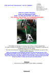
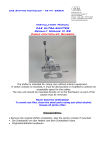
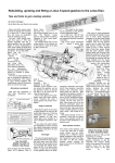
CAE Shifting Technology 45141 ESSEN Christian Au Leimkugelstrasse 3 45141 Essen Phone +49 201 8777 802 e-mail: [email protected] www.cae-racing.de Installation Manual CAE ULTRA-SHIFTER MINI R53 und R56 Fitting with stock shiftcables If center console is mounted, it must be dismounted or modified to achieve an acceptable space for the cables. The new unit should be mounted directly on to the floorboard, so part of the carpet must be removed. GENERAL INFORMATION Before the assembly of the Balljoints lubricate the seat with good grease. After completing the shifter, secure the Ballstud with a cotter pin. All screws and nuts on the shifter must have Lock-Tite or anything that keeps the screws or nuts from coming loose. Never bend the controller cables! To avoid rust film, clean the steel parts with oil ever so often. To clean the Alu-parts use ethyl alcohol Remount Loose the Shift boot including frame from the center console Lift the Car with an approved lifting device safely. Let hang the exhaust at rearside, its not required to reinstall him then remove Dismount the underbody heat panels to get access to the shiftbox if you have to change the cables required at R53 pre facelift) do it now remove the plastic cover from the shiftbox pull the cable pans from the levers and pull the cable clamps out of the housing unscrew the shiftbox (Torx 30) and take it out to downside, also the shiftboot reinstall the center console, if you like to use it later you have to cut out it as necessary Installation : pull of the coupling rod and unscrew the lower ball joint, otherwise it will disturb at introduction of the unit through the body hole Put on sealant under the body sheet: Introduce the shifter from downside into the tunnel and screw it with delivered M6x16, stop rings and washers. While this put the cables into the shiftbox already seeure cable with clamps as shown note the cutted edge of delivered clamp 2 Push the Ball pans on the cables Mount the cover sheet also with sealant Setting the shift range 6 speed Gearbox Coupling rod is not mounted Adjust central position of the lever by setting the spring stop under the shift lever bracket with 5mm Allen. The shift lever should be in the (neutral) level 3./4.Gang about 5 degrees tilted away from the driver. Select 3.or 4th Gear by moving lever for- or backwards Select 3.or 4th Gear by moving lever for- or backwards NOW INSTALL THE COUPLING ROD : Adjust it for fitting to the ball joints (Pan with the ring is LEFT THREAD !!) Control: 3rd / 4th Gear can be switched easy and at selected gear the lever has the same play to right and left If unbalanced readjust until its ok fix the Ball socket by cotter pin and lock the M6 nuts at the coupling rod. 3 Shift gearbox by the gearlever in level 1/2 (search) and tune the adjustment screw until the gears can be changed well. Do it also in level 5/6 Pull the reverse mechanism at the Lever and select reverse gear. Screw in stop screw until the reverse gear goes in clean If the lower part of the lever collide with the right cable you should adjust the central position of the shift lever slightly more to the right, and start with step 1. After installation, check all the essential functions of the Shifter while driving and adjust if necessary. Wrong adjustment will destroy your gearbox Remove the heat shields, exhaust check for proper function If center console should be mounted cut out as necassary CAE Shifting Technology wishes you a good trip If you experience any problems or questions, please contact us absolutely, we need YOUR feedback to improve our products 4