1
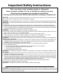
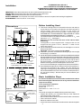
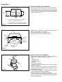
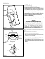
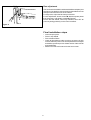
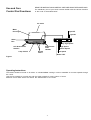
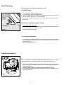
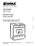
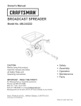
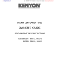
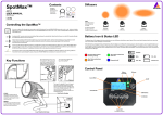
SIROCCO VENTILATION HOOD OWNER’S GUIDE READ AND SAVE THESE INSTRUCTIONS Models: B81200 Series Important Safety Instructions Take care when using cleaning agents or detergents. Select products suitable for use in household cooking area only. Certain locales require make-up air calculations for total airflow. Consult your local codes and an HVAC professional before installing or using this hood. CAUTION - To reduce risk of fire and to properly exhaust air, be sure to duct air outside – Do not vent exhaust air into spaces within walls or ceilings or into attics, crawl spaces, or garages. CAUTION - For General Ventilating Use Only. Do Not Use To Exhaust Hazardous Or Explosive Materials And Vapors. WARNING – TO REDUCE THE RISK OF FIRE, ELECTRIC SHOCK, OR INJURY TO PERSONS, OBSERVE THE FOLLOWING: a. Use this unit only in the manner intended by the manufacturer. If you have questions, contact the manufacturer. b. Before servicing or cleaning unit, switch power off at service panel and lock the service disconnecting means to prevent power from being switched on accidentally. When the service disconnecting means cannot be locked, securely fasten a prominent warning device, such as a tag, to the service panel. WARNING – TO REDUCE THE RISK OF A RANGE TOP GREASE FIRE: a. Never leave surface units unattended at high settings. Boilovers cause smoking and greasy spillovers that may ignite. Heat oils slowly on low or medium settings. b. Always turn hood ON when cooking at high heat or when cooking flaming foods. c. Clean ventilating fans frequently. Grease should not be allowed to accumulate on fan or filter. d. Use proper pan size. Always use cookware appropriate for the size of the surface element. WARNING – TO REDUCE THE RISK OF INJURY TO PERSONS IN THE EVENT OF A RANGE TOP GREASE FIRE, OBSERVE THE FOLLOWING: a. SMOTHER FLAMES with a close-fitting lid, cookie sheet, or metal tray, then turn off the burner. BE CAREFUL TO PREVENT BURNS. If the flames do not go out immediately, EVACUATE AND CALL THE FIRE DEPARTMENT. b. NEVER PICK UP A FLAMING PAN – You may be burned. c. DO NOT USE WATER, including wet dishcloths or towels – a violent steam explosion will result. d. Use an extinguisher ONLY if: 1. You know you have a Class ABC extinguisher, and you already know how to operate it. 2. The fire is small and contained in the area where it started. 3. The fire department is being called. 4. You can fight the fire with your back to an exit. WARNING – TO REDUCE THE RISK OF FIRE, ELECTRIC SHOCK, OR INJURY TO PERSONS, OBSERVE THE FOLLOWING: a) Installation work and electrical wiring must be done by qualified person(s) in accordance with all applicable codes and standards, including fire-rated construction. b) Sufficient air is needed for proper combustion and exhausting of gases through the flue (chimney) of fuel burning equipment to prevent back drafting. Follow the heating equipment manufacturer’s guideline and safety standards such as those published by the National Fire Protection Association (NFPA), and the American Society for Heating, Refrigeration and Air Conditioning Engineers (ASHRAE), and the local code authorities. c) When cutting or drilling into wall or ceiling, do not damage electrical wiring and other hidden utilities. d) Ducted fans must always be vented to the outdoors. WARNING - TO REDUCE THE RISK OF FIRE, USE ONLY METAL DUCTWORK. WARNING - Electrical Shock Hazard - Can result in serious injury or death. Disconnect appliance from electric power before servicing. If equipped, the fluorescent light bulb contains small amounts of mercury which must be recycled or disposed of according to Local, State, and Federal Codes. FOR RESIDENTIAL USE ONLY NOT TO BE INSTALLED OVER GAS GRILLS PLEASE READ ENTIRE INSTRUCTIONS BEFORE PROCEEDING. INSTALLATION MUST COMPLY WITH ALL LOCAL CODES. Installation IMPORTANT: Save these Instructions for the Local Electrical Inspector’s use. INSTALLER: Please leave these Instructions with this unit for the owner. OWNER: Please retain these instructions for future reference. SAFETY WARNING: Turn off power circuit at the service entrance and lock out panel, before wiring this appliance. REQUIREMENT: 120 V AC, 60 Hz. 15 or 20 Amp Before Installing Hood Dimensions Cabinet Front View 15 9/16" Fixing Point 1 Fixing Point 1 Fixing Point 2 Fixing Point 2 24” - 30” - 36” Cabinet Top View Internal Width 22 1/16" (24" Model)** 28 7/16" (30" Model)** 34 7/16" (36" Model)** 1 3/4" Rearside of the Cabinet/Hood 2 13/16" max 13 3/16" * min 10 13/16" * Cut-Out for 5" Duct C L Cut-Out for 1/2" Conduit 3 7/16" Cabinet Door * Do not consider the door of the cabinet ** Use spacers for 1/4" wider cabinet Cabinet Right/Left Side View min Depth of Recessed Area = 7 1/2" Cabinet Door Fixing Point 1 min Height of Recessed Area = 15 3/16" 6" Fixing Point 2 5 1/16" 13/16" 3 3/8" 11/16" 4 1/16" 10 13/16" 17 11/16" Figure 1 Pin Housing Spacer Pin Spacer for 1/4 wider cabinet Figure 2 Motor Housing Fixing Points 1-2 Snap Spacer Pins Into Their Housings 1. This hood is designed to be mounted flush to the rear wall (to avoid clearance from wall to hood) and to the internal sides of cabinet (where hood must be fixed); for this reason we suggest installing this hood only inside a cabinet having an internalwidthof221/16”forthe24”Model, 287/16”forthe30”Model,347/16”forthe 36”Modelandwithaninternaldepthofminimum71/2”.Seefigure1. The external depth of the cabinet must be minimum 10 13/ 16 ” and maximum 13 3 / 16”. See figure 1. Attention! Do not consider the door of the cabinet when measuring. The appliance is also supplied with 4 spacers that can be snapped at fixing point 1 and 2 , cabinets 1 / 4 ” wider can be used, see figure 2. 2. For the most efficient air flow exhaust, use a straight run or as few elbows as possible. CAUTION: Vent unit to outside of building ONLY. 3. If allowed in your area, use metallic flex ducting only to connect rigid duct directly to transitions. 4. COLD WEATHER installations should have an additional backdraft damper installed to minimize backward cold air flow and a nonmetallic thermal break to minimize conduction of outside temperatures as part of the ductwork. The damper should be on the cold air side of the thermal break. The break should be as close as possible to where the ducting enters the heated portion of the house. A non-return smoke damper is supplied mounted on the transition. 5. Hood installation height above cooktop is at the users preference. The lower the hood above the cooktop, the more efficient the capturing of cooking odors, grease and smoke. We recommend that the hood be installed 18” to 36” over an electric cooktop and 25” to 36” over a gas cooktop . Be sure that your hood model fits your installation. Basic Installation Steps For easiest installation, the hood should be installed in the cabinet before mounting the cabinet to the wall. In any case the installation steps do not change. Tools required for installation Screw driver (philips # 1 ) Electric drill with twist bit 5/64” and 7/32” or 15/64” Tape This Hood can easily be installed following these basic steps: • Prepare the cabinet (cut out bottom and top of the cabinet as required and mark fixing points) • Run conduit and duct sections to the hood and make connections • Fix the hood to the cabinet • Mount the cabinet on the wall • Connect duct to the outside and conduit section to the service panel 3 Installation Prepare the cabinet for installation 22 1/16" (24" Model)** 28 7/16" (30" Model)** 34 7/16" (36" Model)** • Mark and cut-out the cabinet bottom as shown in figure 3. • Fit the template, which comes with the hood, on the inner right side of the cabinet making sure the side with arrows matches with the lower edge of the cabinet and the rear edge of the cabinet or cut-out. Rearside of the Cabinet*** max 13 3/16" * min 10 13/16" * 7 1/2" CUT-OUT C L Cabinet Door * Do not consider the Door of the Cabinet ** Add 4/16" when using Spacers Figure 3 *** Rearside of the Cut-Out for cabinet deeper than 13 3/16" (without considering the door) • Drill 2 holes 5/64” (see figure 4 - fixing point 1 and 2) and 1 blind hole 15/64” in diameter, 13/64” in depth. • Move template to the other side and repeat. • Make cut-out for duct and conduit, see figure 1. Cabinet Door Fixing point 1-2 Fixing point 1-2 Template cutout for 1/2" Conduit and 5" Duct Template Bottom of the cabinet Backside border Backside of the cabinet Blind hole (Side Springs Housing) Figure 4 Prepare the hood for installation • Remove the hood from packaging, check its condition and make sure the following pieces are included: 1 hood, 1 registration card 1 instruction manual 1 template 1 transition with damper 1 plastic bag with 4 hood fixing screws + 1 transition fixing screw and 4 spacers. • Remove the light shield, unscrew and remove lamps to prevent damage when installing (see paragraph on “Light replacement” for details). • Pull out the slider and remove the grease filters (see paragraph “To remove the grease filters” for details). • Fit the transition on the outlet hole of the hood: This has a bayonet lock and must be fixed to the hood with one screw (Figure 5), check the opening and closing of the damper mounted inside. Figure 5 4 Installation Install the Hood • Set the motor housing into the opening. • Push the spring inside the motor housing using a screw driver as a lever from the inside of the motor housing. • Insert it completely in place taking care to snap sides springs into the blind holes made for temporary fixing and that conduit and duct section, if already fitted, run freely across the cutouts on top of the cabinet, see figure 6. • Fix the hood permanently with two screws (4.5x16) per side to be inserted frome the inside of the hood to the corresponding side fixing points 1 and 2 drilled on the cabinet, see figure 7. • Connect a 5” duct to the transition and seal with tape. • Connect to power supply Attention! While mounting the hood on the wall cabinet be sure once the hood has been fastened, that the wiring compartment is easily and safely accessible, in order to make safety inspections and/or maintenance operations. Cabinet Side Spring Figure 6 WARNING! ELECTRICAL GROUNDING INSTRUCTIONS THIS APPLIANCE IS FITTED WITH AN ELECTRICAL JUNCTION BOX WITH 3 WIRES, ONE OF WHICH (GREEN/YELLOW) SERVES TO GROUND THE APPLIANCE. TO PROTECT YOU AGAINST ELECTRIC SHOCK, THE GREEN/YELLOW WIRE MUST BE CONNECTED TO THE GROUNDING WIRE IN YOUR HOME ELECTRICAL SYSTEM, AND IT MUST UNDER NO CIRCUMSTANCES BE CUT OR REMOVED. Side Spring Warning: Turn off power circuit at the service panel before wiring this unit. 120 VAC, 15 or 20 Amp circuit required. Cabinet Door Fixing point 1-2 Fixing point 1-2 a. Remove j-box cover as shown in Figure 8. b. Remove the knockout and install the strain relief (conduit) connector (1/2") in junction box. c. Run 3 wires; black, white and green (#16 AWG) in 1/2" conduit from service panel to junction box. d. Connect black wire from service panel to black or red in junction box, white to white and green to green-yellow. See Figure 8. e. Close junction box cover. Template cutout for 1/2" Conduit and 5" Duct Template Bottom of the cabinet Backside border Backside of the cabinet Figure 7 Blind hole (Side Springs Housing) Conduit Figure 8 5 Box adjustment M The hood can be installed in cabinets with different depths (see also figure 1 for details); however the front of the slider box must always be flush with the front of the cabinet. For alignment, adjust the back stops of the box. For box adjustment, loosen screws M, slide the square plates P as necessary, and tighten screws M (Figure 8). Ensure that the drawer, when fully retracted, turns OFF all power by acting positively on the rear microswitch. P Figure 8 Final installation steps • • • • Insert lamps in place. Fit the Lamp Shield. Fit the Grease Filters. Check all light bulbs to make sure they are secure in their sockets, then turn power on in service panel and check lights and blower operation per Use & Care section of this manual and install filters. • Make sure to leave this manual for the home owner. 6 Use and Care Control Pad Functions READ THE INSTRUCTIONS CAREFULLY BEFORE USING THE RANGE HOOD. For satisfactory use of your hood, become familiar with the various functions of the hood as described below Air outlet Motor Housing Light OFF Light ON 0 1 2 3 4 Slider Box 0 1 Very High Speed Right Grease Filter Handles Left Grease Filter Handles Lamp Shield Grease Filters High Speed Medium Speed Low Speed Blower OFF Figure 7 Operating Instructions The blower should be turned on for about 5 minutes before cooking in order to establish air currents upward through the hood. Use the low speeds for normal use and the higher speeds for strong odors or fumes. Minimize cross drafts which will reduce the effectiveness of the hood. 7 Hood Cleaning Be sure lights are cool before cleaning the hood. To Clean Filters • The metal grease filters will last forever. They are made of anodized aluminum • It is recommended that the filters be washed at least once a month; they can be washed by hand or in the dishwasher. • Drain water through edge holes and let each filter dry thoroughly before replacing it. To Remove The Metal Grease Filters • Turn blower and lights off. • Push simultaneously the two grease filter handles first upwards, then pull towards the center and extract the filters Figure 8. • To reinstall, reverse procedure. Figure 8 To Clean Hood Surface • For general care, wipe the outside of the white or black hood with sudsy water or general kitchen household cleaners, rinse well and dry with clean soft cloth to avoid water marks. • Do not use abrasive products. Lights replacement R Q G NOTE: Turn blower and lights off. Make sure the lights are cool. If new lights do not operate be sure lights are inserted correctly before calling service. • Remove the light shield Q by pushing simultaneously the two unlocking buttons R (Figure 9); for safety reasons make sure to remove the light shield from its suspension slides G. Attention: When removing, handle the light shield by the glass. • Pull out fluorescent tube and replace with Philips Type PL-S 9 Watt maximum. • Refit the light shield. Figure 9 8 9 10 11 LI1QVB Ed. 05/02