1
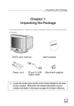
User’s Manual
Color Display Monitor
SAFETY SYMBOLS
This manual uses the safety symbols below. They denote critical information. Please
read them carefully.
WARNING
Failure to abide by the information in a WARNING may result in serious
injury and can be life threatening.
CAUTION
Failure to abide by the information in a CAUTION may result in moderate
injury and/or property or product damage.
Indicates a prohibited action.
Indicates to ground for safety.
Copyright© 2000 by EIZO NANAO CORPORATION. All rights reserved. No part of
this manual may be reproduced, stored in a retrieval system, or transmitted, in any form
or by any means, electronic, mechanical, or otherwise, without the prior written
permission of Eizo Nanao Corporation.
Eizo Nanao Corporation is under no obligation to hold any submitted material or
information confidential unless prior arrangements are made pursuant to Eizo Nanao
Corporation's receipt of said information. Although every effort has been made to
ensure that this manual provides up-to-date information, please note that EIZO monitor
specifications are subject to change without notice.
ENERGY STAR is a U.S. registered mark.
Apple and Macintosh are registered trademarks of Apple Computer, Inc.
VGA is a registered trademark of International Business Machines Corporation.
DPMS is a trademark and VESA is a registered trademark of Video Electronics
Standards Association.
Windows is a registered trademark of Microsoft Corporation.
ScreenManager, PowerManager, QuickSet and i·Sound are trademarks of
Eizo Nanao Corporation.
FlexScan, SuperErgoCoat and EIZO are registered trademarks of Eizo Nanao
Corporation.
As an ENERGY STAR® Partner, Eizo Nanao Corporation has determined
that this product meets the ENERGY STAR guidelines for energy efficiency.
2
CONTENTS
PRECAUTIONS ............................................................................. 4
1.
INTRODUCTION ............................................................................ 9
2.
ENGLISH
1-1. Features ....................................................................................................... 9
1-2. Package Contents ........................................................................................ 9
1-3. Controls & Connectors ................................................................................ 10
INSTALLATION ........................................................................... 11
2-1. Connecting the monitor to the PC ............................................................... 11
2-2. Getting Ready for Operation ....................................................................... 13
3.
SCREEN ADJUSTMENT ............................................................ 14
3-1. How to use the ScreenManager .................................................................. 14
3-2. Adjustments and Settings ........................................................................... 15
3-3. Special Function ......................................................................................... 22
4.
CONNECTING TWO PCs TO THE MONITOR .............................. 23
5.
MAKING USE OF USB (Universal Serial Bus) .......................... 24
6.
TROUBLESHOOTING ................................................................. 28
7.
CLEANING ................................................................................... 33
8.
SPECIFICATIONS ....................................................................... 34
9.
GLOSSARY.................................................................................. 38
10. INDEX .......................................................................................... 40
CONTENTS
3
PRECAUTIONS
IMPORTANT!
• This product has been adjusted specifically for use in the region to which it was
originally shipped. The performance of the product, (i.e. picture geometry, picture
positioning and color convergence and purity in the case of color monitors) is
optimally adjusted to the earth’s magnetic field of the specific destination. If operated
outside the region to which it was originally shipped, the product may not perform as
stated in the specifications.
• To ensure personal safety and proper maintenance. Please read this section and the
caution statements on the monitor (refer to the figure below).
[Location of the Caution Statements]
The equipment must be connected to a grounded main outlet.
Jordet stikkontakt skal benyttes når apparatet tilkobles datanett.
Apparaten skall anslutas till jordat nätuttag.
WARNING
• If the monitor begins to emit smoke, smells like something is
burning, or makes strange noises, disconnect all power connections
immediately and contact your dealer for advice.
Attempting to use a malfunctioning monitor can be dangerous.
• Do not dismantle the cabinet or modify the monitor.
Dismantling the cabinet or modifying the monitor may result in electric
shock or burn.
• Refer all servicing to qualified service personnel.
Do not attempt to service this product yourself as opening or removing
covers may expose you to dangerous voltage or other hazards.
4
PRECAUTIONS
WARNING
ENGLISH
• Keep small objects away from the monitor.
Small objects may accidentally fall through the ventilation slots into the
cabinet, leading to fire, shock, or equipment damage.
• Keep liquids away from the monitor.
Spillage into the cabinet may result in fire, electric shock, or equipment
damage. If an object or liquid falls/spills into the cabinet, unplug the
monitor immediately. Have the unit checked by a qualified service
engineer before using it again.
• Place the monitor on a strong, stable surface.
A unit placed on an inadequate surface may fall, resulting in injury or
equipment damage. If the monitor falls, disconnect the power immediately
and have the unit checked by a qualified service engineer before using it
again. Using a monitor after it has been dropped may result in fire or
electric shock.
OK
• Set the monitor in an appropriate location.
* Do not install in a dusty or humid environment.
* Do not place in a location where steam can have direct contact with the
screen.
* Do not place near heat generating devices or a humidifier.
• Keep the plastic packing bags away from children and infants.
Plastic bags can be dangerous. To avoid danger of suffocation, keep the
bag away from babies and children.
• Keep power terminal covers for the optional i·Sound™ sound unit
away from children and infants.
Children and infants may accidentally swallow the covers and choke. If
swallowed, consult a doctor immediately.
PRECAUTIONS
5
WARNING
• Use the enclosed power cord. If using the power cord other than the
enclosed one, use the following cord.
[USA and Canada]
Use a UL LISTED/CSA LABELED or CERTIFIED power cord set meeting
the following specifications.
* Rating:
min. 125 V, 10 A
* Length:
max. 2.0 m
* Plug type:
NEMA 5-15P, Parallel blade, Grounding type, 125 V, 10 A
* Type:
SVT
[Europe]
Use a proper European standard approved power cord meeting the
following specifications.
* Rating:
min. 250 V, 10 A
* Length:
max. 2.0 m
* Type:
H05VV-F 3G 1 mm2
Use a plug type approved by the country where you reside. Failure to do so
may cause fire or electric shock.
• To disconnect the power cord, grasp the plug firmly and pull.
Never tug on the cord, doing so may cause damage and could result in fire
or electric shock
• The equipment must be connected to a grounded main outlet.
• Use the correct voltage.
* The monitor is designed for use with a specific voltage only. Connection
to a different voltage may cause fire, electric shock, or other damage.
* Do not overload your power circuit, as this may result in fire or electric
shock.
* For proper connections of the power cord, be certain to plug the power
cord to the provided monitor connector and directly to a wall outlet. By
not doing so may result in fire or electric shock.
• Handle the power cord with care.
* Do not place the cord underneath the monitor or other heavy objects.
* Do not pull on the cord.
* Do not attempt to repair a damaged cord.
If the power cord becomes damaged, stop using it. Use of a damaged cord
may result in fire or electric shock.
• Never touch the plug and power cord if it begins to thunder.
If it begins to thunder, do not touch the plug, power cord or cable.
Touching them may result in electric shock.
6
PRECAUTIONS
OK
CAUTION
ENGLISH
• Handle with care when carrying the monitor.
* Disconnect the power cord, signal cables and remove the optional
i·Sound™ sound unit (if applicable). Moving the monitor with the cord
attached or lifting it by the i·Sound™ sound unit is dangerous. It may
result in injury or equipment damage.
* Note that the monitor is heavier at the front than at the rear. Do not
move it alone. Always work with another person.
* The screen is optically coated to reduce glare. Keep hard objects (such
as buttons, tiepins, and other clothing accessories) away from the screen
surface to prevent scratches.
OK
• Do not block the ventilation slots on the cabinet.
* Do not place books or any other papers on the ventilation slots.
* Do not install the monitor in a closed space.
* Do not use the monitor laying down or upside down.
* Do not remove the tilt-swivel stand.
Using the monitor in this way block the ventilation slots and prevents
proper airflow, leading to fire or other damage.
• Do not sit on the cabinet or place any heavy objects on the cabinet.
A unit with heavy objects on it may fall or be damaged and result in injury.
• When adjusting the viewing angle of the monitor, do not do so by
handling i·Sound™ sound unit (if applicable).
Adjusting the monitor in this way may break the unit or cause bodily
injury.
• At the end of the day or if you plan to leave the monitor unused for an
extended period, after turning off the power switch disconnect the
power cord from the wall socket so that no power connections are
made.
PRECAUTIONS
7
CAUTION
• Do not touch the plug with wet hands.
Touching the plug with wet hands is dangerous and can cause electrical
shock.
• Use an easily accessible power outlet.
This will ensure that you can disconnect the power quickly in case of a
problem.
• Unplug the monitor before cleaning it.
Cleaning the monitor while it is plugged into a power outlet may result in
electric shock.
• Never use thinner, benzene, alcohol (ethanol, methanol, or isopropyl
alcohol), abrasive cleaners, or other strong solvents, as these may
cause damage to the cabinet or CRT.
• Periodically clean the area around the plug.
Buildup of dust, water, or oil on the plug may result in fire.
8
PRECAUTIONS
1. INTRODUCTION
Thank you very much for choosing an EIZO Color Display Monitor.
1-1. Features
ENGLISH
• Fully flat screen CRT.
• T761 Horizontal scanning frequency of 30-115 kHz
Vertical scanning frequency of 50-160 Hz
T962 Horizontal scanning frequency of 30-130 kHz
Vertical scanning frequency of 50-160 Hz
• Fine contrast function with a wider margin provides for a more brightly contrasted
picture.
• Dual inputs with individual color configuration.
• USB (Universal Serial Bus) hub supported.
1-2. Package Contents
Please contact your local dealer for assistance if any of the listed items are missing or
damaged.
• Monitor
• Signal Cable
(MD-C87/MD-C100)
• Power Cord
• EIZO CRT Utility Disk
• User’s Manual
• Quick Reference
• Warranty Registration Card
• Please retain the packing materials for future transference.
1. INTRODUCTION
9
1-3. Controls & Connectors
Front
(1) ScreenManager™
(2) USB Port with a drop down access lid
Downstream port x 1
(3) BNC/D-SUB Selection Button
(4) AUTO-SIZING Button
(5) Power Terminal Covers for the Optional
i·Sound Sound Unit. (Bottom side)
(6) QuickSet™ Control Pad
(Hereinafter “Control Pad”)
(7) Power Indicator
(1)
(2) (3)
(8)
Indicated color Power-on status
Green
Power is on (Normal mode)
Flashing Green Power save mode 1
Advance notice of monitor’s
off timer (See page 20)
Yellow
Power save mode 2
Flashing Yellow Power save mode with
monitor’s off timer
(See page 20)
(4) (5) (6) (7)
(8) Power Switch
Rear
(9)
(10)
(11)
(12)
(14)
(9) (10) (11) (13)
(12)
10
1. INTRODUCTION
Power Connector
D-Sub Mini 15 Pin Input Connector
BNC Input Connector
Termination Switch
Allows multiple monitors to be chained
together (Default termination is 75 Ω)
(13) Maintenance Port
(14) USB Port
Downstream port x 3
Upstream port x 1
2. INSTALLATION
2-1. Connecting the monitor to the PC
1.
Plug the signal cable into the connector at the rear of the monitor and
the other end of the cable into the video connector on the PC.
After connecting, secure the connection with the screw-in fasteners.
• Standard graphics board
Video Output Connector
D-Sub mini 15 pin
Standard graphics board
Signal Cable (Enclosed)
• Macintosh
Video Output Connector
D-Sub mini 15 pin
Macintosh (Blue & White)
Signal Cable (Enclosed)
Video Output Connector
D-Sub 15 pin
Macintosh
Macintosh Adapter (Optional)
Please consult EIZO dealer.
2. INSTALLATION
11
ENGLISH
• Be sure that the power switches of both of the PC and the monitor are OFF.
2.
Plug the power cord into the power connector at the rear of the
monitor. Then plug the other end of the cord into a power outlet.
WARNING
• The equipment must be connected to a grounded main
outlet.
• Use the enclosed power cord. If using the power cord
other than the enclosed one, use the following cord.
[USA and Canada]
Use a UL LISTED/CSA LABELED or CERTIFIED power cord
set meeting the following specifications:
* Rating:
min. 125 V, 10 A
* Length:
max.2.0 m
* Type:
SVT
* Plug type: NEMA 5-15P, Parallel blade,
Grounding type, 125 V, 10 A
[Europe]
Use a proper European standard approved power cord
meeting the following specifications:
* Rating:
min. 250 V, 10 A
* Length:
max. 2.0 m
* Type:
H05VV-F 3G 1 mm2
Use a plug type approved by the country where you reside.
Failure to do so may cause fire or electric shock.
3.
Turn on the monitor first, then the PC.
The monitor’s power indicator will light up (green). The monitor will warm up
briefly, then display an image. Whenever finishing your operation, turn off the PC
and the monitor.
(If an image does not appear, make sure that all connections have been made
properly. Refer to the “TROUBLE SHOOTING” (See page 28) for additional
advice.)
• Generally, for maximum viewing comfort, position the
monitor slightly below eye level. Staring at the monitor for
prolonged periods can cause eye strain. Be sure to take
adequate rests.
(A 10-minute rest period each hour is suggested.)
12
2. INSTALLATION
2-2. Getting Ready for Operation
Try each setting procedure if necessary in the following cases.
ENGLISH
The display image size and / or position is incorrect
Press the AUTO-SIZING button on the front panel. The
AUTO-SIZING function centers the displayed image,
aligning the image’s borders with respect to the monitor
frame. In general, press the AUTO-SIZING button
whenever changing the graphics board or the resolution
p.39)
, or when image size and/or position is incorrect. If
further adjustment is required, adjust the picture size/
position as desired using the ScreenManager (See page
14).
• A solid-color screen (i.e. red, green, blue) may appear briefly after pressing the
AUTO-SIZING button. This is not a malfunction.
• When the timing of the computer is same as the
preset timing or has been recognized before, the
following message will appear and remain on the
screen for 5 seconds. While the message is on the
screen, press the AUTO-SIZING button again to
automatically adjust the screen position. If not
wishing to adjust the screen, do not press the button
again or press the control pad. The message will
disappear.
The display area is too large or too small
Readjust the preferred refresh rates in accordance with the following look-up-table. Refer
to the PC or graphics board manuals on how to change the refresh rates.
[The maximum (non-interlaced) vertical refresh rates for these models]
Maximum Vertical Refresh rate (Hz)
640x480
800x600
T761
160
160
1024x768 1280x1024 1600x1200 1600x1280 1920x1440 2048x1536
142
107
92
86
76
-
T962
160
160
160
121
104
97
86
80
Using the monitor with Windows® 95/98/2000
A monitor information file is contained in the EIZO CRT Utility Disk included with the
monitor. It includes all the required information for best operation with Windows 95/98/
2000. Please install the enclosed utility and select your model name from the monitor
list in Windows 95/98/2000. For installation procedure, please read the readme.txt file
in the utility disk.
2. INSTALLATION
13
3. SCREEN ADJUSTMENT
• Allow the monitor to stabilize for at least 30 minutes before making image
adjustments.
3-1. How to use the ScreenManager
Up
Use the control pad on the front panel. The control pad can
be pressed in 5 directions, “Enter”, “Up”, “Down”, “Left”
and “Right”.
Left
Enter
Right
Down
1.
Entering the ScreenManager
Display the ScreenManager “Main menu” by pressing the “Enter” of the control
pad. Main menu displays the current connector type and frequency of the input
signal.
Main menu
Æ
2.
Making Adjustments and Settings
(1)
(2)
(3)
(4)
3.
Select the desired icon by using “Up”, “Down”, “Left” and “Right” keys.
Press the “Enter” key to display each adjustment/setting menu or “Sub menu”.
Make the required adjustments/settings by using the control pad.
To save the adjustments/settings and return to the Main menu, press the
“Enter” key.
Exiting the ScreenManager
To exit the ScreenManager, select the
“Exit from the “Main menu” and press
the Enter key. Pushing the down arrow key twice goes to the
“Exit” position
instantly.
• Leaving the ScreenManager idle for 45 seconds or more will turn the adjustment off
automatically without saving.
14
3. SCREEN ADJUSTMENT
3-2. Adjustments and Settings
Main menu
Sub menu
Adjustments and Settings
See page
—
Screen contrast and brightness*
—
Size
—
Screen size
—
Position
—
Screen position
—
Screen
Side Pin.
Side pin balance
—
Trapezoidal
Distortion
—
Tilt
Inclination
Uniformity
Convergence
Uniformity
Color
p. 16
p.38)
p.38)
—
—
Fine Contrast
To brighten the photo, picture image or
movie.
p. 17
Signal Filter 1
To decrease the slightly shadowed
images or characters.
p. 17
Signal Filter 2
To decrease the vertical bars.
p. 17
“Standard”
Color Temperature To set the color temperature p.38).
p. 18
Color Correction
To eliminate disparities in color
temperature and brightness due to an
irregular video signal output.
p. 18
To adjust each color,
(Red, Green and Blue).
p. 19
“Custom”
Others
—
p.39)
Convergence
Moiré Reduction Moiré
ENGLISH
Contrast
PowerManager To set the power save.
(With PC’s power saving system)
p. 20
Off Timer
To set the power save.
(With Monitor’s Off timer)
p. 20
Degauss
To degauss P.38).
p. 21
Button Setting
To customize the button function.
p. 21
Beep
To set beeper on/off.
p. 21
Menu Position
To adjust the menu position of
the ScreenManager.
p. 21
Language
To select the preferred language to use. p. 22
Input Priority
To select the priority input signal.
p. 23
Reset
To return to the factory default setting.
p. 22
* When a black background (e.g. DOS text) is used, setting the brightness at its
maximum is recommended because a dark setting will result in eye strain due to high
character contrast.
3. SCREEN ADJUSTMENT
15
< Screen >
• To adjust the uniformity
Reduce color uniformity errors at the edges of the screen caused by interference from
the geomagnetic field.
<T761>
< Uniformity >
Adjust the uniformity as desired by using the control pad.
<T962>
< Uniformity >
< Standard>
Select the direction the monitor is facing.
Select from the N, NE, E, SE, S, SW, W, NW and
Center (no correction). The “point” may be different
depending on the environment. Select the “Point” that
the maximal brightness and whiteness is uniformed.
* If the uniformity is corrected, continue on to (4).
* If some color patches remain in the corners after the
adjustment, continue on to (2).
(2)
< Top/Bottom >
Adjust the top/bottom uniformity.
(1)
Top
Bottom
(3)
< Top corner >
< Bottom corner >
Adjust the uniformity of the for 4 edges of the screen.
* Be sure to adjust the “Top corner” first, then adjust
the “Bottom corner”.
Top corner:
Control pad “left/right”...... Left upper
Control pad “up/down”..... Right upper
Bottom corner: Control pad “left/right”....... Left lower
Control pad “up/down”..... Right lower
16
3. SCREEN ADJUSTMENT
(4)
< Save >
Select “Save” and the press the enter button.
(If the settings are not saved, all adjustments will be
lost.)
*
<Reset>
Resets the uniformity function to the factory default
setting.
• To brighten the photo, picture image or movie
• To decrease a slightly shadowed image or characters
This function can decrease images or characters with slight shadows on the right side
when the characteristics of the graphics board do not match those of the monitor.
< Signal Filter 1 >
Select from mode 1 or 2 in the Signal Filter 1 menu,
whichever displays the image better.
• To decrease the vertical bars
This function can decrease vertical bars and brightness lines on the right side of
images or characters.
<Signal Filter 2>
Adjust the percentage by using the control pad until the
images seem clear in the Signal Filter 2 menu.
3. SCREEN ADJUSTMENT
17
ENGLISH
< Fine Contrast >
Select “Text”, “Picture” or “Movie” for preferred mode as
desired by using the control pad.
* Available to adjust the preferred “contrast and
brightness” after setting.
* Select “Movie” when the entire screen is dark.
* Select “Text Mode” to display the text on word
processor or calculating software.
* The AUTO-SIZING button can be customized to
activate this function easily.
(Textà Pictureà Movieà Text...) (See page 21).
< Color >
• To set the color temperature
Temperature can be set from 4,000 K to 10,000 K, in 500 K increments.
(Including the 9,300 K default setting.)
< Temperature>
Set the preferred “Color temperature”.
“Standard” mode
• To eliminate disparities in color temperature and brightness due
to an irregular video signal output
Color Correction corrects irregular video signal output levels to eliminate disparities
in color temperature and brightness.
When two PCs are connected to one monitor or to several monitors and this function is
utilized, all monitors will display nearly uniform color temperature and brightness.
(1) Open a www browser and the Pattern.html in the EIZO
CRT utility disk. If this file is not available, open a
window on the Windows or Macintosh OS for
alternative use. Refer to the picture on the left.
(2)
“Standard” mode
White window
pattern with a
size that is
more than 1/5
and less than
1/2 of the
whole display
area.
Set the background to black
BN C /A UTO
D- SUB
< Color Correction >
Select “OK”.
All other adjustments are off during the correction.
(The operation takes about 20 to 30 seconds. Do not
change the “Pattern” during the correction.)
When color correction is complete, the result is
displayed.
• Successful
• Unsuccessful
When unsuccessful, no adjustment to the screen is made.
Press any button on the front panel to turn this message
menu off and return to the sub menu.
18
3. SCREEN ADJUSTMENT
• To adjust each color , (Red, Green and Blue)
Adjust the “Cutoff”p.38) and “Gain”p.38) for color tone.
(1) First, set the monitor to maximum contrast and
brightness.
(2)
“Custom” mode
< Temperature>
Set the color temperature that is close to the desired
color.
(3)
< Cut off >
Adjust each color to become a uniform black level by
using the “Cutoff” function.
(4)
< Gain >
Adjust each color to the desired white level by using
the “Gain” function.
(5)
< Save >
Select “Save” and then press the Enter key.
The adjustment data will be lost, if the monitor is
turned off without saving changes.
* The values shown in percentages (%) for both the
Cutoff and Gain are available only as a reference tool.
3. SCREEN ADJUSTMENT
19
ENGLISH
* In the following cases, color correction will be
unsuccessful.
• When the input signal level is lower than 0.5 Vp-p
or higher than 1.0 Vp-p.
• When window size is not appropriate.
• When the termination switch on the rear of the
monitor is set to“∞” and connecting the monitor
with a BNC cable.
* Color correction automatically corrects color
temperature from 4000 K to 10000 K at 1 time.
Therefore, proper color displays in the every color
temperature after correction.
* Every time the PC (graphics board) and input signal
change, execute color correction.
< Others >
• To set the power save
There are two power save settings choose the setting which matches your
environment.
• Do your part to conserve energy, turn off the monitor when you are finished using it.
Complete energy use can only be accomplished by disconnecting the monitor’s
power supply cord from the plug receptacle.
1. With PC’s power saving system (VESA DPMS p.39))
The monitor detects the signal from the PC and executes the power saving
accordingly, as shown in the table below.
< PowerManager >
Select “On”.
Operate the mouse or keyboard to return to a normal
screen.
[Power saving system]
PC Signal
ON
Screen
Operation
LED
Green
STAND-BY
SUSPEND
OFF
Blank screen
Green
Power save (Mode 1) Flashing green
Power save (Mode 2) Yellow
Power consumption
T761 130 W (normal)
T962 160 W (normal)
80% of normal
Less than 10 W
Less than 3 W
2. With Monitor’s off timer system
Without the PC’s power saving system, the off timer allows the monitor to Enter a
power save mode after a predetermined amount of time has lapsed.
< Off Timer >
Select “Enable” and press the left/right keys on the control
pad to set the “On period”. (1 to 23 hours)
Press any direction of the control pad or to turn the power
off then on again to return to a normal screen.
[Power saving system]
Time
On period (1-23)
Power consumption
T761 130 W (normal)
T962 160 W (normal)
Last 15 min. in
T761 130 W (normal)
“On period”
Advance notice*
Flashing green
T962 160 W (normal)
“On period” expired Power save mode
Flashing yellow Less than 3 W
* To delay entering the power save mode, press any direction of the control pad
during the advance notice mode.
20
Screen
Operation
3. SCREEN ADJUSTMENT
LED
Green
• To degauss the monitor
• To customize the button function (Auto sizing or Fine Contrast)
< Button Setting >
Select “Auto Sizing”(Auto sizing function <See page 13>)
or “Fine Contrast” (Brighten the photo, picture image or
movie <See page 17>).
• To set beeper on/off
< Beep >
Select the beep “On" or "Off"
Short beep
• ScreenManager item selected.
• ScreenManager parameter adjusted to minimum or
maximum limit.
• BNC/D-Sub selection button pressed.
Long beep
• AUTO-SIZING button pressed.
• ScreenManager data-save executed.
• When the “Color Correction” function of the color
adjustment is successfully executed.
Four short beeps
• The signal cable of the PC is not properly connected to the
monitor.
• Monitor received unsupported signal frequency.
• When the “Color Correction” function of the color
adjustment is unsuccessfully executed.
Every fifteen seconds • The last 15 min. in “On period”.
• To adjust the menu position of the ScreenManager
< Menu Position >
Adjust the menu position as desired by using the control
pad.
3. SCREEN ADJUSTMENT
21
ENGLISH
< Degauss >
Press the center of the control pad.
* The degauss circuitry takes about 30 minutes to regain
maximum power following degaussing.
• To select the preferred language to use
< Language >
Six languages are available to choose from:
English, German, French, Spanish, Italian and Swedish.
The ScreenManager’s messages will appear in the selected
language.
• To return to the factory default setting
< Reset >
Select “Reset”.
* “ Uniformity” in the “Screen” menu dose not return to
the factory default setting (See page 16).
Default settings are as follows.
Contrast
Fine Contrast
Signal Filter 2
PowerManager
Button Setting
Language
100% / 50%
Text Mode
100%
On
Auto Sizing
English
Moiré Reduction
Signal Filter 1
Color
Off Timer
Beep
Input priority
0%
Mode 1
Standard /9,300K
Disable
On
Auto (D-SUB)
3-3. Special Function
Shortcut Keys
The brightness and contrast can be adjusted by pressing the “Up”, “Down”, “Left” and
“Right” keys of the control pad directly. Press the “Enter” of the control pad to save and
exit the settings after the adjustment.
Adjustment Lock
Use the “Adjustment Lock” function, to prevent any accidental changes.
Locked function
Unlocked function
• Adjustments and settings in the ScreenManager.
• AUTO-SIZING button.
• Adjustment of contrast and brightness by the shortcut keys.
• BNC/D-Sub Selection button.
• To lock
Press on the AUTO-SIZING button while switching on the monitor’s power.
• To unlock
Switch off the monitor’s power, then hold down the AUTO-SIZING button once
again and turn the power back on.
22
3. SCREEN ADJUSTMENT
4. CONNECTING TWO PCs TO
THE MONITOR
Two PCs can be connected to the monitor through the BNC/D-Sub input connections on
the back of the monitor.
(Example)
Apple Macintosh
(Blue & White)
ENGLISH
à
Standard graphics board
MD-C53A (Optional)
Selecting the active input
The BNC/D-Sub selection button on the front panel can be
used to select either the BNC or D-Sub connection as the active
input. Every time the button is pressed, the input changes.
The priority input signal
This function is used to select which PC will have priority to control the monitor when
utilizing two PCs. In the following cases, the signal given preference will be displayed
automatically.
• When the monitor is turned on.
• Once a priority is selected in the “Input Priority” function, whenever a change of
signal is detected at the selected input, the monitor will switch the input to that signal.
< Input Priority>
< Others > menu /
Select “Auto” with the left/right arrow keys and select the
desired input signal mode.
* “Auto”:
If only one PC is connected to the monitor,
it automatically detects and displays the
signal from that PC.
* “Manual”: Select the active input by pressing the
BNC/D-SUB selection button.
Adjustment data can be saved for both PCs
The following adjustment and setting data can be saved for each input signal
(BNC/D-Sub).
Contrast/Brightness
Fine Contrast
Signal Filter 1
Signal Filter 2
Color Mode “Standard” Temperature
Color Mode “Standard” Color Correction
Color Mode “Custom”
p.15
p.17
p.17
p.17
p.18
p.18
p.19
4. CONNECTING TWO PCs TO THE MONITOR
23
5. MAKING USE OF USB
(Universal Serial Bus)
This monitor provides a hub which supports the USB standard. When connecting to a
USB compliant PC or another hub, the monitor functions as a hub to which the USB
compliant peripherals can be easily connected.
As an added advantage, the monitor can be controlled from a PC with a mouse or
keyboard when utilizing the enclosed utility software “ScreenManager Pro for USB”
(Windows 98/2000).
Required system environment
• PC equipped with USB ports or another USB hub connected to the USB compliant PC
• Windows 98/2000 // Mac OS 8.5.1 or later
• USB cable (Sold separately)
• The USB hub function may not work properly depending on the PC, OS or
peripherals. Please consult the manufacturer of each device about the USB support.
• When the monitor is not on, the peripherals connected to the downstream ports will
not operate.
• Even if the monitor is in a power saving mode, the devices connected to the
monitor’s USB ports (both the upstream and the downstream) will function.
Connecting to the USB HUB (Setting up the USB function)
• Do not connect the downstream port of the monitor to any peripherals until finishing
the USB function.
• The followings are procedures for the Windows 98 Second Edition/2000 and Mac OS.
1.
Connect the monitor to the PC with the signal cable (See page 11) first, then turn on
the PC.
2.
Connect the upstream port of the monitor to the downstream port of the USB
compliant PC or another hub by using the USB cable .
USB CABLE
Upstream port:
Connect the USB
compliant PC or another
hub using the USB cable.
After connecting the USB cable, the USB function can be set up automatically.
24
5. MAKING USE OF USB (Universal Serial Bus)
• Please follow the instructions below for proper installation.
[For Windows 2000]
1. Click the “Start” button and open the “Control Panel” from “Settings”.
2. Select “System” from the “Control Panel” to open the “System Properties”.
3. Select “Device Manager” from “Hardware” in the “System Properties” and confirm
that the following icon is found.
- “EIZO HID Monitor Controls” appears under “Human Interface Devices”.
[For Mac OS ]
1. Select the “Apple System Profiler” from the Apple menu.
2. Select the “Devices and Volumes” in the “Apple System Profiler” and confirm that
the following icon is found.
- “EIZO USB HID Monitor” appears under “USB”-”Hub”.
3.
After setting up, the monitor’s USB hub is available for connecting USB compliant
peripherals to the downstream ports of the monitor.
(Connection example)
Scanner
USB Cable
Printer
Monitor
Digital
Camera
PC
Keyboard
Mouse
5. MAKING USE OF USB (Universal Serial Bus)
25
ENGLISH
[For Windows 98 Second Edition]
1. Click the “Start” button and open the “Control Panel” from “Settings”.
2. Select “System” from the “Control Panel” to open the “System Properties”.
3. Select “Device Manager” in the “System Properties” and confirm that the following
icon is found.
- “EIZO USB HID Monitor” appears under “Human Interface Devices”.
<Front port>
Downstream connector
<Rear port>
Downstream ports:
Connect the cables from USB
compliant peripherals such as a
mouse, keyboard, etc.
Troubleshooting
1. USB function cannot be setup.
Check that the USB cable is correctly connected.
Check that the PC and OS are USB compliant. (Please consult the manufacturer of
each device about USB support.)
When using the Windows 98/2000, check the BIOS setting of the PC for the USB.
(Refer to the PC manual for details.)
2. PC does not operate. / The peripherals connected to the downstream ports do not
operate.
Check that the USB cable is correctly connected.
Connect the peripherals to other downstream ports.
If the problem is solved by doing this, contact an EIZO dealer.
Try the following:
• Restart the PC.
• Connect the peripherals to the PC directly.
If this solves the problem, contact an EIZO dealer.
The power button of the Apple keyboard does not operate if it is connected to the
EIZO USB Hub. To function the power button of the Apple keyboard, connect the
keyboard directly to the PC. Refer to the PC manual for details.
26
5. MAKING USE OF USB (Universal Serial Bus)
ScreenManager Pro for USB (For Windows 98/2000)
• This program is only available for Windows 98/2000 and is not available for the Mac
OS.
• When using this program, the monitor must be connected to a USB compliant PC
(OS) or another hub with the USB cable (Sold separately). For instructions, please
refer to the previous page. (See page 24)
To set up the “ScreenManager Pro for USB”, execute the “setup.exe” program in the
“App” directory of the “EIZO CRT Utility Disk” and follow the procedure displayed on
the screen. To verify that the setup is completed, click “Advanced...” on the “Settings”
tab in “Display Properties” and see if the “EIZO” tab is added. Refer to the Help menu
in the program for the details. For more information about ScreenManager Pro for USB
setup, refer to the readme.txt file.
5. MAKING USE OF USB (Universal Serial Bus)
27
ENGLISH
The utility software “ScreenManager Pro for USB” is included in the enclosed EIZO
Utility Disk. It is used for controlling the EIZO monitor from a PC using a mouse or
keyboard. It allows control of the screen adjustment (size, position, distortion, color,
contrast, moiré, etc.) by using a mouse or keyboard. Furthermore, the adjusted screen
data and the color data can be stored as data files in the PC.
6. TROUBLESHOOTING
If a problem persists even after applying the suggested remedies, contact an EIZO dealer.
Problems
1. No picture
• Indicator status: Off
• Indicator status: Green
• Indicator status:
Flashing Green / Yellow
• Indicator status:
Flashing Yellow
2. Following messages
appear.
• “No signal detected” error
message appears.
• “Out of range” error
message appears.
Whenever an error signal
message appears, the
signal frequency will be
displayed in red.
(Example)
28
6. TROUBLESHOOTING
Points to check with possible solutions
Check that the power cord is correctly connected.
If the problem persists, turn off the monitor power for a few
minutes, then turn it back on and try again.
Check the “Contrast and Brightness” function in the
ScreenManager “Main” menu.
Try pressing a key on the keyboard, or clicking the mouse.
(p. 20)
Try pressing the AUTO-SIZING button or control pad or
turn the monitor off and then on.(p. 20)
These messages appear when the signal is not inputted
correctly, even if the monitor functions properly.
Error messages shown below will remain on the screen for
30 seconds.
When the image is displayed correctly after a short time, it
is not a monitor’s problem.
(Some PC does not output the signal soon after powering
on.)
Check that the PC is turned ON.
Check that the signal cable is properly connected to the PC
or graphics board.
Switch the signal input by pressing the BNC/D-Sub
selection button on the front control panel.
Use the graphics board’s utility software to change the
frequency setting. (Refer to the manual of the graphics
board.)
Problems
Points to check with possible solutions
Check that the signal cable is properly connected to the PC
or graphics board.
The monitor may be located close to a device that is
generating a magnetic field. Such devices include
speakers (other than the EIZO optional i·Sound speaker),
electric motors, high-voltage cables, and other monitors.
It may be solved by turning off or moving the interfering
device, or by relocating the monitor.
Use of the “Moiré” adjustment may cause a slight
vibration. To eliminate the vibration, set the adjustment
level to lower percentage or 0%. (p. 15)
If the volume level of the EIZO optional i·Sound speaker is
too high, it may, in some cases, cause a slight vibration.
To eliminate, turn down the volume of the speaker.
4. The image is flickering.
Flicker will occur with interlaced scanning, or noninterlaced scanning with a low refresh rate. All EIZO
monitors are capable of reproducing high refresh rates for
non-interlaced scanning. If a problem occurs when using a
non-interlaced signal, try adjusting the graphics board to
increase the refresh rate (if possible). Refer to the graphics
board manual for information.
5. Moiré patterns appear.
Reduce the moiré using the “Moiré” function in the
ScreenManager “Screen” menu. (p. 15)
Change the horizontal and vertical size of the display
area.
Change the selected desktop or wallpaper pattern to any
solid color pattern. For detailed information on how to
change these patterns, refer to the PC and operating system
manual.
6. The characters and images
have a slight shadow on
their right side.
Change the mode of “Signal Filter 1” function in the
ScreenManager “Screen” menu. (p. 17)
Change the refresh rate. Refer to the PC and graphics
board manual for information.
6. TROUBLESHOOTING
29
ENGLISH
3. The image vibrates on the
screen.
Problems
Points to check with possible solutions
7. The characters and images
have several vertical bars
on their right side.
Adjust to decrease the vertical bars at the “Signal Filter 2”
function in the ScreenManager “Screen” menu. (p. 17)
8. The entire screen appears
too dark or bright.
Adjust the “Contrast and Brightness” function in the
ScreenManager “Main” menu. (p. 15)
Some signal timing can be the cause of this problem. To
correct this, turn off the monitor, then hold down the
“down” arrow key while turning on the monitor again.
This will change the signal timing and brighten the screen.
If the above operation is repeated, the screen becomes dark
again.
9. Color is abnormal
When the monitor is not fully warmed up, the screen may
look slightly colored, e.g. bluish or reddish. This
phenomenon is due to the unstableness of the electron gun
during its warm-up period. Wait for about 30 minutes until
the monitor stabilizes in order to gain its proper color.
Adjust the “Degauss” function in the ScreenManager
“Others” menu. (p. 21)
Return the factory default setting by using “Reset” function
in the ScreenManager “Others” menu. Note that all the
ScreenManager parameters will be returned to the factory
default setting. (p. 22)
Adjust the “uniformity” in the ScreenManager's “Screen”
menu. (p. 16)
Try adjusting the “Convergence” in the ScreenManager
“Screen” menu. (p. 15) The “convergence” function
adjusts the entire screen. It is not possible to limit
adjustment to specific screen areas.
The termination switch on the rear of the monitor should
be set to 75 Ω position (default) for connection to a single
monitor.
• The entire screen appears
bluish or reddish.
• Color purity is not
uniform.
• Misconvergence of
colors(red, green, blue).
30
6. TROUBLESHOOTING
Problems
Points to check with possible solutions
Color Correction does not work properly when the input
signal level is lower than 0.5 Vp-p or higher than
1.0 Vp-p.
The size of the window may not be appropriate. Use the
Pattern.html file for setup or adjust the size of the window.
The termination switch on the rear of the monitor should
be set to 75 Ω position (default) when connecting the
monitor with BNC cable.
11. AUTO-SIZING button
does not work properly.
The Auto sizing function is intended for use on the
Macintosh and on AT-compatible PC running Windows. It
may not work properly if either of the following cases.
•
You are running an AT-compatible PC on MS-DOS
(Not windows).
•
The background color for the “wall paper” or
“desktop”pattern is set to black.
Some signals from graphics board may not function
properly.
12. ScreenManager/AUTOSIZING button does not
operate.
The Adjustment Lock is probably on.
To unlock: Turn off the monitor power, then hold down
the AUTO-SIZING button once again and turn the power
back on. (p. 22)
The AUTO-SIZING function may be set “Fine Contrast” in
the “Button Setting”. Change the setting to “Auto Sizing”.
(p. 21)
13. Two horizontal hairlines
are visible on the screen.
These are damper wires.
[ About Damper wires]
Damper wires are used to support the CRT’s aperture
grille, and are visible as thin dark lines across the screen.
All EIZO aperture grille type CRTs include two such
horizontal wires.
The aperture grille itself is a grid of taut metal filaments
that spans the entire screen from top to bottom.
6. TROUBLESHOOTING
31
ENGLISH
10. Color correction does not
work properly. (p.18)
Problems
14. Faint black vertical lines
are visible on the screen.
Points to check with possible solutions
The aperture grille may be misaligned. Shock or vibration
during transport may, in some cases, cause the aperture
grille to fall out of alignment. The problem will appear as
one or more faint black lines across the screen.
If this problem occurs, it may be solved by:
1. Degaussing the screen.
2. Lightly tapping (do not hit) the side of the monitor.
If neither of these methods works, try executing the
following procedure.
1. Display a bright white field over the area where the
black line(s) appear, with a black field over the
unaffected areas. (Do this by opening a bright-white
window on top of a black desktop or wallpaper
background. Position the window so that it just covers
the area of misalignment.)
2. Set brightness and contrast to maximum values, and
keep the display ON until the problem is corrected. Try
tapping the side of the display lightly to help expedite
realignment. The white field will heat up the misaligned
area of the grille, returning it to proper alignment.
• For problems with the USB function, refer to the troubleshooting on page 26.
32
6. TROUBLESHOOTING
7. CLEANING
Periodic cleaning is recommended to keep the monitor looking new and to prolong its
operational lifetime. Clean the cabinet and CRT areas as follows:
ENGLISH
WARNING
• Keep liquids away from the monitor.
Spillage into the cabinet may result in fire, electric shock, or
equipment damage. If an object or liquid falls/spills into the
cabinet, unplug the monitor immediately. Have the unit checked
by a qualified service engineer before using it again. Using the
monitor in this condition could cause serious injury or equipment
damage.
CAUTION
• To ensure safety, always unplug the monitor before cleaning
it. Failure to do so may result in electric shock.
• Periodically clean the area around the plug.
Buildup of dust, water, or oil on the plug may result in fire.
• Never use thinner, benzene, alcohol (ethanol, methanol, or
isopropyl alcohol), abrasive cleaners, or other strong
solvents, as these may cause damage to the cabinet or CRT.
Cabinet
To remove stains, wipe the cabinet with a soft, lightly moistened cloth using a mild
detergent. Do not spray wax or cleaner directly onto the cabinet.
CRT Surface
The CRT surface can be cleaned with a soft cloth, such as cotton or lens paper. If
necessary, stubborn stains can be removed by moistening part of a cloth with water to
enhance its cleaning power.
7. CLEANING
33
8. SPECIFICATIONS
FlexScan T761
CRT
CRT AG Pitch
Scan Frequency
Horizontal
Vertical
Recommended Resolution
Max. Active Display Area*
Power Supply
Power Consumption
Input Connector
Input Signal
Sync
Video
Signal registration
Plug & Play
Dimensions
Weight
Temperature
Humidity
Certifications and Standards
100-120 VAC
220-240 VAC
USB specification
USB standard
USB Monitor Control
Class Standard
Communication speed
Downstream power supply
USB ports
50 cm (19 inch) class, 90° deflection Tension Mask
with Anti- Reflective SuperErgoCoat®
0.24 mm (center) 0.25 mm (edge)
30 kHz- 115 kHz (Automatic)
50 Hz-160 Hz (Automatic)
1280 dots x 1024 lines
362 mm (H) x 271 mm (V) (14.3” (H) x 10.7” (V))
(Viewable image size: 452 mm (17.8”))
100-120/220-240 VAC±10%, 50/60 Hz, 1.8 A/0.9 A
Normal/Max.: 130 W/165 W**
(**With EIZO optional speaker & USB attached)
PowerManager Mode 1: Less than 10 W
PowerManager Mode 2: Less than 3 W
D-Sub mini 15-pin and BNC × 5 (Switchable)
a) Separate, TTL, Positive/Negative
b) Composite, TTL, Positive/Negative
c) Sync on Green, 0.3 Vp-p, Negative
Analog 0.7 Vp-p/75 Ω, Positive
20 signals (Factory preset 2 modes)
VESA DDC 2B
452 mm (W) x 455 mm (H) x 478 mm (D)
(17.8” (W) x 17.9” (H) x 18.8” (D))
27.5 kg (60.7 lbs.)
operating: 0°C to 35°C (32°F to 95°F)
storage: -20°C to 60°C (-4°F to 140°F)
30% to 80% R.H. Non-condensing
NRTL/C-TÜV, FCC-B, DHHS, TCO’99, EPA
ENERGY STAR® Program
CE, CB, TÜV Rheinland/GS, TCO’99, EPA ENERGY
STAR® Program, TÜV Eco Circle 2000
Rev. 1.1 complied self-powered hub
Rev. 1.0 complied
12 Mbps (full), 1.5 Mbps (low)
500 mA for each (Max.)
Upstream port x 1, Downstream port x 4
* Display size can be set by the user through microprocessor control panel. The actual
size displayed can be dependent on the graphics board or PC utilized.
34
8. SPECIFICATIONS
FlexScan T962
CRT
Horizontal
Vertical
Recommended Resolution
Max. Active Display Area*
Power Supply
Power Consumption
Input Connector
Input Signal
Sync
Video
Signal registration
Plug & Play
Dimensions
Weight
Temperature
Humidity
Certifications and Standards
100-120 VAC
220-240 VAC
USB specification
USB standard
USB Monitor Control
Class Standard
Communication speed
Downstream power supply
USB ports
ENGLISH
CRT AG Pitch
Scan Frequency
55 cm (21 inch) class, 90° deflection Tension Mask
with Anti- Reflective SuperErgoCoat®
0.24 mm
30 kHz- 130 kHz (Automatic)
50 Hz-160 Hz (Automatic)
1600 dots x 1200 lines
400 mm (H) x 298 mm (V) (15.7” (H) x 11.7” (V))
(Viewable image size: 498 mm (19.6”))
100-120/220-240 VAC±10%, 50/60 Hz, 2.2 A/1.0 A
Normal/Max.: 160 W/200 W**
(**With EIZO optional speaker & USB attached)
PowerManager Mode 1: Less than 10 W
PowerManager Mode 2: Less than 3 W
D-Sub mini 15-pin and BNC × 5 (Switchable)
a) Separate, TTL, Positive/Negative
b) Composite, TTL, Positive/Negative
c) Sync on Green, 0.3 Vp-p, Negative
Analog 0.7 Vp-p/75 Ω, Positive
20 signals (Factory preset 2 modes)
VESA DDC 2B
494 mm (W) x 486 mm (H) x 520 mm (D)
(19.4” (W) x 19.1” (H) x 20.5” (D))
36.0 kg (79.4 lbs.)
operating: 0°C to 35°C (32°F to 95°F)
storage: -20°C to 60°C (-4°F to 140°F)
30% to 80% R.H. Non-condensing
NRTL/C-TÜV, FCC-B, DHHS, TCO’99, EPA
ENERGY STAR® Program
CE, CB, TÜV Rheinland/GS, TCO’99, EPA ENRTGY
STAR® Program, TÜV Eco Circle 2000
Rev. 1.1 complied self-powered hub
Rev. 1.0 complied
12 Mbps (full), 1.5 Mbps (low)
500 mA for each (Max.)
Upstream port x 1, Downstream port x 4
* Display size can be set by the user through microprocessor control panel. The actual
size displayed can be dependent on the graphics board or PC utilized.
8. SPECIFICATIONS
35
Preset Timing
Frequencies
fH(kHz)
fV(Hz)
720 x 400
31.47
—
1280 x 1024
¡
1600 x 1200
T761
T962
Resolution
VGA
(text)
¡
¡
VESA
¡
VESA
—
Video Signal
Level
Interlace
Sync Polarity
70.09
Non
H./Negative
V./Positive
0.7 V(p-p)/75 Ω
91.15
85.02
Non
H./Positive
V./Positive
0.7 V(p-p)/75 Ω
106.25
85.00
Non
H./Positive
V./Positive
0.7 V(p-p)/75 Ω
Dimensions
FlexScan T761
mm
(inches)
350
(13.8)
452
(17.8)
362
(14.3)
455
(17.9)
271
(10.7)
10°
4°
129.5
(5.1)
φ306
(φ12.0)
47.5
(1.9) 75
(2.95)
FRONT
478
(18.8)
45°
45°
SIDE
TOP
FlexScan T962
mm
(inches)
386.6
(14.5)
494
(19.5)
400
(15.8)
486
(19.1)
298
(11.7)
10°
4°
127
(5.0)
φ306
(φ12.0)
FRONT
36
8. SPECIFICATIONS
44.9
(1.8) 72.5
(2.9)
520
(20.5)
SIDE
45°
45°
TOP
Pin Assignment
* D-Sub mini 15 pin connector
No.
Signal
No.
Signal
8 Blue ground
9 No pin
Green composite sync
ENGLISH
1 Red Video
2 Green Video /
10 Ground
3 Blue video
11 (Shorted)
4 Ground
12 Data (SDA)
5 No pin
13 H. Sync / H/V Composite sync
6 Red gound
14 V. Sync
7 Green ground
15 Clock (SCL)
* BNC Connector
Connector
H. Sync
V. Sync
Green
Red
Blue
H. Sync
V. Sync
Green
Red
Blue
H/V
composite
sync
N/A
Green
Red
Blue
N/A
N/A
Green
composite
sync
Red
Blue
Input signal
Separate sync
Composite
sync
Sync on green
* USB ports
Upstream
(Series B connector)
Downstream
(Series A connector)
No.
Signal
Comments
1
VCC
Cable power
2
- Data
Serial data
3
+ Data
Serial data
4
Ground
Cable Ground
8. SPECIFICATIONS
37
9. GLOSSARY
Color Temperature
Color temperature is a method to measure the white color tone, generally indicated
in degrees Kelvin. At high temperatures the white tone appears somewhat blue,
while at lower temperatures it appears somewhat red. Computer monitors generally
give best performance at high temperature settings.
5,000K: Often used in printing industry.
6,500K: Good for video-image display.
9,300K: Default setting for your EIZO monitor.
Convergence
Convergence is the monitor’s ability to precisely illuminate specific phosphors and
line them up properly in order to produce pure color.
Cutoff and Gain
Monitors use red, green and blue (R, G, and B) to convey color information. They
use an additive method to combine different amounts of the primary colors to
produce a desired color. In other words, monitors start with no light (black) and
add percentages of red, green and blue to make colors. White is usually produced
by adding the same amount of all three colors, where black is usually produced by
adding no color. However, colors are not only determined by the balance but also
the intensities of R, G, and B (how bright they are) which we call Gain, and the
saturation of R, G and B (how vivid or dull they are) which we call Cutoff.
Degaussing
“Degaussing” refers to the process of removing magnetic-field effects from the
monitor. Operation of the monitor within a magnetic field may adversely effect
color purity. Degaussing can be used to correct the problem.
Moiré
Moiré refers to an interference pattern of dark wavy lines on the screen. It is not a
defect, but rather an interference phenomenon caused by the relationship between
the phosphor layout and the imaging signal. Moiré is often an indication of a good
focus level. Moiré is particularly noticeable when using a light-gray or every-otherdot pattern background. Although moiré can not be eliminated, it can be reduced
with the moiré reduction feature.
38
9. GLOSSARY
Resolution
VESA DPMS
The acronym VESA stands for “Video Electronics Standards Association,” and
DPMS stands for “Display Power Management Signaling.” DPMS is a
communication standard that PCs and graphics boards use to implement power
savings on the monitor side.
Uniformity
The uniformity is the purity of the color when a white screen is displayed on screen.
Some monitors have blue or pink tinted areas that exhibit poor white uniformity.
Some monitors have some brighter and darker areas, then this is an indication of
bright uniformity error.
9. GLOSSARY
39
ENGLISH
Resolution is expressed as the number of dots (pixels) displayed on the screen. A
larger number of dots produces a more sharply defined (a higher-resolution) image.
Note that for a given screen size the dot size decreases as the number of dots
increases: a 640 x 480 (dot x line) resolution uses larger pixels than a 1024 X 768
resolution. The display size of a given font therefore varies according to the
resolution. Higher resolutions allow you to display more information on the screen.
10.INDEX
A
M
Adjustment lock -------------------------- 22
Aperture grille ----------------------------- 32
Auto sizing button ----------------------- 13
B
Main menu --------------------------------- 14
Menu position ------------------------ 15, 21
Moire ---------------------------------------- 15
O
Beep ------------------------------------ 15,21
BNC/D-SUB selection button ---------- 23
Brightness --------------------------------- 15
Button setting ------------------------ 15, 21
Off timer ------------------------------- 15, 20
Others --------------------------------- 15, 20
P
Package contents ------------------------- 9
Pin assignment --------------------------- 37
Position ------------------------------------- 15
Power consumption ------------ 20, 34, 35
Power indicator --------------------------- 10
Power save --------------------------- 15, 20
PowerManager ----------------------- 15, 20
Precautions --------------------------------- 4
Preset timing ----------------------------- 36
C
Cleaning ------------------------------------ 33
Color ----------------------------------- 15, 18
Color correction ---------------------- 15, 18
Color temperature -------------- 15, 18, 38
Contrast ------------------------------------ 15
Control pad --------------------------- 10, 14
Controls & connections ----------------- 10
Convergence ------------------------------ 15
Custom -------------------------------- 15, 19
Cutoff ---------------------------------- 19, 38
D
Damper wires ----------------------------- 31
Degauss -------------------------- 15, 21, 38
Dimensions -------------------------------- 36
Distortion ---------------------------------- 15
R
Reset ---------------------------------- 15, 22
Resolution ---------------------------- 13, 39
S
Safety symbols ---------------------------- 2
Screen --------------------------------- 15, 16
Screen adjustment ----------------------- 14
Shortcut keys ----------------------------- 22
Side pin balance ------------------------- 15
Side pin. ------------------------------------ 15
Signal filter 1 ------------------------- 15, 17
Signal filter 2 ------------------------- 15, 17
Size ----------------------------------------- 15
Specifications ----------------------------- 34
Standard ------------------------------ 15, 18
E
EIZO CRT Utility Disk ------------- 13, 18
F
Factory default setting ------------- 15, 22
Fine contrast ------------------------- 15, 17
G
Gain ------------------------------------ 19, 38
Glossary ----------------------------------- 38
T
Tilt ------------------------------------------- 15
Trapezoidal -------------------------------- 15
Troubleshooting --------------------------- 28
I
Input priority -------------------------- 15, 23
Installation --------------------------------- 11
L
U
Uniformity ----------------------------- 15, 16
USB ----------------------------------------- 24
Language ----------------------------- 15, 22
V
VESA DPMS ------------------------- 20, 39
40
10. INDEX
Congratulations!
You have just purchased a TCO’99 approved and labelled
product! Your choice has provided you with a product developed
for professional use. Your purchase has also contributed to
reducing the burden on the environment and also to the further
development of environmentally adapted electronics products.
Why do we have environmentally labelled computers?
In many countries, environmental labelling has become an established method for
encouraging the adaptation of goods and services to the environment. The main problem, as
far as computers and other electronics equipment are concerned, is that environmentally
harmful substances are used both in the products and during their manufacture. Since it is not
so far possible to satisfactorily recycle the majority of electronics equipment, most of these
potentially damaging substances sooner or later enter nature.
There are also other characteristics of a computer, such as energy consumption levels, that
are important from the viewpoints of both the work (internal) and natural (external)
environments. Since all methods of electricity generation have a negative effect on the
environment (e.g. acidic and climate-influencing emissions, radioactive waste), it is vital to
save energy. Electronics equipment in offices is often left running continuously and thereby
consumes a lot of energy.
What does labelling involve?
This product meets the requirements for the TCO’99 scheme which provides for
international and environmental labelling of personal computers. The labelling scheme was
developed as a joint effort by the TCO (The Swedish Confederation of Professional
Employees), Svenska Naturskyddsforeningen (The Swedish Society for Nature Conservation)
and Statens Energimyndighet (The Swedish National Energy Administration).
Approval requirements cover a wide range of issues: environment, ergonomics, usability,
emission of electric and magnetic fields, energy consumption and electrical and fire safety.
The environmental demands impose restrictions on the presence and use of heavy metals,
brominated and chlorinated flame retardants, CFCs (freons) and chlorinated solvents, among
other things. The product must be prepared for recycling and the manufacturer is obliged to
have an environmental policy which must be adhered to in each country where the company
implements its operational policy.
The energy requirements include a demand that the computer and/or display, after a
certain period of inactivity, shall reduce its power consumption to a lower level in one or
more stages. The length of time to reactivate the computer shall be reasonable for the user.
Labelled products must meet strict environmental demands, for example, in respect of the
reduction of electric and magnetic fields, physical and visual ergonomics and good usability.
Below you will find a brief summary of the environmental requirements met by this
product.
The complete environmental criteria document may be ordered from:
TCO Development
SE-114 94 Stockholm, Sweden
Fax: +46 8 782 92 07
Email (Internet): [email protected]
Current information regarding TCO’99 approved and labelled products may also be
obtained via the Internet, using the address: http://www.tco-info.com/
Environmental requirements
Flame retardants
Flame retardants are present in printed circuit boards, cables, wires, casings and
housings. Their purpose is to prevent, or at least to delay the spread of fire. Up to 30% of
the plastic in a computer casing can consist of flame retardant substances. Most flame
retardants contain bromine or chloride, and those flame retardants are chemically related to
another group of environmental toxins, PCBs. Both the flame retardants containing bromine
or chloride and the PCBs are suspected of giving rise to severe health effects, including
reproductive damage in fish-eating birds and mammals, due to the bio-accumulative*
processes. Flame retardants have been found in human blood and researchers fear that
disturbances in foetus development may occur.
The relevant TCO’99 demand requires that plastic components weighing more than 25
grams must not contain flame retardants with organically bound bromine or chlorine. Flame
retardants are allowed in the printed circuit boards since no substitutes are available.
Cadmium**
Cadmium is present in rechargeable batteries and in the colour-generating layers of
certain computer displays. Cadmium damages the nervous system and is toxic in high doses.
The relevant TCO’99 requirement states that batteries, the colour-generating layers of
display screens and the electrical or electronics components must not contain any cadmium.
Mercury**
Mercury is sometimes found in batteries, relays and switches. It damages the nervous
system and is toxic in high doses. The relevant TCO’99 requirement states that batteries
may not contain any mercury. It also demands that mercury is not present in any of the
electrical or electronics components associated with the labelled unit.
CFCs (freons)
The relevant TCO’99 requirement states that neither CFCs nor HCFCs may be used during
the manufacture and assembly of the product. CFCs (freons) are sometimes used for washing
printed circuit boards. CFCs break down ozone and thereby damage the ozone layer in the
stratosphere, causing increased reception on earth of ultraviolet light with e.g. increased
risks of skin cancer (malignant melanoma) as a consequence.
Lead**
Lead can be found in picture tubes, display screens, solders and capacitors. Lead damages
the nervous system and in higher doses, causes lead poisoning. The relevant TCO’99
requirement permits the inclusion of lead since no replacement has yet been developed.
* Bio-accumulative is defined as substances which accumulate within living organisms.
** Lead, Cadmium and Mercury are heavy metals which are Bio-accumulative.
For U.S.A, Canada, etc. (rated 100-120 Vac) Only
FCC Declaration of Conformity
We, the Responsible Party
EIZO NANAO TECHNOLOGIES INC.
5710 Warland Drive, Cypress, CA 90630
Phone: (562) 431-5011
declare that the product
Trade name: EIZO
Model: FlexScan T761, T962
is in conformity with Part 15 of the FCC Rules. Operation of this product is subject to the
following two conditions: (1) this device may not cause harmful interference, and (2) this
device must accept any interference received, including interference that may cause undesired
operation.
This equipment has been tested and found to comply with the limits for a Class B digital
device, pursuant to Part 15 of the FCC Rules. These limits are designed to provid
reasonable protection against harmful interference in a residential installation. This
equipment generates, uses, and can radiate radio frequency energy and, if not installed
and used in accordance with the instructions, may cause harmful interference to radio
communications. However, there is no guarantee that interference will not occur in a
particular installation. If this equipment does cause harmful interference to radio or
television reception, which can be determined by turning the equipment off and on, the
user is encouraged to try to correct the interference by one or more of the following
measures.
*Reorient or relocate the receiving antenna.
*Increase the separation between the equipment and receiver.
*Connect the equipment into an outlet on a circuit different from that to which the
receiver is connected.
*Consult the dealer or an experienced radio/TV technician for help.
Changes or modifications not expressly approved by the party responsible for compliance
could void the user’s authority to operate the equipment.
Note
Use the attached specified cable below or EIZO signal cable with this monitor so as to
keep interference within the limits of a Class B digital device.
-AC Cord
-Shielded Signal Cable (D-SUB mini 15 pin - D-SUB mini 15 pin, the enclosed signal cable)
Canadian Notice
This Class B digital apparatus complies with Canadian ICES-003.
Cet appareil numérique de le classe B est comforme à la norme NMB-003 du Canada.
Hinweis zur Ergonomie :
Dieser Monitor erfüllt die Anforderungen an die Ergonomie nach EK1/59-98, EK1/6098 mit dem Videosignal, T761: 1280 Punkte x 1024 Zeilen / T962: 1600 Punkte x
1200 Zeilen, RGB analog, 0,7 Vp-p und mindestens 85,0 Hz Bildwiederholfrequenz,
non interlaced. Weiterhin wird aus ergonomischen Gründen empfohlen, die
Grundfarbe Blau nicht auf dunklem Untergrund zu verwenden (schlechte
Erkennbarkeit, Augenbelastung bei zu geringem Zeichenkontrast.)
PTB Hinweis
Eigensichere Kathodestranlröhre nach Anlage III Röntgenverordnung. Die in diesem
Geraet entstehende Röntgenstrahlung ist durch die eigensichere Kathodenstrahlroehre
ausreichend abgeschirmt.
Recycle Auskunft
Die Rücknahme dieses Produktes nach Nutzungsende übernimmt EIZO in
Deutschland zusammen mit dem Partner von Roll MBB Recycling GmbH.
Dort werden die Geräte in ihre Bestandteile zerlegt, die dann der Wiederverwertung
zugeführt werden. Um einen Abholtermin zu vereinbaren und die aktuellen Kosten zu
erfahren, benutzen Sie bitte folgende Rufnummer: 02153-73 35 00. Weitere
Informationen finden Sie auch unter der Internet-Adresse: www.eizo.de.
Hinweis
Die Bildröhre dieses Monitors ist frei von Cadmium.