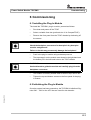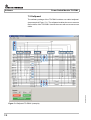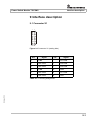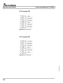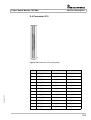
1
USER MANUAL
Power Switch Module
TS-PSM1
User Manual
for ROHDE & SCHWARZ Power Switch Module TS-PSM1
3rd Issue / 11.05 / GB 1143.0468.12
All rights, also translation into foreign languages, are reserved. No part of this manual is permitted
to be reproduced in any form (print, photocopy or any other method), also not for the preparation
of lectures, or processed, reproduced or made available using electronic systems without written
permission from ROHDE & SCHWARZ.
© The passing on to third parties and the reproduction of this documentation, utilisation and communication of its contents is not permitted unless specifically approved. Infringements will incur
claims for damages. All rights reserved in the case of the award of a patent or registration of a
design.
We draw to your attention that the names of software and hardware used in the Service Manual,
and the brand names of the respective companies are, in general, the subject of protection as
trademarks, or under proprietary rights, or patent law.
ROHDE & SCHWARZ GmbH & Co. KG
Corporate Headquarters
Mühldorfstr. 15
D-81671 München
Telephone:
Fax:
...49 (0)89/4129-13774
...49 (0)89/4129-13777
Printed in the Federal Republic of Germany. Errors excepted, subject to technical change without notice.
Safety Instructions
Attention!
Electrostatic
sensitive devices require
special care
Support Center
Telephone Europe:
+49 180 512 42 42
Telephone worldwide: +49 89 4129 13774
Fax:
+49 89 4129 13777
e-mail: [email protected]
If you have any technical queries about this Rohde &
Schwarz equipment, our Hotline at the Support Center of
Rohde & Schwarz Sales-GmbH will be glad to help.
Our team will discuss your queries and look for solutions to
your problems.
The Hotline is open Mondays to Fridays from 08.00 to 17.00
hrs.
For queries outside office hours, you can leave a message
or send a note via fax or email. We will then get back to you
as soon as possible.
Power Switch Modul TS-PSM1
Contents
Contents
1
Usage
1-1
1.1
General
1-1
1.2
Characteristics
1-2
2
View
2-1
3
Block Diagram
3-1
4
Layout
4-1
4.1
Mechanical Layout
4-1
4.2
Display Elements
4-2
Function Description
5-1
5.1
Signal Concept
5-1
5.2
System Functions
5-1
5.3
Flexibility
5-2
5.4
Compact Design
5-2
5.5
Noise Immunity
5-2
5
6
7
3rd Issue 11.05
8
9
Commissioning
6-1
6.1
Installing the Plug-In Module
6-1
6.2
Initializing the Plug-In Module
6-1
Software
7-1
7.1
Driver Software
7-1
7.2
Softpanel
7-2
7.3
TS-PSM1 Program Example
7-3
Self-Test
8-1
8.1
LED Test
8-1
8.2
Power-On Test
8-1
8.3
TSVP Self-Test
8-1
Interface description
9-1
9.1
9-1
Connector X1
3
Contents
Power Switch Modul TS-PSM1
9.2
Terminal X2
9-2
9.3
Terminal X3
9-2
9.4
Connector X10
9-3
9.5
Connector X20
9-5
9.6
Connector X30
9-6
10-1
3rd Issue 11.05
10 Specifications
4
Power Switch Modul TS-PSM1
Figures
Figures
View of the TS-PSM1 .........................................................................2-1
Figure 3-1
Block Diagram TS-PSM1 ...................................................................3-1
Figure 3-2
Functional Block Diagram TS-PSM1................................................3-2
Figure 4-1
Layout of Connectors and LED's .....................................................4-1
Figure 7-1
Softpanel TS-PSM1 (example) ..........................................................7-2
Figure 9-1
Connector X1 (mating side) ..............................................................9-1
Figure 9-2
Terminal X2 ........................................................................................9-2
Figure 9-3
Terminal X3 ........................................................................................9-2
Figure 9-4
Connector X10 (mating side) ............................................................9-3
Figure 9-5
Connector X20 (mating side) ............................................................9-5
Figure 9-6
Connector X30 (mating side) ............................................................9-6
3rd Issue 11.05
Figure 2-1
5
Power Switch Modul TS-PSM1
3rd Issue 11.05
Figures
6
Power Switch Modul TS-PSM1
Tables
Tables
Characteristics TS-PSM1 ..................................................................1-2
Table 4-1
Connectors on the TS-PSM1 ............................................................4-2
Table 4-2
Display elements on the TS-PSM1 ...................................................4-2
Table 7-1
Driver Installation TS-PSM1..............................................................7-1
Table 8-1
Statements about the LED Test........................................................8-1
Table 9-1
X1 Pinning Assignment.....................................................................9-1
Table 9-2
X10 Pinning Assignment...................................................................9-3
Table 9-3
X20 Pinning Assignment...................................................................9-5
Table 9-4
X30 Pinning Assignment...................................................................9-6
3rd Issue 11.05
Table 1-1
7
Power Switch Modul TS-PSM1
3rd Issue 11.05
Tables
8
Power Switch Module TS-PSM1
Usage
1 Usage
1.1 General
The ROHDE & SCHWARZ Power Switch Module TS-PSM1 is designed for interconnecting or distributing high voltages or current. Currents/voltages at all switching nodes can be measured or monitored
with the analog bus. These functions are particularly important when
the test component's current demand in both normal and standby mode
has to be measured.
The TS-PSM1 can be used in the CompactTSVP and the PowerTSVP
(TSVP = Test System Versatile Platform). It is fitted into the front of the
TSVP chassis.
The front connector ends flush with the front panel of the TSVP chassis
and is used for contacting the test products. An adapter frame can also
be used if necessary.
3rd Issue 11.05
At the back the TS-PSM1 is connected to the CAN/PXI bus and the analog bus of the TSVP chassis. The high power lines are taken to the
rear of the TS-PSM1 via connection terminals and a 12-pin plug connector.
1-1
Usage
Power Switch Module TS-PSM1
1.2 Characteristics
Characteristics TS-PSM1
Power switching module for supplies and loads
Switching module for high voltages (max. 60 V)
8 high power channels (max. 16 A)
10 low power channels (max. 2 A)
4 high power MUX channels 4 : 1 (max. 16 A)
Indirect current measurement on high power channels with shunt
Direct current measurement on all channels by R&S analog bus and
TS-PSAM plug-in module (<1 A)
Self-test of all relays by analog bus and TS-PSAM plug-in module
Control bus: CAN
For use in CompactTSVP and PowerTSVP
3rd Issue 11.05
Table 1-1 Characteristics TS-PSM1
1-2
Power Switch Module TS-PSM1
View
2 View
Figure 2-1 shows a view of the TS-PSM1 .
3rd Issue 11.05
Figure 2-1 View of the TS-PSM1
2-1
Power Switch Module TS-PSM1
3rd Issue 11.05
View
2-2
Power Switch Module TS-PSM1
Block Diagram
3 Block Diagram
3rd Issue 11.05
Figure 3-1 shows the block diagram of the TS-PSM1. A simplified view
of the functional block can be seen in Figure 3-2 .
Figure 3-1 Block Diagram TS-PSM1
3-1
Block Diagram
Power Switch Module TS-PSM1
3rd Issue 11.05
Figure 3-2 Functional Block Diagram TS-PSM1
3-2
Power Switch Module TS-PSM1
Layout
4 Layout
4.1 Mechanical Layout
The TS-PSM1 is designed as a long plug-in board for front mounting
in the TSVP chassis. The mounting depth is 300 mm, and the front panel is 4U in height.
Connector X20 is used to make the connections with the cPCI backplane / control backplane of the TSVP. Connector X30 connects the
TS-PSM1 with the analog bus backplane in the TSVP chassis. The
high power connections are routed across the rear connector X1 and
terminals X2, X3. Test products and peripherals are connected using
front connector X10 .
3rd Issue 11.05
Figure 4-1 Layout of Connectors and LED's
4-1
Layout
Power Switch Module TS-PSM1
Symbol
Use
X1
High Power Connector
X2
High Power Terminal
X3
High Power Terminal
X10
Front Connector
X20
PXI/Extension Connector
X30
Analog Bus Connector
Table 4-1 Connectors on the TS-PSM1
4.2 Display Elements
(see Figure 4-1 )
The front panel of the TS-PSM1 contains three light-emitting diodes
(LED's) with the following functions:
LED
Description
ERR
(red)
Fault condition:
Lights up when a fault is detected on the TS-PSM1 in the
power-on test after the supply voltage is switched on.
COM
(yellow)
Communication:
Lights up briefly when the TS-PSM1 is accessed via the
interface.
PWR
(green)
Power:
Lights up when all supply voltages are present.
Table 4-2 Display elements on the TS-PSM1
When voltage is powered up all three LED's light up for around 1 second. This ensures that the 5 V supply is present and that the LED's and
power-on test are functioning.
4-2
3rd Issue 11.05
LED Test:
Power Switch Module TS-PSM1
Function Description
5 Function Description
(see Section 3, Block Diagram and Functional Block Diagram)
5.1 Signal Concept
The special design of the TS-PSM1 guarantees the ideal guiding of
supply and load paths through the test system. Both “Force” channels
with high currents and “Sense“ channels of voltage/current sources are
guided across the TS-PSM1 to the components on test. In the opposite
direction, test components can be injected with loads with one or a
number of poles. With the High Power Multiplexers it is possible to select different load simulations that can be integrated in the TSVP chassis.
The currents and voltages can be measured and monitored at all
switching nodes with additional relays on the TS-PSM1 and the analog
bus (high currents with shunts).
5.2 System Functions
The system functions are implemented by a local processor with internal flash. An external SRAM is also provided. Communication with the
system controller in the CompactTSVP is conducted on the CAN bus.
The functions of the TS-PSM1 can be summarized as follows:
Analog function test
•
Connection of voltage/current sources
•
Connection of test component loads (original loads, simulated/
electronic loads)
•
Power Multiplexer
•
Switch simulation
3rd Issue 11.05
•
5-1
Function Description
Power Switch Module TS-PSM1
5.3 Flexibility
The construction of the TS-PSM1 and its wide range of voltages and
currents ensure a high level of flexibility and a broad range of applications. As well as being used in the ROHDE & SCHWARZ CompactTSVP and PowerTSVP, the TS-PSM1 can also be operated remotely
in the UUT adapter or in a load box.
Even complex, yet flexible load systems can be implemented with original loads and/or electronic loads by the multiple module-internal connection of power channels to form a high current bus in the PowerTSVP.
The high-power sources or loads are fed thru connector X1 to the UUT.
The preferred slot in the CompavctTSVP is slot 16. If single high power
switches are needed, the terminals X2 and X3 can be used to reconnect the second pole to the front connector. Application specific cable
and additional front panel are necessary. In the CompactTSVP, only
slot 16 allows usage of connector X1 to pass thru the signals from/to
the back.
5.4 Compact Design
The space-saving design of the TS-PSM1 (1 slot) with voltage/current
monitoring and self-test on the analog bus allows the creation of very
powerful and compact measurement and load systems with up to 12
modules in the CompactTSVP and 16 modules in the PowerTSVP.
These can be incorporated directly and hence very cost-effectively in
production cells.
Optimum response to electrical interference or rises in temperature is
achieved by the controller on the serial differential CAN bus (Controller
Area Network).
5-2
3rd Issue 11.05
5.5 Noise Immunity
Power Switch Module TS-PSM1
Commissioning
6 Commissioning
6.1 Installing the Plug-In Module
The install the TS-PSM1 plug-in module, proceed as follows:
•
Run down and power off the TSVP
•
Select a suitable front slot (preferred slot 16 in CompactTSVP).
•
Remove the front panel from the TSVP chassis by slackening off
the screws.
WARNING!
Check the backplane connectors for bent pins! Any bent pins
must be straightened!
Failure to do this may permanently damage the backplane!
•
Push in the plug-in module using moderate pressure
•
The top snap pin on the module must locate in the right-hand and
the bottom pin in the left-hand hole on the TSVP chassis
WARNING!
Use both hands to guide the module and carefully plug it into the
backplane connectors
•
The module is correctly located when a distinct 'stop' can be felt
•
Tighten the top and bottom screws on the front panel of the plugin module
6.2 Initializing the Plug-In Module
3rd Issue 11.05
Once the system has been powered up, the TS-PSM1 is initialized. Signals GA0 ... GA5 on the cPCI bus are used for slot detection.
6-1
Power Switch Module TS-PSM1
3rd Issue 11.05
Commissioning
6-2
Power Switch Module TS-PSM1
Software
7 Software
7.1 Driver Software
A LabWindows CVI driver is provided for the TS-PSM1 . This driver satisfies the IVI Switch specification. The driver is part of the ROHDE &
SCHWARZ GTSL software. All the functions of the driver are described
fully in the on-line help and in the LabWindows CVI Function Panel.
The following software modules are installed during driver installation:
Module
Path
Remarks
rspsm1.dll
<GTSL Directory>\Bin
Driver
rspsm1.hlp
<GTSL Directory>\Bin
Help file
rspsm1.fp
<GTSL Directory>\Bin
LabWindows CVI Function Panel file,
Function Panels for CVI development environment
rspsm1.sub
<GTSL Directory>\Bin
LabWindows CVI attribute file. This files is
needed by some „Function Panels“.
rspsm1.sub
<GTSL Directory>\Bin
Import library
rspsm1.h
<GTSL Directory>\Include
Header file for the driver
Table 7-1 Driver Installation TS-PSM1
NOTE:
3rd Issue 11.05
The IVI and VISA libraries of National Instruments are needed to
run the driver.
7-1
Software
Power Switch Module TS-PSM1
7.2 Softpanel
Figure 7-1 Softpanel TS-PSM1 (example)
7-2
3rd Issue 11.05
The software package of the TS-PSM1 includes a so-called softpanel
(see example in Figure 7-1). The softpanel enables the user to execute
the functions of the TS-PSM1 listed in the menu with on-screen mouse
clicks.
Power Switch Module TS-PSM1
Software
7.3 TS-PSM1 Program Example
/*
Simple connection between ABa1 and ABb1 with TS-PSM1 in Slot 16
The coding rules of a GTSL software like
allocating and locking the resource, or error handling
are not considered in this example.
It´s just to show the function calls to get the connection.
*/
#include "rspsm1.h"
static ViStatus
/* rspsm1 ivi-driver header file
*/
s_status;
main()
{
/*
Creates a new IVI instrument driver and optionally sets the initial
state of the session attributes.
"CAN0::0::1::16": CAN board 0, Bus Controller 0, Frame 1, Slot 16
*/
s_status = rspsm1_InitWithOptions ("CAN0::0::1::16", VI_TRUE,
VI_TRUE,
"", & handle);
/*
This function creates a path between channel ABa1 and LABa1.
The driver calculates the shortest path between the two channels.
*/
s_status = rspsm1_Connect (handle, "ABa1", "LABa1");
s_status = rspsm1_Connect (handle, "ABb1", "LABb1");
s_status = rspsm1_Connect (handle, "CH1com", "LABa1");
s_status = rspsm1_Connect (handle, "CH1no", "LABb1");
s_status = rspsm1_Connect (handle, "CH1com", "CH1no");
3rd Issue 11.05
/*
Connection between ABa1 and ABb1 exists.
*/
/*
Opens the path between Channel ABa1 and LABa1.
*/
s_status = rspsm1_Disconnect (handle, "CH1com", "CH1no");
7-3
Software
Power Switch Module TS-PSM1
s_status = rspsm1_Disconnect (handle, "CH1com", "LABa1");
s_status = rspsm1_Disconnect (handle, "CH1no", "LABb1");
s_status = rspsm1_Disconnect (handle, "ABa1", "LABa1");
s_status = rspsm1_Disconnect (handle, "ABb1", "LABb1");
s_status = rspsm1_close (handle);
3rd Issue 11.05
}
7-4
Power Switch Module TS-PSM1
Self-Test
8 Self-Test
The TS-PSM1 has a built-in self-test capability. The following tests are
possible:
•
LED Test:
•
Power-on test
•
TSVP Self-Test
8.1 LED Test
After power-on, all three LED's light up for around one second to indicate that the 5 V supply is present, all LED's are working and the poweron test was successful. The following statements can be made about
the different LED statuses:
LED
Description
One LED
does not light
up
Hardware problem on the module
No LED's
light up
No +5V supply
Table 8-1 Statements about the LED Test
8.2 Power-On Test
The power-on test runs at the same time as the LED test. The red LED
lights up if a fault is found on the module. This is just a test of the
firmware of the TS-PSM1 .
3rd Issue 11.05
8.3 TSVP Self-Test
The TSVP self-test runs an in-depth test on the module and generates
a detailed log.
8-1
Self-Test
Power Switch Module TS-PSM1
The TS-PSAM modules is used as a measuring unit of R&S modules
in the TSVP. The correct operation of the modules is ensured by measurements on the analog bus.
NOTE:
3rd Issue 11.05
You will find information about starting the self-test and on the
sequence of necessary steps in the Service Manual.
8-2
Power Switch Module TS-PSM1
Interface description
9 Interface description
9.1 Connector X1
1
7
6
12
Figure 9-1 Connector X1 (mating side)
Pin
Signal
Pin
Signal
1
LPBA
7
CH1 COM
2
CH2 COM
8
CH6 COM
3
CH3 COM
9
CH4 COM
4
LPBB
10
LPBD
5
CH5 COM
11
CH7 COM
6
CH8 COM
12
LPBC
3rd Issue 11.05
Table 9-1 X1 Pinning Assignment
9-1
Interface description
Power Switch Module TS-PSM1
9.2 Terminal X2
Figure 9-2 Terminal X2
9.3 Terminal X3
3rd Issue 11.05
Figure 9-3 Terminal X3
9-2
Power Switch Module TS-PSM1
Interface description
9.4 Connector X10
1
32
A BC
Figure 9-4 Connector X10 (mating side)
3rd Issue 11.05
Pin
A
B
C
1
CH1_NO
CH1_NO
CH1_NO
2
CH1_NO
CH1_NO
CH1_NO
3
CH1_NO
CH1_NO
CH1_NO
4
CH2_NO
CH2_NO
CH2_NO
5
CH2_NO
CH2_NO
CH2_NO
6
CH2_NO
CH2_NO
CH2_NO
7
CH9_NO
CH10_NO
CH11_NO
8
CH9_COM
CH10_COM
CH11_COM
9
CH3_NO
CH3_NO
CH3_NO
10
CH3_NO
CH3_NO
CH3_NO
11
CH3_NO
CH3_NO
CH3_NO
12
CH4_NO
CH4_NO
CH4_NO
Table 9-2 X10 Pinning Assignment
9-3
Interface description
Power Switch Module TS-PSM1
Pin
A
B
C
13
CH4_NO
CH4_NO
CH4_NO
14
CH4_NO
CH4_NO
CH4_NO
15
CH12_NO
CH13_NO
CH14_NO
16
CH12_COM
CH13_COM
CH14_COM
17
CH5_NO
CH5_NO
CH5_NO
18
CH5_NO
CH5_NO
CH5_NO
19
CH5_NO
CH5_NO
CH5_NO
20
CH6_NO
CH6_NO
CH6_NO
21
CH6_NO
CH6_NO
CH6_NO
22
CH5_NO
CH6_NO
CH6_NO
23
CH15_NO
CH16_NO
GND
24
CH15_COM
CH16_COM
GND
25
CH7_NO
CH7_NO
CH7_NO
26
CH7_NO
CH7_NO
CH7_NO
27
CH7_NO
CH7_NO
CH7_NO
28
CH8_NO
CH8_NO
CH8_NO
29
CH8_NO
CH8_NO
CH8_NO
30
CH8_NO
CH8_NO
CH8_NO
31
IL1_NO
IL2_NO
GND
32
IL1_COM
IL2_COM
CHA-GND
Table 9-2 X10 Pinning Assignment
Note:
3rd Issue 11.05
Signals in bold print are High Power
9-4
Power Switch Module TS-PSM1
Interface description
9.5 Connector X20
22
F E D C BAZ
Figure 9-5 Connector X20 (mating side)
NC = not connected, NP = not populated
3rd Issue 11.05
Pin
22
21
20
19
18
17
16
15
14
13
12
11
10
9
8
7
6
5
4
3
2
1
F
GND
GND
GND
GND
GND
GND
GND
GND
E
D
C
B
A
GA0
GA1
GA2
GA3
GA4
PXI_LBR3
PXI_LBR2
PXI_LBR1
GA5
PXI_LBR0
PXI_LBL1
GND
PXI_LBL0
AUX1
AUX2
AUX1
AUX2
PXI_LBL3
GND
PXI_LBL2
PXI_TRIG3
PXI_TRIG6
GND
PXI_TRIG5
PXI_TRIG4
PXI_CLK10
AUX4
AUX3
GND
PXI_TRIG2
PXI_TRIG7
GND
AUX5
PXI_TRIG0
PXI_TRIG1
+5V
+5V
AUX6
GND
NC
NC
NP
CH9_COM
CH13_COM
NP
IL1_COM
NC
CH10_COM
CH14_COM
NC
NC
CH11_COM
CH15_COM
NC
IL2_COM
NC
CH12_COM
CH16_COM
NC
Z
GND
GND
GND
GND
GND X20
GND
GND
GND
NC
C
NC
O
NP
N
NP
N
NC
E
NC
C
NC
T
NC
O
NC
R
NC
NC
NC
GND
GND
GND
RSA0
RRST#
+12V
GND
RSDO
+12V
RSDI
RSA1
+5V
RSCLK
+5V
CAN_L
CAN_H
GND
RCS#
Rear I/O
GA3..0 at GND or N.C.
GND
GND
GND
Rear I/O incompatible PXI
PXI Signals
R&S Rear IO control (SPI)
GA5..4 at jumper field. GA5 only TS-PWA3
Table 9-3 X20 Pinning Assignment
9-5
Interface description
Power Switch Module TS-PSM1
9.6 Connector X30
Figure 9-6 Connector X30 (mating side)
Pin
7
E
A
IL1_x
ABc1
ABa1
ABb1
ABc2
2
1
B
GND
4
3
C
IL2_x
6
5
D
ABb2
ABa2
ABd2
ABd1
Table 9-4 X30 Pinning Assignment
Note:
3rd Issue 11.05
IL1_x = IL1 of the slot
9-6
Power Switch Module TS-PSM1
Specifications
10 Specifications
NOTE:
In the event of any discrepancies between data in this manual
and the technical data in the data sheet, the data sheet takes
precedence.
Interfaces
Control Bus
CAN 2.0b (1 Mbit/s)
UUT Connector (Front)
DIN41612, 96 pins
Rear I/O connector
cPCI, 110 pins
High Power Switching Channels
Number/Relay Type
8 / Zettler AZ764
Contacts
8 x SPST
Max. switching voltage
60 VDC / 42 VAC
Max. switching current
12 A rms (continuously), 16 A pulsed max. 60 s
(duty cycle: 1 period on / 3 periods off)
Max. switching capacity
480 W
On-time (typ.)
10 ms
Off-time (typ.)
3 ms
Switching cycles (mech.)
3 x 10⁷
Current measurement (indirect)
8 x shunt, 10 mOhm
Current measurement (direct)
max. 1A / 10W with analog bus and TS-PSAM
3rd Issue 11.05
High Power Multiplexer
Number/Relay Type
16 / Zettler AZ764
Contacts
4 x 4-to-1
Max. switching voltage
60 VDC / 42 VAC
Max. switching current
12 A rms (continuously), 16 A pulsed max. 60 s
(duty cycle: 1 period on / 3 periods off)
10-1
Specifications
Max. switching capacity
Power Switch Module TS-PSM1
480 W
Low Power Interface
Number/Relay Type
10 / Zettler AZ832
Contacts
10 x SPST
Max. switching voltage
60 VDC / 42 VAC
Max. switching current
2A
Max. switching capacity
150 W
On-time (typ.)
3 ms
Off-time (typ.)
2 ms
Switching cycles (mech.)
2 x 10⁷
Current measurement (direct)
max. 1A / 10W with analog bus and TS-PSAM
Monitor Switching Channels
Number/Relay Type
6 / Meder RM-05
Contacts
12 x 4-to-1
Max. switching voltage
60 VDC / 42 VAC
Max. switching current
1 A (1.5 A load rating)
Max. switching capacity
10 W
On-time (typ.)
0.5 ms
Off-time (typ.)
0.2 ms
Switching cycles (mech.)
1 x 10⁹
10-2
EMC
according to EMC Directive 89/336/EEC and Standard
EN61326
Safety
CE, EN61010 Part 1
Shock
40 g, MIL-STD-810, MIL-T-28800, class 3 and class 5
Sinusoidal Vibration
5 Hz to 55 Hz
55 Hz to 150 Hz
2 g, MIL-T-28800D, class 5
0.5 g, MIL-T-28800D, class 5
3rd Issue 11.05
Environmental conditions
Power Switch Module TS-PSM1
Specifications
Noise
10 Hz to 300 Hz
1.2 g
Humidity
+25 °C / +40 °C, 95% humidity
General Data
Dimensions
316 x 174 x 20 mm
Weight
780 g
Nominal temperature range
+5 °C to +40 °C
Operating temperature range
0 to +50°C
Storage temperature range
-40 °C to +70 °C
Power consumption
22.5 W max.
Order number
Power Switching Module TS-PSM1
1143.0139.02
Software
3rd Issue 11.05
GTSL basic software, CVI driver
10-3