1
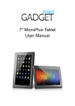
1
SABRE Lite Hardware User Manual
Revision History
Date
10-27-2011
11-07-2011
Revision
1.0
1.1
Description
First Draft
Updated Section 2/Modified Picture
Revision 1.1
2
1 Contents
1 Contents ....................................................................................................................................... 2
2 Overview ...................................................................................................................................... 3
3 Electrical Characteristics ............................................................................................................. 3
4 Connector Details......................................................................................................................... 4
5 Mounting .................................................................................................................................... 11
Revision 1.1
3
2 Overview
Freescale and Boundary Devices are excited to announce the availability of the i.MX6x SABRE
Lite Board, a low-cost development platform featuring the powerful i.MX 6Quad Application
Processor. The hardware specifications for the Sabre Lite board are the following:
•
•
•
•
•
•
•
•
•
•
•
•
•
•
•
•
Quad-Core ARM® Cortex A9 processor at 1GHz per core
1GByte of 64-bit wide DDR3 @ 532MHz
Three display ports (RGB, LVDS, and HDMI 1.4a)
Two camera ports (1xParallel, 1x MIPI CSI-2)
Multi-stream-capable HD video engine delivering H.264 1080p60 decode,1080p30
encode and 3-D video playback in HD
Triple Play Graphics system consisting of a Quad-shader 3D unit, and a separate 2-D and
separate OpenVG Vertex acceleration engine for superior 3D, 2D and user interface
acceleration
Serial ATA 2.5 (SATA) at 3Gbps
Dual SD 3.0/SDXC card slots
PCIe port (1 lane)
Analog (headphone/mic) and Digital (HDMI) audio
10/100/Gb Ethernet
10-pin JTAG interface
3 High speed USB ports (2xHost, 1xOTG)
1xCAN2 port
I2C
General Purpose I/O for Device Control
3 Electrical Characteristics
Parameter
Min Typ Max Unit
Main Input Voltage
TBD
5
TBD
V
Power Consumption*
5
TBD
W
CPU Clock
1.0
1.0 GHz
*The Power Consumption refers to a single board with no other peripherals plugged in.
Revision 1.1
4
4 Connector Details
Figure 1 shows the details of each connector.
Revision 1.1
5
4.1 Standard Connectors
The list of industry standard connectors with known pin outs is the following:
Ref Designator
J3
J4
J8
J9
J10
J18
J20
J21
J24
Function
USB OTG
HDMI (DVI Signals)
Headphone Jack
Mic IN
DC Power Jack
Standard SD Slot
microSD Slot
SATA
10/100 Ethernet/2xUSB Host
4.2 Custom Connectors
The SABRE Lite board has a wide variety of peripheral interfaces available via custom
connectors.
J1: USB (Molex 53047-0410)
Pin# Function
1
+5V
2
USBDN_DM3
3
USBDN_DP3
4
GND
J5: Camera (AVX 086210033340800)
Pin# Function
1
GND
2
D19
3
D18
4
D17
5
D16
6
D15
7
D14
8
D13
9
D12
10 D11
11 D10
12 D9
13 D8
14 SCL
15 SDA
Revision 1.1
6
16
17
18
19
20
21
22
23
24
25
26
27
28
29
30
31
32
33
GND
GPIO_3_CLKO2
GND
2.5V
2.5V
2.5V
2.5V
GND
CSI0_DATA_EN
GND
CSI0_RST
CSI0_VSYNC
CSI0_HSYNC
GND
CSI0_PIXCLK
GPIO_6
GND
GPIO1_16
J6: LVDS (Hirose DF14-20P-1.25H)
Pin# Function
1
3.3V
2
3.3V
3
GND
4
GND
5
TX0_N
6
TX0_P
7
GND
8
TX1_N
9
TX1_P
10 GND
11 TX2_N
12 TX2_P
13 GND
14 CLK_N
15 CLK_P
16 GND
17 TX3_N
18 TX3_P
19 DISP0_CONTRAST
20 PWM4
J7: I2C/GPIO (Molex 53047-0710)
Pin# Function
1
+5V
Revision 1.1
7
2
3
4
5
6
7
+5V
+5V
GPIO9
I2C3_SDA
I2C3_SCL
GND
J12: Boot Mode Switches (Molex 52991-0408)
Pin# Function
1
EIM_A23
2
EIM_DA0
3
EIM_A22
4
EIM_DA1
5
EIM_A21
6
EIM_DA2
7
EIM_A20
8
EIM_DA3
9
EIM_A19
10 EIM_DA4
11 EIM_A18
12 EIM_DA5
13 EIM_A17
14 EIM_DA6
15 EIM_A16
16 EIM_DA7
17 EIM_EB3
18 EIM_DA8
19 EIM_EB2
20 EIM_DA9
21 EIM_RW
22 EIM_DA10
23 EIM_EB1
24 EIM_DA11
25 EIM_EB0
26 GND
27 EIM_LBA
28 EIM_DA12
29 GND
30 DSI_D1M
31 EIM_WAIT
32 EIM_DA13
33 GND
34 GND
35 EIM_A24
36 EIM_DA14
Revision 1.1
8
37
38
39
40
+3.3V
GND
+3.3V
EIM_DA15
J13: JTAG (FCI 20021121-00010T4LF)
Pin# Function
1
+3.3V
2
JTAG_TMS
3
GND
4
JTAG_TCK
5
GND
6
JTAG_TDO
7
JTAG_MOD
8
JTAG_TDI
9
JTAG_nTRST
10 BRESET_N
J14: Android Buttons (Molex 53047-0810)
Pin# Function
IMX6 Pad Name
1
ON/OFF
2
KEY_VOL_UP
GPIO_18
3
HOME
NANDF_D4
4
SEARCH
NANDF_D3
5
BACK
NANDF_D2
6
MENU
NANDF_D1
7
KEY_VOL_DN
GPIO_19
8
GND
J15: Parallel RGB (Omron XF2M-4015-1A)
Pin# Function
1
GND
2
GND
3
GND
4
DISP0_CNTRST
5
R0
6
R1
7
R2
8
R3
9
R4
10 R5
11 R6
12 R7
13 G0
14 G1
Revision 1.1
9
15
16
17
18
19
20
21
22
23
24
25
26
27
28
29
30
31
32
33
34
35
36
37
38
39
40
G2
G3
G4
G5
G6
G7
B0
B1
B2
B3
B4
B5
B6
B7
GND
DISP0_CLK
GND
DISP0_HSYNC
DISP0_VSYNC
DISP0_DRDY
I2C3_SCL
I2C3_SDA
PWM1
+5V
+5V
+5V
J16: MIPI (Molex 52991-0408)
Pin# Function
1
CSI_D0M
2
+5V
3
CSI_D0P
4
+5V
5
GND
6
I2C2_SDA
7
CSI_D1M
8
I2C2_SCL
9
CSI_D1P
10 PWM3
11 GND
12 MIPI_BAKLGT_ON
13 CSI_D2M
14 NANDF_D5
15 CSI_D2P
16 DSI_D0P
Revision 1.1
10
17
18
19
20
21
22
23
24
25
26
27
28
29
30
GND
DSI_D0M
CSI_D3M
GND
CSI_D3P
DSI_CLK0P
GND
DSI_CLK0M
CSI_CLK0M
GND
CSI_CLK0P
DSI_D1P
GND
DSI_D1M
J17: COM1 & COM2 (Molex 53047-0610)
Pin# Function
1
UART1 TX
2
+5V
3
GND
4
UART2 TX
5
UART2 RX
6
UART1 RX
J19: SATA Power (Tyco 640457-3)
Pin# Function
1
+3.3V
2
GND
3
+5V
J22: CAN Interface (Molex 53047-0810)
Pin# Function
1
+5V
2
VSUP
3
GND
4
CANL
5
CANH
6
GND
7
INH
8
GND
J23: PCIe (Molex 53047-0710)
Pin# Function
1
+3.3V
2
PCIE_RXM
Revision 1.1
11
3
4
5
6
7
PCIE_RXP
PCIE_TXM
PCIE_TXP
GND
GND
5 Mounting
The overall dimensions of the SABRE Lite board are 3.25”x3.25”
Revision 1.1