1
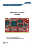
MarS Board
Freescale i.MX6Dual Core ARM Evaluation Platform
By
User Manual
Version 1.0
Dated: 5th Dec 2013
Copyright Statement:
MarS Board and its related intellectual property are owned by
Shenzhen Embest Technology Co., Ltd.
Shenzhen Embest Technology has the copyright of this
document and reserves all rights. No part of the document should
not be modified, distributed or duplicated in any approach and form
without written permission issued by Embest Technology Co., Ltd.
The use of Microsoft, MS-DOS, Windows, Windows95,
Windows98, Windows2000 and Windows embedded CE 6.0 are
authorized by Microsoft.
Revision History:
Version
Date
Description
1.0
05/12/2013
Original Version
Table of Contents
1 Product Overview .............................................................. 1
1.1 Introduction ................................................................ 1
1.2 Kit Contents ................................................................ 1
1.3 Board Interfaces .......................................................... 2
1.4 System Block Diagram ................................................. 3
1.5 Physical Dimensions (mm) ............................................ 4
2 Hardware Features ............................................................ 5
2.1 Processor ................................................................... 5
2.2 On-Board Memory ....................................................... 5
2.3 On-Board Interfaces .................................................... 5
2.4 On-Board Interface Signals ........................................... 6
2.5 Operational Parameters ................................................ 6
3 Hardware Details ............................................................... 7
3.1 CPU Introduction ......................................................... 7
3.2 Clock Signals .............................................................. 7
3.3 Reset Signal................................................................ 7
3.4 General Interfaces ....................................................... 8
3.5 Display Interface ......................................................... 8
3.6 3D Graphics Acceleration System................................... 8
3.7 Peripheral ICs ............................................................. 8
3.7.1 eMMC Flash NCEMBM11-04G ................................. 8
3.7.2 DDR H5TQ2G63DFR-H9C ...................................... 9
3.7.3 AR8035 Ethernet PHY ........................................... 9
3.7.4 FE1.1 USB Hub .................................................... 9
3.7.5 FT232RQ USB to UART Chip ................................ 10
3.8 Hardware Interfaces on Mars Board ............................. 10
3.8.1 Power Jack (J8) ................................................. 10
3.8.2 HDMI Interface (J1) ........................................... 11
3.8.3 LVDS Interface (J3) ............................................ 11
3.8.4 USB OTG Interface (J7) ...................................... 12
3.8.5 USB Debug Interface (J9) ................................... 12
3.8.6 Ethernet Interface (J2) ....................................... 13
3.8.7 USB Hub Interface (Hub1) .................................. 13
3.8.8 USB Hub Extension Interface (J21) ...................... 14
3.8.9 TF Card Interface (J13)....................................... 14
3.8.10 LCD Interface (J12) .......................................... 14
3.8.11 AUDMUX Interface (J11) ................................... 16
3.8.12 CAN1 Interface (J11) ........................................ 16
3.8.13 CAN2 Interface (J11) ........................................ 16
3.8.14 ECSPI2 Interface (J10) ..................................... 16
3.8.15 I2C1 Interface (J11) ......................................... 17
3.8.16 I2C3 Interface (J11) ......................................... 17
3.8.17 IPU1 (Image Processing Unit 1) Interface (J11) ... 17
3.8.18 KPP Keyboard Interface (J11) ............................ 17
3.8.19 PWM Interface (J10 & J11) ................................ 18
3.8.20 GPMI (General Purpose Memory Interface) (J10) .. 18
3.8.21 SPDIF (Sony/Philips Digital Interface) (J10)......... 18
3.8.22 UART1 Interface (J11) ...................................... 19
3.8.23 UART3 Interface (J10) ...................................... 19
3.8.24 UART4 Interface (J11) ...................................... 19
3.8.25 UART5 Interface (J11) ...................................... 19
3.8.26 USDHC1 Interface (J10) .................................... 20
3.8.27 ESAI (J10 & J11) .............................................. 20
4 Software Features ........................................................... 21
4.1 Software Introduction ................................................ 21
4.2 Linux Components ..................................................... 21
4.3 Android Components .................................................. 22
4.4 Setting up HyperTerminal ........................................... 23
4.5 Downloading and Running an Operating System ............ 24
4.6 Micrium uC/OS System Demonstration ....................... 28
4.7 Display Mode Configurations of Linux & Android Systems 28
4.7.1 Display with 4.3” LCD ......................................... 30
4.7.2 Display with 7” LCD ............................................ 30
4.7.3 Display with 9.7” LVDS ....................................... 30
4.7.4 Display with VGA8000 ........................................ 30
4.7.5 Display with HDMI.............................................. 31
4.7.6 Dual Display with LCD & HDMI ............................. 31
4.7.7 Dual Display with LVDS & HDMI ........................... 32
5 Making Images ................................................................ 33
5.1 Making Images for Linux ............................................ 33
5.1.1 Getting Tools and Source Code ............................ 33
5.1.2 Compiling System Images ................................... 34
5.2 Making Images for Android ......................................... 35
5.2.1 Getting Repo Source Code .................................. 35
5.2.2 Compiling System Images ................................... 36
6 Appendix 1 – Installing Ubuntu Linux System ................. 38
6.1 Installing VirtualBox ................................................... 38
6.2 Installing Ubuntu Linux System ................................... 43
1 Product Overview
1.1 Introduction
MarS Board is a low cost, highly integrated evaluation board designed by
Embest Technology and based on Freescale’s i.MX 6Dual ARM Cortex-A9
processor. The i.MX 6Dual integrates an ARM Cortex-A9 core of up to 1GHz,
2D and 3D graphics processors and 3D 1080p video processor. MarS Board
is featured with abundant interfaces such as HDMI, LVDS, mini USB OTG,
mini USB debug, RJ45, USB host, TF card and LCD display to help developers
from different fields including netbooks, all-in-one PCs, high-end mobile
Internet devices, handhold computers, portable media players, game
consoles and portable navigation devices.
1.2 Kit Contents
MarS Board
Optional accessories package including:
HDMI Cable
Mini USB Cable
5V@4A power adapter
4GB TF Card
Gigabit Ethernet line
Optional 4.3” or 7” touchscreen LCD
Optional 9.7” touchscreen TFT (LVDS)
1.3 Board Interfaces
Figure 1: MarS Board Interfaces
1.4 System Block Diagram
Figure 2: MarS Board System Block Diagram
1.5 Physical Dimensions (mm)
Figure 3: MarS Board Hardware Dimensions
2 Hardware Features
2.1 Processor
i.MX 6Dual integrated ARM Cortex™-A9 core
32 KB L1 Instruction Cache
32 KB L1 Data Cache
Private Timer and Watchdog
Cortex-A9 NEON MPE (Media Processing Engine) Coprocessor
2D/3D Graphics Processors
2.2 On-Board Memory
4GByte eMMC
Four sets of 256MB DDR3 SDRAM (1GB in total)
2.3 On-Board Interfaces
HDMI Interface
LVDS Interface
LCD Interface
Two 480Mbps High-Speed USB2.0 Hub Interfaces
Two 480Mbps High-Speed USB2.0 Header Interfaces
480Mbps High-Speed USB2.0 OTG Interface
COM-USB Debug (com2) Interface
TF Card Interface
10/100M/1Gbps RJ45 Network Interface
Boot Mode Interface
Reset Button
2.4 On-Board Interface Signals
AUDMUX (Digital Audio Multiplexer) Signal
Two CAN Signals
ECSPI2 (Enhanced Configurable SPI) Signal
Two I2C Signals
Camera/ Parallel signal, up to 16 bit
KPP (Keypad Port) Signal
PWM (Pulse Width Modulation) Signal
GPMI (General Purpose Memory Interface) Signal
SPDIF (Sony/Philips Digital Interface) Signal
Four UART Signals
USDHC1 (Ultra Secured Digital Host Controller) Signal
ESAI (Enhanced Serial Audio Interface) Signal
Note:
The pins of some of the interfaces listed above are multiplexed. Please refer to
relevant data sheets for the processor and product schematics.
2.5 Operational Parameters
Dimensions: 65mm x 102mm
Operation Temperature: 0°C ~ 70°C
Operating Humidity: 20% ~ 90% (Non-condensing)
Power Supply: 5V
3 Hardware Details
This chapter will describe the hardware composition of MarS Board by briefly
introducing the CPU, peripheral ICs and the pinouts of the many interfaces
on the product.
3.1 CPU Introduction
i.MX 6Dual is an ARM Cortex-A9-based dual-core processor from Freescale.
It runs at up to 1GHz, integrates 2D/3D graphics, a 3D 1080p video
processor and power management. The i.MX 6Dual also provides 64-bit
DDR3/LVDDR3/LVDDR2-1066 interfaces as well as many other interfaces
for devices such as such as HD displays and cameras.
3.2 Clock Signals
The clock signals of the i.MX 6Dual include a 32.768 KHz RTC clock and a 24
MHz external clock;
RTC Clock: generated by an external crystal for low-frequency
calculation;
External Clock: used to generate main clock signal for PLL,
CMM and other modules;
3.3 Reset Signal
The reset signal is determined by POR_B of CPU; a low level signal trigger
resetting.
3.4 General Interfaces
General interfaces include 7 sets of GPIOs, each providing 32 dedicated
GPIO pins (with the exception of GPIO7 which has 14 pins), and therefore
the total pin number of GPIOs can be up to 206.
3.5 Display Interface
Parallel 24-bit RGB interface supporting 60Hz WUXGA output
Two LVDS interfaces supporting up to 165 MP/s output
HDMI 1.4 interface
MIPI/DSI interface with 1Gbps output rate
3.6 3D Graphics Acceleration System
The i.MX 6Dual integrates a GPU3Dv4 3D GPU (graphics processing unit)
which provides hardware acceleration for 3D graphics algorithms and allows
desktop quality interactive graphics applications to reach resolutions of up to
1080p. The GPU3D supports OpenGL ES 2.0, including extensions; OpenGL
ES 1.1, and OpenVG 1.1.
Additionally, the i.MX 6Dual also has a GPUVGv2 vector GPU which provides
hardware acceleration for 2D graphics algorithms.
3.7 Peripheral ICs
3.7.1 eMMC Flash NCEMBM11-04G
The NCEMBM11-04G is an eMMC flash memory IC included on the MarS
Board with 4GB memory space. The IC supports high-speed DDR data
transfer at a clock frequency of up to 52MHz, as well as three widths of data
line: 1-bit (default), 4-bit and 8-bit. The synchronous power management
allows the IC to feature fast boot, automatic termination and sleep modes.
The NCEMBM11-04G also supports high-speed, dual-data-transfer boot
mode.
3.7.2 DDR H5TQ2G63DFR-H9C
The H5TQ2G63DFR-H9C is a DDR3 SDRAM IC included on the MarS Board;
with 256MB memory space it is suited for high-capacity and high-bandwidth
applications. It supports differential clock input, differential data strobe,
automatic refresh and asynchronous pin reset. The MarS Board contains
four H5TQ2G63DFR-H9C ICs adding up to 1GB of available memory.
3.7.3 AR8035 Ethernet PHY
The AR8035 is a single port 10/100/1000 Mbps tri-speed Ethernet PHY
featuring low power consumption and low cost. AR8035 supports the
MAC.TM RGMII interface and the IEEE 802.3az-2010, Energy Efficient
Ethernet (EEE) standard through proprietary SmartEEE technology;
improving energy efficiency in systems using legacy MAC devices without
802.3az support. Using the AR8035 the MarS Board can be either connected
to a hub via a straight-through network cable, or to a PC via a cross-over
network cable.
3.7.4 FE1.1 USB Hub
The FE1.1 is a USB 2.0 high-speed 4-port hub solution. It uses USB3320 to
provide 4 extended USB interfaces with support for high-speed (480MHz),
full-speed (2MHz) and low-speed (1.5MHz) modes.
3.7.5 FT232RQ USB to UART Chip
The FT232RQ is a USB-to-UART chip which powers the mini USB debug
interface on the MarS Board. It integrates a 1024-bit internal EEPROM and
CBUS I/O configuration; and supports data transfer rates from 300 baud to
3 Mbaud at TLL levels.
3.8 Hardware Interfaces on Mars Board
Figure 4: Hardware Interfaces on the MarS Board
3.8.1 Power Jack (J8)
Pins
Definitions
Descriptions
1
GND
GND
2
+5V
Power supply (+5V) 4A (Type)
3
+5V
Power supply (+5V) 4A (Type)
3.8.2 HDMI Interface (J1)
Pins
Definitions
Descriptions
1
DAT2+
TMDS data 2+
2
DAT2_S
TMDS data 2 shield
3
DAT2-
TMDS data 2-
4
DAT1+
TMDS data 1+
5
DAT1_S
TMDS data 1 shield
6
DAT1-
TMDS data 1-
7
DAT0+
TMDS data 0+
8
DAT0_S
TMDS data 0 shield
9
DAT0-
TMDS data 0-
10
CLK+
TMDS data clock+
11
CLK_S
TMDS data clock shield
12
CLK-
TMDS data clock-
13
NC
NC
14
NC
NC
15
SCL
IIC master serial clock
16
SDA
IIC serial bidirectional data
17
GND
GND
18
5V
5V
19
HPLG
Hot plug and play detect
3.8.3 LVDS Interface (J3)
Pins
Definitions
Descriptions
1
3V3
+3.3V
2
LVDS_TX2_P
LVDS Data2+
3
LVDS_TX2_N
LVDS Data2-
4
GND
GND
5
LVDS_TX1_P
LVDS Data1+
6
LVDS_TX1_N
LVDS Data1-
7
GND
GND
8
LVDS_TX0_P
LVDS Data0+
9
LVDS_TX0_N
LVDS Data-
10
GND
GND
11
LVDS_CLK_P
LVDS_CLK+
12
LVDS_CLK_N
LVDS_CLK-
13
LCD_PWR_EN
Touch Reset Signal
14
Touch_Int
Touch Interrupt Signal
15
I2C_SCL
IIC Master Serial Clock
Pins
Definitions
Descriptions
16
I2C_SDA
IIC Master Serial Data
17
LED_PWR_EN
Backlight Enable
18
5V
+5V
19
PWM
Pulse Width Modulation
3.8.4 USB OTG Interface (J7)
Pins
Definitions
Descriptions
1
VBUS
+5V
2
DN
USB Data-
3
DP
USB Data+
4
ID
USB ID
5
GND
GND
3.8.5 USB Debug Interface (J9)
Pins
Definitions
Descriptions
1
VBUS
+5V
2
DN
USB Debug Data-
3
DP
USB Debug Data+
4
NC
NC
5
GND
GND
3.8.6 Ethernet Interface (J2)
Pins
Definitions
Descriptions
1
TD1+
TD1+ output
2
TD1-
TD1- output
3
TD2+
TD2+ output
4
TD2-
TD2- output
5
TCT
2.5V Power for TD
6
RCT
2.5V Power for RD
7
RD1+
RD1+ input
8
RD1-
RD1- input
9
RD2+
RD2+ input
10
RD2-
RD2- input
11
GRLA
Green LED link signal
12
GRLC
Power supply for Green LED
13
YELC
Yellow LED action signal
14
YELA
Power supply for Yellow LED
3.8.7 USB Hub Interface (Hub1)
Pins
Definitions
Descriptions
1
APV
5V power for HUB A
2
AD-
USB HUB A Data-
3
AD+
USB Debug Data+
4
GNDA
USB HUB A GND
5
BPV
5V power for HUB B
6
BD-
USB HUB B Data-
7
BD+
USB HUB B Data+
8
GNDB
USB HUB B GND
3.8.8 USB Hub Extension Interface (J21)
Pins
Definitions
Descriptions
1
PWR2
5V power for HUB 2
2
PWR1
5V power for HUB 1
3
DM2
USB HUB 2 Data-
4
DM1
USB HUB 1 Data-
5
DP2
USB HUB 2 Data+
6
DP1
USB HUB 1 Data+
7
GND
GND
8
GND
GND
9
GND
GND
10
GND
GND
3.8.9 TF Card Interface (J13)
Pins
Definitions
Descriptions
1
DAT2
Card data 2
2
DAT3
Card data 3
3
CMD
Command Signal
4
VDD
VDD
5
CLK
Clock
6
VSS
VSS
7
DAT0
Card data 0
8
DAT1
Card data 1
9
CD
Card detect
3.8.10 LCD Interface (J12)
Pins
Definitions
Descriptions
1
B0
GND
2
B1
GND
3
B2
GND
4
B3
LCD Pixel data bit 0
5
B4
LCD Pixel data bit 1
6
B5
LCD Pixel data bit 2
7
B6
LCD Pixel data bit 3
8
B7
LCD Pixel data bit 4
9
GND1
GND
Pins
Definitions
Descriptions
10
G0
GND
11
G1
GND
12
G2
LCD Pixel data bit 5
13
G3
LCD Pixel data bit 6
14
G4
LCD Pixel data bit 7
15
G5
LCD Pixel data bit 8
16
G6
LCD Pixel data bit 9
17
G7
LCD Pixel data bit 10
18
GND2
GND
19
R0
GND
20
R1
GND
21
R2
GND
22
R3
LCD Pixel data bit 11
23
R4
LCD Pixel data bit 12
24
R5
LCD Pixel data bit 13
25
R6
LCD Pixel data bit 14
26
R7
LCD Pixel data bit 15
27
GND3
GND
28
DEN
29
HSYNC
LCD Horizontal Synchronization
30
VSYNC
LCD Vertical Synchronization
31
GND
GND
32
CLK
LCD Pixel Clock
33
GND4
GND
34
X+
X+ Position Input
35
X-
X- Position Input
36
Y+
Y+ Position Input
37
Y-
Y- Position Input
38
SPI_CLK
SPI serial clock
39
SPI_MOSI
SPI Master Output, Slave Input
40
SPI_MISO
SPI Master Input, Slave Output
41
SPI_CS
SPI Chip Select
42
IIC_CLK
IIC master serial clock
43
IIC_DAT
IIC serial bidirectional data
44
GND5
GND
45
VDD1
3.3V
46
VDD2
3.3V
47
VDD3
5V
48
VDD4
5V
49
RESET
Reset
50
PWREN
Backlight enable
AC bias control (STN) or pixel data
enable (TFT)
Note:
To avoid causing damage, Do Not hot-plug the LCD flat cable.
3.8.11 AUDMUX (Digital Audio Multiplexer) Interface
(J11)
Pins
Definitions
Descriptions
31
AUD3_RXD
Receive audio data
25
AUD3_TXC
Audio transmission clock
27
AUD3_TXD
Transmit audio data
29
AUD3_TXFS
Transmit audio frame signal
3.8.12 CAN1 Interface (J11)
Pins
Definitions
Descriptions
33
RXCAN
Receive data
35
TXCAN
Transmit data
3.8.13 CAN2 Interface (J11)
Pins
Definitions
Descriptions
37
RXCAN
Receive data
39
TXCAN
Transmit data
3.8.14 ECSPI2 (Enhanced Configurable SPI) Interface
(J10)
Pins
Definitions
Descriptions
21
MISO
Master Input Salve Output
19
MOSI
Master Output Salve Input
17
SCLK
Clock
15
SS0
Chip select
3.8.15 I2C1 Interface (J11)
Pins
Definitions
Descriptions
38
SCL
Master serial clock
40
SDA
Master serial data
3.8.16 I2C3 Interface (J11)
Pins
Definitions
Descriptions
3
SCL
Master serial clock
5
SDA
Master serial data
3.8.17 IPU1 (Image Processing Unit 1) Interface (J11)
Pins
Definitions
Descriptions
4
CSI0_DAT12
Digital image data bit 12
6
CSI0_DAT13
Digital image data bit 13
8
CSI0_DAT14
Digital image data bit 14
10
CSI0_DAT15
Digital image data bit 15
12
CSI0_DAT16
Digital image data bit 16
14
CSI0_DAT17
Digital image data bit 17
16
CSI0_DAT18
Digital image data bit 18
18
CSI0_DAT19
Digital image data bit 19
21
CSI0_DATA_EN
Digital image data write enable
17
CSI0_HSYNC
Horizontal synchronization
19
CSI0_PIXCLK
Pixel clock
23
CSI0_VSYNC
Vertical synchronization
3.8.18 KPP Keyboard Interface (J11)
Pins
Definitions
Descriptions
30
COL[0]
Keypad matrix column 0 output
34
COL[1]
Keypad matrix column 1 output
35
COL[2]
Keypad matrix column 2 output
28
ROW[0]
Keypad matrix row 0 input
32
ROW[1]
Keypad matrix row 1 input
37
ROW[2]
Keypad matrix row 1 input
3.8.19 PWM (Pulse Width Modulation) Interface (J10 &
J11)
Pins
26(J11
)
13(J10
)
Definitions
Descriptions
PWM1
Pulse Width Modulation
PWM4
Pulse Width Modulation
3.8.20 GPMI (General Purpose Memory Interface) (J10)
Pins
Definitions
Descriptions
6
ALE
Address Latch Enable
4
CE0N
CHIP ENABLE
3
CLE
Command Latch Enable
14
D0
Data 0
16
D1
Data 1
18
D2
Data 2
20
D3
Data 3
22
D4
Data 4
24
D5
Data 5
26
D6
Data 6
28
D7
Data 7
34
DQS
Data Strobe Control
32
RDN
Read Enable
12
READY0
Ready Busy
10
WP
Write Protect
30
WRN
Write Enable
3.8.21 SPDIF (Sony/Philips Digital Interface) (J10)
Pins
Definitions
Descriptions
25
IN1
I2S data Input
23
OUT1
I2S data output
29
PLOCK
System master clock
27
SPDIF_EXTCLK
I2S frame clock
31
SRCLK
I2S bit clock
3.8.22 UART1 Interface (J11)
Pins
Definitions
Descriptions
7
CTS
Clear To Send
9
RTS
Request To Send
13
RXD_MUX
Receive data
11
TXD_MUX
Transmit data
3.8.23 UART3 Interface (J10)
Pins
Definitions
Descriptions
33
CTS
Clear To Send
35
RTS
Request To Send
36
RXD_MUX
Receive data
38
TXD_MUX
Transmit data
3.8.24 UART4 Interface (J11)
Pins
Definitions
Descriptions
28
RXD_MUX
Receive data
30
TXD_MUX
Transmit data
3.8.25 UART5 Interface (J11)
Pins
Definitions
Descriptions
32
RXD_MUX
Receive data
34
TXD_MUX
Transmit data
3.8.26 USDHC1 Interface (J10)
Pins
Definitions
Descriptions
39
CD
Card detect
3
CLK
Card clock
1
CMD
Command Signal
5
DAT0
Card data 0
7
DAT1
Card data 1
9
DAT2
Card data 2
11
DAT3
Card data 3
3.8.27 ESAI (Enhanced Serial Audio Interface) (J10 &
J11)
Pins
Definitions
Descriptions
26(J11)
FSR
Frame Sync for Receiver
15(J11)
FST
Frame Sync for Transmitter
22(J11)
HCKR
High Frequency Clock for Receiver
23(J10)
HCKT
39(J10)
SCKR
Receiver Serial Clock
27(J10)
SCKT
Transmitter Serial Clock
24(J11)
TX0
Serial output 0
20(J11)
TX1
Serial output 1
3(J11)
TX2_RX3
Serial output 2_Serial Input 3
25(J10)
TX3_RX2
Serial output 3_Serial Input 2
29(J10)
TX4_RX1
Serial output 4_Serial Input 1
31(J10)
TX5_RX0
Serial output 5_Serial Input 0
High
Frequency
Clock
Transmitter
for
4 Software Features
Prior to commencing use of the MarS Board, please read the following
sections to familiarise yourself with the system images, driver code and
tools which may be involved during the development process.
4.1 Software Introduction
The table shown below lists the versions of Linux and Android systems that
will be used later, as well as the device drivers.
Types
OS
Device
Drivers
Notes
Linux
Version 3.0.15
Android
Version 4.0.4
Serial
Series driver
RTC
Hardware clock driver
Net
10/100/Gb IEEE1588 Ethernet
Flash
SPI flash driver
Display
Three display ports (RGB, LVDS, and HDMI
1.4a)
mmc/sd
One SD 3.0/SDXC card slot & eMMC
USB
3 High speed USB ports (2xHost, 1xOTG)
Audio
Digital (HDMI) audio
LED
User LED driver
4.2 Linux Components
The following tables list the specific images and eMMC storage partitions
required to build a Linux system, (X is the root of the CD). All the files can be
downloaded from www.element14.com/iMX6
Images
Paths
u-boot image
X:/linux/image/u-boot.bin
kernel image
X:/linux/image/uImage
Ubuntu system image
X:/linux/image/oneiric.tgz
Partition
Start
Name
type/index
Size
Offset
File System
Content
N/A
BOOT Loader
0
1MB
N/A
bootloader
N/A
Kernel
1M
9MB
N/A
uImage
Primary 1
Rootfs
10M
Total - Other
EXT3
oneiric.tgz
Note:
Partition type/index: defined in MBR.
Name: only applies to the Android OS. You can ignore it when creating these
partitions.
Start Offset: shows where partition starts with unit in MB.
4.3 Android Components
The following tables list the specific images and eMMC storage partitions
required to build an Android system, (X is the root of the CD). All the files
can be downloaded from www.element14.com/iMX6
Partition
type/index
N/A
Images
Paths
u-boot image
X:/android/image/u-boot.bin
boot image
X:/android/image/boot.img
Android system root image
X:/android/image/system.img
Recovery root image
X:/android/image/recovery.img
Name
BOOT
Loader
Primary 1
Boot
Primary 2
Recovery
Logic 5
(Extended 3)
Logic 6
(Extended 3)
Logic 7
(Extended 3)
SYSTEM
CACHE
DATA
Start
Size
File System
Content
0
1MB
N/A
bootloader
8M
8MB
Offset
Follow
Boot
Follow
Recovery
follow
SYSTEM
8MB
512MB
256MB
boot.img format, a
kernel + ramdisk
boot.img format, a
kernel + ramdisk
EXT4.
Mount
as
/system
EXT4.
>
EXT4
CACHE
1024MB
/data
recovery.img
Android system files
under /system/ dir
Mount
as
/cache
follow
boot.img
Android
cache,
for
image store for OTA
Mount
at
Application
storage
for
data
system
Partition
type/index
Name
Start
Offset
Size
File System
Content
applications.
Logic 8
(Extended 3)
Logic 9
(Extended 3)
Primary 4
Vendor
Misc
MEDIA
follow
DATA
Follow
DATA
Follow
Misc
Ext4
8MB
Mount
at
/vender
For Store MAC address
files.
For
4M
N/A
recovery
bootloader
store
message,
reserve.
Total
-
For
Other
VFAT
images
internal
media
partition,
in
/mnt/sdcard/ dir.
Note:
SYSTEM Partition: used to store Android system image.
DATA
Partition: used to store
applications’ unpacked data,
system
configuration databases, etc.
Under normal mode, the root file system is mounted from uramdisk. Under
recovery mode, the root file system is mounted from the RECOVERY
partition.
4.4 Setting up HyperTerminal
Connect MarS Board to your PC with a serial cable, and then select
Start >
Programs >
Accessories >
Communications >
HyperTerminal
Then set up a new HyperTerminal according to the parameters shown in
Figure 5.
Figure 5: HyperTerminal Configuration Settings
4.5 Downloading and Running an Operating System
First
download
and
extract
all
the
below
listed
file
from
www.element14.com/iMX6:
1. Android Image File
2. Linux Image File
3. Micrium Demo File
4. Tools File
Now you can download and run the provided pre-compiles system image to
the MarS Board and run it. The MFG Tool will be used to download images
into the MarS board.
Note:
Please remove TF card from MarS Board before downloading an image with the MFG
tool.
1
) Download and copy all the files to the root directory of your hard
drive (for these instructions we assume “C:\” is the root directory).
2
) Use a Mini USB cable to connect the USB OTG interface on the MarS
Board to the USB Host on your PC, and then open a HyperTerminal
window
3
) Set the boot switches (SW1) on the MarS Board to MFG tool mode by
using the configuration shown in the following table:
4
Switch
D1
D2
On/Off
OFF
ON
) If you need to download the Linux system to the MarS board, please
copy the latest Linux image files “u-boot.bin”, “uImag” and
“oneiric.tgz” to
“C:\tools\Mfgtools-Rel-12.04.01_ER_MX6Q_UPDATER
\Profiles\MX6Q Linux Update\OS Firmware\files\”
and overwrite the files with the same names.
5
) If you need to download the Android system to the MarS Board,
please
copy
the
latest
Android
image
files
“boot.img”,
“recovery.img”, “system.img” and “u-boot.bin” to
“C:\tools/Mfgtools-Rel-12.04.01_ER_MX6Q_UPDATER
\Profiles\MX6Q Linux Update\OS Firmware\files\android\”
to overwrite the files with the same names
6
) Run the MFG tool under “C:\tools\” on your PC and power on the
MarS Board; the software window is shown below. (The PC will install
the HID drivers automatically if it is the first time connecting to an
i.MX6-based product)
Figure 6: MFG Tool Window
) Click Scan to automatically detect the port.
8) Select Options > Configuration on the menu bar to open the
7
following window
Figure 7: MFG Tool Configuration
9
) Select the Profiles tab and click on the drop-down menu in the
Options column to select an option
Note:
For Linux systems, please select Ubuntu-Marsboard-SPI_NOR & eMMC
For Android systems, please select Android-Marsboard-SPI_NOR&eMMC
)
11)
10
Click OK after configuration is done
Click Start in the following window
Figure 8: Start Button Location
)
When the download process is done, click Stop to finish.
)
Power off MarS Board and set the boot switches (SW1) on it to
12
13
SPI-NOR boot mode according to the configuration shown In the
following table
)
14
Switch
D1
D2
On/Off
OFF
OFF
After the switch is set, you can power on MarS Board to boot the
system.
Note:
Please Do Not insert a TF card while downloading images with MFG tool.
The parameter used by u-boot is stored in SPI-NOR flash; if you want to reset it,
please execute instructions sf probe 0 and sf erase 0xc0000 0x2000 in the
HyperTerminal window.
4.6 Micrium uC/OS
System Demonstration
Note:
The uC/OS system is supplied for demo purposes; we do not support the source
code
1) First
download
the
‘Micrium
Demo
File”
from
www.element14.com/iMX6 and extract all the files. Now copy the
“u-boot.bin” and “uImag” files under “Micrium/demo/ucos” to
“C:/tools/Mfgtools-Rel-12.04.01_ER_MX6Q_UPDATER
\Profiles\MX6Q Linux Update\OS Firmware\files\”
and overwrite the files with the same names
2) Refer to the download method of Linux image in section 4.5 for the
instructions to download the uC/OS system image into the MarS
board.
3) Now copy all of the files under “Micrium/demo/ucos” to a TF card,
insert the TF card into Mars Board; connect a 7” LCD and HDMI TV,
and then power on the board; the dual operating systems will be
running concurrently. The uC/OS system will display on the 7” LCD &
the Ubuntu system will display on the HDMI TV.
4.7 Display Mode Configurations of Linux & Android
Systems
The system supports multiple display modes. Users can select an
appropriate mode by configuring the u-boot parameters. Please reboot the
kit and press any key on your PC’s keyboard when prompted by the system.
You will be presented with a countdown in seconds as shown below:
U-Boot 2009.08-svn1 (Mar 14 2013 - 14:07:49)
CPU: Freescale i.MX6 family TO0.0 at 792 MHz
Temperature:
51 C, calibration data 0x58150469
mx6q pll1: 792MHz
mx6q pll2: 528MHz
mx6q pll3: 480MHz
mx6q pll8: 50MHz
ipg clock
: 66000000Hz
ipg per clock : 66000000Hz
uart clock
: 80000000Hz
cspi clock
: 60000000Hz
ahb clock
: 132000000Hz
axi clock
: 264000000Hz
emi_slow clock: 29333333Hz
ddr clock
: 528000000Hz
usdhc1 clock : 198000000Hz
usdhc2 clock : 198000000Hz
usdhc3 clock : 198000000Hz
usdhc4 clock : 198000000Hz
nfc clock
: 24000000Hz
Board: MX6Q-MARSBOARD:[ POR]
Boot Device: I2C
I2C:
ready
DRAM:
MMC:
1 GB
FSL_USDHC: 0,FSL_USDHC: 1
JEDEC ID: 0xbf:0x25:0x41
Reading SPI NOR flash 0xc0000 [0x2000 bytes] -> ram 0x276009b8
SUCCESS
*** Warning - bad CRC, using default environment
In:
serial
Out:
serial
Err:
serial
Net:
got MAC address from IIM: 00:00:00:00:00:00
----enet_board_init: phy reset
FEC0 [PRIME]
Hit any key to stop autoboot: 0 ( press any key to enter u-boot command
mode)
MX6Q MARSBOARD U-Boot >
4.7.1 Display with 4.3” LCD
Execute the following instructions in u-boot mode to configure the system
for 4.3” display mode:
MX6Q MARSBOARD U-Boot > setenv bootargs console=ttymxc1,115200 init=/init
rw video=mxcfb0:dev=lcd,4.3inch_LCD,if=RGB24 fbmem=10M vmalloc=400M
androidboot.console=ttymxc1 calibration
4.7.2 Display with 7” LCD
Execute the following instructions in u-boot mode to configure the system
for 7” display mode:
MX6Q MARSBOARD U-Boot > setenv bootargs console=ttymxc1,115200 init=/init
rw video=mxcfb0:dev=lcd,7inch_LCD,if=RGB24 fbmem=10M vmalloc=400M
androidboot.console=ttymxc1 calibration
4.7.3 Display with 9.7” LVDS
Execute the following instructions in u-boot mode to configure the system
for 9.7” display mode:
MX6Q MARSBOARD U-Boot > setenv bootargs console=ttymxc1,115200 init=/init
rw video=mxcfb0:dev=ldb,LDB-XGA,if=RGB666 fbmem=10M vmalloc=400M
androidboot.console=ttymxc1
4.7.4 Display with VGA8000
Execute the following instructions in u-boot mode to configure the system
for VGA8000 display mode:
MX6Q MARSBOARD U-Boot > setenv bootargs console=ttymxc1,115200 init=/init
rw video=mxcfb0:dev=lcd,VGA,if=RGB24 fbmem=10M vmalloc=400M
androidboot.console=ttymxc1
4.7.5 Display with HDMI
Execute the following instructions in u-boot mode to configure the system
for HDMI display mode:
MX6Q MARSBOARD U-Boot > setenv bootargs console=ttymxc1,115200 init=/init
rw video=mxcfb0:dev=hdmi,1920x1080M@60,if=RGB24 fbmem=10M vmalloc=400M
androidboot.console=ttymxc1
4.7.6 Dual Display with LCD & HDMI
1
) Execute the following instructions in u-boot mode to configure the
system for HDMI and 4.3” LCD dual display mode:
MX6Q MARSBOARD U-Boot > setenv bootargs console=ttymxc1,115200 init=/init
rw video=mxcfb0:dev=lcd,4.3inch_LCD,if=RGB24
video=mxcfb1:dev=hdmi,1920x1080M@60,if=RGB24 fbmem=10M vmalloc=400M
androidboot.console=ttymxc1 calibration
2
) Execute the following instructions in u-boot mode to configure the
system for HDMI and 7” LCD dual display mode:
MX6Q MARSBOARD U-Boot > setenv bootargs console=ttymxc1,115200 init=/init
rw video=mxcfb0:dev=lcd,7inch_LCD,if=RGB24
video=mxcfb1:dev=hdmi,1920x1080M@60,if=RGB24 fbmem=10M vmalloc=400M
androidboot.console=ttymxc1 calibration
4.7.7 Dual Display with LVDS & HDMI
Execute the following instructions in u-boot mode to configure the system
for HDMI and 9.7” LVDS dual display mode:
MX6Q MARSBOARD U-Boot > setenv bootargs console=ttymxc1,115200 init=/init
rw video=mxcfb0:dev=ldb,LDB-XGA,if=RGB666
video=mxcfb1:dev=hdmi,1920x1080M@60,if=RGB24 fbmem=10M vmalloc=400M
androidboot.console=ttymxc1
Note:
At time of writing only Android systems support Dual Display.
The u-boot parameter is stored in SPI-NOR flash, if you want to reset it, please
use the command: MX6Q MARSBOARD U-Boot > run clearenv
5 Making Images
This Chapter will introduce how to make images by using the BSP, the BSP is
a collection of binary, source code, and support files that can be used to
create a u-boot, bootloader, Linux kernel image, and Android file system for
i.MX 6Dual Mars Board. All the source code for Linux & Android system can
be downloaded from www.element14.com/iMX6
1. Linux Source Code
2. Android Source Code
3. Tools
Note:
The following instructions are all executed under Ubuntu system.
Each instruction has been proceeded by a pencil “” to prevent confusion
caused by the long instructions that occupy more than one line in the document.
5.1 Making Images for Linux
Please carefully follow the steps listed below to make images for a Linux
system.
5.1.1 Getting Tools and Source Code
1
) Execute the following instructions to get the cross compiling tool
chain:
$ cd ~
$ git clone git://github.com/embest-tech/platform_prebuilt.git
4) Execute the following instructions to get the u-boot source code:
$ cd ~
$ git clone git://github.com/embest-tech/uboot-imx.git
5) Execute the following instructions to get the kernel source code:
$ cd ~
$ git clone git://github.com/embest-tech/kernel_imx.git
5.1.2 Compiling System Images
1
) Execute the following instructions to compile a u-boot image:
$ cd ~ /uboot-imx
$ export ARCH=arm
$export
CROSS_COMPILE=~/platform_prebuilt/linux-x86/toolchain/arm-eabi4.4.3/bin/arm-eabi $ make distclean
$ make mx6q_marsboard_ config
$ make
Note:
After executing the instructions, a file u-boot.bin can be found in the current
directory:
6) Execute the following instructions to compile kernel image;
$export PATH=~/uboot-imx/tools:$PATH
$ cd ~/kernel_imx
$ echo $ARCH && echo $CROSS_COMPILE
$ export ARCH=arm
$export
CROSS_COMPILE=~/platform_prebuilt/linux-x86/toolchain/arm-eabi4.4.3/bin/arm-eabi $ make imx6_marsboard_defconfig
$ make uImage
Note:
After executing the instructions, a kernel image named uImage can be found
under arch/arm/boot/.
Note:
The mkimage used to build kernel and ramfs images is automatically generated
and saved under tools/ after compiling u-boot.bin, so please make sure uboot is
compiled first before compiling kernel image.
Copy the u-boot.bin and uImag files that are generated by compiling to
C:/tools/Mfgtools-Rel-12.04.01_ER_MX6Q_UPDATER
\Profiles\MX6Q
Linux
Update\OS Firmware\files\ to overwrite the files with the same names and then
restart the instructions from step 2 (p21) so as to verify the Linux system you
built.
5.2 Making Images for Android
Please carefully follow the steps listed below to make images for an Android
system.
5.2.1 Getting Repo Source Code
1
)
Execute he following instructions to get repo source code;
$ mkdir ~/bin
$ curl https://github.com/android/tools_repo/blob/master/repo >
~/bin/repo
$ chmod a+x ~/bin/repo
$ export PATH=~/bin:$PATH
2
)
Execute he following instructions to initialize repo source code;
$ mkdir ~/android-imx6-r13.3
$ cd ~/android-imx6-r13.3
$ repo init --repo-url=git://github.com/android/tools_repo.git -u
git://github.com/embest-tech/android-imx6-r13.3.git
3
)
Execute the following instructions to synchronize repo source
code;
$ cd ~/android-imx6-r13.3
$ repo sync
5.2.2 Compiling System Images
1
)
Execute the following instructions to compile Android image;
$ cd ~/android-imx6-r13.3
$ source build/envsetup.sh
$ lunch marsboard_6q-user
$ make
After executing the instructions, the generated images can be found
under:
“android-imx6-r13.3/out/target/product/marsboard_6q/”
The table shown below lists all the images and directories after
compilation is completed.
Images and Directories
Images/Directories
Notes
root/
root file system, mounted at /
system/
data/
recovery/
Android system directory, mounted at
/system
Android data area. mounted at /data
Root
file
system
when
booting
in
"recovery" mode, not used directly
A composite image which includes the
boot.img
kernel
zImage,
ramdisk,
and
boot
parameters
ramdisk.img
system.img
Ramdisk image generated from "root/",
not directly used
EXT4 image generated from "system/".
Can be written to "SYSTEM" partition of
Images/Directories
Notes
SD/eMMC card with "dd" command
userdata.img
EXT4 image generated from "data/"
EXT4 image generated from "recovery/".
recovery.img
Can be written to "RECOVERY" partition
of SD/eMMC card with "dd" command
u-boot.bin
uboot image with padding
Note:
The
Android
image
should
be
built
in
user
mode;
please
visit
http://source.android.com/source/building.html for more information.
2
)
Execute the following instructions to compile boot.img;
$ source build/envsetup.sh
$ lunch marsboard_6q-user
$ make bootimage
After executing the instructions, a boot.img image can be found under:
“android-imx6-r13.3/out/target/product/marsboard_6q/”.
Note
:
The mkimage used to build kernel and ramfs images is automatically generated
and saved under tools/ after compiling u-boot.bin, so please make sure uboot is
compiled first before compiling a kernel image.
Copy the boot.img, placeholder, recovery.img, system.img and u-boot.bin files
that
are
generated
by
C:/tools/Mfgtools-Rel-12.04.01_ER_MX6Q_UPDATER
compiling
\Profiles\MX6Q
to
Linux
Update\OS Firmware\files\ to overwrite the files with the same names and then
restart the instructions from step 2 (p22) so as to verify the Android system you
built.
6 Appendix 1 – Installing Ubuntu
Linux System
An appropriate
development
environment
is
required
for
software
development. The CD included with product contains a development
environment which needs to be installed under a Linux environment. If you
are working on a PC running Windows, you have to create a Linux system
first, and then you can install the environment. An easy method for
achieving this is to use virtual machine software such as VirtualBox to install
Ubuntu Linux on an emulated/virtual PC. The following sections will
introduce the installation processes of VirtualBox and Ubuntu system.
6.1 Installing VirtualBox
You can access http://www.virtualbox.org/wiki/Downloads to download the
latest version of VirtualBox. VirtualBox requires a minimum of 512MB of
RAM to run however 1GB is recommended.
1
) The installation process is simple. Start VirtualBox from the Start
menu of Windows, and then click New in the VirtualBox window. A
pop-up window titled “Create New Virtual Machine” will be shown as
below:
7) Click Next to create a new virtual machine.
8) Enter a name for the new virtual machine and select the operating
system type as shown below:
9) Enter a name in the Name field, e.g. Ubuntu, and select Linux in the
Operating System drop-down menu, and then click Next.
10) Allocate memory to the virtual machine and then click Next
Note:
If your PC has 1GB of RAM or lower, keep the default setting;
If your PC more than 1GB of RAM, you can allocate up to 1/4 to the virtual machine, for
example, 512MB out of 2GB memory could be allocated to virtual machine.
11) If this is the first time you have installed VirtualBox, you need to
select Create new hard disk in the following window, and then click
Next
12) Click Next in the following window
13) Select Fixed-size storage in the following window and click Next
14) Define where the hard disk data is stored and the default space of
the virtual disk (8GB at least), and then click Next
15) Click Finish in the following window
16) Your PC will then create a new virtual disk
17) A window with summary of the newly created virtual machine will be
shown as below when the creation process is done. Please click
Finish to complete the whole process.
6.2 Installing Ubuntu Linux System
After VirtualBox is installed, we can install the Ubuntu Linux system. Visit
http://www.Ubuntu.com/download/Ubuntu/download to download the ISO
image file of Ubuntu, and then follow the steps below:
1
) Start VirtualBox from the Start menu and click Settings on the
VirtualBox window. A Settings window will be shown as below
18) Select Storage on the left in the Settings window and click the CD
icon next to the option Empty under IDC controller in the right part of
the window, and then find the ISO file you downloaded
19) Select the ISO file you downloaded and click OK as shown below
20) Click Start on the VirtualBox window, the Ubuntu installation
program will start as shown below:
21) Some prompt windows will pop up during the initiation process. You
just need only click OK all the way to the end of the process.
22) Click Install Ubuntu to start installation when the following window
appears
23) Click Forward to continue the process
24) Select Erase disk and install Ubuntu and click Forward
Note:
Selecting this option will only affect the virtual hard drive you created earlier and will not
lead to any content loss on your hard drive.
25) Click Install Now in the following window to start installation:
26) Some simple questions need to be answered during the installation
process. Please enter appropriate information and click Forward
Forward.
The
he following window is the last question that will appear during the
process:
27) After all the required information is properly entered in to the fields,
select Log in automatically and click Forward.
28) The installation of Ubuntu may take between 15 minutes to a
an hour
depending on your PC’s
PC specification.. A prompt window will be shown
as below after installation is done. Please select Restart Now to
restart Ubuntu system.
syste
29) The Ubuntu system is ready for use after restarting. Normally the
ISO file shown below will be ejected automatically by VirtualBox after
restarting Ubuntu. If it is not, you can eject the ISO file manually in
the Settings window of VirtualBox. The following window shows the
settings window after the ISO file is ejected.