1
Kramer Electronics, Ltd.
Preliminary
USER MANUAL
Model:
MV-6
3G HD-SDI Multiviewer
Contents
Contents
1
2
2.1
3
3.1
3.2
3.3
3.4
4
5
6
6.1
6.2
Introduction
Getting Started
Quick Start
Overview
Recommendations for Best Performance
Safety Instructions
Recycling Kramer Products
Accessory to Medical Equipment (IEC 60601-1)
Defining the MV-6 3G HD-SDI Multiviewer
Installing the MV-6 3G HD-SDI Multiviewer in a Rack
Connecting the MV-6 3G HD-SDI Multiviewer
Connecting to the RS-232 Port
Connecting to the Ethernet Port
1
1
2
3
4
4
4
5
6
9
10
11
11
6.2.1
6.2.2
Connecting the Ethernet Port Directly to a PC
Connecting the Ethernet Port via a Network Hub
11
13
7
7.1
7.2
7.3
7.4
7.5
7.6
7.7
7.8
7.9
Operating the MV-6 3G HD-SDI Multiviewer Locally
Display
Adjusting the Size of a Window
Adjusting the Position of a Window
Defining and Saving a Custom Window Layout
Recalling a Window Layout
Freezing/Releasing a Video Output
Locking the Front Panel
Resetting the Device to Factory Defaults
Using the Menu
13
13
14
14
14
14
15
15
15
15
7.9.1
7.9.2
7.9.3
7.9.4
7.9.5
7.9.6
Windows Sub-menu
Output Sub-menu
Status Sub-menu
Comm Settings Sub-menu
User Presets Sub-menu
System Sub-menu
16
17
17
17
18
18
8
8.1
8.2
Operating the MV-6 3G HD-SDI Multiviewer Remotely
Operating the MV-6 via the RS-232 Serial Port
MV-6 Controller Software
19
19
19
8.2.1
8.2.2
8.2.3
8.2.4
8.2.5
8.2.6
The Menu Bar
The Quick Access Toolbar
Connecting to the Device
Windows Position
Switch Buttons
Connection Status
21
21
22
23
24
24
i
Contents
8.2.7
8.2.8
8.2.9
8.2.10
8.2.11
8.2.12
8.2.13
8.2.14
8.2.15
Changing the Layer Order
Implementing Multiple Actions At Once
Switching an Input to a Window
Changing a Window Setup
Changing Input Button Properties
Changing the Device Details
Updating the Firmware
Setting the IP Network Parameters
Displaying the MV-6 Software Version Number
25
25
25
26
27
28
28
29
29
9
10
11
12
12.1
Upgrading the Firmware
Technical Specifications
Default Communication Parameters
Kramer Protocol 3000
Kramer Protocol 3000 Syntax
30
30
31
32
32
12.1.1 Host Message Format
12.1.1.1 Simple Command
12.1.1.2 Command String
12.1.2 Device Message Format
12.1.2.1 Device Long Response
12.1.3 Command Terms
12.1.4 Entering Commands
12.1.5 Command Forms
12.1.6 Chaining Commands
12.1.7 Maximum String Length
32
32
32
32
32
32
33
33
34
34
12.2
34
Kramer Protocol 3000 Commands
12.2.1 Common Commands
12.2.2 Network Setting Commands
12.2.3 Device Specific Commands
34
35
35
Figures
Figure 1: MV-6 3G HD-SDI Multiviewer Front Panel
Figure 2: MV-6 3G HD-SDI Multiviewer Rear Panel
Figure 3: Connecting the MV-6 3G HD-SDI Multiviewer
Figure 4: Local Area Connection Properties Window
Figure 5: Internet Protocol (TCP/IP) Properties Window
Figure 6: MV-6 Controller Software Main Window
Figure 7: Quick Access Toolbar
Figure 8: Connect Window
Figure 9: Windows Position
Figure 10: Switch Buttons
Figure 11: Layer Order
Figure 12: Switching an Input to a Window
Figure 13: Windows Setup Window
Figure 14: Input Button Properties Window
Figure 15: Device Details Window
ii
6
8
10
12
13
20
21
22
23
24
25
26
26
27
28
KRAMER: SIMPLE CREATIVE TECHNOLOGY
Contents
Figure 16: About MV-6 Window
29
Tables
Table 1: MV-6 3G HD-SDI Multiviewer Front Panel Features
Table 2: MV-6 3G HD-SDI Multiviewer Rear Panel Features
Table 3: Windows Sub-menu Parameters and Descriptions
Table 4: Output Sub-menu Parameters and Descriptions
Table 5: Status Sub-menu Parameters and Descriptions
Table 6: Comm Settings Parameters and Descriptions
Table 7: User Presets Parameters and Descriptions
Table 8: System Sub-menu Parameters and Descriptions
Table 9: MV-6 Controller Software Features
Table 10: Menu Bar Options
Table 11: Quick Access Toolbar Options
Table 12: Switch Button Characteristics
Table 13: MV-6 Technical Specifications
Table 14: Default Communication Parameters
7
8
16
17
17
17
18
18
20
21
21
24
30
31
iii
Introduction
1
Introduction
Welcome to Kramer Electronics! Since 1981, Kramer Electronics has been
providing a world of unique, creative, and affordable solutions to the vast
range of problems that confront the video, audio, presentation, and
broadcasting professional on a daily basis. In recent years, we have
redesigned and upgraded most of our line, making the best even better! Our
1,000-plus different models now appear in 11 groups 1 that are clearly
defined by function.
Thank you for purchasing the Kramer MV-6 3G HD-SDI Multiviewer
which is ideal for:
•
Professional broadcasting and production studios
•
Presentation applications
•
3G HD-SDI multi-viewing for medical equipment
The package includes the following items:
•
The MV-6 3G HD-SDI Multiviewer
•
Power cord 2
•
This user manual 3
2
Getting Started
We recommend that you:
•
Unpack the equipment carefully and save the original box and
packaging materials for possible future shipment
•
Review the contents of this user manual
i
Go to http://www.kramerelectronics.com to check for up-to-date
user manuals, application programs, and to check if firmware
upgrades are available (where appropriate).
1 GROUP 1: Distribution Amplifiers; GROUP 2: Switchers and Routers; GROUP 3: Control Systems;
GROUP 4: Format/Standards Converters; GROUP 5: Range Extenders and Repeaters; GROUP 6: Specialty AV Products;
GROUP 7: Scan Converters and Scalers; GROUP 8: Cables and Connectors; GROUP 9: Room Connectivity;
GROUP 10: Accessories and Rack Adapters; GROUP 11: Sierra Products
2 We recommend that you use only the power cord supplied with this device
3 Download up-to-date Kramer user manuals from http://www.kramerelectronics.com
1
Getting Started
2.1
Quick Start
The following quick start chart summarizes the basic setup and operation.
2
KRAMER: SIMPLE CREATIVE TECHNOLOGY
Overview
3
Overview
The MV-6 is a versatile, high-performance video viewer for signals up to
3G HD-SDI. The device can window up to six sources in any layout and
output the image in SDI, HDMI and CV formats. Both preprogrammed and
customizable screen division is supported.
In particular, the MV-6 features:
•
Input bandwidth of up to 3Gbps which supports standard definition,
high definition and 3G high definition serial digital video signals
(SD/HD/3G HD-SDI)
•
SMPTE 259M, 292M and 424M input compliance and support for
data rates of 270Mbps, 1483.5Mbps, 1485Mbps, 2967Mbps and
2970Mbps
•
Input cable equalization up to 350m (1150ft) for SD 1 signals, 140m for
1.5GHz HD 2 signals, and 120m (394ft) for 3GHz HD signals
•
Multi-video output formats; HD-SDI (292M) and 3G HD-SDI
(SMPTE 424M), HDMI and composite
•
Front panel color LCD preview screen for real-time display of output
•
Kramer re-Klocking™ and equalization on each input – rebuilds the
digital signal to travel longer distances
•
Flexible control options; front panel with menu LCD and on-screen
displays, Ethernet, and RS-232
•
Screen handling buttons; freeze, size, position, and four preprogrammed and two user-definable layouts
•
Medical equipment compliance
The MV-6 is housed in a 2U height enclosure and is fed from a 100-240
VAC universal switching power supply. The device can be controlled via
the front panel buttons and remotely via:
•
RS-232 serial commands transmitted by a PC, touch-screen system or
other serial controller
•
Ethernet over a LAN
1 Standard Definition (SD) means an NTSC or PAL compatible video format consisting of 480 (for NTSC) or 576 (for PAL)
lines of interlaced video
2 High Definition (HD) means a video format consisting of 720 active lines of progressive video or 1080 lines of progressive
or interlaced video
3
Overview
3.1 Recommendations for Best Performance
To achieve the best performance:
•
Use only good quality connection cables (we recommend Kramer
high-performance, high-resolution cables) to avoid interference,
deterioration in signal quality due to poor matching, and elevated noise
levels (often associated with low quality cables)
•
Do not secure the cables in tight bundles or roll the slack into tight
coils
•
Avoid interference from neighboring electrical appliances that may
adversely influence signal quality and position your Kramer
MV-6 away from moisture, excessive sunlight and dust
!
3.2
Safety Instructions
!
3.3
This equipment is to be used only inside a building. It may only be connected
to other equipment that is installed inside a building
Caution:
There are no operator serviceable parts inside the unit
Warning:
Use only the power cord that is supplied with the unit
Warning:
Do not open the unit. High voltages can cause electrical
shock! Servicing by qualified personnel only
Warning:
Disconnect the power and unplug the unit from the wall
before installing
Recycling Kramer Products
The Waste Electrical and Electronic Equipment (WEEE) Directive
2002/96/EC aims to reduce the amount of WEEE sent for disposal to
landfill or incineration by requiring it to be collected and recycled. To
comply with the WEEE Directive, Kramer Electronics has made
arrangements with the European Advanced Recycling Network (EARN)
and will cover any costs of treatment, recycling and recovery of waste
Kramer Electronics branded equipment on arrival at the EARN facility. For
details of Kramer’s recycling arrangements in your particular country go to
our recycling pages at
http://www.kramerelectronics.com/support/recycling/.
4
KRAMER: SIMPLE CREATIVE TECHNOLOGY
Overview
3.4
Accessory to Medical Equipment (IEC 60601-1)
In the modern medical environment remote access is essential, for example,
to transfer clinical data between doctors and to train to medical students.
The MV-6 is certified according to the IEC 60601-1-2, Clause 2.1.3,
Medical Electrical Equipment, Part 1: General Requirements for Emc
standard which is required when accessory devices are used at locations
where medical personnel and patients are present.
The MV-6 constitutes an optional component that can be considered
necessary and suitable as part of medical equipment or for use as part of a
medical system to provide real time simultaneous video feeds to those
present at the local medical environment and at remote locations. In this
environment, the MV-6 can be added to the system ONLY if the connecting
equipment has been evaluated and meets the IEC 60601-1-2 Emc standards.
Note, that when attaching accessory devices to a digital or analog interface,
they must comply with the IEC standard for which they are used: for
medical equipment (IEC 60601-1-2), data processing equipment (IEC
60950) and electromagnetic compatibility (IEC 61000-1).
5
Defining the MV-6 3G HD-SDI Multiviewer
4
Defining the MV-6 3G HD-SDI Multiviewer
Figure 1 and Table 1 define the front panel of the MV-6 3G HD-SDI Multiviewer.
Figure 1: MV-6 3G HD-SDI Multiviewer Front Panel
6
KRAMER: SIMPLE CREATIVE TECHNOLOGY
Defining the MV-6 3G HD-SDI Multiviewer
Table 1: MV-6 3G HD-SDI Multiviewer Front Panel Features
#
1
2
3
4
5
6
7
8
9
10
11
12
13
14
15
16
17
Feature
LCD Video Preview Screen
WINDOW Buttons (A to F)
INPUT Buttons (1 to 6)
LCD Menu 2 Line x 16 Character
Window/Input or Menu Display
Menu Navigation Buttons
ENTER Button
PANEL LOCK Button
Screen Layout Button
(6 windows)
Screen Layout Button
(4 windows)
Screen Layout Button
(full screen)
Screen Layout Button
(2 windows)
U1 Button
U2 Button
FREEZE Button
POSITION Buttons
SIZE Buttons
MENU Button
Function
LCD screen to display the output signal
Press to select one of the windows
Press to select the active input following selection of an active window (using the WINDOW buttons)
During normal operation the Window/Input list is displayed. During menu operations, the Menu/parameter/values are
displayed (see Section 7.9)
Press the up ( ▲), down (▼), left (◄) and right (►) buttons to navigate the menu, parameters or values
Press to enter the menu or accept the parameter/value
Press and hold to lock the front panel buttons. Press and hold again to unlock the buttons (see Section 7.7)
Press to display and output all six inputs as per the pattern
Press to display and output four selected inputs in a quad pattern
Press to display and output one selected input as a full screen
Press to display and output two selected inputs as per the pattern
Press to select the first user-definable output window pattern (programmed using the menu, see Section 7.5)
Press to select the second user-definable output window pattern (programmed using the menu, see Section 7.5)
Press to freeze the selected video window (see Section 7.6)
Press either the horizontal (H) or vertical (V) button to change the position of the active window (see Section 7.3)
Press either the width (H) or height (V) button to change the size of the active window (see Section 7.9)
Press to move back one level through the menu (see Section 7.9)
7
Defining the MV-6 3G HD-SDI Multiviewer
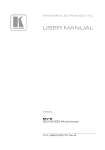
Figure 2 and Table 2 define the rear panel of the MV-6 3G HD-SDI Multiviewer.
Figure 2: MV-6 3G HD-SDI Multiviewer Rear Panel
Table 2: MV-6 3G HD-SDI Multiviewer Rear Panel Features
#
18
19
20
21
22
23
24
25
26
27
8
Feature
INPUTS (1 to 6) and Associated BNC
LOOP Outputs (1 to 6)
RS-232 9-pin D-sub (F) Connector
Mains Power Fuse
Mains Power Switch
SDI BNC Connector
HDMI Connector
OUTPUTS
CV BNC Connector
ETHERNET RJ-45 Connector
RESET Button
Mains Power Connector
Function
Connect Inputs to video sources and Loop outputs to loop video acceptors (see Section 6)
Connect to the serial port on a PC or remote controller (see Section 6.1)
Fuse for protecting the device
Switch for turning the device on or off
Connect to an SDI video acceptor (see Section 7.9)
Connect to an HDMI video acceptor
Connect to a composite video acceptor
Connect to a PC via a LAN for remote control (see Section 6.2)
Press and hold while power cycling the device to reset to factory default configuration (see Section 7.8)
Connect to the mains power
KRAMER: SIMPLE CREATIVE TECHNOLOGY
Installing the MV-6 3G HD-SDI Multiviewer in a Rack
5
Installing the MV-6 3G HD-SDI Multiviewer in a Rack
This section provides instructions for rack mounting the device.
9
Connecting the MV-6 3G HD-SDI Multiviewer
6
Connecting the MV-6 3G HD-SDI Multiviewer
The MV-6 accepts up to six SD/HD/3G HD-SDI inputs. The device outputs
a signal (which can be any combination of the inputs) to the SDI, HDMI
and composite video connectors as shown in Figure 3.
Figure 3: Connecting the MV-6 3G HD-SDI Multiviewer
i
10
Always switch off the power to each device before connecting it to your
MV-6. After connecting your MV-6, connect its power and then switch
on the power to each device.
KRAMER: SIMPLE CREATIVE TECHNOLOGY
Connecting the MV-6 3G HD-SDI Multiviewer
1
To connect the MV-6 3G HD-SDI Multiviewer as shown in Figure 3:
1. Connect up to six SDI sources (SD, HD or 3G HD-SDI) to the INPUT
BNC connectors (for example, 3G HD-SDI cameras to IN 1 and IN 3,
and an SDI player to IN 2).
2. Connect up to six SDI acceptors (SD, HD or 3G HD-SDI) to the
INPUT LOOP BNC connectors (for example, a preview SDI display to
IN 1—LOOP and a non-linear editor to IN 2—LOOP).
3. Connect up to three display acceptors to the OUTPUT connectors (for
example, a 3G HD-SDI display to the OUTPUT SDI BNC connector,
an LCD display to the HDMI connector, and a CV video recorder to
the OUTPUT CV BNC connector).
4. Optional—Connect a PC and/or serial controller to the:
Ethernet connector (see Section 6.2)
—and/or—
RS-232 port2 (see Section 6.1)
5. Connect the power cord 2.
6.1
Connecting to the RS-232 Port
You can connect to the MV-6 via an RS-232 connection using, for example,
a PC. Note that a null-modem adapter/connection is not required.
To connect to the MV-6 via RS-232:
•
Connect the RS-232 9-pin D-sub rear panel port on the MV-6 via a
9-wire straight cable (only pin 2 to pin 2, pin 3 to pin 3, and pin 5 to
pin 5 need to be connected) to the RS-232 9-pin D-sub port on your
PC
6.2
Connecting to the Ethernet Port
You can connect the MV-6 via the Ethernet port in either of the following
ways:
•
For direct connection to the PC, use a crossover cable (see
Section 6.2.1)
•
For connection via a network hub or network router, use a straightthrough cable (see Section 6.2.2)
6.2.1 Connecting the Ethernet Port Directly to a PC
You can connect the Ethernet port of the MV-6 to the Ethernet port on your
PC, via a crossover cable with RJ-45 connectors.
1 Switch off the power to each device before connecting it to your MV-6. After connecting your MV-6, switch on its power
and then switch on the power to each device
2 Not shown in the illustration
11
Connecting the MV-6 3G HD-SDI Multiviewer
This type of connection is recommended for identification of the factory
default IP address 1 of the MV-6 during the initial configuration
After connecting the Ethernet port, configure your PC as follows:
1. Right-click the My Network Places icon on your desktop.
2. Select Properties.
3. Right-click Local Area Connection Properties.
4. Select Properties.
The Local Area Connection Properties window appears.
5. Select the Internet Protocol (TCP/IP) and click the Properties Button
(see Figure 4).
Figure 4: Local Area Connection Properties Window
6. Select Use the following IP Address, and fill in the details as shown in
Figure 5. You can use any IP address in the range 192.168.1.1 to
192.168.1.255 (excluding 192.168.1.39) that is provided by your IT
department.
7. Click OK.
1 The default IP address is 192.168.1.39
12
KRAMER: SIMPLE CREATIVE TECHNOLOGY
Operating the MV-6 3G HD-SDI Multiviewer Locally
Figure 5: Internet Protocol (TCP/IP) Properties Window
6.2.2 Connecting the Ethernet Port via a Network Hub
You can connect the Ethernet port of the MV-6 to the Ethernet port on a
network hub or network router, via a straight-through cable with RJ-45
connectors.
7
Operating the MV-6 3G HD-SDI Multiviewer Locally
The MV-6 sports an LCD video preview screen on which the live video
output is shown. Changes made to the device configuration are reflected
immediately on the screen allowing you to monitor the output in real-time.
The MV-6 is operated locally using the front panel buttons.
7.1
Display
When the MV-6 is powered on, the following is displayed briefly:
MV6 Multiviewer
KRAMER
The device then performs a self test. If the test is successful the
Window/Input list is displayed, an example of which is shown below.
WIN A B C D E F
INP 2 4 5 6 1 3
During operation, if there is no button activity for approximately 60 seconds
the display reverts to the Window/Input list.
13
Operating the MV-6 3G HD-SDI Multiviewer Locally
7.2
Adjusting the Size of a Window
The horizontal and vertical size of each window can be modified.
To adjust the size of a window:
1. Select the required window by pressing one of the Window buttons.
The relevant button lights.
2. Press either the H Size or V Size button to adjust the width or height of
the selected window.
3. Use the left (◄) and right (►) buttons to adjust the window width, and
use the up (▲) and down button (▼) to adjust the window height.
The size changes in real-time.
4. Press Menu twice to exit the window size setting.
7.3
Adjusting the Position of a Window
The horizontal and vertical position of each window can be modified.
To adjust the position of a window:
1. Select the required window by pressing one of the Window buttons.
The relevant button lights.
2. Press either the H Position or V Position button to move the window.
3. Use the left (◄) and right (►) buttons to move the window
horizontally, and use the up (▲) and down button (▼) to move the
window vertically.
The position changes in real-time.
4. Press Menu twice to exit the window position setting.
7.4
Defining and Saving a Custom Window Layout
In addition to the four predefined window layouts, the MV-6 can store two
custom window layouts. Once you have defined a custom window layout
you can save it for future recall.
To define and save a custom, user-defined window layout:
1. Using the Size and Position buttons, adjust all windows to the required
configuration.
2. Press and hold either the U1 or U2 Layout button until the button
flashes once.
The window layout is stored in the respective memory.
7.5
Recalling a Window Layout
You can select any of the four predefined or two custom window layouts
using the window layout buttons.
14
KRAMER: SIMPLE CREATIVE TECHNOLOGY
Operating the MV-6 3G HD-SDI Multiviewer Locally
To select a window layout:
•
Press one of the six screen layout buttons.
The button flashes quickly three times and the window layout is
recalled from the memory
7.6
Freezing/Releasing a Video Output
To freeze/release a video output:
1. Select the required window to freeze.
2. Press the Freeze button (see FREEZE Button).
The button lights and the output video freezes.
3. Press the Freeze button.
The button no longer lights and the video is no longer frozen.
7.7
Locking the Front Panel
Lock the front panel buttons to prevent unwanted key presses from
changing the current configuration.
To lock the front panel:
• Press and hold the Panel Lock button (see PANEL LOCK Button).
The button lights and the front panel buttons are locked. Pressing
any button causes the Locked message to display and the Lock
button to flash
To unlock the front panel:
• Press and hold the Panel Lock button (see PANEL LOCK Button).
The button no longer lights and the front panel buttons are
unlocked
7.8
Resetting the Device to Factory Defaults
To reset the device to the factory defaults:
1. Turn the device off.
2. Press and hold the Reset button on the rear panel of the device.
3. While holding the button depressed, turn the device on.
4. Hold the button depressed for 10 seconds and release the button.
The configuration is reset to the factory default.
7.9
Using the Menu
The menu is displayed on the character display when the Enter button is
pressed. After no button activity for about a minute, the window input list is
displayed but the menu remains open in the background at the same position
it was last left in.
Navigation through the menu is performed as follows:
15
Operating the MV-6 3G HD-SDI Multiviewer Locally
•
Enter—display the menu or select a parameter/value
•
Up (▲)—scroll up through the parameter/value list
•
Down (▼)—scroll down through the parameter/value list
•
Left (◄)—move left in the current field
•
Right (►)—move right through the current field
•
Menu—Move up one level in the menu hierarchy
The main menu comprises six sections:
• Windows (see Section 7.9.1)
• Output (see Section 7.9.2)
• Status (see Section 7.9.3)
• Comm Settings (see Section 7.9.4)
• User Presets (see Section 7.9.5)
• System (see Section 7.9.6)
7.9.1 Windows Sub-menu
The parameters in the Windows sub-menu set the window inputs and
characteristics.
Table 3: Windows Sub-menu Parameters and Descriptions
Parameter
Select window
Description
Selects the window to adjust
Visibility
Makes the selected window visible or non-visible
Select layer
Selects a source to display in the selected window
Input
Selects an input
Size
Position
Freeze
16
Hor size(%)
Sets the horizontal size for the selected window
Ver size(%)
Sets the vertical size for the selected window
X origin(%)
Sets the X origin for the selected window
Y origin(%)
Sets the Y origin for the selected window
Freezes or releases the video
Values
A, B, C, D, E, F
Default—F
Visible, Non-Visible
Default—Visible
TOP, 2, 3, 4, 5, 6
Default—TOP
1, 2, 3, 4, 5, 6
Default—1
1 to 100
Default— 66
1 to 100
Default— 66
0 to 99
Default— 0
0 to 99
Default— 0
ON, OFF
Default—OFF
KRAMER: SIMPLE CREATIVE TECHNOLOGY
Operating the MV-6 3G HD-SDI Multiviewer Locally
7.9.2 Output Sub-menu
The parameters in the Output sub-menu set the output and LCD preview
screen characteristics.
Note: NTSC or PAL is automatically selected depending on the selected
output resolution refresh rate.
Table 4: Output Sub-menu Parameters and Descriptions
Parameter
RESOLUTION
Description
Sets the output resolution
Values
720p59.94, 720p60, 720p50,
1080p59.94, 1080p60, 1080p50
Default— 720p59.94
Turns on and off and sets the source of the NO GENLOCK, INPUT 1, INPUT 2,
unlock signal
INPUT 3, INPUT 4, INPUT 5, INPUT 6
Default—NO GENLOCK
Sets the background color using R, G and 000 to 255
B values
Default—R=1, G=101, B=53
Turns the window border on or off
ON, OFF
Default—ON
Turns the window text labels on and off
ON, OFF
Default—ON
GENLOCK MODE
BACKGROUND >
WIN BORDER
WIN TEXT
7.9.3 Status Sub-menu
The parameters in the Status sub-menu display the input states.
Table 5: Status Sub-menu Parameters and Descriptions
Parameter
INPUTS >
Description
Displays the input states
GENLOCK unlocked
Displays the Genlock state
Values
IN 1 unlocked, IN 2 unlocked, IN 3 unlocked,
IN 4 unlocked, IN 5 unlocked, IN 6 unlocked
7.9.4 Comm Settings Sub-menu
The parameters in the Comm Settings sub-menu set the network IP and
serial communications values.
Table 6: Comm Settings Parameters and Descriptions
Parameter
NETWORK
IP address
RS-232
Description
Sets the IP network address
IP mask
Sets the IP network mask
IP gateway
Sets the IP gateway address
IP port
Sets the IP port number
Baud
Parity
Displays the baud rate
Displays the parity setting
Options
All valid IP addresses
Default—192.168.001.039
All valid subnets
Default—255.255.000.000
All valid gateway addresses
Default—000.000.000.000
All valid TCP ports
Default—05000
115200
none
17
Operating the MV-6 3G HD-SDI Multiviewer Locally
7.9.5 User Presets Sub-menu
The options in the User Presets sub-menu save and recall the preset
configuration memories (see Section 7.4).
Table 7: User Presets Parameters and Descriptions
Parameter
SAVE
Description
Saves the current screen layout as a user
defined layout
LOAD
Loads the selected user defined screen layout
Options
USER PRESET 1, USER PRESET 2
Default—USER PRESET 1
USER PRESET 1, USER PRESET 2
Default—USER PRESET 1
7.9.6 System Sub-menu
The parameters in the System sub-menu display the device versions and set
the video screen characteristics.
Table 8: System Sub-menu Parameters and Descriptions
Parameter
FIRMWARE
FPGA VER
S/N
LCD
Description
The device firmware version
The device FPGA version
The device serial number
Back Light
Brightness
18
Options
AUTO, ON
Default—AUTO
0 to 100
Default—100
KRAMER: SIMPLE CREATIVE TECHNOLOGY
Operating the MV-6 3G HD-SDI Multiviewer Remotely
8
Operating the MV-6 3G HD-SDI Multiviewer Remotely
The MV-6 can be operated remotely using the Kramer MV-6 Controller
software 1 via the:
•
RS-232 serial port (see Section 8.1)
•
Ethernet port (see Section 8.2)
8.1
Operating the MV-6 via the RS-232 Serial Port
Kramer offers free control software that allows you to operate the MV-6
remotely via a PC or serial controller using serial commands (see
Section 12.1). This software can be downloaded from
www.kramerelectronics.com.
8.2
MV-6 Controller Software
For details regarding connecting to the Ethernet port on the MV-6, see
Section 6.2.
The Controller software requires the following:
•
Windows™ XP, Vista or Windows™ 7
•
Microsoft .Net Framework version 3.5
To install the Controller software, download the software and run the setup
file. After installation, running the Controller software for the first time
displays a window similar to that shown in Figure 6.
1 The free MV-6 Control software can be downloaded from http://www.kramerelectronics.com
19
Operating the MV-6 3G HD-SDI Multiviewer Remotely
Figure 6: MV-6 Controller Software Main Window
Table 9: MV-6 Controller Software Features
#
Feature
1
Menu Bar
2
Quick Access Toolbar
3
Windows Position
4
Layer Order
5
Status Indicator
6
7
Switch Windows
Switch Inputs
Function
Operate and configure the device using the Menu Bar options (see
Section 8.2.1)
Operate and configure the device using the quick access toolbar
buttons (see Section 8.2.2)
Modify window size and position by dragging and dropping
individual windows (see Section 8.2.4)
Click and drag individual layers to arrange the layer order (see
Section 8.2.5)
Indicates whether or not the Controller software is connected to the
device (see Section 8.2.5)
Press to select a window (see Section 8.2.5)
Press to select an inputs (see Section 8.2.5)
Note: Unless the device is in off-line mode (by pressing the Take button),
when a change is made on the device (for example, a different output is
selected), the change is reflected almost immediately in the main window of
the Controller Software. Similarly, if a change is made in the Controller
Software, the change is reflected almost immediately on the device.
20
KRAMER: SIMPLE CREATIVE TECHNOLOGY
Operating the MV-6 3G HD-SDI Multiviewer Remotely
8.2.1 The Menu Bar
The menu bar options are shown in Table 10.
Table 10: Menu Bar Options
Menu Bar Options
Sub Menu
FILE
Open
Save
Exit
DEVICE
Connect/Disconnect
DISPLAY
ABOUT
Description
Open an existing configuration
Save the current configuration
Exit the MV-6 Controller software
Connect or disconnect to the device (see Section 8.2.3)
Press Take to put the device in off-line mode. Press
Update to implement waiting changes and return the
Take/Update
device to on-line mode (see Section 8.2.5)
Firmware Update
Update the device firmware (see Section 8.2.12)
Retrieve and display the device details, such as, model,
Device Details
unit name, version, and so on. (see Section 8.2.5)
Set the screen to display one of the preconfigured
configurations:
Presets
6-Split, Quad, Full, 2-Split
Set the output resolution:
Output Resolution
720P 59.94Hz, 720P 50Hz, 1080P 60Hz, 720P 60Hz,
1080P 59.94Hz, 1080P 50Hz
Unlocks the genlock or sets the source for genlock control:
Genlock Control
Free Run (default), Input 1, Input 2, Input 3, Input 4, Input
5, Input 6
Background Color
Sets the background color of the window
Window Border
Turns the window border on and off
Refresh
Retrieves full information from the device
Displays the Step-in Software and Kramer company details
Note: Any actions that you are not authorized to perform are grayed out.
8.2.2 The Quick Access Toolbar
The Quick Access Toolbar buttons are shown in Figure 7 and described in
Table 10.
Figure 7: Quick Access Toolbar
Table 11: Quick Access Toolbar Options
Feature
Description
Open an existing project
Save the current project
Connects to and disconnects from the device (see
Section 8.2.3)
21
Operating the MV-6 3G HD-SDI Multiviewer Remotely
Feature
Description
Press Take to enable multiple off-line changes to be made.
Press Update to implement the changes (see Section 8.2.8)
Set the screen to display the 6-window configuration
Set the screen to display the 4-window configuration
Set the screen to display the single-window configuration
Set the screen to display the 2-window configuration
Freezes the output video
Sets the visibility of the active window
8.2.3 Connecting to the Device
To connect to the device:
1. Click the Connect button.
The window shown in Figure 8 appears.
Figure 8: Connect Window
2. Select the required method of connection radio button:
•
For Ethernet, enter the IP address and Port number of the device. To
set the default IP address and Port number, press the Default button.
22
KRAMER: SIMPLE CREATIVE TECHNOLOGY
Operating the MV-6 3G HD-SDI Multiviewer Remotely
•
For a serial connection, select the required Com port from the dropdown list.
3. Click Connect.
If the connection is successful, the main window shown in Figure 6
appears. If the connection is not successful, a Timeout error message
appears.
8.2.4 Windows Position
The windows can be manually manipulated in size and position in the
Window Position area.
Figure 9: Windows Position
To change the size of a window:
•
Click, hold and drag the required window handle
To change the position of a window:
•
Click, hold and drag anywhere in the window
23
Operating the MV-6 3G HD-SDI Multiviewer Remotely
8.2.5 Switch Buttons
The switching configuration can be modified by clicking on the Windows
and Inputs buttons.
Figure 10: Switch Buttons
Table 12: Switch Button Characteristics
#
1
2
3
4
5
6
7
8
8.2.6
C Window
Windows Buttons (A to F)
Camera
Layer 4
4
Inputs Buttons (1 to 6)
Camera
Input icon
Description
Window identifier (A to F)
Press to select a window to assign to an input (see Section 8.2.9)
The label of the input assigned to this window (see Section 8.2.9)
The layer (Top layer to 6) of this window (see Section 8.2.7)
Input number (1 to 6)
Press to select an input to assign to a window (see Section 8.2.9)
Input button label (see Section 8.2.9)
User assigned icon for this input (see Section 8.2.9)
Connection Status
The connection status can be one of the following states:
•
Online—the device is connected and being updated in real-time by the
software
•
Online, in take mode (not updating device)—the device is connected
but changes are only implemented when the Update button is pressed
•
Offline—in Take mode
24
KRAMER: SIMPLE CREATIVE TECHNOLOGY
Operating the MV-6 3G HD-SDI Multiviewer Remotely
8.2.7 Changing the Layer Order
You can modify the order in which the windows are arranged. The top layer
is on the right and the bottom layer on the left. In Figure 11 layer A is on
top and layer F is at the bottom.
Figure 11: Layer Order
To change the window layer order:
1. Click and hold on the layer that you want to move.
2. Drag the layer to the right or left into the required position and release.
The layer is placed in the required position.
8.2.8 Implementing Multiple Actions At Once
To implement multiple actions at once:
1. Press the Take button to put the device in off-line mode.
The button changes to the Update button and the device is in off-line
mode.
2. Perform the required actions, such as, switching and layer order
changes.
3. Press the Update button.
The button changes to the Take button and all changes are
implemented.
8.2.9 Switching an Input to a Window
To switch an input to a window:
1. Click on the required window button.
The window is selected and the button changes to a solid color as
shown in Figure 12.
25
Operating the MV-6 3G HD-SDI Multiviewer Remotely
Figure 12: Switching an Input to a Window
2. Click on the required Inputs button.
The input is assigned to the previously selected window and the button
changes to a solid color.
8.2.10 Changing a Window Setup
To change a window setup:
1. Right-click on the relevant Windows button.
The Window Setup window appears as shown in Figure 13.
Figure 13: Windows Setup Window
2.
3.
4.
5.
6.
7.
26
From the Connect to Input drop-down list, select the required input.
Click the Freeze icon to freeze this window.
Click the Visibility icon to modify the visibility of this window.
In the Position fields, enter the x and y position for the window.
In the Size fields, enter the width and height for the window.
Click OK.
The Window setup is changed.
KRAMER: SIMPLE CREATIVE TECHNOLOGY
Operating the MV-6 3G HD-SDI Multiviewer Remotely
8.2.11 Changing Input Button Properties
To change the properties of an input button:
1. Right-click on the relevant input button.
The Input Properties window appears as shown in Figure 14.
Figure 14: Input Button Properties Window
2. In the Label text box, enter the required button label.
(The label is limited to 10 characters.)
3. Select the required icon from the list or click on the Select icon from
file button and browse to the required file.
4. Modify the Text Overlay properties as required.
5. Click OK.
The input button characteristics are changed.
27
Operating the MV-6 3G HD-SDI Multiviewer Remotely
8.2.12 Changing the Device Details
From this window you can change the device name and its IP
communication parameters.
To change the device details:
1. From the Menu bar, click on Device.
The Device Details window appears as shown in Figure 15.
Figure 15: Device Details Window
2. Modify the parameters as required. For each modified parameter, click
Set Value.
3. Click Close.
Note: If you modify any of the IP parameters you need to reconnect to the
device with the new parameters.
8.2.13 Updating the Firmware
To update the firmware you must be logged in as Admin.
To update the firmware:
1. Download the latest firmware file from
http:www.kramerelectronics.com.
2. Click Unit > Firmware Update.
3. Browse to the firmware file that you downloaded.
28
KRAMER: SIMPLE CREATIVE TECHNOLOGY
Operating the MV-6 3G HD-SDI Multiviewer Remotely
4. Click Open.
The device firmware is loaded.
Note: Do not interrupt the uploading process or the device may be
damaged.
5. When the process is complete, reset the device.
8.2.14 Setting the IP Network Parameters
To set the IP network parameters you must be logged in as Admin.
To set the IP network parameters:
1. Click Unit > Device Details.
2. Under Connectivity, edit the required parameter.
3. Click Set Value.
A confirmation message appears.
4. Click OK.
The parameter is set.
5. Reboot the device.
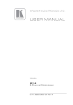
8.2.15 Displaying the MV-6 Software Version Number
To display the MV-6 Software version number:
1. From the Menu bar, click About.
The About MV6 Controller window appears as shown in Figure 16.
Figure 16: About MV-6 Window
2. Click OK to close the window.
29
Upgrading the Firmware
9
Upgrading the Firmware
For instructions on upgrading the firmware see “Upgrading the MV-6
Firmware Using the K-Upload Software”.
Note: To upgrade to firmware V3.2.7321 you must use K-Upload software
V1.0.0.50. After upgrading, perform a factory reset (see Section 7.8).
10 Technical Specifications
Table 13 lists the technical specifications of the MV-6.
Table 13: MV-6 Technical Specifications
INPUTS:
6 SDI serial
video, 75Ω on
BNC connectors
SD
HD
SMPTE-259M
SMPTE-292
1
SMPTE-125M
480i – 59.94
ITU-R BT.656-5
576i – 50
SMPTE-296M
720p – 59.94/60/50
SMPTE-274M
1080i – 59.94/60/50
1080p – 29.97/30/25
23.98/24
23.98sF/24sF
3G
OUTPUTS 2:
MAX. INPUT
LEVEL:
1 HDMI
SMPTE-424M
SMPTE-296M
1080p – 59.94/60/50
800mVpp /75Ω
1 CV on a BNC connector
For 720p @50Hz and 1920p @50Hz the output is PAL
For 720p @59.94/60Hz and 1920p @59.94/60Hz the output is NTSC
1 SDI output, 75Ω on
BNC connector
SMPTE-292
SMPTE-296M
720p – 59.94/60/50
SMPTE-424M
SMPTE-296M
1080p – 59.94/60/50
MAX. OUTPUT LEVEL:
800mVpp /75Ω
6 LOOP
PREVIEW SCREEN:
SERIAL BIT DATA
RATE:
CONTROLS:
POWER
CONSUMPTION:
OPERATING
TEMPERATURE:
STORAGE
TEMPERATURE:
HUMIDITY:
DIMENSIONS:
WEIGHT:
ACCESSORIES:
4.3” TFT color LCD panel
Up to 2.97Gbps
Front-panel, RS-232, Ethernet
Universal, 100-240V AC, 50/60Hz 35VA
0° to +40°C (32° to 104°F)
–40° to +70°C (–40° to 158°F)
10% to 90%, RHL non-condensing
19" x 7.4" x 2U (W, D, H) rack mountable
3.1kg (6.83lbs) approx.
Power cord, Rack “ears”
1 Specifications are subject to change without notice
2 The device does not pass audio
30
KRAMER: SIMPLE CREATIVE TECHNOLOGY
Default Communication Parameters
11 Default Communication Parameters
Table 14: Default Communication Parameters
RS-232
Protocol 3000
Baud Rate:
Data Bits:
Stop Bits:
Parity:
Command Format:
Example (Output 1 to Input 2):
115200
8
1
None
ASCII
#V 2>1CR
Ethernet
To reset the IP settings to the factory reset values, power cycle the device while
holding in the Factory Reset button, located on the rear panel of the unit
IP Address:
192.168.1.39
Subnet mask:
255.255.255.0
Default gateway:
192.168.1.1
TCP Port #: 5000
5000
UDP Port #: 50000
50000
Maximum UDP Ports:
10
Maximum TCP Ports:
4
31
Kramer Protocol 3000
12 Kramer Protocol 3000
The MV-6 can be operated using serial commands from a PC, remote
controller or touch screen using the Kramer Protocol 3000.
This section describes:
• Kramer Protocol 3000 syntax (see Section 12.1)
• Kramer Protocol 3000 commands (see Section 12.2)
12.1 Kramer Protocol 3000 Syntax
12.1.1 Host Message Format
Start
Address (optional)
Body
Delimiter
#
device_id@
Message
CR
12.1.1.1 Simple Command
Command string with only one command without addressing:
Start
Body
Delimiter
#
Command SP Parameter_1,Parameter_2,…
CR
12.1.1.2 Command String
Formal syntax with commands concatenation and addressing:
Start
Address
Body
Delimiter
#
device_id@
Command_1 Parameter1_1,Parameter1_2,…|
Command_2 Parameter2_1,Parameter2_2,…|
Command_3 Parameter3_1,Parameter3_2,…|…
CR
12.1.2 Device Message Format
Start
~
Address (optional)
device_id@
Body
Message
delimiter
CR LF
12.1.2.1 Device Long Response
Echoing command:
Start
Address (optional)
Body
Delimiter
~
device_id@
Command SP [Param1 ,Param2 …] result
CR LF
CR = Carriage return (ASCII 13 = 0x0D)
LF = Line feed (ASCII 10 = 0x0A)
SP = Space (ASCII 32 = 0x20)
12.1.3 Command Terms
Command
A sequence of ASCII letters ('A'-'Z', 'a'-'z' and '-').
Command and parameters must be separated by at least one space.
32
KRAMER: SIMPLE CREATIVE TECHNOLOGY
Kramer Protocol 3000
Parameters
A sequence of alphanumeric ASCII characters ('0'-'9','A'-'Z','a'-'z' and some
special characters for specific commands). Parameters are separated by
commas.
Message string
Every command entered as part of a message string begins with a message
starting character and ends with a message closing character.
Note: A string can contain more than one command. Commands are
separated by a pipe ( '|' ) character.
Message starting character
'#' – For host command/query
'~' – For device response
Device ID (Optional, for K-NET)
K-NET Device ID followed by '@'
Query sign
'?' follows some commands to define a query request.
Message closing character
CR – For host messages; carriage return (ASCII 13)
CRLF – For device messages; carriage return (ASCII 13) + line-feed (ASCII
10)
Command chain separator character
When a message string contains more than one command, a pipe ( '|' )
character separates each command.
Spaces between parameters or command terms are ignored.
12.1.4 Entering Commands
You can directly enter all commands using a terminal with ASCII
communications software, such as HyperTerminal, Hercules, etc. Connect
the terminal to the serial or Ethernet port on the Kramer device. To enter CR
press the Enter key.
( LF is also sent but is ignored by command parser).
For commands sent from some non-Kramer controllers like Crestron, some
characters require special coding (such as, /X##). Refer to the controller
manual.
12.1.5 Command Forms
Some commands have short name syntax in addition to long name syntax to
allow faster typing. The response is always in long syntax.
33
Kramer Protocol 3000
12.1.6 Chaining Commands
Multiple commands can be chained in the same string. Each command is
delimited by a pipe character (“|”). When chaining commands, enter the
message starting character and the message closing character only once,
at the beginning of the string and at the end.
Commands in the string do not execute until the closing character is
entered.
A separate response is sent for every command in the chain.
12.1.7 Maximum String Length
64 characters
12.2 Kramer Protocol 3000 Commands
12.2.1 Common Commands
Command
Abbreviation
Description
Type
Protocol handshaking
BUILD-DATE?
Read device build date
Common-mandatory
End User
FACTORY
Reset to factory default
configuration
Common
End User
HELP
Common-mandatory
Permission
#
End User
List of commands
Common-mandatory
End User
LOCK-FP
LCK
Lock front panel
Common
Administrator
LOCK-FP?
LCK?
GET Lock front panel
Common
End User
MACH-NUM
Set Machine number
Common
Administrator
MODEL?
Read device model
Common-mandatory
End User
NAME
Set machine (DNS) name
Common
Administrator
NAME?
Query machine (DNS) name
Common
End User
NAME-RST
Reset machine name to factory
default (DNS)
Common
Administrator
PROT-VER?
Read device protocol version
Common-mandatory
End User
PRST-RCL
Read saved preset list (see Note
below)
Common
End User
RESET
Reset device
Common-mandatory
Administrator
SN?
Read device serial number
Common-mandatory
End User
UPGRADE
Execute firmware upgrade
Common
Administrator
VERSION?
Read device firmware version
Common-mandatory
End User
Note: The first four presets are geometrical presets (only the size and
position of the windows are affected), but presets five and six include
additional information.
34
KRAMER: SIMPLE CREATIVE TECHNOLOGY
Kramer Protocol 3000
12.2.2 Network Setting Commands
Command
ETH-PORT
Abbreviation
ETHP
Description
Type
Change protocol Ethernet port Ethernet
Permission
Administrator
ETH-PORT?
ETHP?
Query protocol Ethernet port
Ethernet
End User
NET-DHCP
NTDH
Set DHCP mode
Ethernet
Administrator
NET-DHCP?
NTDH?
Query DHCP mode
Ethernet
End User
NET-GATE
NTGT
Set Gateway
Ethernet
Administrator
NET-GATE?
NTGT?
Query Gateway
Ethernet
End User
NET-IP
NTIP
Set IP address
Ethernet
Administrator
NET-IP?
NTIP?
Query IP address
Ethernet
End User
NET-MAC?
NTMC?
Query MAC address
Ethernet
End User
NET-MASK
NTMSK
Set subnet mask
Ethernet
Administrator
NET-MASK?
NTMSK?
Query subnet mask
Ethernet
End User
12.2.3 Device Specific Commands
Command
Description
Syntax
Response
BCKGRND
Set background
color
#BCKGRND R, G, B<CR>
~BCKGRND R,G,B [result]<CR>
BCKGRND?
Get background
color
#BCKGRND ?
~BCKGRND? R,G,B <CR>
CRDT
Set window size
and position in
pixels
#CRDT win_num,x0,y0,x1,y1<CR>
~CRDT
win_num,x0,y0,x1,y1[result]<CR>
CRDT?
Get window size
and position in
pixels
#CRDT? win_num<CR>
~CRDT? win_num,x0,y0,x1,y1<CR>
ETH-PORT
Set IP port
#ETH-PORT <protocol>,<port_num> ~ETH-PORT <protocol>, <port_num>
<CR>
[result] <CR>
ETH-PORT?
Get IP port
#ETH-PORT? <protocol>
~ETH-PORT <protocol>, <port_num>
<CR>
FPGA-VER?
Get FPGA
version
#FPGA-VER? <id><CR>
~FPGA-VER <id>,<expected
ver>,<actual ver>
GNLCK
Set genlcock
#GNLCK id <CR>
~GNLCK id [result]<CR>
GNLCK?
Get genlcock
#GNLCK? id<CR>
~GNLCK? id, state<CR>
NTGT
Set gateway
address
#NTGT <gateway> <CR>
~NTGT <gateway> [result]<CR>
NTGT?
Get gateway
address
#NTGT?
~NTGT <gateway> <CR>
NTIP
Set IP address
#NTIP <ip address> <CR>
~NTIP <ip address> [result]<CR>
NTIP?
Get IP address
#NTIP?
~NTIP <ip address> <CR>
NTMSK
Set IP mask
#NTMSK <ip mask> <CR>
~NTMSK <ip mask> [result]<CR>
NTMSK?
Get IP address
#NTMSK?
~NTMSK <ip mask> <CR>
OVRBLK
Set text overlay
background
parameters
(color,
transparency)
#OVRLBK stage,stage_id,r,g,b,alpha ~ nn@OVRLBK stage,stage_id,r,g,b,
alpha
35
Kramer Protocol 3000
Command
Description
Syntax
Response
OVRBLK?
Get text overlay
background
parameters
(color,
transparency)
#OVRLBK? stage,stage_id
~ nn@OVRLBK stage,stage_id,r,g,b,
alpha
OVRL
Set text overlay
parameters
(mode, color
(RGB),
transparency)
#OVRL stage, stage_id,mode,r,g, b,
alpha
~ nn@OVRL stage,stage_id,mode,r,g,
b,alpha
OVRL?
Get text overlay
parameters
(mode, color
(RGB),
transparency)
#OVRL? stage,stage_id
~ nn@OVRL stage,stage_id,mode,r,g,
b,alpha
OVRLTXT
Set overlay text
#OVRLTXT stage, stage_id, type,
size,x,y,string
~ nn@OVRLTXT stage, stage_id,
type,size,x,y,string
OVRLTXT?
Get overlay text
#OVRLTXT? stage, stage_id
~ nn@OVRLTXT stage, stage_id,
type,size,x,y,string
SN?
Get serial
number
SRC-BLANK
Set window
visibility
#SRC-BLANK win_num,enable<CR> ~SRC-BLANK win_num,enable
[result]<CR>
#SRC-BLANK *, enable<CR>
~SRC-BLANK *,enable [result]<CR>
SRC-BLNK?
Get window
visibility
#SRC-BLANK? win_num<CR>
#SRC-BLANK? *<CR>
SRC-VID
Set window input #SRC-VID win_num,in_num<CR>
SRC-VID?
Get window input # SRC-VID? win_num<CR>
~SRC-VID? win_num, in_num <CR>
VERSION?
Get firmware
version
~VERSION <firmware version><CR>
VID-RES
Set output/input
resolution
#VID-RES IN/OUT, id, HSIZE,
VSIZE, ”I”/”P”, FramRate <CR>
~VID-RES IN/OUT, id, HSIZE, VSIZE,
”I”/”P”, FramRate [result] <CR>
VID-RES?
Get output/input
resolution
#VID-RES? IN/OUT, id<CR>
~VID-RES? IN/OUT, id, HSIZE,
VSIZE, ”I”/”P”, FramRate <CR>
WIN
Set active
window
#WIN win_num<CR>
~WIN win_num [result]<CR>
WIN?
Get active
window
#WIN? >CR>
~WIN? win_num<CR>
WND-FRZ
Set freeze
window
#WND-FRZ win_num,freeze <CR>
~WND-FRZ win_num,freeze [result]
<CR>
WND-FRZ?
Get freeze
window
#WND-FRZ? win_num<CR>
~WND-FRZ? win_num,freeze<CR>
WND-LR
Set window layer #WND-LR win_num,layer <CR>
~WND-LR win_num,layer [result]<CR>
WND-LR?
Get window layer #WND-LR? win_num<CR>
~WND-LR? win_num, layer<CR>
36
~SN <device serial number> <CR>
~SRC-BLANK? win_num, enable<CR>
~SRC-BLANK? *, enable<CR>
~SRC-VID win_num,in_num
[result]<CR>
KRAMER: SIMPLE CREATIVE TECHNOLOGY
For the latest information on our products and a list of
Kramer distributors visit www.kramerelectronics.com
where updates to this user manual may be found.
We welcome your questions, comments and feedback.
Safety Warning:
Disconnect the device from the power supply before
opening/servicing.
Caution
P/N: 2900- 000737
Rev: 6
Kramer Electronics, Ltd.
Web site: www.kramerelectronics.com
E-mail: [email protected]
P/N: 2900-000737 REV 6