1
K R A ME R E LE CT R O N IC S L T D .
USER MANUAL
MODEL:
FC-340
SDI Scaler/Embedder/Scan
Converter
P/N: 2900-000768 Rev 3
Contents
1
Introduction
1
2
2.1
2.2
2.3
3
Getting Started
Achieving the Best Performance
Safety Instructions
Recycling Kramer Products
Overview
2
2
2
3
4
4
Defining the FC-340 SDI Scaler/Embedder/Scan Converter
5
5
Installing the FC-340 in a Rack
6
6.1
6.2
6.3
7
7.1
7.2
7.3
7.4
7.5
Connecting the FC-340
Connecting a Serial Controller to the FC-340
Connecting to the FC-340 via Ethernet
Connecting the Balanced/Unbalanced Stereo Audio Output
Operating the FC-340
Changing the Output Resolution
Using the Menu
Resetting the Device to Factory Default Configuration
Locking and Unlocking the Front Panel
Updating the Firmware Using the K-Upload Software
8
Technical Specifications
18
9
9.1
Default Parameters
Default Communication Parameters
19
19
10
10.1
10.2
10.3
Kramer Protocol
Protocol 3000 Syntax
Command Part Details
Kramer Protocol 3000 Commands
20
20
21
22
7
8
9
9
12
13
13
14
16
17
17
Figures
Figure 1: FC-340 SDI Scaler/Embedder/Scan Converter Front Panel
Figure 2: FC-340 SDI Scaler/Embedder/Scan Converter Rear Panel
Figure 3: Connecting the FC-340 SDI Scaler/Embedder/Scan Converter
Figure 4: Local Area Connection Properties Window
Figure 5: Internet Protocol (TCP/IP) Properties Window
Figure 6: Balanced Stereo Audio Connection
Figure 7: Unbalanced Stereo Audio Connection
FC-340 – Contents
5
6
8
10
11
12
12
i
1
Introduction
Welcome to Kramer Electronics! Since 1981, Kramer Electronics has been
providing a world of unique, creative, and affordable solutions to the vast range of
problems that confront the video, audio, presentation, and broadcasting
professional on a daily basis. In recent years, we have redesigned and upgraded
most of our line, making the best even better!
Our 1,000-plus different models now appear in 11 groups that are clearly defined
by function: GROUP 1: Distribution Amplifiers; GROUP 2: Switchers and Routers;
GROUP 3: Control Systems; GROUP 4: Format/Standards Converters; GROUP
5: Range Extenders and Repeaters; GROUP 6: Specialty AV Products; GROUP
7: Scan Converters and Scalers; GROUP 8: Cables and Connectors; GROUP 9:
Room Connectivity; GROUP 10: Accessories and Rack Adapters and GROUP 11:
Sierra Products.
Congratulations on purchasing your FC-340 SDI Scaler/Embedder/Scan
Converter which is ideal for broadcast and production studios as well as digital
and analog AV authoring.
FC-340 - Introduction
1
2
Getting Started
We recommend that you:
•
Unpack the equipment carefully and save the original box and packaging
materials for possible future shipment
•
i
2.1
Review the contents of this user manual
Go to http://www.kramerelectronics.com to check for up-to-date
user manuals, application programs and to check whether firmware
upgrades are available (where appropriate).
Achieving the Best Performance
To achieve the best performance:
•
Use only good quality connection cables (we recommend Kramer highperformance, high-resolution cables) to avoid interference, deterioration in
signal quality due to poor matching, and elevated noise levels (often
associated with low quality cables)
•
•
Do not secure the cables in tight bundles or roll the slack into tight coils
Avoid interference from neighboring electrical appliances that may adversely
influence signal quality
•
Position your Kramer FC-340 away from moisture, excessive sunlight and
dust
!
2.2
Safety Instructions
!
2
This equipment is to be used only inside a building. It may only be
connected to other equipment that is installed inside a building.
Caution:
No operator serviceable parts inside the unit
Warning:
Use only the Kramer Electronics input power wall
adapter that is provided with the unit.
Warning:
Disconnect the power and unplug the unit from the wall
before installing
FC-340 - Getting Started
2.3
Recycling Kramer Products
The Waste Electrical and Electronic Equipment (WEEE) Directive 2002/96/EC
aims to reduce the amount of WEEE sent for disposal to landfill or incineration by
requiring it to be collected and recycled. To comply with the WEEE Directive,
Kramer Electronics has made arrangements with the European Advanced
Recycling Network (EARN) and will cover any costs of treatment, recycling and
recovery of waste Kramer Electronics branded equipment on arrival at the EARN
facility. For details of Kramer’s recycling arrangements in your particular country
go to our recycling pages at http://www.kramerelectronics.com/support/recycling/.
FC-340 - Getting Started
3
3
Overview
The FC-340 SDI Scaler/Embedder/Scan Converter is ideal as a broadcast-quality
video scaler and audio embedder/de-embedder for digital signals up to 3G
HD-SDI.
All mentions of SDI in this manual include signals up to and including 3G HD-SDI.
The FC-340 features:
•
A maximum data rate of 3Gpbs
•
1 SDI video input and 2 SDI video outputs
•
1 re-clocked, looping video output
•
1 composite video output
•
1 balanced audio output
•
2 AES/EBU audio inputs and 2 AES/EBU audio outputs
•
The option to select either the embedded audio or to embed two
independent audio groups
•
Kramer reKlocking™ & Equalization Technology that rebuilds the digital
signal to travel longer distances
•
4
An LCD text display for easy configuration and operation
FC-340 - Overview
5
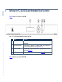
4
Defining the FC-340 SDI Scaler/Embedder/Scan Converter
Figure 1 defines the front panel of the FC-340.
Figure 1: FC-340 SDI Scaler/Embedder/Scan Converter Front Panel
FC-340 – Defining the FC-340 Presentation Switcher
#
Feature
Function
1
LCD Readout
Displays either the input/output resolution currently selected or the menu during
configuration
2
Menu Navigation Buttons
Press the Enter, up (▲), down (▼), left (◄) and right (►) buttons to navigate the
menu, and modify parameters or values (see Section 7.2)
3
PANEL LOCK Button
Press and hold to lock the front panel buttons. Press and hold again to unlock the
buttons (see Section 7.4)
4
ESC Button
Press to move back one level through the menu (see Section 7.2)
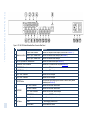
Figure 2 defines the rear panel of the FC-340.
FC-340 – Defining the FC-340 Presentation Switcher
Figure 2: FC-340 SDI Scaler/Embedder/Scan Converter Rear Panel
#
Feature
1
2
ANALOG OUTPUT
3
Function
CV BNC Video Connector
Connect to a composite video acceptor (see the Note in Section 7.1)
Audio 1 5-pin Terminal Block
Connect to a balanced audio acceptor (see Section 6)
Audio 2 5-pin Terminal Block
Connect to a balanced audio acceptor
4
RS-232 3-pin Serial Port Terminal Block
5
ETHERNET RJ-45 Connector
Connect to a PC controller via a LAN (see Section 6.2)
6
IN SDI BNC Connector
Connect to an SDI signal source
7
LOOP BNC Connector
Connect to an SDI acceptor
8
OUT 1 BNC Connector
Connect to an SDI acceptor
9
OUT 2 BNC Connector
Connect to an SDI acceptor
RESET Button
Press and hold while switching on the device to reset to factory default
parameters (see Section 9)
10
Connect to a serial controller (see Section 6.1)
11
IN 1 BNC Connector
Connect to an AES/EBU audio source
12
IN 2 BNC Connector
Connect to an AES/EBU audio source
OUT 1 BNC Connector
Connect to an AES/EBU audio acceptor
14
OUT 2 BNC Connector
Connect to an AES/EBU audio acceptor
15
Power Socket
Connect the mains power cord
Fuse
AC mains supply protection fuse
Power Switch
Turns the device on and off
13
16
6
17
AES/EBU
AC Mains
5
Installing the FC-340 in a Rack
FC-340 - Installing the FC-340 in a Rack
7
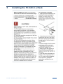
6
Connecting the FC-340
i
Switch off the power to all devices before connecting them to your
FC-340. After connecting your FC-340, connect its power and then
switch on the power to the other devices.
Figure 3: Connecting the FC-340 SDI Scaler/Embedder/Scan Converter
To connect the FC-340 as illustrated in the example in Figure 3:
1. Connect an SD/HD/3G HD-SDI source (for example, an HD digital video
camera) to the SDI IN BNC connector.
2. Connect the SDI OUT 1 BNC connector to an SDI acceptor (for example, an
SDI display).
8
FC-340 - Connecting the FC-340
3. Connect the SDI OUT 2 BNC connector to an SDI acceptor (for example, an
SDI display).
4. Connect the CV ANALOG OUTPUT BNC connector to a composite video
acceptor (for example, a composite video recorder). See the Note in
Section 7.1.
5. Connect the CV 5-pin terminal block to a balanced audio acceptor (for
example, an amplifier).
6. Connect AES digital audio sources (for example, DAT players) to the
AES/EBU IN 1 and IN 2 BNC connectors.
7. Connect the AES/EBU OUT 1 BNC connector to an AES digital audio
acceptor (for example, a DAT recorder).
8. Optional—Connect a controller via either RS-232 or a LAN to the Ethernet
RJ-45 connector.
6.1
Connecting a Serial Controller to the FC-340
You can connect to the FC-340 via an RS-232 connection using, for example, a
PC.
To connect to the FC-340 via RS-232:
•
Connect the 3-pin terminal block on the rear panel port of the FC-340 (pin G
to pin 5, pin Rx to pin 3, pin Tx to pin 2) to the RS 232 9-pin D-sub port on
your PC
6.2
Connecting to the FC-340 via Ethernet
You can connect the FC-340 via Ethernet via either of the following methods:
•
•
A crossover cable (see Section 6.2.1) for direct connection to the PC
A straight through cable (see Section 6.2.2) for connection via a network hub
or network router
After connecting the Ethernet port, you have to install and configure your Ethernet Port. For
detailed instructions, see the Ethernet Configuration Guide (Lantronix) in the technical support
section on our Web site http://www.kramerelectronics.com.
FC-340 - Connecting the FC-340
9
6.2.1
Connecting the Ethernet Port directly to a PC
You can connect the Ethernet port on the FC-340 to the Ethernet port on your PC
via a crossover cable with RJ-45 connectors. This type of connection is
recommended for identification of the factory default IP Address of the FC-340
during the initial configuration.
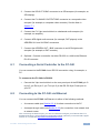
To configure your PC after connecting the Ethernet port:
1. Right-click the My Network Places icon on your desktop.
2. Select Properties.
3. Right-click Local Area Connection Properties.
4. Select Properties.
The Local Area Connection Properties window appears.
5. Select the Internet Protocol (TCP/IP) and click the Properties Button.
Figure 4: Local Area Connection Properties Window
10
FC-340 - Connecting the FC-340
6. Select Use the following IP Address and enter the details as shown in
Figure 5. You can use any IP address in the range 192.168.1.1 to
192.168.1.255 (excluding 192.168.1.39) that is provided by your IT
department.
Figure 5: Internet Protocol (TCP/IP) Properties Window
7. Click OK.
6.2.2
Connecting to the Ethernet Port via a Network Switch/Hub
To connect to the Ethernet port on the FC-340 via a network switch/hub:
•
Connect the PC to the Ethernet network switch/hub using a straight through
cable
FC-340 - Connecting the FC-340
11
6.3
Connecting the Balanced/Unbalanced Stereo Audio
Output
This section illustrates how to wire the devices to the balanced audio output:
•
A balanced stereo output connection, see Figure 6
•
An unbalanced stereo output connection, see Figure 7
Figure 6: Balanced Stereo Audio Connection
Figure 7: Unbalanced Stereo Audio Connection
12
FC-340 - Connecting the FC-340
7
Operating the FC-340
In general operation, the video signal received on the SDI IN connector is output
simultaneously on both SDI OUT connectors as well as the composite video
ANALOG OUTPUT connector. The audio embedded in the SDI input signal is
output on both AES/EBU connectors simultaneously as well as on the balanced
audio ANALOG OUTPUT.
When the FC-340 is powered on, the following is displayed briefly:
FC340
KRAMER
The device then performs a self test. If the test is successful the Menu is displayed
as shown below.
VIDEO OUT
>
AUDIO OUT
>
If there is no button activity for approximately 30 seconds, the display reverts to
displaying the input status and output resolution similar to that shown below:
IN unlocked
OUT 1080p59.94
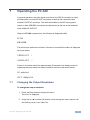
7.1
Changing the Output Resolution
To change the output resolution:
1. Press the Enter button to display the menu.
The menu is displayed.
2. Using the up (▲) or down (▼) button, move through the menu options until
the flashing cursor is on Video Out.
FC-340 - Operating the FC-340
13
3. Press Enter.
The Video Out options are displayed.
4. Using the up (▲) or down (▼) button, move through the Video Out options
until the flashing cursor is on Resolution.
5. Press Enter.
The Resolution options are displayed.
6. Using the up (▲) or down (▼) button, select the required output resolution.
7. Press Enter.
The selected output resolution is saved.
Note: The CV output follows the frame rate of the selected resolution. For 50Hz
resolutions the PAL standard is used, and for 59.94/60Hz resolutions NTSC is used.
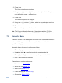
7.2
Using the Menu
The menu is shown on the display when the Enter button is pressed. If there is no
button activity for approximately 30 seconds, the display reverts back to the
Input/Output display.
Navigation through the menu is performed as follows:
•
Enter—display the menu or select a parameter/value
•
Up (▲) or Right (►)—scroll up through the parameter/value list
•
Down (▼) or Left (◄)—scroll down through the parameter/value list
•
ESC—Move to the first level menu
The main menu comprises six sections:
14
•
Video Out (see Section 7.2.1)
•
Audio Out (see Section 7.2.2)
•
Status (see Section 7.2.3)
•
Comm Settings (see Section 7.2.4)
•
System (see Section 7.2.5)
FC-340 - Operating the FC-340
7.2.1
Video Out Sub-menu
The parameters in the Video Out sub-menu set the output video characteristics.
Parameter
Description
Options
Resolution
Sets the output
resolution
Genlock
Mode
Sets the source for
the genlock signal
1080p59.94, 1080p60, 1080p50, NTSC, PAL,
720p59.94, 720p60, 720p50, 1080i59.94,
1080i60, 1080i50
Default—720p/59.94
No Genlock, Input
Default—No Genlock
Note: The CV output frame rate follows the above settings (see Section 7.1)
7.2.2
Audio Out Sub-menu
The parameters in the Audio Out sub-menu set the audio output characteristics.
Parameter
Description
Options
Embedding >
Sets the audio group to
embed Group 1, Group
2, Group 3 and Group 4
Embeds the AES audio
input 1
Off, Embedded input, AES input
Default—Embedded input
AES Out 1
AES Out 2
7.2.3
Embeds the AES audio
input 2
Gr1 Pair1, Gr1 Pair2, Gr2 Pair1, Gr2 Pair2,
Gr3 Pair1, Gr3 Pair2, Gr4 Pair1, Gr4 Pair2,
AES In1, AES In2, Off
Default—Gr1 Pair1
Gr1 Pair1, Gr1 Pair2, Gr2 Pair1, Gr2 Pair2,
Gr3 Pair1, Gr3 Pair2, Gr4 Pair1, Gr4 Pair2,
AES In1, AES In2, Off
Default—Gr1 Pair2
Status Sub-menu
The parameters in the Status sub-menu display the input conditions.
Parameter
Description
Options
Video Input >
Displays the locked/unlocked status of
the video format and genlock
Audio Input
Displays the audio group status
Format Unlocked
Genlock Unlocked
G1 G2 G3 G4
FC-340 - Operating the FC-340
15
7.2.4
Comm Settings Sub-menu
The parameters in the Comm Settings sub-menu set the network IP and display
the serial communications values.
Parameter
NETWORK
RS-232
7.2.5
Description
Options
IP address
Sets the IP network address
IP mask
Sets the IP network mask
IP gateway
Sets the IP gateway address
IP port
Sets the IP port number
Baud
Parity
Displays the baud rate
Displays the parity bit setting
Any valid IP address
Default—192.168.001.039
Any valid subnet
Default—255.255.000.000
Any valid gateway address
Default—000.000.000.000
Any valid TCP port
Default—05000
115200
none
System Sub-menu
The parameters in the System sub-menu display the device versions and set the
LCD display characteristics.
7.3
Parameter
Description
FIRMWARE
FPGA VER
S/N
The device firmware version
The device FPGA version
The device serial number
Resetting the Device to Factory Default Configuration
To reset the device to the factory default configuration:
1. Turn the device off.
2. Press and hold the Reset button on the rear panel of the device.
3. While holding the button depressed, turn the device on.
4. Hold the button depressed for 10 seconds and release the button.
The configuration is reset to the factory default.
16
FC-340 - Operating the FC-340
7.4
Locking and Unlocking the Front Panel
You can lock the front panel buttons to prevent unwanted key presses from
changing the current configuration.
To lock the front panel:
•
Press and hold the Panel Lock button.
The button lights, the Locked message is displayed briefly, and the front
panel buttons are locked. Pressing any button causes the Locked message
to display briefly and the Panel Lock button to flash
To unlock the front panel:
•
Press and hold the Panel Lock button.
The button no longer lights and the front panel buttons are unlocked
7.5
Updating the Firmware Using the K-Upload Software
The FC-340 uses a microcontroller that runs firmware located in flash memory.
The latest version of firmware and upgrade instructions (Kramer K-Upload Guide)
can be downloaded from the Kramer Web site at
http://www.kramerelectronics.com.
FC-340 - Operating the FC-340
17
8
Technical Specifications
INPUTS:
Digital Video
1 SDI serial video, 75Ω on SD
BNC connectors
HD
3G
Max. input level:
Digital Audio
OUTPUTS:
Digital Video
2 AES-3id audio on BNC
connectors
2 SDI video, 75Ω on BNC
connectors
SMPTE-424M SMPTE-296M
SD
3G
SMPTE-259M SMPTE-125M
ITU-R BT.656-5
SMPTE-292M SMPTE-296M
SMPTE-274M
SMPTE-424M SMPTE-296M
480i–59.94
576i–50
720p–59.94/60/50
1080i–59.94/60/50
1080p–59.94/60/50
Max. output level:
800mVpp /75Ω
1 Composite on a BNC connector, PAL/NTSC (according to output frame rate)
2 AES-3id audio on BNC connectors
Sample conversion rate: 48kHz
2 Balanced stereo audio on a 5-pin terminal block Bandwidth: 20kHz
POWER CONSUMPTION:
100-240V AC 50/60Hz 22VA
OPERATING TEMPERATURE:
0° to +40°C (32° to 104°F)
STORAGE TEMPERATURE:
–40° to +70°C (–40° to 158°F)
HUMIDITY:
10% to 90%, RHL non-condensing
DIMENSIONS:
19” x 7.2” x 1U (W, D, H) rack mountable
WEIGHT:
1.6kg (3.53lbs) approx.
ACCESSORIES:
Rack “ears”
18
480i–59.94
576i–50
720p–59.94/60/50
1080i–59.94/60/50
1080p–29.97/30/25,
23.98/24, 23.98sF/
24sF
1080p–59.94/60/50
800mVpp /75Ω
Sample conversion rate: 48kHz
HD
Analog Video
Digital Audio
Analog Audio
SMPTE-259M SMPTE-125M
ITU-R BT.656-5
SMPTE-292
SMPTE-296M
SMPTE-274M
FC-340 - Technical Specifications
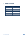
9
Default Parameters
9.1
Default Communication Parameters
RS-232
Baud Rate
115,200
Data Bits
8
Stop Bits
1
Parity
None
Command Format
ASCII
Example (Output 1 to Input 1)
#AV 1>1<CR>
Ethernet
IP Address
192.168.1.39
Subnet mask
255.255.255.0
Default gateway
192.168.1.1
TCP Port #
5000
UDP Port #
50000
Maximum UDP Ports
10
Maximum TCP Ports
4
FC-340 - Default Parameters
19
10
Kramer Protocol
The FC-340 supports the Kramer Protocol 3000.
The Protocol 3000 RS-232 communication protocol lets you control the machine
from any standard terminal software (for example, Windows® HyperTerminal
Application).
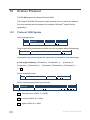
10.1
Protocol 3000 Syntax
Host message format:
Start
#
Address
(optional)
Destination_id@
Body
message
Delimiter
CR
Simple command (commands string with only one command without addressing):
start
body
#
delimiter
Command SP Parameter_1,Parameter_2,…
CR
Commands string (formal syntax with commands concatenation and addressing):
# Address@ Command_1 Parameter1_1,Parameter1_2,… |Command_2
Parameter2_1,Parameter2_2,… |Command_3 Parameter3_1,Parameter3_2,…
|…CR
Device message format:
Start
~
Address (optional)
Sender_id@
Body
message
Delimiter
CR LF
Device long response (Echoing command):
Start
Address
(optional)
~
Sender_id@
Body
command SP [param1 ,param2
Delimiter
…] result
CR LF
CR = Carriage return (ASCII 13 = 0x0D)
LF = Line feed (ASCII 10 = 0x0A)
SP = Space (ASCII 32 = 0x20)
20
FC-340 - Kramer Protocol
10.2
Command Part Details
Command:
Sequence of ASCII letters ('A'-'Z', 'a'-'z' and '-').
Command will separate from parameters with at least single space.
Parameters:
Sequence of Alfa-Numeric ASCII chars ('0'-'9','A'-'Z','a'-'z' and some special chars for specific commands), parameters will
be separated by commas.
Message string:
Every command must to be entered as part of message string that begin with message starting char and end with message
closing char, note that string can contain more then one command separated by pipe ("|") char.
Message starting char:
'#' for host command\query.
'~' for machine response.
Device address (Optional, for KNET):
KNET Device ID follow by '@' char.
Query sign = '?', will follow after some commands to define query request.
Message closing char =
Host messages - Carriage Return (ASCII 13), will be referred to by CR in this document.
Machine messages - Carriage Return (ASCII 13) + Line-Feed (ASCII 10), will be referred to by CRLF.
Spaces between parameters or command parts will be ignored.
Commands chain separator char:
When message string contains more than one command, commands will be separated by pipe ("|").
Commands entering:
If terminal software used to connect over serial \ ethernet \ USB port, that possible to directly enter all commands characters
(CR will be entered by Enter key, that key send also LF, but this char will be ignored by commands parser).
Sending commands from some controllers (like Crestron) require coding some characters in special form (like \X##).
Anyway, there is a way to enter all ASCII characters, so it is possible to send all commands also from controller.
(Similar way can use for URL \ Telnet support that maybe will be added in future).
Commands forms:
Some commands have short name syntax beside the full name to allow faster typing, response is always in long syntax.
Commands chaining:
It is possible to enter multiple commands in same string by '|' char (pipe).
In this case the message starting char and the message closing char will be entered just one time, in the string beginning
and at the end.
All the commands in string will not execute until the closing char will be entered.
Separate response will be sent for every command in the chain.
Input string max length:
64 characters.
Backward support:
Design note: transparent supporting for protocol 2000 will be implemented by switch protocol command from protocol 3000
to protocol 2000, in protocol 2000 there is already such a command to switch protocol to ASCII protocol (#56 : H38 H80
H83 H81).
FC-340 - Kramer Protocol
21
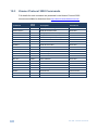
10.3
Kramer Protocol 3000 Commands
Full details for each command are presented in the Kramer Protocol 3000
document available for download from http://www.kramerelectronics.com.
Command
22
Cmd
Short
Description
Permission
#
Protocol handshaking
End User
BUILD-DATE?
Read device build date
End User
ETH-PORT
ETHP
Change protocol Ethernet port
Administrator
ETH-PORT?
ETHP?
Get protocol Ethernet port
End User
FACTORY
Reset to factory default configuration
HELP
List of commands
LDFW
Load new firmware
User SW Internal
MODEL?
Read device model
End User
Administrator
End User
NET-DHCP
NTDH
Set DHCP mode
NET-DHCP?
NTDH?
Get DHCP mode
End User
NET-GATE
NTGT
Set Gateway
Administrator
NET-GATE?
NTGT?
Get Gateway
End User
NET-IP
NTIP
Set IP address
Administrator
NET-IP?
NTIP?
Get IP address
End User
NET-MAC?
NTMC?
Read MAC address
End User
NET-MASK
NTMSK
Set subnet mask
Administrator
NET-MASK?
NTMSK?
Get subnet mask
End User
PROT-VER?
Read device protocol version
End User
RESET
Reset device
Administrator
SN?
Read device serial number
End User
VERSION?
Read device firmware version
End User
FC-340 - Kramer Protocol
For the latest information on our products and a list of Kramer distributors,
visit our Web site where updates to this user manual may be found.
We welcome your questions, comments, and feedback.
Web site: www.kramerelectronics.com
E-mail: [email protected]
!
SAFETY WARNING
Disconnect the unit from the power
supply before opening and servicing
P/N: 2900- 000768
Rev: 3