1
K R A ME R E LE CT R O N IC S L T D .
USER MANUAL
MODEL:
VS-82HDxl
8x2 SD /HD-SDI Matrix Switcher
P/N: 2900-300186 Rev 3
Contents
1
Introduction
1
2
2.1
2.2
2.3
Getting Started
Achieving the Best Performance
Safety Instructions
Recycling Kramer Products
2
2
3
3
3
3.1
4
Overview
Defining the VS-82HDxl 8x2 SD/HD-SDI Matrix Switcher
Installing in a Rack
4
6
8
5
5.1
5.2
5.3
5.4
5.5
6
6.1
6.2
6.3
6.4
6.5
6.6
6.7
6.8
6.9
7
Connecting the VS-82HDxl 8x2 SD/HD-SDI Matrix Switcher
Setting the Device Number and Termination DIP-Switches
Setting the Genlock Loop Termination
Connecting to the VS-82HDxl Using the RS-232 Connection
Cascading Multiple VS-82HDxl Devices Using the RS-485 Connection
Connecting to the VS-82HDxl Using Ethernet
Operating the VS-82HDxl 8x2 SD/HD-SDI Matrix Switcher
Switching Inputs to Outputs
Performing Two Switch Selections Simultaneously
Selecting Audio Channels
Muting and Unmuting an Output
Selecting a Genlock Signal
Storing and Recalling a Switch Setting from a Preset
Locking and Unlocking the Front Panel
Resetting the Device to Factory Default Values
Upgrading the Firmware
Technical Specifications
9
10
12
12
12
13
17
17
18
18
19
19
20
21
21
21
22
8
Default Communication Parameters
23
9
9.1
9.2
Kramer Protocol 3000
Kramer Protocol 3000 Syntax
Kramer Protocol 3000 Commands
24
24
27
Figures
Figure 1: VS-82HDxl 8x2 SD/HD-SDI Matrix Switcher Front Panel
Figure 2: VS-82HDxl 8x2 SD/HD-SDI Matrix Switcher Rear Panel
Figure 3: Connecting the VS-82HDxl 8x2 SD/HD-SDI Matrix Switcher
Figure 4: VS-82HDxl Setup DIP-Switches
Figure 5: Controlling Multiple VS-82HDxl Devices using RS-485 Serial Communication
Figure 6: Local Area Connection Properties Window
Figure 7: Internet Protocol (TCP/IP) Properties Window
6
7
9
10
13
15
15
VS-82HDxl - Contents
i
1
Introduction
Welcome to Kramer Electronics! Since 1981, Kramer Electronics has been
providing a world of unique, creative, and affordable solutions to the vast range of
problems that confront video, audio, presentation, and broadcasting professionals
on a daily basis. In recent years, we have redesigned and upgraded most of our
line, making the best even better!
Our 1,000-plus different models now appear in 11 groups that are clearly defined
by function: GROUP 1: Distribution Amplifiers; GROUP 2: Switchers and Routers;
GROUP 3: Control Systems; GROUP 4: Format/Standards Converters; GROUP 5:
Range Extenders and Repeaters; GROUP 6: Specialty AV Products; GROUP 7:
Scan Converters and Scalers; GROUP 8: Cables and Connectors; GROUP 9:
Room Connectivity; GROUP 10: Accessories and Rack Adapters and GROUP 11:
Sierra Video Products.
Congratulations on purchasing your Kramer VS-82HDxl 8x2 SD/HD-SDI Matrix
Switcher. This product is ideal for:
•
Professional broadcasting and production studios
•
Post production editing
VS-82HDxl - Introduction
1
2
Getting Started
We recommend that you:
Unpack the equipment carefully and save the original box and packaging
•
materials for possible future shipment
Review the contents of this user manual
•
Go to http://www.kramerelectronics.com to check for up-to-date
user manuals, application programs, and to check if firmware
upgrades are available (where appropriate).
i
2.1
Achieving the Best Performance
To achieve the best performance:
•
Use only good quality connection cables (we recommend Kramer highperformance, high-resolution cables) to avoid interference, deterioration in
signal quality due to poor matching, and elevated noise levels (often
associated with low quality cables)
•
Do not secure the cables in tight bundles or roll the slack into tight coils
•
Avoid interference from neighboring electrical appliances that may adversely
influence signal quality
•
Position your VS-82HDxl away from moisture, excessive sunlight and dust
!
2
This equipment is to be used only inside a building. It may only be
connected to other equipment that is installed inside a building.
VS-82HDxl - Getting Started
2.2
Safety Instructions
!
2.3
Caution:
There are no operator serviceable parts inside the unit
Warning:
Use only the power cord that is supplied with the unit
Warning:
Do not open the unit. High voltages can cause
electrical shock! Servicing by qualified personnel only
Warning:
Disconnect the power and unplug the unit from the wall
before installing
Recycling Kramer Products
The Waste Electrical and Electronic Equipment (WEEE) Directive 2002/96/EC
aims to reduce the amount of WEEE sent for disposal to landfill or incineration by
requiring it to be collected and recycled. To comply with the WEEE Directive,
Kramer Electronics has made arrangements with the European Advanced
Recycling Network (EARN) and will cover any costs of treatment, recycling and
recovery of waste Kramer Electronics branded equipment on arrival at the EARN
facility. For details of Kramer’s recycling arrangements in your particular country
go to our recycling pages at http://www.kramerelectronics.com/support/recycling/.
VS-82HDxl - Getting Started
3
3
Overview
The Kramer VS-82HDxl is a true 8 x 2 matrix switcher for SDI signals that lets you
switch any one of the eight SDI inputs to one or both sets of triple outputs (SDI and
HDMI).
In particular, the VS-82HDxl:
•
Features selector buttons that provide visual indication of the presence of a
signal
•
Provides up to 2.97Gbps of bandwidth allowing it to be used for SD, HD and
3G HD serial digital video signals
•
Includes cable equalization of up to 350m for SD signals, 140m for 1.5GHz
HD signals and 120m for 3GHz HD signals
•
Features reclocking and equalization on each input
•
Is SMPTE 259M, 292M, 344M, 424M and DVB-ASI compliant and supports
data rates of 270Mbps, 1483.5Mbps, 1485Mbps and 2970Mbps
Digital Video Broadcasting - Asynchronous Serial Interface
•
Supports ANC data (embedded audio, Teletext, time code, and so on)
•
Performs clean switching when the sources are genlocked to the selected
genlock input with a difference of no more than two lines of video
•
Can use either an analog signal or any of the SDI input signals for
genlocking. If the selected genlock input signal is unavailable, the
VS-82HDxl automatically selects the best available SDI input for the genlock
signal
•
Provides 16 presets for storing switching configurations
•
Has a front panel lock button
The VS-82HDxl is housed in a 19" 1U rack-mountable enclosure and is fed from a
100-240 VAC universal switching power supply.
4
VS-82HDxl - Overview
You can control the VS-82HDxl using the front panel buttons, or remotely via:
•
RS-232/RS-485 serial commands transmitted by a PC, touch screen system
or other serial controller
•
The Kramer RC-IR3 infrared remote control transmitter
•
A PC connected to the Ethernet port on the device via a LAN
VS-82HDxl - Overview
5
VS-82HDxl – Defining the VS-82H 8x2 HDMI Matrix Switcher
3.1
Defining the VS-82HDxl 8x2 SD/HD-SDI Matrix Switcher
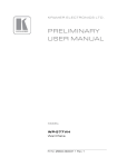
Figure 1 and Figure 2 define the front and rear panel of the VS-82HDxl respectively.
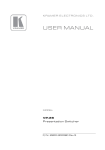
Figure 1: VS-82HDxl 8x2 SD/HD-SDI Matrix Switcher Front Panel
6
#
Feature
Function
1
IR LED
Lights yellow when receiving an IR signal
2
IR Receiver
Signal receiver for the infrared remote control transmitter
3
POWER LED
Lights green when the device is powered on
4
OFF Button
Press to mute the signal on Output 2 (see Section 6.4)
5
OFF Button
Press to mute the signal on Output 1
6
INPUT SELECTOR To OUT 2 1~8 Buttons
Press one of the eight inputs to switch it to Output 2 (see Section 6.1)
7
INPUT SELECTOR To OUT 1 1~8 Buttons
Press one of the eight inputs to switch it to Output 1
8
AUDIO Button
Press to select which SDI audio group to transmit on the output (see Section 6.3)
9
PANEL LOCK Button
Press and hold to lock the front panel buttons. Press and hold again to unlock the front panel buttons
10
TAKE Button
Press to implement simultaneous switching actions (see Section 6.2)
11
STO Button
Press to store a switching configuration in a preset (see Section 6.7) Press together with the RCL button
to select a genlock synchronization source (see Section 6.5)
12
RCL Button
Press to recall a preset configuration (see Section 6.7). Press together with the STO button to select a
genlock synchronization source (see Section 6.5)
7
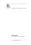
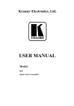
Figure 2: VS-82HDxl 8x2 SD/HD-SDI Matrix Switcher Rear Panel
VS-82HDxl – Defining the VS-82H 8x2 HDMI Matrix Switcher
#
Feature
Function
1
SDI INPUTS IN 1 ~ IN 8 BNC Connectors
Connect to the SDI video sources (from 1 to 8)
2
SDI OUTPUTS
BNC Connectors
3
RESET Button
Press while turning on the device to reset the device to factory default values (see Section 6.8 and
Section 8)
4
PROG Button
For the use of Kramer service personnel only
5
RS-485 3-pin Terminal Block
Connect to an RS-485 serial controller (see Section 5.4)
6
SETUP DIP-switches Terminal Block
Use to set the RS-485 bus device number and termination (see Section 5.1)
7
ETHERNET RJ-45 Connector
Connect to a PC via a LAN (see Section 5.5)
8
Mains Power Connector, Fuse and Switch
Plug in the power cord and switch the device on and off
9
10
11
GENLOCK
(ANALOG)
OUT 1A and OUT 1B
Connect to the SDI video acceptors (1 and 2).
Note: The same signal is present on both outputs as well as on the HDMI 1 output
OUT 2A and OUT 2B
Connect to the SDI video acceptors (3 and 4).
Note: The same signal is present on both outputs as well as on the HDMI 2 output
IN BNC Connector
Connect to the genlock source (see Section 6.5)
TERM Button
Press to terminate the genlock source (75Ω). Release for looping
LOOP BNC Connector
Connect to the Genlock connector of the next device in the chain
OUT 1
Connect to the first HDMI acceptor.
Note: The same signal that is present on OUT 1A and OUT 1B is present on this HDMI output
OUT 2
Connect to the second HDMI acceptor.
Note: The same signal that is present on OUT 2A and OUT 2B is present on this HDMI output
12
HDMI
OUTPUTS
13
RS-232 9-pin D-sub Serial Connector
Connect to a PC/serial controller (see Section 5.3)
4
Installing in a Rack
This section provides instructions for rack mounting the unit.
8
VS-82HDxl - Installing in a Rack
5
Connecting the VS-82HDxl 8x2 SD/HD-SDI
Matrix Switcher
You can use your VS-82HDxl to switch one of the eight HD/SD SDI inputs to
either or both of the two pairs of SDI outputs and the HDMI outputs. The same
output signal (selected using the To OUT 1 input buttons) is replicated on SDI
OUT 1A, SDI OUT 1B and HDMI OUT 1. The same output signal (selected using
the To OUT 2 input buttons) is replicated on SDI OUT 2A, SDI OUT 2B and HDMI
OUT 2.
i
Always switch off the power to each device before connecting it to your
VS-82HDxl. After connecting your VS-82HDxl, connect its power and
then switch on the power to each device.
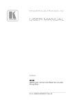
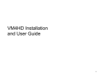
Figure 3: Connecting the VS-82HDxl 8x2 SD/HD-SDI Matrix Switcher
VS-82HDxl - Connecting the VS-82HDxl 8x2 SD/HD-SDI Matrix Switcher
9
To connect the VS-82HDxl 8x2 SD/HD-SDI Matrix Switcher as illustrated in
the example in Figure 3:
1. Connect up to eight SDI sources to the SDI Input BNC connectors, (for
example, HD/SD SDI cameras to Input 1, 2 and 7, and an SDI VTR to
Input 8).
2. Connect the SDI Output BNC connectors to up to four SDI acceptors (for
example, HD/SD SDI displays to outputs 1A and 2A).
3. Connect the two HDMI output connectors to up to two HDMI acceptors (for
example, a projector to HDMI OUT 1).
4. If required, set the DIP-switches (see Section 5.1).
5. If required, connect and set the genlocking source (see Section 5.2 and
Section 6.5).
6. If required, connect a controller to the:
RS-232 port (see Section 5.3)
RS-485 port (see Section 5.4)
Ethernet connector (see Section 5.5)
7. Connect the power cord and power the device on.
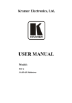
5.1
Setting the Device Number and Termination
DIP-Switches
When connecting more than one device using the RS-485 bus, you must set the
device number and the bus termination on the Setup DIP-switches accordingly.
Figure 4: VS-82HDxl Setup DIP-Switches
The following table defines the functions of each switch.
10
VS-82HDxl - Connecting the VS-82HDxl 8x2 SD/HD-SDI Matrix Switcher
DIP-switch
Function
1
RS-485 termination
2
RS-485 device ID
3
RS-485 device ID
4
RS-485 device ID
5
RS-485 device ID
6
Not used
7
Not used
8
Not used
Switches that are up are off and those that are down are on. By default, all
DIP-switches are set to OFF (up).
5.1.1
Setting the Device ID
The device ID determines the position of a VS-82HDxl in the RS-485 bus. You can
set the device ID using the Setup DIP-switches 2, 3, 4 and 5.
Device ID
DIP-switch
2
DIP-switch
3
DIP-switch
4
DIP-switch
5
1 (default)
Off
Off
Off
Off
1
On
Off
Off
Off
2
Off
On
Off
Off
3
On
On
Off
Off
4
Off
Off
On
Off
5
On
Off
On
Off
6
Off
On
On
Off
7
On
On
On
Off
8
Off
Off
Off
On
9
On
Off
Off
On
10
Off
On
Off
On
11
On
On
Off
On
12
Off
Off
On
On
13
On
Off
On
On
14
Off
On
On
On
15
On
On
On
On
When using a standalone VS-82HDxl unit, set the device ID to 1. When connecting multiple
devices to a PC using an RS-232 connection (as in Figure 5), set the first device that is closest
to the PC (the master) to be device ID 1.
VS-82HDxl - Connecting the VS-82HDxl 8x2 SD/HD-SDI Matrix Switcher
11
5.1.2
Setting the RS-485 Bus Termination
The devices at the ends of the RS-485 bus must be terminated, all others must be
unterminated.
5.2
DIP-switch 1
Termination State
Off
Off
On
On
Setting the Genlock Loop Termination
The genlock loop must be terminated if the loop ends at the VS-82HDxl.
To terminate the Genlock loop:
•
Depress the Genlock Term button.
The Genlock loop is terminated
5.3
Connecting to the VS-82HDxl Using the RS-232
Connection
You can connect to the VS-82HDxl via an RS-232 connection using, for example,
a PC. Note that a null-modem adapter/connection is not required.
To connect to the VS-82HDxl via RS-232:
•
Connect the RS-232 9-pin D-sub rear panel port on the VS-82HDxl unit via a
9-wire straight cable (only pin 2 to pin 2, pin 3 to pin 3, and pin 5 to pin 5
need to be connected) to the RS-232 9-pin D-sub port on your PC
5.4
Cascading Multiple VS-82HDxl Devices Using the
RS-485 Connection
To cascade up to eight individual VS-82HDxl units as shown in the example
in Figure 5:
1. Connect the “A” (+) and “B” (-) pins on the RS-485 terminal block port on
each of the VS-82HDxl devices. (If using shielded twisted pair cable, the
shield is connected to the “G” (Ground) pin of the first unit).
12
VS-82HDxl - Connecting the VS-82HDxl 8x2 SD/HD-SDI Matrix Switcher
2. Connect the serial controller, (for example, a PC) to the first device (ID 1 or
master) using an RS-232 connection (see Section 5.3).
3. Set the first VS-82HDxl unit as device ID 1 and the following seven
VS-82HDxl units as device ID 2 to device ID 8.
Figure 5: Controlling Multiple VS-82HDxl Devices using RS-485 Serial Communication
5.5
Connecting to the VS-82HDxl Using Ethernet
You can connect the VS-82HDxl via the Ethernet, using a crossover cable (see
Section 5.5.2) for direct connection to the PC or a straight through cable (see
Section 5.5.3) for connection via a network hub or network router.
After connecting the Ethernet port, you have to install and configure your Ethernet Port. For
detailed instructions, see the “Ethernet Configuration (FC-11) guide.pdf” file in the technical
support section at http://www.kramerelectronics.com.
VS-82HDxl - Connecting the VS-82HDxl 8x2 SD/HD-SDI Matrix Switcher
13
5.5.1
Configuring the Ethernet Port
After connecting the Ethernet port, you have to install and configure it.
For detailed instructions on how to install and configure your Ethernet port, see the Ethernet
Configuration (FC-11) guide.pdf on our Web site at http://www.kramerelectronics.com.
5.5.2
Connecting the Ethernet Port Directly to a PC
You can connect the Ethernet port of the VS-82HDxl to the Ethernet port on your
PC via a crossover cable with RJ-45 connectors.
i
This type of connection is recommended for identification of the factory
default IP Address of the VS-82HDxl during the initial configuration
After connecting the Ethernet port, configure your PC as follows:
1. On your desktop, right-click the My Network Places icon.
2. Select Properties.
3. Right-click Local Area Connection Properties.
4. Select Properties.
The Local Area Connection Properties window appears.
5. Select the Internet Protocol (TCP/IP) and click the Properties Button (see
Figure 6).
14
VS-82HDxl - Connecting the VS-82HDxl 8x2 SD/HD-SDI Matrix Switcher
Figure 6: Local Area Connection Properties Window
6. Select Use the following IP Address, and fill in the details as shown in
Figure 7.
7. Click OK.
Figure 7: Internet Protocol (TCP/IP) Properties Window
VS-82HDxl - Connecting the VS-82HDxl 8x2 SD/HD-SDI Matrix Switcher
15
5.5.3
Connecting the Ethernet Port via a Network Hub
You can connect the Ethernet port of the VS-82HDxl to the Ethernet port on a
network hub or network router, via a straight through cable with RJ-45 connectors.
16
VS-82HDxl - Connecting the VS-82HDxl 8x2 SD/HD-SDI Matrix Switcher
6
Operating the VS-82HDxl 8x2 SD/HD-SDI
Matrix Switcher
This section describes:
6.1
•
Switching inputs to outputs (see Section 6.1)
•
Performing two switch selections simultaneously (see Section 6.2)
•
Selecting audio channels (see Section 6.3)
•
Muting and unmuting an output (see Section 6.4)
•
Selecting a genlock signal (see Section 6.5)
•
Storing and recalling a switch setting from a preset (see Section 6.6)
•
Locking and unlocking the front panel buttons (see Section 6.7)
•
Resetting to the factory default values (see Section 6.8)
•
Upgrading the firmware (see Section 6.9)
Switching Inputs to Outputs
If there is a signal present on a selected input the relevant button lights solid. If a
selected input or output has no signal present, the button flashes.
To switch an input to an output, for example, Input 6 to Output 1, and Input 3
to Output 2:
1. Press Input 6 on the top row (To Output 1).
Input 6 is switched to Output 1.
2. Press Input 3 on the bottom row (To Output 2).
Input 3 is switched to Output 2.
Note: You can also perform two input selections and have them activated
simultaneously by pressing the Take button (see Section 6.2).
VS-82HDxl - Operating the VS-82HDxl 8x2 SD/HD-SDI Matrix Switcher
17
6.2
Performing Two Switch Selections Simultaneously
You can activate two switch selections simultaneously using the Take button.
To perform two switch selections simultaneously:
1. Press the Take button.
The Take button flashes.
2. Select an input on the top row to switch to Output 1.
The selected Input button flashes.
3. Select an input on the bottom row to switch to Output 2.
The selected Input button flashes.
4. Press the Take button.
The Take button no longer flashes, the inputs that were selected light solid
and the switching changes are performed.
6.3
Selecting Audio Channels
The VS-82HDxl can select two audio channels of the possible 16 present in the
SDI signals and output them to either of the HDMI outputs, provided there is an
appropriate HDMI output signal in which to embed them.
Under normal circumstances (the Audio button is not lit) AFV (audio-follows-video)
switching is performed. When the Audio button is lit, the number 8 Input selector
buttons allow you to select any one of eight stereo pairs (that is, two of 16 audio
channels).
Note: This selection applies only to the HDMI outputs. All audio channels are
always present in the SDI output signal. Muting an output mutes the audio on the
HDMI only, not on the SDI outputs.
To select a stereo audio pair to switch to an HDMI output, for example,
stereo audio pair 5 to HDMI Output 2:
1.
Press the Audio button.
The Audio button lights.
18
VS-82HDxl - Operating the VS-82HDxl 8x2 SD/HD-SDI Matrix Switcher
2. Press Input 5 on the bottom row.
Stereo input pair 5 (that is, audio channels 9 and 10) is switched to HDMI
Output 2.
3. Press the Audio button to return to AFV switching mode.
The Audio button no longer lights.
6.4
Muting and Unmuting an Output
To mute and unmute the signal on Output 2:
1. Press the Off button on the bottom row.
The Off button lights, the selected Input button is no longer lit and the signal
is muted.
2. Press the Off button on the bottom row again.
The Off button no longer lights, the selected Input button lights and the
signal is unmuted.
6.5
Selecting a Genlock Signal
The genlock feature lets you switch genlocked video signals governed by the
timing of the genlock reference input.
According to SMPTE RP-168, in order to switch cleanly, the sources must be
precisely genlocked to the Genlock input. The VS-82HDxl provides clean
switching only when there is an error of no more than two TV lines.
To select a genlock signal:
1. Connect the Genlock cable.
2. Press and hold STO and RCL simultaneously.
Both buttons light.
VS-82HDxl - Operating the VS-82HDxl 8x2 SD/HD-SDI Matrix Switcher
19
3. Select the Genlock input:
If you want to use one of the digital inputs, select the input that you want to
use for the genlock.
The selected input button lights and the input is selected,
Or,
If you want to use the analog genlock input, press the Off button.
The Off button lights and the analog genlock signal is selected.
4. Press and hold the STO and RCL buttons simultaneously.
Both buttons no longer light.
6.6
Storing and Recalling a Switch Setting from a Preset
You can use the store facility to remember up to 16 switch configurations and
recall any of them at a later time using the RCL button.
To store a setting:
1. Select the switching configuration that you want to store by pressing the
required Input buttons.
2. Press and hold the STO button.
The STO button and the last selected preset button lights.
3. Press the number of the preset in which you want to store the configuration,
where the top row of Input buttons represents preset numbers 1 to 8 (left to
right), and the bottom row represents 9 to 16.
The selected preset number lights.
4. Press and hold the STO button.
The STO button no longer lights and the selected inputs flash.
To recall a setup:
1. Press and hold the RCL button.
The RCL button lights as well as the last selected preset number.
20
VS-82HDxl - Operating the VS-82HDxl 8x2 SD/HD-SDI Matrix Switcher
2. Press the required preset number that you want to recall.
The RCL button no longer lights and the retrieved configuration input buttons
light.
6.7
Locking and Unlocking the Front Panel
To lock and unlock the front panel buttons:
1. Press and hold the Panel Lock button until the button lights.
The front panel buttons are locked.
2. Press and hold the Panel Lock button again until the button no longer lights.
The front panel buttons are unlocked.
6.8
Resetting the Device to Factory Default Values
To reset to factory default values:
1. Turn the VS-82HDxl off.
2. Press and hold the Reset button on the rear panel while turning the device
on.
3. After approximately five seconds release the Reset button.
The device is reset to its factory default values (see Section 8).
6.9
Upgrading the Firmware
For instructions on upgrading the firmware see “Upgrading the VS-82HDxl
Firmware Using the K-Upload Software”.
Note: When updating the firmware, the device number must be set to 1, (see
Section 5.1.1).
VS-82HDxl - Operating the VS-82HDxl 8x2 SD/HD-SDI Matrix Switcher
21
7
Technical Specifications
INPUTS:
8 SDI on BNC
Connectors
SD
SMPTE-259M
HD
SMPTE-292
3G
SMPTE-424M
SMPTE-125M
ITU-R BT.656-5
SMPTE-296M
SMPTE-274M
SMPTE-296M
480i-60
576i-50
720p-60/50/59.9
1080i-60/50/59.9
1080p-29.9/59.9/
60/50/30/25/23.9/ 24
1808psf-23.9/24/
25/29.9/30
1080p-59.94/60/50
1 GENLOCK 75Ω/Hi-Z on looping BNC connectors, bi-level, tri-level inputs
OUTPUTS:
4 SDI on BNC
Connectors
HD
SMPTE-292
SMPTE-296M
720p-59.9/60/50
3G
SMPTE-424M
SMPTE-296M
1080p-59.9/60/50
2 HDMI Connectors
1 GENLOCK 75Ω/Hi-Z on looping BNC connectors, bi-level, tri-level inputs
DATA RATE:
Up to 2.97Gbps
POWER
CONSUMPTION:
100−240V AC, 50/60Hz, 23VA
CONTROLS:
Front panel buttons, infrared remote control transmitter, RS-232, Ethernet
OPERATING
TEMPERATURE:
0° to +40°C (32° to 104°F)
STORAGE
TEMPERATURE:
–40° to +70°C (–40° to 158°F)
HUMIDITY:
10% to 90%, RHL non-condensing
DIMENSIONS:
19” x 7.24” x 1U (W, D, H)
WEIGHT:
1.6kg (3.53lbs) approx.
ACCESSORIES:
Power cord, IR transmitter, rack ”ears”
Specifications are subject to change without notice at http://www.kramerelectronics.com
22
VS-82HDxl - Technical Specifications
8
Default Communication Parameters
RS-232
Protocol 3000
Baud Rate:
115,200
Data Bits:
8
Stop Bits:
1
Parity:
None
Command Format:
ASCII
Example (Output 1 to Input 1):
#AV 1>1<CR>
Ethernet
IP Address:
192.168.1.39
TCP Port #:
5000
UDP Port #:
50000
VS-82HDxl - Default Communication Parameters
23
9
Kramer Protocol 3000
The VS-82HDxl can be operated using serial commands from a PC, remote
controller or touch screen using the Kramer Protocol 3000.
This section describes the:
9.1
•
Kramer Protocol 3000 syntax (see Section 9.1)
•
Kramer Protocol 3000 commands (see Section 9.2)
Kramer Protocol 3000 Syntax
9.1.1
Host Message Format
Start
Address (optional)
Body
Delimiter
#
device_id@
Message
CR
9.1.1.1
Simple Command
Command string with only one command without addressing:
Start
Body
Delimiter
#
Command SP Parameter_1,Parameter_2,…
CR
9.1.1.2
Command String
Formal syntax with commands concatenation and addressing:
Start
Address
Body
Delimiter
#
device_id@
Command_1 Parameter1_1,Parameter1_2,…|
Command_2 Parameter2_1,Parameter2_2,…|
Command_3
Parameter3_1,Parameter3_2,…|…
CR
9.1.2
Device Message Format
Start
Address (optional)
Body
delimiter
~
device_id@
Message
CR LF
9.1.2.1
Device Long Response
Echoing command:
Start
Address (optional)
Body
Delimiter
~
device_id@
Command SP [Param1 ,Param2 …] result
CR LF
CR = Carriage return (ASCII 13 = 0x0D)
LF = Line feed (ASCII 10 = 0x0A)
SP = Space (ASCII 32 = 0x20)
24
VS-82HDxl - Kramer Protocol 3000
9.1.3
Command Terms
Command
A sequence of ASCII letters ('A'-'Z', 'a'-'z' and '-').
Command and parameters must be separated by at least one space.
Parameters
A sequence of alphanumeric ASCII characters ('0'-'9','A'-'Z','a'-'z' and some special
characters for specific commands). Parameters are separated by commas.
Message string
Every command entered as part of a message string begins with a message
starting character and ends with a message closing character.
Note: A string can contain more than one command. Commands are separated by
a pipe ( '|' ) character.
Message starting character
'#' – For host command/query
'~' – For device response
Device ID (Optional, for K-NET)
K-NET Device ID followed by '@'
Query sign
'?' follows some commands to define a query request.
Message closing character
CR – For host messages; carriage return (ASCII 13)
CRLF – For device messages; carriage return (ASCII 13) + line-feed (ASCII 10)
Command chain separator character
When a message string contains more than one command, a pipe ( '|' ) character
separates each command.
Spaces between parameters or command terms are ignored.
VS-82HDxl - Kramer Protocol 3000
25
9.1.4
Entering Commands
You can directly enter all commands using a terminal with ASCII communications
software, such as HyperTerminal, Hercules, etc. Connect the terminal to the serial
or Ethernet port on the Kramer device. To enter CR press the Enter key.
( LF is also sent but is ignored by command parser).
For commands sent from some non-Kramer controllers like Crestron, some
characters require special coding (such as, /X##). Refer to the controller manual.
9.1.5
Command Forms
Some commands have short name syntax in addition to long name syntax to allow
faster typing. The response is always in long syntax.
9.1.6
Chaining Commands
Multiple commands can be chained in the same string. Each command is
delimited by a pipe character (“|”). When chaining commands, enter the message
starting character and the message closing character only once, at the
beginning of the string and at the end.
Commands in the string do not execute until the closing character is entered.
A separate response is sent for every command in the chain.
9.1.7
Maximum String Length
64 characters
26
VS-82HDxl - Kramer Protocol 3000
9.2
Kramer Protocol 3000 Commands
Command
Short
Form
#
Description
Permission
Protocol handshaking
End User
AUD
Switch audio only
End User
AUD?
Read audio connection
End User
AV
Switch audio and video
Customer
BAUD
Set protocol serial port baud rate
End User
BAUD?
Get protocol serial port baud rate
End User
BUILD-DATE?
Read device build date
End User
ETH-PORT
ETHP
Change protocol Ethernet port
Admin
ETH-PORT?
ETHP?
Query protocol Ethernet port
End User
FACTORY
Reset to factory default configuration
GNLCK
Set Genlock State
End User
GNLCK?
Get Genlock State
End User
LDFPGA
Load new FPGA file
Admin
LDFW
Load new firmware
User SW Internal
LOCK-FP
LCK
Lock front panel
Administrator
LOCK-FP?
LCK?
Read lock front panel
End User
LOGIN
Login – Get protocol permission
No Secure
LOGIN?
Get login level
No Secure
LOGOUT
Logout
No Secure
MACH-NUM
Set Machine number
Admin
MODEL?
Read device model
End User
NAME
Set machine (DNS) name
Admin
NAME?
Query machine (DNS) name
End User
NAME-RST
Reset machine name to factory default
(DNS)
Admin
Admin
NET-DHCP
NTDH
Set DHCP mode
NET-DHCP?
NTDH?
Query DHCP mode
End User
NET-GATE
NTGT
Set Gateway
Admin
NET-GATE?
NTGT?
Query Gateway
End User
NET-IP
NTIP
Set IP address
Admin
NET-IP?
NTIP?
Query IP address
End User
NET-MAC?
NTMC?
Query MAC address
End User
NET-MASK
NTMSK
Set subnet mask
Admin
NET-MASK?
NTMSK? Read subnet mask
End User
PASS
Set Password
Admin
PASS?
Get Password
Admin
PROT-VER?
Read device protocol version
End User
PRST-RCL
Recall saved preset
End User
PRST-STO
Store current connections to preset
End User
RESET
Reset device
Administrator
SECUR
Start/Stop Security
Admin
SECUR?
Get security state
No Secure
SN?
Read device serial number
End User
VS-82HDxl - Kramer Protocol 3000
27
Command
Description
Permission
Execute firmware upgrade
Admin
VERSION?
Read device firmware version
End User
VID
Switch video only
End User
VID?
Read video connection
End User
VID-RES?
Get video switch state
End User
UPGRADE
28
Short
Form
VS-82HDxl - Kramer Protocol 3000
For the latest information on our products and a list of Kramer distributors,
visit our Web site where updates to this user manual may be found.
We welcome your questions, comments, and feedback.
Web site: www.kramerelectronics.com
E-mail: [email protected]
!
SAFETY WARNING
Disconnect the unit from the power
supply before opening and servicing
P/N: 2900- 300186
Rev: 3