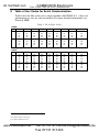
1
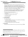
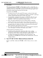
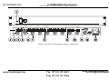
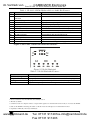
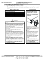
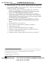
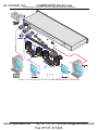
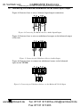
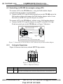
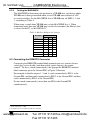
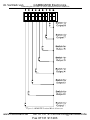
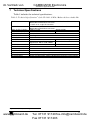
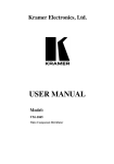
im Vertrieb von
CAMBOARD Electronics
Kramer Electronics, Ltd.
USER MANUAL
Model:
VP-108
1:8 XGA / Balanced Stereo Audio DA
www.camboard.de
Tel. 07131 [email protected]
Fax 07131 911203
im Vertrieb von
CAMBOARD
Electronics
Contents
Contents
1
2
Introduction
Getting Started
1
1
3
4
5
6
Overview
Your VP-108 1:8 XGA / Balanced Stereo Audio DA
Installing the VP-108 in a Rack
Connecting the VP-108 1:8 XGA / Balanced Stereo Audio DA
3
3
6
7
7
8
Technical Specifications
Table of Hex Codes for Serial Communication
2.1
6.1
6.2
6.2.1
6.2.2
6.3
Quick Start
1
Connecting the Balanced/Unbalanced Stereo Audio Input/Output
Controlling via RS-232 (for example, using a PC)
Setting the Dipswitches
Setting the MACHINE #
Connecting the REMOTE Connector
9
8
8
9
9
11
12
Figures
Figure 1: VP-108 1:8 XGA / Balanced Stereo Audio DA
Figure 2: VP-108 Underside
Figure 3: Connecting the VP-108 1:8 XGA / Balanced Stereo Audio DA
Figure 4: Connecting the Balanced Stereo Audio Input/Output
Figure 5: Connecting the Unbalanced Stereo Audio Output
Figure 6: Connecting an Unbalanced Source to the Balanced VP-108 Input
Figure 7: Connecting a VP-108 Unit to a PC without using a Null-modem Adapter
Figure 8: SETUP Dipswitches
Figure 9: REMOTE Terminal Block Connector
4
5
8
9
9
9
8
8
10
Tables
Table 1: VP-108 1:8 XGA / Balanced Stereo Audio DA Features
Table 2: VP-108 Underside Features
Table 3: Dipswitch Settings
Table 4: Machine # Dipswitch Settings
Table 5: Technical Specifications of the VP-108 1:8 XGA / Balanced Stereo Audio DA
Table 6: VP-108 Hex Codes
www.camboard.de
5
5
8
9
11
12
i
Tel. 07131 [email protected]
Fax 07131 911203
im Vertrieb von
1
CAMBOARD
Electronics
Introduction
Introduction
Welcome to Kramer Electronics! Since 1981, Kramer Electronics has been
providing a world of unique, creative, and affordable solutions to the vast range
of problems that confront the video, audio, presentation, and broadcasting
professional on a daily basis. In recent years, we have redesigned and upgraded
most of our line, making the best even better! Our 1,000-plus different models
now appear in 11 groups1 that are clearly defined by function.
Congratulations on purchasing your Kramer VP-108 1:8 XGA / Balanced
Stereo Audio DA (distribution amplifier), which is ideal for using with
presentation systems, and video duplication and production studios.
The package includes the following items:
VP-108 1:8 XGA / Balanced Stereo Audio DA
Power cord
Windows®-based Kramer control software
Null-modem adapter
This user manual2
2
Getting Started
We recommend that you:
Unpack the equipment carefully and save the original box and packaging
materials for possible future shipment
Review the contents of this user manual
Use Kramer high performance high resolution cables3
2.1 Quick Start
This quick start chart summarizes the basic steps when connecting a VP-108:
1 GROUP 1: Distribution Amplifiers; GROUP 2: Switchers and Matrix Switchers; GROUP 3: Control Systems; GROUP 4:
Format/Standards Converters; GROUP 5: Twisted-Pair Solutions; GROUP 6: Specialty AV Products; GROUP 7: Scan
Converters and Scalers; GROUP 8: Cables and Connectors; GROUP 9: Room Connectivity; GROUP 10: Accessories and
Rack Adapters; GROUP 11: Sierra Products
2 Download up-to-date Kramer user manuals from the Internet at this URL: http://www.kramerelectronics.com
3 The complete list of Kramer cables is on our Web site at http://www.kramerelectronics.com
www.camboard.de
1
Tel. 07131 [email protected]
Fax 07131 911203
im Vertrieb von
2
www.camboard.de
CAMBOARD
Electronics
Getting Started
KRAMER: SIMPLE CREATIVE TECHNOLOGY
Tel. 07131 911201
[email protected]
Fax 07131 911203
im Vertrieb von
3
CAMBOARD
Electronics
Overview
Overview
The high-performance VP-108 1:8 XGA / Balanced Stereo Audio DA is an
8-channel distribution amplifier for VGA/XGA and stereo audio (balanced or
unbalanced) that uses 15-pin HD connectors for the VGA-type signals, and
detachable terminal block connectors for the audio.
In particular, the VP-108:
Is unique in that each of the eight XGA outputs, and each of the eight
stereo audio outputs, may be individually enabled or disabled1, replacing a
switcher which would typically be used in such setups
Is controllable (switching of the outputs) via RS-232 or RS-485 serial
commands transmitted by a touch screen system, PC, or other serial
controller, as well as via external dry contact switches
Stores the output configuration in non-volatile memory so that the
machine will restore its power-down status when power is returned
Uses solid-state electronic switching, and low-noise amplifying circuitry
throughout the unit, and the sync pulses are detected and reconstructed
before amplifying and buffering to the outputs
Has a high video bandwidth, ensuring that each unit remains transparent
even at the highest resolution VGA modes such as XGA
Achieving the best performance means:
Connecting only good quality connection cables, thus avoiding
interference, deterioration in signal quality due to poor matching, and
elevated noise levels (often associated with low quality cables)
Avoiding interference from neighboring electrical appliances and
positioning your VP-108 unit in a location free from moisture, excessive
sunlight and dust
4
Your VP-108 1:8 XGA / Balanced Stereo Audio DA
Figure 1 and Table 1 define the VP-108 1:8 XGA / Balanced Stereo Audio
DA:
1 Using the REMOTE connector (see section 6.3) or via RS-232 or RS-485
www.camboard.de
3
Tel. 07131 [email protected]
Fax 07131 911203
im Vertrieb von
CAMBOARD Electronics
Your VP-108 1:8 XGA / Balanced Stereo Audio DA
GBA
Figure 1: VP-108 1:8 XGA / Balanced Stereo Audio DA
4
www.camboard.de
Tel. 07131 911201
Fax 07131 911203
[email protected]
KRAMER: SIMPLE CREATIVE TECHNOLOGY
im Vertrieb von
CAMBOARD Electronics
Your VP-108 1:8 XGA / Balanced Stereo Audio DA
Table 1: VP-108 1:8 XGA / Balanced Stereo Audio DA Features
#
1
2
3
4
5
6
7
8
9
10
11
12
13
Feature
POWER Switch
AUDIO INPUT Terminal Block
Connector
XGA INPUT 15-pin HD Connector
LEFT LEVEL Trimmer
RIGHT LEVEL Trimmer
LOOP 15-pin HD Connector
OUTPUT Terminal Block Connectors
OUTPUT 15-pin HD Connectors
REMOTE Terminal Block Connectors
RS-485 Connector
RS-232 9-pin D-sub Connector
SETUP Dipswitches
Power Connector with Fuse
Function
Illuminated switch for turning the unit ON or OFF
Connect to the balanced stereo audio source
Connect to the XGA source
1
Adjust the left output signal level
Adjust1 the right output signal level
For looping to increase output availability
Connect to the balanced stereo audio acceptors (from 1 to 8)
Connect to the XGA acceptors (from 1 to 8)
Connect to the contact closure switches
RS-485 detachable terminal block port
Connect to PC or other Serial Controller
Dipswitches for setup of the unit
AC connector enabling power supply to the unit
Figure 2 and Table 2 define the underside controls:
Figure 2: VP-108 Underside
Table 2: VP-108 Underside Features
Feature
ID BIT Switch
4
TERMINATION Switch
4
EQ. Trimmers
4
LEVEL Trimmers
Function
2
3
Set to ON position to select the ID BIT
Set to ON position2 to terminate with 75 , or move to Hi-Z for looping
Adjust1 the cable compensation equalization levels for blue, green and red
Adjust1 the output signal levels for blue, green and red
1 Insert a screwdriver into the small hole and carefully rotate it
2 The factory default
3 Sometimes notebook computers refuse to output a VGA signal to an external VGA monitor if they do not detect the ID BIT
as ON. Set the ID BIT to ON using this switch so that the notebook will output to an external VGA monitor
4 Separately for Blue (B), Green (G) and Red (R)
www.camboard.de
5
Tel. 07131 [email protected]
Fax 07131 911203
im Vertrieb von
5
CAMBOARD Electronics
Installing the VP-108 in a Rack
Installing the VP-108 in a Rack
This section describes what to do before installing in a rack and how to rack
mount.
Before Installing in a Rack
Before installing in a rack, be sure that the environment is
within the recommended range:
Operating temperature range +5º to +45º C (41º to 113º F)
Operating humidity range
10 to 90% RHL, non-condensing
Storage temperature range
-20º to +70º C (-4º to 158º F)
Storage humidity range
5 to 95% RHL, non-condensing
How to Rack Mount
To rack-mount a machine:
1. Attach both ear brackets to the
machine. To do so, remove the
screws from each side of the
machine (3 on each side), and
replace those screws through the
ear brackets.
CAUTION!!
When installing in a 19" rack, avoid hazards by taking
care that:
1. It is located within the recommended environmental
conditions, as the operating ambient temperature of a
closed or multi unit rack assembly may exceed the
room ambient temperature.
2. Once rack mounted, enough air will still flow around
the machine.
3. The machine is placed straight in the correct
horizontal position.
4. You do not overload the circuit(s). When connecting
the machine to the supply circuit, overloading the
circuits might have a detrimental effect on overcurrent
protection and supply wiring. Refer to the appropriate
nameplate ratings for information. For example, for
fuse replacement, see the value printed on the
product label.
5. The machine is earthed (grounded) in a reliable way
and is connected only to an electricity socket with
grounding. Pay particular attention to situations where
electricity is supplied indirectly (when the power cord
is not plugged directly into the socket in the wall), for
example, when using an extension cable or a power
strip, and that you use only the power cord that is
supplied with the machine.
6
www.camboard.de
2. Place the ears of the machine
against the rack rails, and insert the
proper screws (not provided)
through each of the four holes in the
rack ears.
Note that:
In some models, the front panel
may feature built-in rack ears
Detachable rack ears can be
removed for desktop use
Always mount the machine in the
rack before you attach any cables
or connect the machine to the
power
If you are using a Kramer rack
adapter kit (for a machine that is not
19"), see the Rack Adapters user
manual for installation instructions
(you can download it at:
http://www.kramerelectronics.com)
KRAMER: SIMPLE CREATIVE TECHNOLOGY
Tel. 07131 911201
[email protected]
Fax 07131 911203
im Vertrieb von
CAMBOARD Electronics
Connecting the VP-108 1:8 XGA / Balanced Stereo Audio DA
6
Connecting the VP-108 1:8 XGA / Balanced Stereo Audio DA
To connect the VP-108 1:8 XGA / Balanced Stereo Audio DA, as the example
in Figure 3 illustrates, do the following1:
1. Connect the XGA graphics source (for example, a PC) to the XGA
INPUT 15-pin HD connector, and connect2 the balanced stereo audio
source to the AUDIO INPUT terminal block connector.
2. Connect up to 8 XGA OUTPUT 15-pin HD connectors to the XGA
acceptors (for example, XGA monitors), and connect2 the corresponding
AUDIO OUTPUT terminal block connectors to the stereo audio acceptors
(for example, pairs of stereo loudspeakers).
3. Connect the LOOP 15-pin HD connector (OPTIONAL) to the XGA
INPUT 15-pin HD connector on an additional unit to increase video
outputs.
4. Set the dipswitches (see section 6.2.1).
5. Set the switches on the underside for looping3 (see Figure 2).
6. Connect the power cord4.
7. Adjust the left and right audio signal levels, if required.
8. If required5, connect a PC and/or controller to the RS-232 port (see
section 6.2), and/or the RS-485 port.
9. If required, connect a remote contact closure switch (see section 6.3).
1 Switch OFF the power on each device before connecting it to your VP-108. After connecting your VP-108, switch on its
power and then switch on the power on each device. Switching on the VP-108, recalls the last status prior to powering down
2 See section 6.1 for a description of how to connect a balanced/unbalanced stereo audio input/output
3 The default settings are for non-looping
4 The power connector is not illustrated in Figure 3
5 Not illustrated in Figure 3
www.camboard.de
7
Tel. 07131 [email protected]
Fax 07131 911203
im Vertrieb von
CAMBOARD Electronics
Connecting the VP-108 1:8 XGA / Balanced Stereo Audio DA
Figure 3: Connecting the VP-108 1:8 XGA / Balanced Stereo Audio DA
8
www.camboard.de
KRAMER: SIMPLE CREATIVE TECHNOLOGY
Tel. 07131 911201
[email protected]
Fax 07131 911203
im Vertrieb von
CAMBOARD Electronics
Connecting the VP-108 1:8 XGA / Balanced Stereo Audio DA
6.1 Connecting the Balanced/Unbalanced Stereo Audio Input/Output
Figure 4 illustrates how to wire a balanced input/output connection:
Figure 4: Connecting the Balanced Stereo Audio Input/Output
Figure 5 illustrates how to wire an unbalanced acceptor to the balanced output
of the unit:
Figure 5: Connecting the Unbalanced Stereo Audio Output
Figure 6 illustrates how to connect an unbalanced source to the balanced
input on the VP-108:
Figure 6: Connecting an Unbalanced Source to the Balanced VP-108 Input
www.camboard.de
9
Tel. 07131 [email protected]
Fax 07131 911203
im Vertrieb von
CAMBOARD Electronics
Connecting the VP-108 1:8 XGA / Balanced Stereo Audio DA
6.2 Controlling via RS-232 (for example, using a PC)
To connect a PC to the VP-108 unit(s), using the Null-modem adapter
provided with the machine (recommended):
Connect the RS-232 9-pin D-sub rear panel port on the VP-108 unit to the
Null-modem adapter and connect the Null-modem adapter with a 9-wire
flat cable to the RS-232 9-pin D-sub port on your PC
To connect a PC to the VP-108 unit, without using a Null-modem adapter:
Connect the RS-232 9-pin D-sub port on your PC to the RS-232 9-pin
D-sub rear panel port on the VP-108 unit, as Figure 7 illustrates
PIN 5 Connected to PIN 5 (Ground)
PIN 3 Connected to PIN 2
PIN 2 Connected to PIN 3
9-pin D-sub
(From PC)
9-pin D-sub
(Male)
PIN 4 is connected to PIN 6
PINs 8, 7, 1 are connected together
If a shielded cable is used, connect the shield to PIN 5
Figure 7: Connecting a VP-108 Unit to a PC without using a Null-modem Adapter
6.2.1
Setting the Dipswitches
Figure 8 illustrates the factory default SETUP dipswitches:
Figure 8: SETUP Dipswitches
Table 3: Dipswitch Settings
Function
DIPS
Description
Machine #
1, 2, 3
Determines the position of a unit in the sequence (refer to section 0)
PC 485
4
Set ON when connecting the PC (or other controller) via the RS-485 port, set
OFF when connecting the PC via the RS-232 port or when not connecting a PC
8
www.camboard.de
KRAMER: SIMPLE CREATIVE TECHNOLOGY
Tel. 07131 911201
[email protected]
Fax 07131 911203
im Vertrieb von
CAMBOARD Electronics
Connecting the VP-108 1:8 XGA / Balanced Stereo Audio DA
6.2.2
Setting the MACHINE #
The MACHINE # determines the position of a VP-108 unit, specifying which
VP-108 unit is being controlled when several VP-108 units connect to a PC
or serial controller. Set the MACHINE # on a VP-108 unit via DIPS 1, 2 and
3, according to Table 4.
When using a stand-alone VP-108 unit, set the MACHINE # to 1. When
connecting more than one VP-108 unit, set the first machine (the Master) that
is closest to the PC, as MACHINE # 11.
Table 4: Machine # Dipswitch Settings
MACHINE #
DIPSWITCH
Master
OFF OFF OFF
1
1
2
3
2
ON
3
OFF ON
OFF OFF
OFF
4
ON
OFF
5
OFF OFF ON
6
ON
7
OFF ON
ON
8
ON
ON
ON
OFF ON
ON
6.3 Connecting the REMOTE Connector
Connecting the REMOTE terminal block connector pins to a contact closure
switch lets you to disable (and then enable again) output(s) by remote
control2. To do so, touch (momentarily) the appropriate REMOTE terminal
block connector pin to the Ground PIN, as Figure 9 illustrates.
For example to disable outputs 1, 2 and 8, touch (momentarily) PIN 1 to the
Ground PIN, and then touch (momentarily) PIN 2 to the Ground PIN, and then
touch (momentarily) PIN 8 to the Ground PIN.
Do not touch (momentarily) more than one PIN to the Ground PIN
simultaneously.
1 Set the dipswitches to OFF
2 An output may also be disabled via RS-232 or RS-485
www.camboard.de
9
Tel. 07131 [email protected]
Fax 07131 911203
im Vertrieb von
CAMBOARD Electronics
Connecting the VP-108 1:8 XGA / Balanced Stereo Audio DA
Figure 9: REMOTE Terminal Block Connector
10
www.camboard.de
KRAMER: SIMPLE CREATIVE TECHNOLOGY
Tel. 07131 911201
[email protected]
Fax 07131 911203
im Vertrieb von
7
CAMBOARD
Electronics
Technical Specifications
Technical Specifications
Table 5 includes the technical specifications:
1
Table 5: Technical Specifications of the VP-108 1:8 XGA / Balanced Stereo Audio DA
INPUT:
OUTPUTS:
MAX. OUTPUT LEVEL:
BANDWIDTH (-3dB):
DIFF. GAIN:
DIFF. PHASE:
K-FACTOR:
S/N RATIO:
CONTROLS:
COUPLING:
AUDIO THD + NOISE:
AUDIO 2nd HARMONIC:
POWER SOURCE:
DIMENSIONS:
WEIGHT:
ACCESSORIES:
1 XGA on an 15-pin HD connector; 1 balanced audio +4dBm 100k on
detachable terminal block connectors
1 LOOP on an 15-pin HD connector
8 XGA on 15-pin HD connectors; 8 balanced audio +4dBm 100k on
detachable terminal block connectors
VIDEO: 1.5Vpp
AUDIO: 25Vpp
VIDEO: 400MHz
AUDIO: >100kHz
0.03%
0.03 Deg.
<0.05%
VIDEO: 74.3dB
AUDIO: 93dB unweighted
VIDEO: Level : -1.1dB to +6.2dB;
AUDIO: Level : -0.9dB to +8.6dB
Equalization: 0dB to +8dB, 50MHz
VIDEO: DC
AUDIO: DC
0.005%
0.003%
90-260 V AC, 50/60Hz, 25VA
19-inch (W), 7-inch (D), 1U (H) rack mountable
2.6kg (5.7lbs) approx.
Power cord, Null modem adapter, Windows®-based Kramer control software
1 Specifications are subject to change without notice
www.camboard.de
11
Tel. 07131 [email protected]
Fax 07131 911203
im Vertrieb von
8
CAMBOARD Electronics
Table of Hex Codes for Serial Communication
Table of Hex Codes for Serial Communication
Table 6 lists the Hex values for a single machine (MACHINE # 1). 4 bytes of
information are sent for each instruction. For more detailed information, see
Protocol 20001.
Table 6: VP-108 Hex Codes
2
VIDEO :
OUT 1
OUT 2
OUT 3
OUT 4
OUT 5
OUT 6
OUT 7
OUT 8
ALL OUTPUTS
2
3
4
5
6
7
8
0
0
2
0
3
0
4
0
0
0
0
0
OUT 1
OUT 2
OUT 3
OUT 4
OUT 5
OUT 6
OUT 7
OUT 8
ALL OUTPUTS
2
2
2
2
2
2
2
2
2
2
3
4
5
6
7
8
2
0
2
2
0
3
2
0
4
2
0
2
0
2
0
2
0
ON
OFF
AUDIO3:
ON
OFF
2
0
2
0
1 On our Web site at http://www.kramerelectronics.com
2 For audio-follow-video mode
3 For audio breakaway mode
12
www.camboard.de
KRAMER: SIMPLE CREATIVE TECHNOLOGY
Tel. 07131 911201
[email protected]
Fax 07131 911203
im Vertrieb von
CAMBOARD Electronics
LIMITED WARRANTY
Kramer Electronics (hereafter Kramer) warrants this product free from defects in material and workmanship under the
following terms.
HOW LONG IS THE WARRANTY
Labor and parts are warranted for seven years from the date of the first customer purchase.
WHO IS PROTECTED?
Only the first purchase customer may enforce this warranty.
WHAT IS COVERED AND WHAT IS NOT COVERED
Except as below, this warranty covers all defects in material or workmanship in this product. The following are not covered
by the warranty:
1. Any product which is not distributed by Kramer, or which is not purchased from an authorized Kramer dealer. If you are
uncertain as to whether a dealer is authorized, please contact Kramer at one of the agents listed in the Web site
www.kramerelectronics.com.
2. Any product, on which the serial number has been defaced, modified or removed, or on which the WARRANTY VOID
IF TAMPERED sticker has been torn, reattached, removed or otherwise interfered with.
3. Damage, deterioration or malfunction resulting from:
i) Accident, misuse, abuse, neglect, fire, water, lightning or other acts of nature
ii) Product modification, or failure to follow instructions supplied with the product
iii) Repair or attempted repair by anyone not authorized by Kramer
iv) Any shipment of the product (claims must be presented to the carrier)
v) Removal or installation of the product
vi) Any other cause, which does not relate to a product defect
vii) Cartons, equipment enclosures, cables or accessories used in conjunction with the product
WHAT WE WILL PAY FOR AND WHAT WE WILL NOT PAY FOR
We will pay labor and material expenses for covered items. We will not pay for the following:
1. Removal or installations charges.
2. Costs of initial technical adjustments (set-up), including adjustment of user controls or programming. These costs are the
responsibility of the Kramer dealer from whom the product was purchased.
3. Shipping charges.
HOW YOU CAN GET WARRANTY SERVICE
1. To obtain service on you product, you must take or ship it prepaid to any authorized Kramer service center.
2. Whenever warranty service is required, the original dated invoice (or a copy) must be presented as proof of warranty
coverage, and should be included in any shipment of the product. Please also include in any mailing a contact name,
company, address, and a description of the problem(s).
3. For the name of the nearest Kramer authorized service center, consult your authorized dealer.
LIMITATION OF IMPLIED WARRANTIES
All implied warranties, including warranties of merchantability and fitness for a particular purpose, are limited in duration to
the length of this warranty.
EXCLUSION OF DAMAGES
The liability of Kramer for any effective products is limited to the repair or replacement of the product at our option. Kramer shall
not be liable for:
1. Damage to other property caused by defects in this product, damages based upon inconvenience, loss of use of the product, loss
of time, commercial loss; or:
2. Any other damages, whether incidental, consequential or otherwise. Some countries may not allow limitations on how long an
implied warranty lasts and/or do not allow the exclusion or limitation of incidental or consequential damages, so the above
limitations and exclusions may not apply to you.
This warranty gives you specific legal rights, and you may also have other rights, which vary from place to place.
NOTE: All products returned to Kramer for service must have prior approval. This may be obtained from your dealer.
This equipment has been tested to determine compliance with the requirements of:
EN-50081:
EN-50082:
CFR-47:
"Electromagnetic compatibility (EMC);
generic emission standard.
Part 1: Residential, commercial and light industry"
"Electromagnetic compatibility (EMC) generic immunity standard.
Part 1: Residential, commercial and light industry environment".
FCC* Rules and Regulations:
Part 15: “Radio frequency devices
Subpart B Unintentional radiators”
CAUTION!
Servicing the machines can only be done by an authorized Kramer technician. Any user who makes changes or
modifications to the unit without the expressed approval of the manufacturer will void user authority to operate the
equipment.
Use the supplied DC power supply to feed power to the machine.
Please use recommended interconnection cables to connect the machine to other components.
* FCC and CE approved using STP cable (for twisted pair products)
www.camboard.de
13
Tel. 07131 [email protected]
Fax 07131 911203
im Vertrieb von
CAMBOARD Electronics
For the latest information on our products and a list of Kramer
distributors, visit our Web site: www.kramerelectronics.com,
where updates to this user manual may be found.
We welcome your questions, comments and feedback.
Safety Warning:
Disconnect the unit from the power supply before
opening/servicing.
Caution
Kramer Electronics, Ltd.
Web site: www.kramerelectronics.com
www.camboard.de
E-mail: [email protected]
P/N:07131
2900-000108
REV 4 [email protected]
Tel.
911201
Fax 07131 911203