1
No. CP-SP-1028E
DIGITRONIK
CPL Communications
User's Manual
Dot Printing Model
SRF206/212/224
Thank you for purchasing the SRF206
/212/224.
This manual contains information for
ensuring correct use of the communication functions of the SRF206 /212/224.
This manual should be read in advance
by those who design and maintain the
operator panel or equipment using the
communication functions of the
SRF206/212/224.
As this manual is required for installation, maintenance and troubleshooting,
be sure to keep this manual nearby for
handy reference.
RESTRICTIONS ON USE
This product has been designed, developed and manufactured for general-purpose
application in machinery and equipment. Accordingly, when used in the applications
outlined below, special care should be taken to implement a fail-safe and/or redundant
design concept as well as a periodic maintenance program.
• Safety devices for plant worker protection
• Start/stop control devices for transportation and material handling machines
• Aeronautical/aerospace machines
• Control devices for nuclear reactors
Never use this product in applications where human safety may be put at risk.
IMPORTANT
Writing to EEPROM address is guaranteed only up to 100,000 times.
NOTICE
Be sure that the user receives this manual before the product is used.
Copying or duplicating this user’s manual in part or in whole is forbidden. The information and specifications in this manual are subject to
change without notice.
Considerable effort has been made to ensure that this manual is free
from inaccuracies and omissions. If you should find an error or omission, please contact Yamatake Corporation.
In no event is Yamatake Corporation liable to anyone for any indirect,
special or consequential damages as a result of using this product.
©1998 Yamatake Corporation ALL RIGHTS RESERVED
TM
The DIGITRONIK is a trademark of Yamatake Corporation in Japan.
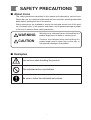
SAFETY PRECAUTIONS
■ About Icons
The safety precautions described in this manual are indicated by various icons.
Please be sure you read and understand the icons and their meanings described
below before reading the rest of the manual.
Safety precautions are intended to ensure the safe and correct use of this product, to prevent injury to the operator and others, and to prevent damage to property. Be sure to observe these safety precautions.
WARNING
Warnings are indicated when mishandling this
product might result in death or serious injury.
CAUTION
Cautions are indicated when mishandling this
product might result in minor injury to the user, or
only physical damage to the product.
■ Examples
Use caution when handling the product.
The indicated action is prohibited.
Be sure to follow the indicated instructions.
i
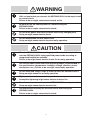
WARNING
Ground the FG (Frame Ground) terminal to a terminal resistance of
100Ω or less before you connect the SRF206/212/224 to the input circuit
or control circuit.
Failure to do so might cause electric shock or fire.
Be sure to turn the source power OFF before wiring the
SRF206/212/224.
Failure to do so might cause electric shock.
Do not touch power terminals and other electrically charged parts.
Doing so might cause electric shock.
Do not disassemble the SRF206/212/224.
Doing so might cause electric shock or faulty operation.
CAUTION
Wire the SRF206/212/224 according to predetermined standards. Also
wire the SRF206/212/224 using specified power leads according to
recognized installation methods.
Failure to do might cause electric shock, fire or faulty operation.
Use the SRF206/212/224 within the operating ranges recommended in
the specifications (temperature, humidity, voltage, vibration, shock,
atmosphere, etc.). Failure to do so might cause faulty operation.
Do not allow lead scraps, chips or water to enter the SRF206/212/224.
Doing so might cause fire or faulty operation.
Tighten the terminal screws to the specification torque.
Incomplete tightening might cause electric shock or fire.
Do not use unused terminals on the SRF206/212/224 as relay terminals.
Doing so might cause electric shock or fire.
We recommend attaching the terminal covers after wiring the
SRF206/212/224.
Failure to do so might cause electric shock.
ii
The Role of This Manual
In all, 2 manuals have been prepared for the SRF206/212/224. Read the manual according to your specific
requirements.
The following lists all the manuals that accompany the SRF206/212/224 and gives a brief outline of the manual:
If you do not have the required manual, contact Yamatake Corporation or your dealer.
Dot Printing Model Smart Recorder SRF206/212/224
Installation/Operation
Manual No.CP-SP-1027E
This manual is required reading for those who use the SRF206/212/224,
those who design hardware for integrating the SRF206/212/224 into
operator control panels, those who carry out maintenance, and those who
operate instruments in which the SRF206/212/224 is integrated. It outlines
the hardware configuration, product features and the other products used in
combination with the SRF206/212/224.
It also describes how to install and wire the SRF206/212/224 for integrating
into instruments, method of operation, maintenance and inspection,
troubleshooting, and hardware specifications.
DIGITRONIK CPL Communications Dot Printing Model
SRF206/212/224
Manual No.CP-SP-1028E
This manual.
This manual is required reading for those who use the CPL communication
functions of the SRF206/212/224.
It briefly describes CPL communications, how to wire the SRF206/212/224,
communication procedures, communication data for the SRF206/212/224,
troubleshooting and communication specifications.
iii
Organization of This User's Manual
This manual is organized as follows:
Chapter 1. COMMUNICATION FUNCTIONS
This chapter lists communication functions and model numbers of the
SRF206/212/224.
Chapter 2. WIRING
This chapter describes RS-232C and RS-485 wiring methods to make a
communication link between the SRF206/212/224 and other instruments.
Chapter 3. SETTINGS
This chapter describes SRF206/212/224 communication settings.
Chapter 4. COMMUNICATION PROCEDURE
This chapter describes communication procedures, message configuration, data
read/write and signal timing operations.
Chapter 5. COMMUNICATION DATA TABLE
This chapter provides various data tables for communications on the
SRF206/212/224.
Chapter 6. MAINTENANCE AND TROUBLESHOOTING
This chapter describes checkpoints to diagnose failures in SRF206/212/224
communications.
Chapter 7. SPECIFICATIONS
This chapter lists communication specifications for the SRF206/212/224.
Appendix
The appendix provides code tables and network configurations using the CMC10L
RS-232C/RS485 converter.
iv
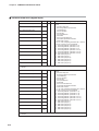
Contents
SAFETY PRECAUTIONS
Unpacking
The Role of This Manual
Organization of This User's Manual
Conventions Used in This Manual
Chapter 1.
COMMUNICATION FUNCTIONS
Chapter 2.
WIRING
2-1 RS-232C Connection • • • • • • • • • • • • • • • • • • • • • • • • • • • • • • • • • • • • • • • • • • • • • • • • • • • • • • • 2-1
2-2 RS-485 Connection • • • • • • • • • • • • • • • • • • • • • • • • • • • • • • • • • • • • • • • • • • • • • • • • • • • • • • • • 2-3
■ Connection with 5-wire system • • • • • • • • • • • • • • • • • • • • • • • • • • • • • • • • • • • • • • • • 2-3
■ 3-wire system used together • • • • • • • • • • • • • • • • • • • • • • • • • • • • • • • • • • • • • • • • • • • 2-4
2-3 RS-232C Models • • • • • • • • • • • • • • • • • • • • • • • • • • • • • • • • • • • • • • • • • • • • • • • • • • • • • • • • • • • 2-5
2-4 RS-485 Models • • • • • • • • • • • • • • • • • • • • • • • • • • • • • • • • • • • • • • • • • • • • • • • • • • • • • • • • • • • • • 2-6
Chapter 3.
SETTINGS
3-1 Communication Setup Items • • • • • • • • • • • • • • • • • • • • • • • • • • • • • • • • • • • • • • • • • • • • • • • 3-1
■ System Setup • • • • • • • • • • • • • • • • • • • • • • • • • • • • • • • • • • • • • • • • • • • • • • • • • • • • • • • • • • 3-1
3-2 Initial Setup • • • • • • • • • • • • • • • • • • • • • • • • • • • • • • • • • • • • • • • • • • • • • • • • • • • • • • • • • • • • • • • • 3-2
■ Station Address • • • • • • • • • • • • • • • • • • • • • • • • • • • • • • • • • • • • • • • • • • • • • • • • • • • • • • • • 3-2
■ Transmission Rate and Data Format • • • • • • • • • • • • • • • • • • • • • • • • • • • • • • • • • • • 3-2
Chapter 4.
COMMUNICATION PROCEDURE
4-1 Outline of Communication Procedure and Messages • • • • • • • • • • • • • • • • • • • • • • 4-1
■ Communication Procedure • • • • • • • • • • • • • • • • • • • • • • • • • • • • • • • • • • • • • • • • • • • • 4-1
■ Message Configuration • • • • • • • • • • • • • • • • • • • • • • • • • • • • • • • • • • • • • • • • • • • • • • • • 4-1
■ Examples • • • • • • • • • • • • • • • • • • • • • • • • • • • • • • • • • • • • • • • • • • • • • • • • • • • • • • • • • • • • • • 4-2
■ Data Address Concept • • • • • • • • • • • • • • • • • • • • • • • • • • • • • • • • • • • • • • • • • • • • • • • • • 4-2
4-2 Data Link Layer • • • • • • • • • • • • • • • • • • • • • • • • • • • • • • • • • • • • • • • • • • • • • • • • • • • • • • • • • • • • 4-3
■ Description• • • • • • • • • • • • • • • • • • • • • • • • • • • • • • • • • • • • • • • • • • • • • • • • • • • • • • • • • • • • • 4-3
4-3 Application Layer • • • • • • • • • • • • • • • • • • • • • • • • • • • • • • • • • • • • • • • • • • • • • • • • • • • • • • • • • • 4-6
■ Outline • • • • • • • • • • • • • • • • • • • • • • • • • • • • • • • • • • • • • • • • • • • • • • • • • • • • • • • • • • • • • • • • • 4-6
4-4 Data Read • • • • • • • • • • • • • • • • • • • • • • • • • • • • • • • • • • • • • • • • • • • • • • • • • • • • • • • • • • • • • • • • • • 4-7
■ Description of Read Instruction • • • • • • • • • • • • • • • • • • • • • • • • • • • • • • • • • • • • • • • • 4-7
■ Read Response • • • • • • • • • • • • • • • • • • • • • • • • • • • • • • • • • • • • • • • • • • • • • • • • • • • • • • • • 4-8
■ Decimal Numeric Expression (numeric data) • • • • • • • • • • • • • • • • • • • • • • • • • • 4-9
4-5 Data Write • • • • • • • • • • • • • • • • • • • • • • • • • • • • • • • • • • • • • • • • • • • • • • • • • • • • • • • • • • • • • • • • 4-10
■ Description of Write Instruction • • • • • • • • • • • • • • • • • • • • • • • • • • • • • • • • • • • • • • 4-10
■ Write Response • • • • • • • • • • • • • • • • • • • • • • • • • • • • • • • • • • • • • • • • • • • • • • • • • • • • • • • 4-11
v
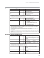
4-6 Termination Code Table • • • • • • • • • • • • • • • • • • • • • • • • • • • • • • • • • • • • • • • • • • • • • • • • • • 4-12
■ Normal and Abnormal Termination • • • • • • • • • • • • • • • • • • • • • • • • • • • • • • • • • • • 4-12
4-7 Timing Specifications • • • • • • • • • • • • • • • • • • • • • • • • • • • • • • • • • • • • • • • • • • • • • • • • • • • • 4-13
■ Timing Specifications for Instruction and Response Messages • • • • • • 4-13
■ RS-485 Driver Control Timing Specifications • • • • • • • • • • • • • • • • • • • • • • • • • 4-13
Chapter 5.
COMMUNICATION DATA TABLE
5-1 Basic Communication Data Processing • • • • • • • • • • • • • • • • • • • • • • • • • • • • • • • • • • • 5-1
■ Communication Data Types and Formats • • • • • • • • • • • • • • • • • • • • • • • • • • • • • • 5-1
■ Communication Data Storage Memory • • • • • • • • • • • • • • • • • • • • • • • • • • • • • • • • • 5-1
■ Data Address • • • • • • • • • • • • • • • • • • • • • • • • • • • • • • • • • • • • • • • • • • • • • • • • • • • • • • • • • • 5-2
■ Data Read/Write Count • • • • • • • • • • • • • • • • • • • • • • • • • • • • • • • • • • • • • • • • • • • • • • • • • 5-2
■ Data Unit and Decimal Point Position • • • • • • • • • • • • • • • • • • • • • • • • • • • • • • • • • • 5-2
5-2 Communication Data Table • • • • • • • • • • • • • • • • • • • • • • • • • • • • • • • • • • • • • • • • • • • • • • • • 5-3
■ Control Data • • • • • • • • • • • • • • • • • • • • • • • • • • • • • • • • • • • • • • • • • • • • • • • • • • • • • • • • • • • 5-3
■ Process Data Area • • • • • • • • • • • • • • • • • • • • • • • • • • • • • • • • • • • • • • • • • • • • • • • • • • • • • 5-6
■ Event Data • • • • • • • • • • • • • • • • • • • • • • • • • • • • • • • • • • • • • • • • • • • • • • • • • • • • • • • • • • • • • 5-7
■ Digital I/O Area (data area) • • • • • • • • • • • • • • • • • • • • • • • • • • • • • • • • • • • • • • • • • • • • 5-8
■ Common Data Area (common setup items) • • • • • • • • • • • • • • • • • • • • • • • • • • 5-10
■ Common Data Area (schedule demand printing) • • • • • • • • • • • • • • • • • • • • 5-12
■ Common Data Area (messages) • • • • • • • • • • • • • • • • • • • • • • • • • • • • • • • • • • • • • 5-13
■ Common Data Area (digital input) • • • • • • • • • • • • • • • • • • • • • • • • • • • • • • • • • • • 5-14
■ Common Data Area (digital output) • • • • • • • • • • • • • • • • • • • • • • • • • • • • • • • • • • 5-15
■ Common Data Area (user functions) • • • • • • • • • • • • • • • • • • • • • • • • • • • • • • • • • 5-16
■ Common Data Area (copy) • • • • • • • • • • • • • • • • • • • • • • • • • • • • • • • • • • • • • • • • • • • 5-17
■ Common Data Area (extended setup) • • • • • • • • • • • • • • • • • • • • • • • • • • • • • • • • 5-17
■ Segment Table Area • • • • • • • • • • • • • • • • • • • • • • • • • • • • • • • • • • • • • • • • • • • • • • • • • • 5-18
■ Channel-independent (range) • • • • • • • • • • • • • • • • • • • • • • • • • • • • • • • • • • • • • • • • 5-21
■ Channel-independent (calculation) • • • • • • • • • • • • • • • • • • • • • • • • • • • • • • • • • • 5-23
■ Channel-independent (scale) • • • • • • • • • • • • • • • • • • • • • • • • • • • • • • • • • • • • • • • • 5-24
■ Channel-independent (event) • • • • • • • • • • • • • • • • • • • • • • • • • • • • • • • • • • • • • • • • 5-25
■ Communication Data Area • • • • • • • • • • • • • • • • • • • • • • • • • • • • • • • • • • • • • • • • • • • • 5-26
■ Bitmap Data • • • • • • • • • • • • • • • • • • • • • • • • • • • • • • • • • • • • • • • • • • • • • • • • • • • • • • • • • • • 5-27
■ Range Code Tables • • • • • • • • • • • • • • • • • • • • • • • • • • • • • • • • • • • • • • • • • • • • • • • • • • • 5-30
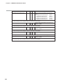
Chapter 6.
MAINTENANCE AND TROUBLESHOOTING
■ Check Items in Case Communication is Disabled • • • • • • • • • • • • • • • • • • • • • • 6-1
Chapter 7.
SPECIFICATIONS
■ RS-232C Specifications • • • • • • • • • • • • • • • • • • • • • • • • • • • • • • • • • • • • • • • • • • • • • • • • 7-1
■ RS-485 Specifications • • • • • • • • • • • • • • • • • • • • • • • • • • • • • • • • • • • • • • • • • • • • • • • • • • 7-1
vi
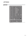
APPENDIX
■ Code Table • • • • • • • • • • • • • • • • • • • • • • • • • • • • • • • • • • • • • • • • • • • • • • • • • • • • • • • • • App.-1
■ SRF Character Code Table • • • • • • • • • • • • • • • • • • • • • • • • • • • • • • • • • • • • • • • • • App.-2
■ Connection With CMC10L • • • • • • • • • • • • • • • • • • • • • • • • • • • • • • • • • • • • • • • • • • App.-3
Conventions Used in This Manual
The following conventions are used in this manual:
Handling Precaution
: Handling Precautions indicate items that the user should pay attention to
when handling the xxx.
Note
(1), (2), (3)
: Notes indicate useful information that the user might benefit by knowing.
: The numbers with the parenthesis indicate steps in a sequence or
indicate corresponding parts in an explanation.
vii
Chapter 1.
COMMUNICATION FUNCTIONS
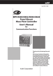
• On a system operating on the RS-232C interface, a master station (a host computer, usually a PC) is connected to
the instrument in a point-to-point configuration. At this time, only one instrument can communicate with the
master station using a preset station address.
• On a system operating on the RS-485 interface, up to 31 instruments (see *1) can be connected to a master
station. Station addresses are then used to identify other stations for communication.
• The communication protocol and format conform to the RS-232C and RS-485 interfaces.
• When the following procedure is established during communication, instrument data can be read or written:
1. The master station (host computer) transmits a request message to the slave station.
2. The master station receives a response message from the slave station.
• The master station issues two types of requests to a slave station: read and write.
• The type of read/write data can be optionally selected with a data address.
• CPL (Controller Peripheral Link) Communications isYamatake host communication protocol.
RS-232C connection example
Master station
RS-232C
RS-485 connection example
RS-485 connection example
Master station
Master station
RS-232C
RS-232C
RS-232C/RS-485 converter
RS-485 (5-wire system)
Slave
station
CMC10L001A000
*2
RS-485 (35-wire system)
Slave
station
Slave
station
Connection between master station
and slave station
Connection between master station
and slave station
• The high-performance communication controller CMC10L is available for conversion between the RS-232C and
RS-485 interfaces.
*1 : When the master station is an MA500 DIM or CMC10L, it can be connected to up to 16 slave stations.
*2 : The communication adapter CMC10L is an RS-232C/RS-485 converter available from Yamatake .
1-1
Chapter 2.
2 - 1
WIRING
RS-232C Connection
WARNING
Ground the FG (Frame Ground) terminal to a terminal resistance of
100Ω or less before you connect the SRF206/212/224 to the input circuit
or control circuit.
Failure to do so might cause electric shock or fire.
Be sure to turn the source power OFF before wiring the SRF206/212/224.
Failure to do so might cause electric shock.
Do not touch power terminals or other electrically charged parts.
Doing so might cause electric shock.
CAUTION
Wire the SRF206/212/224 according to predetermined standards. Also
wire the SRF206/212/224 using specified power leads according to
recognized installation methods.
Failure to do might cause electric shock, fire or faulty operation.
Do not allow lead scraps, chips or water to enter the SRF206/212/224.
Doing so might cause fire or faulty operation.
Tighten the terminal screws to the specification torque.
Incomplete tightening might cause electric shock or fire.
Do not use unused terminals on the SRF206/212/224 as relay terminals.
Doing so might cause electric shock or fire.
We recommend attaching the terminal covers after wiring the
SRF206/212/224.
Failure to do so might cause electric shock.
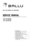
An SRF206/212/224 supporting an RS-232C communication function is wired for communication as shown
below.
• Communication with the master station in a point-to-point configuration
The SRF206/212/224 is provided with three communication terminals (RD,
SD and SG). Data may not be output unless the other terminals of the master
station RS-232C interface are short-circuited as shown in figure on the next
page.
Usually, the pin array of the RS-232C connector of a PC is as shown in the
figure on the next page (terminal mode). The locations of pins SD and RD, RS
and CS and DR and ER may be reversed (MODEM mode), but this is rare.
Check the RS-232C pin array in the host computer instruction manual.
2-1
Chapter 2. WIRING
RD
SD
SG
RS
CS
DR
CD
ER
SD
RD
2
3
SG
5
7
8
6
1
4
Host computer (master station)
DIGITRONIK control (slave station)
Example of connection using
Yamatake CBL232FNZ02
Note
Cable model No.
●
: CBL232FNZ02
(2m cable for RS-232C, 9pin D-Sub socket↔contact-crimptype terminal lug)
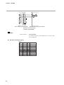
RS-232C connector signals
9 pins
Pin No. JIS Code Name
2-2
Signal Direction
Host-station
1
CD
DCD
←
2
RD
RxD
←
3
SD
TxD
→
4
ER
DTR
→
5
SG
GND
6
DR
DSR
←
7
RS
RTS
→
8
CS
CTS
←
Chapter 2. WIRING
2 - 2
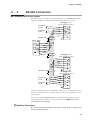
RS-485 Connection
■ Connection with 5-wire system
The following is an example of a system connection of a DIGITRONIK control
supporting the RS-485 communication function using the 5-wire system:
Terminating
resistor
DIGITRONIK control
or
5-wire system(slave station)
SDA
SDB
Terminating
resistor
RDA
RDB
SG
Shielded cable
FG
Master station
RDA
RDB
SDA
SDB
SG
FG
Shielded
cable
DIGITRONIK control
or
5-wire system(slave station)
SDA
SDB
RDA
RDB
SG
FG
Shielded cable
DIGITRONIK control
or
5-wire system(slave station)
SDA
Terminating
resistor
Terminating
resistor
SDB
RDA
RDB
SG
FG
Connect a terminating resistor of 150Ω±5%, 1/2W min. to the instrument at each
end of the transmission line. Connect only one end of the shielded wire to the
frame ground.
Other 3-wire system DIGITRONIK units of Yamatake can be used on the same
communication line. Conduct the wiring shown at the item "■ 3-wire system
used together" on next page.
Handling Precautions
Be sure to connect SG terminals each other. Failure to do so might cause
unstable communications.
2-3
Chapter 2. WIRING
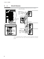
■ 3-wire system used together
An SRF206/212/224 supporting the RS-485 communication function can also be
used in a 3-wire system. The following is an example of such a connection:
DIGITRONIK control
or
5-wire system (slave station)
Terminating
resistor
SDA
SDB
*
*
RDA
RDB
SG
FG
Master station
RDA
Shielded
cable
RDB
SDA
SDB
*
*
SG
FG
Shielded
cable
3-wire system (slave station)
DA
DB
SG
FG
Shielded
cable
DIGITRONIK control
or
5-wire system (slave station)
SDA
Terminating
resistor
SDB
*
*
RDA
RDB
SG
FG
Connect one terminating resistor of 150Ω±5%, 1/2W min. to the instrument at
each end of the transmission line. Connect only one end of the shielded wire to the
frame ground.
(*) must be wired externally.
On 3-wire system, the CMC10L001A000 of Yamatake can be used as a coverter
for master station.
See, "■ Connection with CMC10L" (Page App.-3) for details.
Handling Precautions
Be sure to connect SG terminals each other. Failure to do so might cause
unstable communications.
2-4
Chapter 2. WIRING
2 - 3
RS-232C Models
The communication terminal array of an RS-232C model supporting the communication function is as follows:
1
2
N
1
11
2
12
22
3
13
23
4
14
24
5
15
25
6
16
26
7
17
27
8
18
28
9
19
29
10
20
30
21
3
Communication
terminals
Option unit 1
RS-232C
(Yamatake CPL communications)
SD
RD
SG
9
19
29
10
20
30
Connection example :
RD
SD
SG
RS
CS
DR
CD
ER
2
3
5
SD
RD
SG
7
8
6
1
4
Host computer (master station)
DIGITRONIK control (slave station)
Note
Cable model No. : CBL232FNZ02
(2m cable for RS-232C, 9pin D-Sub socket contact-crimptype terminal lug)
2-5
Chapter 2. WIRING
2 - 4
RS-485 Models
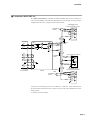
The communication terminal array of an RS-485 model supporting the communication function is as follows:
Connection example:
DIGITRONIK control (slave station)
1
2
N
1
11
Terminating
resistor
21
2
12
22
3
13
23
4
14
24
5
15
25
6
16
26
7
17
27
8
18
28
9
19
29
10
20
30
SDA
SDB
RDA
RDB
SG
Terminating
resistor
3
FG
Shielded cable
Master station
Communication
terminals
RDA
RDB
SDA
SDB
SG
FG
Option unit 1
Shielded cable
DIGITRONIK control (slave station)
SDA
SDB
RDA
RDB
SG
RS-485
(Yamatake CPL communications)
SDA
SDB
SG
FG
Shielded cable
9
19
29
10
20
30
(internally
connected
at terminal)
RDB
RDA
Terminating
resistor
Terminating
resistor
DIGITRONIK control (slave station)
SDA
SDB
RDA
RDB
SG
FG
Connect a terminating resistor of 150Ω±5%, 1/2W min. to the station at each end
of the transmission line. Connect only one end of the shielded wire to the frame
ground.
2-6
Chapter 3.
3 - 1
SETTINGS
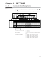
Communication Setup Items
■ System Setup
Communication setup items are displayed in system setup screen Nos. “ ”, “ ”
and “ ”.
These setup items are not displayed on models that do not support the communications option.
LOCK
EVNT
CLK
RNG
COPY
SPD
SYS
SCL
CH
EVNT
Display No.
DATA
Description
Configuration lock
List printing ON/OFF
Menu level
Recording format
Recorder ID No.
Recording time ON/OFF
Scale recording ON/OFF
Recording color selection
Communication access rights
Station address
Communications method
Extended menu entry
Setup Details
Communication access rights
: “1” read only
“2” read/write
Station address
: “0 to 127”. Communication is inhibited when set
to “0”.
Communication method
: “1” 4800bps, 8bits, even parity, 1 stop bit
“2” 4800bps, 8bits, no parity, 2 stop bits
“3” 9600bps, 8bits, even parity, 1 stop bit
“4” 9600bps, 8bits, no parity, 2 stop bits
3-1
Chapter 3. SETTINGS
3 - 2
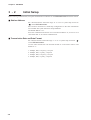
Initial Setup
Before starting communication, set up the communication conditions for the SRF206/212/224 and master station.
■ Station Address
Set a decimal numeric within the range “0” to “127” to system setup screen No.
“ ” on the SRF206/212/224.
Slave stations connected in a multi-drop configuration on the same transmission
line in an RS-485 system must have unique addresses.
The default address is “0”.
Since the communication function is not activated at address “0”, be sure to set a
value other than “0” to execute communication.
■ Transmission Rate and Data Format
Set a decimal numeric within the range “1” to “4” to system setup screen No. “ ”
on the SRF206/212/224.
Use the same transmission rate and data format as on the master station. The
default is “1”.
1:
2:
3:
4:
3-2
4800bps, 8bits, even parity, 1 stop bit
4800bps, 8bits, no parity, 2 stop bits
9600bps, 8bits, even parity, 1 stop bit
9600bps, 8bits, no parity, 2 stop bits
Chapter 4.
4 - 1
COMMUNICATION PROCEDURE
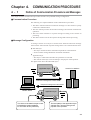
Outline of Communication Procedure and Messages
This chapter outlines communication procedures and the concept behind message configuration.
■ Communication Procedure
The following is a simple breakdown of the communication procedure:
1. The master station transmits an instruction message to a slave station to specify
a station for communication.
2. The slave station processes the instruction message, and executes read and write
operations.
3. The slave station transmits a response message according to the contents of
processing.
4. The master station receives the response message and executes processing.
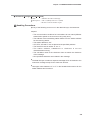
■ Message Configuration
A message consists of two layers as shown below. Both the instruction message
from a master station and the response message from a slave station take this form.
●
Data link layer
• This layer contains the basic information required for communication.
• It also contains message destination and check information.
●
Application layer
• This layer is where data read and write operations are executed.
• The content of this layer varies according to the purpose of the operation.
The figure below shows the individual layers.
Application layer
A total of 31 stations
Data link layer
Instruction message from master station
Response message from slave station
Slave stations
Master station
Application layer
Data link layer
The driver of the data link layer knows:
¥ Destination (station address)
¥ Load check sheet (checksum)
The load (data) of the application layer
changes every time according to the
purpose of the operation.
4-1
Chapter 4. COMMUNICATION PROCEDURE
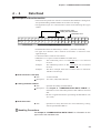
■ Examples
Messages have the following structure:
● Read instruction
・Instruction message
STX
0
1
0
0
X
R
S
,
1
Data link layer
0
0
1
W
,
2
ETX
Application layer
9
A
CR
LF
Data link layer
・Response message
STX
0
1
0
0
X
0
0
Data link layer
,
0
,
4
2
ETX
9
4
CR
LF
Data link layer
Application layer
● Write instruction
・Instruction message
STX
0
1
0
0
X
W
S
,
Data link layer
1
0
0
1
W
Application layer
,
5
8
ETX
5
A
CR
LF
Data link layer
・Response message
STX
0
1
0
Data link layer
0
X
0
0
ETX
Application layer
8
2
CR
LF
Data link layer
The following sections describe in detail the data link layer and application layer:
■ Data Address Concept
The SRF206/212/224 uses “data addresses” to read and write data. Data
addresses allow data to be written and read to and from a corresponding address
for the data.
Data A
Data B
Data C
:
501W
502W
503W
:
See Chapter 5. “COMMUNICATION DATA TABLE” for information on the
relationship between data and address.
4-2
Chapter 4. COMMUNICATION PROCEDURE
4 - 2
Data Link Layer
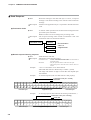
■ Description
• The data link layer contains eight types of basic message transmission information.
• The instruction message and response message have the same structure in the
data link layer.
ETX
Checksum
The underlined SRF200
parameters ( ) are set
to fixed values.
STX
Station address
Subaddress
Device ID code
CR
LF
02H 30H 41H 30H 30H 58H 52H 53H 2CH 31H 30H 30H 31H 57H 2CH 32H 03H 38H 41H 0DH 0AH
STX
0
A
0
0
X
R
S
Data link layer
,
1
0
0
1
W
,
2
ETX
Application layer
8
A
CR
LF
Data link layer
The following describes each function of the data link layer:
● STX (Start of TeXt)
◆ Role
: Indicates the beginning of a message.
Description • Fixed at 02H.
• When the instrument receives an STX, it is identified as the first
character of a new instruction message regardless of location
with a message.
● Station address
◆ Role
: Specifies the destination station, and allows communication with
the specified station.
Description • If “0” is set as the station address, the communication function is
stopped.
So, to enable communication be sure to set an address value of
“1” or more.
• Two hexadecimal characters. For details, see the example.
• See Chapter 3. “SETTINGS” for information on station
address settings.
Example
: When the station address of the other instrument is “10”:
1. 10 (decimal) = 0AH (hexadecimal)
2. This can be converted into character codes:
0 = 30H, A = 41H
3. “0A” (30H, 41H) calculated in example 2 is used as the
station address.
Handling Precautions
Note that the function of the station address differs entirely from that of the
data address of the application layer.
● Subaddress
Description
: The subaddress is meaningless on the SRF206/212/224.
Be sure to set a subaddress of “00” (30H, 30H) that has the same
format as the station address.
● Device ID code
Description
: Only character codes “X” (58H) or “x” (78H) can be set on the
SRF206/212/224.
4-3
Chapter 4. COMMUNICATION PROCEDURE
● ETX (End of TeXt)
◆ Role
: Indicates the end of the application layer.
Description : Fixed at 03H.
● Checksum
◆ Role
: A value to be used to check whether or not a message has been
corrupted by an error (such as noise) during communication.
Description • Two hexadecimal characters.
• This function operates as follows:
1. Add one byte each to the character codes of the message from
STX to ETX.
2. Derive the two’s complement of the result of this addition.
3. Convert the result into character codes.
Example
: The instruction message on the preceding page is used in the
following example:
1. Add one byte each to the character codes from STX to ETX.
The lower-order one byte of the calculation result is 76H.
2. The result of two’s complement addition is 8AH.
3. 85H is converted into character codes and used as the
checksum value. The result is “8A”, (38H) and (41H).
See the station address example (on the preceding page) for
information on character code conversion.
Handling Precautions
The checksum in the instruction message can be omitted, but no
checksum is then included in the response message. The checksum
function should not be omitted to ensure proper message reception and
transmission.
4-4
Chapter 4. COMMUNICATION PROCEDURE
● CR and LF (Carriage Return/Line Feed)
◆ Role
: Indicates the end of a message.
Description • “CR” is (0DH), and “LF” is (0AH).
• Be sure to use CR and LF in pair.
Handling Precautions
●
If any of the following errors occur in the data link layer, the instrument
respond:
• The communication conditions for both stations do not match (different
transmission speeds or the occurrence of a parity error).
• The address of the transmitting station differs from the station address
for the receiving station.
• The station address is “00”.
• STX, ETX, CR and LF are not placed at the specified positions.
• The device ID code is neither “X” nor “x”.
• The station address, subaddress or checksum is not two
charactersdoes not long.
• The calculation result of the checksum does not match the checksum
of the message.
• Non-specified characters are included in the message.
●
The data link layer contains a response message which is identical to the
instruction message except for the checksum function.
●
Use upper-case characters “A” to “F” in the hexadecimal numerics for the
station address and checksum.
4-5
Chapter 4. COMMUNICATION PROCEDURE
4 - 3
Application Layer
■ Outline
• The application layer contains instructions, data, data count and termination
code.
• In the application layer, the instruction message and response message have a
different structure.
• There are two types of instruction messages: read instructions and write
instructions. Each of these instruction messages have their own responses.
• A termination code indicates how an instruction message has been processed.
Application layer
Instruction
message
Read instruction
Instruction code (RS)
Leading data address
Read data count
Write instruction
Instruction code (WS)
Leading data address
Write data
Response
message
Read response
Termination code
Read data
Write response
4-6
Termination code
Chapter 4. COMMUNICATION PROCEDURE
4 - 4
Data Read
■ Description of Read Instruction
• This instruction permits the contents of continuous data addresses starting from
the specified leading read data address to be read in one message.
• The application layer of a read instruction consists of the following three types
of data:
Read instruction code
Leading read data address
Read data count
02H 30H 31H 30H 30H 58H 52H 53H 2CH 31H 30H 30H 31H 57H 2CH 32H 03H 39H 41H 0DH 0AH
STX
0
1
0
0
X
R
Data link layer
S
,
1
0
0
1
W
,
Application layer
2
ETX
9
A
CR
LF
Data link layer
• Individual data items are delimited by a comma “,” (character code 2CH).
• An upper-case character code is used for each numeric or character in the
application layer.
• A decimal number is used for each numeric.
• Additional “0”s or spaces cannot be added to each data item.
Example
: The underlined portion of “RS,01001W,2” is not allowed
incorrect.
Example
: The underlined portions of “RS, 1001W,02” are not allowed
incorrect.
Example
: The above example shows that two-data items are read from
1001W as one message.
● Read instruction code (RS)
◆ Role
: A read command
Description : Two “RS” (52H, 53H) characters
● Leading read data address
◆ Role
: Specifies the leading read data address.
Description • See Chapter 5. “COMMUNICATION DATA TABLE” for
information on the relationship between data addresses and read
data.
• Be sure to append the numeric representing the data address with
“W” (57H).
● Read data count
◆ Role
: Specifies how many data items are read continuously, starting
with the specified data address.
Handling Precautions
See Chapter 5.“COMMUNICATION DATA TABLE” for information on the
upper limit of the read data count.
4-7
Chapter 4. COMMUNICATION PROCEDURE
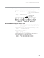
■ Read Response
◆ Role
: When the message in the data link layer is correct, a response
message is sent back according to the contents of the instruction
message.
Description : All data in the application layer is expressed in decimal character
code.
● Termination Code
◆ Role
: A numeric which specifies how the instruction message has been
processed by the instrument.
Different values are set according to the processing result.
Description : The response message must include a termination code. The
termination codes are classified as follows:
Termination code
Normal
* The termination
code is a
2-digit decimal.
Warning
Abnormal
● Normal response/warning response
◆ Role
: Sends back the read data.
Description : Information in the application layer
• Termination code
: See 4-6 “Termination Code Table” for information on
termination codes.
: Only the specified number of data items are input.
: The decimal point is removed from a numeric when it is
entered.
• Read data
Example
: “55.6” is converted to “556” when entered.
: Individual data items are delimited by a comma “,”(2CH).
: The range and number of digits of each data item depend upon
the read data.
: A normal response (when two data items are read properly)
Example
Termination code (00 = normal)
Read data
02H 30H 31H 30H 30H 58H 30H 30H 2CH 31H 32H 33H 2CH 38H 37H 30H 03H 46H 35H 0DH 0AH
STX
0
1
0
0
X
0
0
,
1
2
3
,
8
7
0
ETX
Application layer
Data link layer
Example
F
5
: A warning response (❈❈ indicates the warning code numeric.)
02H 30H 31H 30H 30H 58H ❈H ❈H 2CH 30H 2CH 38H 37H 30H 03H ??H ??H 0DH 0AH
0
1
0
0
Data link layer
4-8
X
❈
LF
Data link layer
Termination code (❈❈ = warning)
Read data
STX
CR
❈
,
0
,
8
Application layer
7
0
ETX
?
?
CR
Data link layer
LF
Chapter 4. COMMUNICATION PROCEDURE
● Abnormal response
◆ Role
: Indicates that there is an abnormality in an instruction message,
which contains no data and cannot be normally read.
Description : Information in the application layer
Termination code
: Indicates an abnormality type.
: See 4-6 “Termination Code Table”
for details.
Example
: An abnormal response
Termination code
(❈❈ = error)
02H 30H 31H 30H 30H 58H ❈H ❈H 03H ??H ??H 0DH 0AH
STX
0
1
0
0
Data link layer
X
❈
❈
ETX ??
Application layer
??
CR
LF
Data link layer
■ Decimal Numeric Expression (numeric data)
◆ Role
: All the numerics, read count, write value (see the description of
the WS command) and read data in the data address follow the
rules given below.
(1) When a numeric is negative, prefix the numeric with a minus sign “-” (2DH).
Example
: “-123” (2DH, 31H, 32H, 33H)
(2) When a numeric is “0”, use one “0”.
Example
: “0” (30H)
Example
: “00” (30H, 30H) is not allowed.
(3) When a numeric is positive, never prefix the numeric with a plus sign “+”.
(4) Never add additional “0”s or spaces before a numeric.
Example
: “0123” (30H, 31H, 32H, 33H) is not allowed.
Example
: “ 123” (20H, 31H, 32H, 33H) is not allowed.
4-9
Chapter 4. COMMUNICATION PROCEDURE
4 - 5
Data Write
■ Description of Write Instruction
• This instruction permits the contents of continuous data addresses starting with
the specified leading write data address to be simultaneously written in one
message.
• The application layer of a write instruction consists of the following three types
of data:
Write instruction code
Write data (1st data item)
Leading write data address Write data (2nd data item)
02H 30H 31H 30H 30H 58H 57H 53H 2CH 31H 30H 30H 31H 57H 2CH 32H 2CH 36H 35H
STX
0
1
0
0
X
W
Data link layer
S
,
1
0
0
1
W
,
2
,
6
5
Application layer
03H 46H 45H 0DH 0AH
ETX
F
E
CR
LF
Data link layer
• Individual data items are delimited with a comma “,” (character code 2CH).
• The write data count need not be specified.
• An upper-case character code is used for each numeric or character in the
application layer.
• A decimal number is used for each numeric.
• Additional “0”s (30H) or spaces cannot be added to each data item.
Example
Example
Example
: The underlined portion of “WS,01001W,2” is not allowed.
: The underlined portions of “WS, 1001W,02” are not allowed.
: The above example shows that “2” and “65” are written at
address 1001W and 1002W in one message.
● Write instruction code (WS)
◆ Role
: A write command
Description : Two “WS” (57H, 53H) characters
● Leading write data address
◆ Role
: Specifies the leading write data address.
• See Chapter 5. “COMMUNICATION DATA TABLE” for
information on the relationship between data addresses and write
data.
• Be sure to append the numeric representing the data address with
“W” (57H).
● Write data
◆ Role
: Data to be written to continuous addresses starting with the
specified data address.
Description • The range of a numeric to be written differs according to each
data address.
• Individual data are delimited by a comma “,” (2CH).
• The data address at which the corresponding data is written is
incremented by 1 sequentially, starting with the leading data
address (see the example given on the preceding page).
• The number of data item which can be written in one message is
limited. See Chapter 5. “COMMUNICATION DATA
TABLE” for details.
4-10
Chapter 4. COMMUNICATION PROCEDURE
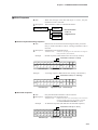
■ Write Response
◆ Role
: When the message in the data link layer is correct, only the
termination code is sent back.
Description : The termination codes are classified as follows:
Termination code
Normal
* The termination
code is a
2-digit decimal.
Warning
Abnormal
● Normal response/warning response
◆ Role
: Returns how the write instruction message has been processed.
Only a normal termination code or warning termination code is
returned.
Description : Information in the application layer
Termination code
Example
: A numeric specifying how the instruction message has
been processed by the instrument.
: Normal response (when all data items are correctly written)
Termination code (00 = normal)
02H 30H 31H 30H 30H 58H 30H 30H 03H 38H 32H 0DH 0AH
STX
0
1
0
0
Data link layer
Example
X
0
0
ETX
Application layer
8
2
CR
LF
Data link layer
: A warning response (❈❈ indicates the warning code numeric.)
Termination code (❈❈ = warning)
02H 30H 31H 30H 30H 58H ??H ??H 03H ??H ??H 0DH 0AH
STX
0
1
0
0
Data link layer
X
❈
❈
ETX
Application layer
?
?
CR
LF
Data link layer
● Abnormal response
◆ Role
: Only the abnormal termination code is returned.
Description : Information in the application layer
Termination code
Example
: Indicates that there is an abnormality in the instruction
message, and that write processing cannot be executed.
See 4-6 “Termination Code Table” for details.
: An abnormal response (❈❈ indicates an abnormal response.)
Termination code (❈❈ = error)
02H 30H 31H 30H 30H 58H ❈H ❈H 03H ??H ??H 0DH 0AH
STX
0
1
0
0
Data link layer
X
❈
❈
ETX
?
?
CR
LF
Application layer Data link layer
4-11
Chapter 4. COMMUNICATION PROCEDURE
4 - 6
Termination Code Table
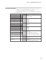
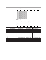
■ Normal and Abnormal Termination
Type
Response
Code
Description
Reason for Occurrence
Read Data
Normal
00
Normal termination
Command has been processed normally.
Present
Abnormal
99
Command error
Undefined command has been received.
Not present
Abnormal
40
Format error
CPL application error
Not present
Abnormal
41
Data item number error
Too many or too few read data items
Not present
Abnormal
42
Address range error
Write address contains access inhibit flag.
—
Abnormal
43
Numeric abnormality
error
Write data whose value is not within range
-32768 to +32767 is included.
—
Abnormal
44
Numeric value range
abnormal error
Write data other than the specified value is
included.
—
Warning
46
Write inhibit status error
The write command was received in a write
inhibit status.
—
Warning
81
Write inhibit data error
Write address contains a read-only address or an
address relating to an unmounted channel.
—
Warning
30
Instrument control error
A nonexecutable control command has been
received.
—
Warning
31
Write busy error
The write command was received during writing
on the instrument.
—
* A “nonexecutable control command” is a control command that cannot be
executed depending to the operating status of the recorder such as a feed request
issued during printing.
* When two or more errors occur simultaneously, the response code having the
higher priority is returned first.
4-12
Chapter 4. COMMUNICATION PROCEDURE
4 - 7
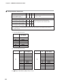
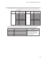
Timing Specifications
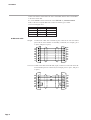
■ Timing Specifications for Instruction and Response Messages
When a slave station is connected with the master station directly via the RS-232C
interface, the following precautions regarding the transmission timing of
instruction messages from the master station and response messages from the slave
station should be observed:
● Response time-out
The maximum response time from the end of the instruction message transmission
by the master station until when the master station receives a response message
from the slave station is one second ((1) in figure). So, the response time-out
should be set to one second.
Generally, when a response time-out occurs, the instruction message is resent.
For details, see Chapter 6. “COMMUNICATION PROGRAM FOR MASTER
STATION.”
● Transmission start time
A wait time of 10ms or more is required before the master station starts to transmit
the next instruction message (to the same slave station or a different slave station)
after the end of receiving a response message ((2) in figure).
RS-485 3-wire system
Transmission
line
(1)
Instruction
message
(2)
RS-485 5-wire system and RS-232C
(1)
Master station,
transmission line
Instruction
message
Response
message
Response
message
(2)
Instruction
message
Instruction
message
Slave station,
transmission line
Response
message
Response
message
(1) End of master station transmission - Transmission start time of slave station = 1s max.
(2) End of slave station transmission - Transmission start time of master station = 10ms min.
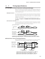
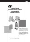
■ RS-485 Driver Control Timing Specifications
When the transmission/reception on the RS-485 3-wire system is directly
controlled by the master station, care should be paid to the following timing:
(1)
Master station
Driver control
(enable)
Transmission line
Slave station
Driver control
(4)
(disable)
Effective
data
Effective
data
(instruction message)
(response message)
(disable)
(enable)
(2)
End of master station
transmission
(3)
End of slave station
transmission
(1) End of master station transmission - Driver disable time = 500 s max.
(2) End of slave station reception - Driver enable time = 1ms min.
(3) End of slave station transmission - Driver disable time = 10ms max.
(4) End of master station reception - Driver enable time = 10ms min.
4-13
Chapter 5.
5 - 1
COMMUNICATION DATA TABLE
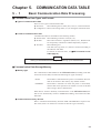
Basic Communication Data Processing
■ Communication Data Types and Formats
● Types of communication data
There are two types of communication data:
● Run status:
Data indicating the run status (PV, event, etc.) of the instrument.
● Configuration: Data (event setting values, etc.) for setting the instrument status.
● Format of communication data
Communication data is classified into the following formats:
● Numeric data: Data indicating a numeric value (PV, etc.).
● Bit data:
Data where each bit is significant (alarms, etc.). Bit data must
be composed by transmission and decomposed by reception.
● Text data:
Data indicating text.
Text data (unit, tag name, etc.) must be converted according to
the character code table.
For details on character data, see ■SRF Character Code
Table (App.-2).
IMPORTANT
Writing to EEPROM addresses is guaranteed only up to 100,000 times.
■ Communication Data Storage Memory
● Memory type
The communication data handled on the SRF206/212/224 (excluding some data
items such as time data) is stored in the following two types of memory:
• RAM:
• EEPROM:
Stored data is cleared when the power is turned OFF. However
data can be written to this memory any number of times.
Stored data is retained even when the power is turned OFF,
whereas data write operations are limited to a total of 100,000
times owing to device characteristics.
When data is written to RAM by communications on the SRF206/212/224, the
data is also automatically written to EEPROM excluding control data and other
data items.
● Communication memory devices
Data is transferred automatically between RAM and EEPROM as required. For
this reason, there is no need to be conscious of these two types of memory.
5-1
Chapter 5. COMMUNICATION DATA TABLE
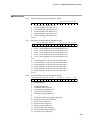
■ Data Address
The data addresses are allocated as in the table below.
Communication Data
Address
Control data
300 to 399
Process data
400 to 449
Event data
450 to 499
Digital I/O
500 to 599
Common data
600 to 999
Segment table data
1000 to 1099
Channel data
nn00 to nn99 *
Communication data
3500 to 3999
* Address “nn” is a value obtained by adding “10” to channels “1” to “24”.
For example, “nn” becomes “11” in the case of channel 1.
■ Data Read/Write Count
The number of data items that can be read and written continuously in a single
communication operation is determined within a range in which the command
frame length is less than 256bytes.
Data in the continuous data that does not exist due to differences in model Nos. is
handled as follows:
• Reading: “0” is read as dummy data (warning response is returned).
• Writing: Data is not written (warning response is returned).
Handling Precautions
Command frames up to 256bytes in length sometimes cannot be handled
depending on the hardware and software of the master station in use. (For
example, N88 BASIC can handle only up to 255bytes.) If this happens,
limit the command frame length to match the limitations of the master
station.
■ Data Unit and Decimal Point Position
Read/write data is not appended with a decimal point.
The unit and decimal point position is determined for each data item.
For details on the data unit and decimal point position, see the SRF206/212/224
Installation/Operation Manual.
Example:
Let’s assume that the data to be read and written is numeric data “105”. The data
unit and decimal point position is automatically determined by the data address
and instrument setup items.
So, the numeric data “105” can have various meaning such as 10.5% and 105°C
depending on the data address to be read and written.
5-2
Chapter 5. COMMUNICATION DATA TABLE
5 - 2
Communication Data Table
The address and read/write (R/W) enable status of each data item to be determined are shown in the table below.
Meaning of R/W column symbol
R/W enabled
X R/W disabled
«
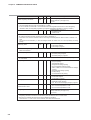
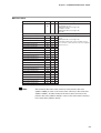
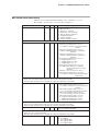
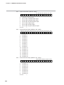
■ Control Data
Item
Recording start/stop
Address
R
W
300
X
«
Meaning of Data
Starts/stops recording.
0: Stop recording
1: Start recording
• If “1” is written before a complete recording stop status (wire dot head is at home position) after “0” is written,
response code 30 is returned.
• If a write is carried out during chart feeding, response code 30 is returned.
• If “1” is written during printing, the recording standby status is entered, and recording is resumed when
printing ends.
If “1” is written during recording standby, response code 30 is returned.
• An error response is not returned even if “1” is written in a recording start status.
Demand printing start/stop
301
X
«
Starts/stops demand printing.
0: Stop demand printing
1: Start demand printing
• If “1” is written during printing or chart feeding, response code 30 is returned.
List printing start/stop
302
X
«
Starts/stops list printing.
0: Stop list printing
1: Start specified list printing
2: Start range/scale settings printing
3: Start event and DI/DO settings printing
4: Start MSG, S.DMD, UF and communications
settings printing
5: Start segment table settings printing
6: Start all list printing
7: Start communications list printing
• If “1” to “7” is written during printing, chart feeding or recording, response code 30 is returned.
Chart feed
•
•
•
•
303
X
«
Feeds chart by about 40mm.
0: Feed OFF
1: Starts chart feed
Chart feed automatically stops when chart is fed 40mm.
Chart feed does not stop even if “0” is written during feeding.
If “1” is written during printing, chart feeding and recording, response code 30 is returned.
When the feed key on the instrument body is manipulated during chart feeding by this command, feed stops
when the key is released.
Start message printing
304
X
«
Prints eight messages
0: Printing OFF
1 to 8: Starts printing of No.1 to No.8 messages.
• Printing does not stop even if “0” is written during message printing.
• If “1” is written with the message print buffer full, response code 30 is returned.
Chart feed speed/scale selection
305
X
«
Switches chart feed speed/scale.
1: No.1 chart feed speed/No.1 scale
2: No.2 chart feed speed/No.2 scale
• The scale is switched according to the channel whose scale switching method is preset to contact
input/communications.
• When the power is turned OFF, this item is reset to 1 (No.1 chart feed speed/No.1 scale).
5-3
Chapter 5. COMMUNICATION DATA TABLE
Item
Reset integrating calculation
Address
R
W
Meaning of Data
306
X
«
Clears integrating calculation or F value calculation
Bitmap data No.1 (see page 5-27)
0 to 63
• If “0” is written, the reset status stays as it is, and integrating calculation is not started unless “1” is written.
• The initial status after the power is turned ON is “0” (reset).
• If one of internal DI, external DI or communications is continuing when a DI function is set to integrating
calculation reset, the integrating calculation is continued. (Integrating calculation is reset by all reset.)
Clear batch counter
307
X
«
Clears the batch count to “0”
0: Continues count.
1: Clears count.
• If “1” is written, the count status is automatically returned to after it is cleared.
• By clearing the batch counter, the batch count value is cleared to “0”.
• If the batch count value is read before start of recording immediately after the batch counter is cleared, “0” is
read.
• The counter is incremented by “1” when recording is started. So, batch count “0” is never printed by recording
printing.
Recording status
310
«
X
Reads recording status.
0: Recording stopped
1: Recording in progress
• When recording is stopped during movement of the wire dot head, “0” is read even if a complete recording
status is not entered.
Demand printing status
311
«
X
Reads the demand printing status.
0: Demand printing stopped
1: Demand printing in progress
• When printing is stopped during movement of the wire dot head, “0” is read even if a complete printing status
is not entered.
List printing status
312
«
X
Reads the list printing status.
0: Stop list printing
1: Specified list printing
2: Range/scale settings printing
3: Event and DI/DO settings printing
4: MSG, S.DMD, UF and communications settings
printing
5: Segment table settings printing
6: All list printing
7: Communications list printing
Chart feed status
313
«
X
Reads the chart feed status.
0: Chart feed stopped
1: Chart feed in progress
Message print status
314
«
X
Reads the message printing status.
0: Message printing stopped
1 to 8: No.1 to No.8 message printing in progress
Chart feed speed/
scale selection status
315
«
X
Reads the currently selected chart feed speed.
1: No.1 chart feed speed/No.1 scale
2: No.2 chart feed speed/No.2 scale
Integrating calculation status
316
«
X
Reads integrating calculation or F value calculation
Bitmap data No.2 (see page 5-27)
0 to 16191
• Bits b0 to b5 indicate the status of integrating calculation reset (306W) that is written by communications.
Integrating calculation sometimes is continued by DI even these bits are in a reset status.
• Bits b8 to b13 indicate the status of the actual integrating calculation.
These become “1” when one of communications, internal DI and external DI.
5-4
Chapter 5. COMMUNICATION DATA TABLE
Item
Batch count value
Address
R
W
317
«
X
Meaning of Data
Reads the current batch count value.
0 to 99
• By clearing the batch counter, the batch count value is cleared to “0”.
• If the batch count value is read before the start of recording, immediately after the batch counter is cleared,
“0” is read.
• The counter is incremented by “1” when recording is started. So, batch count “0” is never printed by recording
printing.
Binary count value
318
«
X
Reads the binary count value.
0 to 99
Instrument alarm status
380
«
X
Reads the information of alarms that occur on the
instrument.
Bitmap data No.3 (see page 5-27)
-32768 to +32767
Basic catalog No. information
397
«
X
Reads the basic catalog No. information of the
instrument.
206: 6-dot model
212: 12-dot model
224: 24-dot model
Option information
398
«
X
Reads options that can be operated on the
instrument.
Bitmap data No.4 (see page 5-28)
0 to 254
• Optional functions that can be operated on the instrument may vary from the currently mounted optional
functions.
Software information
399
«
X
Reads the software version.
100h onwards
The software version is expressed in Hexadecimal.
For example: Version 1.13 = 113h,
Version 0.25 = 25h
5-5
Chapter 5. COMMUNICATION DATA TABLE
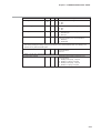
■ Process Data Area
Item
Event status summary
Address
R
W
Meaning of Data
400
401
❍
X
Reads the summary of the event occurrence status
of channels 1 to 24.
Bitmap data No.5 (see page 5-28)
-32768 to +32767
Bitmap data No.6 (see page 5-28)
0 to 256
• Even if one of the upper and lower limit events of events No.1 to No.4 occurs, the assigned bit becomes “1”.
PV value (channel 1)
411
❍
X
PV value (channel 2)
412
❍
X
PV value (channel 3)
413
❍
X
PV value (channel 4)
414
❍
X
PV value (channel 5)
415
❍
X
PV value (channel 6)
416
❍
X
PV value (channel 7)
417
❍
X
PV value (channel 8)
418
❍
X
PV value (channel 9)
419
❍
X
PV value (channel 10)
420
❍
X
PV value (channel 11)
421
❍
X
PV value (channel 12)
422
❍
X
PV value (channel 13)
423
❍
X
PV value (channel 14)
424
❍
X
PV value (channel 15)
425
❍
X
PV value (channel 16)
426
❍
X
PV value (channel 17)
427
❍
X
PV value (channel 18)
428
❍
X
PV value (channel 19)
429
❍
X
PV value (channel 20)
430
❍
X
PV value (channel 21)
431
❍
X
PV value (channel 22)
432
❍
X
PV value (channel 23)
433
❍
X
PV value (channel 24)
434
❍
X
Reads the PV values of channels 1 to 24.
-32767: Recording mode OFF
-32768: Relative humidity calculation error
-20000: Minus-side overload or overflow
-19999 to +29999: Normal input
30000: Plus-side overload or overflow
32767: Non-measured data
• The PV value after calculation is read when the calculation has been set.
• In the case of the ON/OFF range, 0 = OFF and 1 = ON.
• For details on the decimal point in linear scale ranging, refer to the engineering range decimal point (page 521).
Note
5-6
: The content of the event status summary in the process data area
(address 400W) is same as the event status summary in the event data
(address 450W). And the content of the event status summary in the
process data area (address 401W) is same as the event status summary
in the event data (address 451W).
Chapter 5. COMMUNICATION DATA TABLE
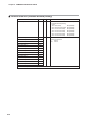
■ Event Data
Item
Event status summary
Address
R
W
Meaning of Data
450
451
❍
X
Reads the summary of the event occurrence status
of channels 1 to 24.
Bitmap data No.5 (see page 5-28)
-32768 to +32767
Bitmap data No.6 (see page 5-28)
0 to 256
• Even if one of the upper and lower limit events of events No.1 to No.4 occurs, the assigned bit becomes “1”.
Event status (channel 1)
461
❍
X
Event status (channel 2)
462
❍
X
Event status (channel 3)
463
❍
X
Event status (channel 4)
464
❍
X
Event status (channel 5)
465
❍
X
Event status (channel 6)
466
❍
X
Event status (channel 7)
467
❍
X
Event status (channel 8)
468
❍
X
Event status (channel 9)
469
❍
X
Event status (channel 10)
470
❍
X
Event status (channel 11)
471
❍
X
Event status (channel 12)
472
❍
X
Event status (channel 13)
473
❍
X
Event status (channel 14)
474
❍
X
Event status (channel 15)
475
❍
X
Event status (channel 16)
476
❍
X
Event status (channel 17)
477
❍
X
Event status (channel 18)
478
❍
X
Event status (channel 19)
479
❍
X
Event status (channel 20)
480
❍
X
Event status (channel 21)
481
❍
X
Event status (channel 22)
482
❍
X
Event status (channel 23)
483
❍
X
Event status (channel 24)
484
❍
X
Note
Reads the event occurrence status of channels 1
to 24.
Bitmap data No.7 (see page 5-29)
If the upper limit event or the lower limit event of
No.1 to No.4 of each channel occurs, the assigned
bit becomes ''1''.
: The content of the event status summary in the process data area
(address 400W) is same as the event status summary in the event data
(address 450W). And the content of the event status summary in the
process data area (address 401W) is same as the event status summary
in the event data (address 451W).
5-7
Chapter 5. COMMUNICATION DATA TABLE
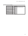
■ Digital I/O Area (data area)
Item
External switch input status
summary
5-8
Address
R
W
Meaning of Data
500
«
X
Reads the summary of No.1 to No.12 external
switch input status.
Bitmap data No.8 (see page 5-29)
0 to 4095
Reads the status of No.1 to No.12 external switch
input status.
0: OFF
1: ON
No.1 external switch input
501
«
X
No.2 external switch input
502
«
X
No.3 external switch input
503
«
X
No.4 external switch input
504
«
X
No.5 external switch input
505
«
X
No.6 external switch input
506
«
X
No.7 external switch input
507
«
X
No.8 external switch input
508
«
X
No.9 external switch input
509
«
X
No.10 external switch input
510
«
X
No.11 external switch input
511
«
X
No.12 external switch input
512
«
X
Internal contact input status
summary
520
«
X
Reads the summary of No.1 to No.12 internal
switch input status.
Bitmap data No.8 (see page 5-29)
0 to 4095
No.1 internal contact input
521
«
X
No.2 internal contact input
522
«
X
No.3 internal contact input
523
«
X
Reads the No.1 to No.12 internal contact input
status.
0: OFF
1: ON
No.4 internal contact input
524
«
X
No.5 internal contact input
525
«
X
No.6 internal contact input
526
«
X
No.7 internal contact input
527
«
X
No.8 internal contact input
528
«
X
No.9 internal contact input
529
«
X
No.10 internal contact input
530
«
X
No.11 internal contact input
531
«
X
No.12 internal contact input
532
«
X
Chapter 5. COMMUNICATION DATA TABLE
Item
Address
R
W
Meaning of Data
Relay output status summary
540
«
X
Reads the summary of the No.1 to No.12 relay
output status.
Bitmap data No.8 (see page 5-29)
0 to 4095
No.1 relay output
541
«
X
No.2 relay output
542
«
X
No.3 relay output
543
«
X
Reads the No.1 to No.12 relay output status.
0: OFF
1: ON
No.4 relay output
544
«
X
No.5 relay output
545
«
X
No.6 relay output
546
«
X
No.7 relay output
547
«
X
No.8 relay output
548
«
X
No.9 relay output
549
«
X
No.10 relay output
550
«
X
No.11 relay output
551
«
X
No.12 relay output
552
«
X
Open collector output status
summary
560
«
X
Reads the summary of the No.1 to No.12 open
collector output status.
Bitmap data No.8 (see page 5-29)
0 to 4095
No.1 open collector output
561
«
X
No.2 open collector output
562
«
X
No.3 open collector output
563
«
X
Reads the No.1 to No.12 open collector output
status.
0: OFF
1: ON
No.4 open collector output
564
«
X
No.5 open collector output
565
«
X
No.6 open collector output
566
«
X
No.7 open collector output
567
«
X
No.8 open collector output
568
«
X
No.9 open collector output
569
«
X
No.10 open collector output
570
«
X
No.11 open collector output
571
«
X
No.12 open collector output
572
«
X
5-9
Chapter 5. COMMUNICATION DATA TABLE
■ Common Data Area (common setup items)
Item
Address
R
W
Meaning of Data
No.1 chart feed speed
600
«
«
Sets and reads the No.1 chart feed speed.
1 to 480 (mm/h)
No.2 chart feed speed
601
«
«
Sets and reads the No.2 chart feed speed.
1 to 480 (mm/h)
Fixed date interval timer
602
«
«
Sets and reads the fixed date interval timer.
1: 10min
2: 20min
3: 30min
4: 1h
5: 2h
6: 3h
7: 6h
8: 12h
9: 24h
Fixed time interval timer (h)
603
«
«
Fixed time interval timer (min)
604
«
«
Sets and reads the fixed time interval timer.
H: 0 to 23
Min: 0 to 59
The possible setting range is 00:05 to 23:59.
If an attempt is made to set less than 5min, a numerical value range error (response code 44) is returned.
Sets and reads the clock date and time.
Clock: Year
605
«
«
Clock: Month
606
«
«
Month: 1 to 12
Clock: Day
607
«
«
Day:
«
H:
0 to 23
«
Min:
0 to 59
Year:
Clock: H
Clock: Min
608
609
«
«
0 to 99
1 to 31
• Non-existent dates (e.g. February 30th) cannot be set.
• If an attempt is made to set a non-existent date, a numerical value range error (response code 44) is
returned.
• If “0” to “89” is written, the year becomes 2000 onwards, and if “90” to “98” is written, the year becomes 1990
onwards.
5-10
Configuration lock
610
«
«
Reads the setting inhibited (lock), setting permitted
(unlock) and configuration lock setup on the SRF
display setup unit.
0: Unlock
1: Lock
Menu level
611
«
«
Sets and reads the menu level.
0: Level 0 displayed
1: Levels 0 and 1 displayed
2: All items displayed
Recording format
612
«
«
Sets and reads the recording format.
1: Trend
2: Trend + tabulation
3: Trend + schedule demand
4: Fixed interval tabulation
5: Fixed time tabulation
Recorder ID No.
613
«
«
Writes and reads the recorder ID No.
0 to 99
Chapter 5. COMMUNICATION DATA TABLE
Item
Address
R
W
Meaning of Data
Recording time ON/OFF
614
«
«
Sets and reads recording time ON/OFF.
0: OFF
1: ON
Scale recording ON/OFF
615
«
«
Sets and reads scale recording ON/OFF.
0: OFF
1: ON
Recording color selection
616
«
«
Selects and reads the recording color.
1: Standard type
2: DIN type
Communications access rights
617
«
X
Reads the communications access rights when the
area is accessed by CPL communications.
1: Read only
2: Read/Write
• Only during reading, writing is not possible even on write-accessible areas.
• Even during reading and writing, writing is not possible on only read-accessible areas, and reading is not
possible on only write-accessible areas.
Station address
618
«
X
Reads the communications address used in CPL
communications.
0 to 127
• When “0” is set, CPL communications is not possible.
Communications method
619
«
X
Reads the communications method for CPL
communications.
1: 4800bps, even parity, 1 stop bit
2: 4800bps, no parity, 2 stop bits
3: 9600bps, even parity, 1 stop bit
4: 9600bps, no parity, 2 stop bits
5-11
Chapter 5. COMMUNICATION DATA TABLE
■ Common Data Area (schedule demand printing)
Item
Address
R
W
Meaning of Data
Time setup ON/OFF
630
«
«
Sets and reads the No.1 to No.8 time setup used
in schedule demand printing.
0: OFF
1: No.1 time setup
ON (enabled)
2: No.1 and No.2 time setup ON (enabled)
3: No.1 to No.3 time setup
ON (enabled)
4: No.1 to No.4 time setup
ON (enabled)
5: No.1 to No.5 time setup
ON (enabled)
6: No.1 to No.6 time setup
ON (enabled)
7: No.1 to No.7 time setup
ON (enabled)
8: No.1 to No.8 time setup
ON (enabled)
No.1 time setup: h
631
«
«
No.1 time setup: min
632
No.2 time setup: h
633
Sets and reads the time when schedule demand
printing is carried out.
h:
0 to 23
min: 0 to 59
No.2 time setup: min
634
No.3 time setup: h
635
No.3 time setup: min
636
No.4 time setup: h
637
No.4 time setup: min
638
No.5 time setup: h
639
No.5 time setup: min
640
No.6 time setup: h
641
No.6 time setup: min
642
No.7 time setup: h
643
No.7 time setup: min
644
No.8 time setup: h
645
No.8 time setup: min
646
• If the time setup is not set to ON by 630W, demand printing is not carried out at the set time.
5-12
Chapter 5. COMMUNICATION DATA TABLE
■ Common Data Area (messages)
Item
Address
R
W
Meaning of Data
No.1 message
(1st character) to (12th character)
650 to 661
«
«
Character codes by which 12 characters used
for printing messages are set and read
No.2 message
(1st character) to (12th character)
662 to 673
No.3 message
(1st character) to (12th character)
674 to 685
No.4 message
(1st character) to (12th character)
686 to 697
No.5 message
(1st character) to (12th character)
698 to 709
No.6 message
(1st character) to (12th character)
710 to 721
No.7 message
(1st character) to (12th character)
722 to 733
No.8 message
(1st character) to (12th character)
734 to 745
Refer to Appendix, SRF Character Codes.
5-13
Chapter 5. COMMUNICATION DATA TABLE
■ Common Data Area (digital input)
Item
Address
R
W
Meaning of Data
No.1 external switch input
751
«
«
No.2 external switch input
752
No.3 external switch input
753
No.4 external switch input
754
No.5 external switch input
755
No.6 external switch input
756
No.7 external switch input
757
No.8 external switch input
758
No.9 external switch input
759
No.10 external switch input
760
No.11 external switch input
761
No.12 external switch input
762
Sets and reads the No.1 to No.12 external switch
inputs.
0: Function setup OFF
1: Recording ON/OFF (all channels
unconditionally)
2: Print on demand
3: Print all lists
4: Print specified lists
5: Chart feed
6: Print communications list
7: Chart feed speed/scale selection
8: Clear batch counter
11 to 16: Clear integrating calculation No.1 to No.6
21 to 28: Print No.1 to No.8 messages
31: Recording ON/OFF (channels 1 to 3)
32: Recording ON/OFF (channels 4 to 6)
33: Recording ON/OFF (channels 7 to 9)
34: Recording ON/OFF (channels 10 to 12)
35: Recording ON/OFF (channels 13 to 18)
36: Recording ON/OFF (channels 19 to 24)
40: BIN code input (bit 0)
41: BIN code input (bit 1)
42: BIN code input (bits 2)
43: BIN code input (bits 3)
44: BIN code input (bits 4)
45: BIN code input (bits 5)
• Channels in which the scale is selected by digital inputs is set by the scale switching method for each
channel.
No.1 internal contact input
771
No.2 internal contact input
772
No.3 internal contact input
773
No.4 internal contact input
774
No.5 internal contact input
775
No.6 internal contact input
776
No.7 internal contact input
777
No.8 internal contact input
778
No.9 internal contact input
779
No.10 internal contact input
780
No.11 internal contact input
781
No.12 internal contact input
782
«
«
Sets and reads the No.1 to No.12 internal switch
inputs.
0: Function setup OFF
1: Recording ON/OFF (all channels
unconditionally)
2: Print on demand
3: Print all lists
4: Print specified lists
5: Chart feed
6: Print communications list
7: Chart feed speed/scale selection
8: Clear batch counter
11 to 16: Clear integrating calculation No.1 to No.6
21 to 28: Print No.1 to No.8 messages
31: Recording ON/OFF (channels 1 to 3)
32: Recording ON/OFF (channels 4 to 6)
33: Recording ON/OFF (channels 7 to 9)
34: Recording ON/OFF (channels 10 to 12)
35: Recording ON/OFF (channels 13 to 18)
36: Recording ON/OFF (channels 19 to 24)
40: BIN code input (bit 0)
41: BIN code input (bit 1)
42: BIN code input (bits 2)
43: BIN code input (bits 3)
44: BIN code input (bits 4)
45: BIN code input (bits 5)
• Channels in which the scale is selected by digital inputs is set by the scale switching method for each
channel.
5-14
Chapter 5. COMMUNICATION DATA TABLE
■ Common Data Area (digital output)
Item
Address
R
W
Meaning of Data
No.1 relay output
801
«
«
No.2 relay output
802
No.3 relay output
803
No.4 relay output
804
No.5 relay output
805
No.6 relay output
806
No.7 relay output
807
No.8 relay output
808
No.9 relay output
809
No.10 relay output
810
Sets and reads the No.1 to No.12 relay outputs.
0: OR action/excitation/non-hold
1: OR action/excitation/hold
2: OR action/non-excitation/non-hold
3: OR action/non-excitation/hold
4: AND action/excitation/non-hold
5: AND action/excitation/hold
6: AND action/non-excitation/non-hold
7: AND action/non-excitation/hold
8: OR action/excitation/non-hold/event re-output
9: OR action/non-excitation/non-hold/event reoutput
No.11 relay output
811
No.12 relay output
812
No.1 open collector output
821
«
«
No.2 open collector output
822
No.3 open collector output
823
No.4 open collector output
824
No.5 open collector output
825
No.6 open collector output
826
No.7 open collector output
827
No.8 open collector output
828
No.9 open collector output
829
No.10 open collector output
830
Sets and reads the No.1 to No.12 open collector
outputs.
0: OR action/excitation/non-hold
1: OR action/excitation/hold
2: OR action/non-excitation/non-hold
3: OR action/non-excitation/hold
4: AND action/excitation/non-hold
5: AND action/excitation/hold
6: AND action/non-excitation/non-hold
7: AND action/non-excitation/hold
8: OR action/excitation/non-hold/event re-output
9: OR action/non-excitation/non-hold/event reoutput
No.11 open collector output
831
No.12 open collector output
832
5-15
Chapter 5. COMMUNICATION DATA TABLE
■ Common Data Area (user functions)
Item
Address
R
W
User function 1 key basic
registration
850
«
«
User function 1 assignment 1
851
User function 1 assignment 2
852
User function 1 assignment 3
853
User function 1 assignment 4
854
User function 1 assignment 5
855
User function 1 assignment 6
856
User function 1 assignment 7
857
User function 1 assignment 8
858
Meaning of Data
Sets and reads the basic registration of the user
function 1 key.
0: OFF
1: Output to internal contact input No.1
2: Call up setup items
Sets and reads the user function 1 key.
Value obtained by adding the following cardinal
numbers to the screen No. of the setup to be
registered as “0”.
Setup 0: No assignment
Setup Item
Cardinal Number
Event • • • • • • • • • • • • • • • • • • • • 1nn00
Chart feed speed • • • • • • • • • • • • • 1000
Date/time • • • • • • • • • • • • • • • • • • 1500
System • • • • • • • • • • • • • • • • • • • • 2000
Range • • • • • • • • • • • • • • • • • • • 2nn00
(Calculation setup is range setup + 5000)
Scale • • • • • • • • • • • • • • • • • • • • 3nn00
Copy • • • • • • • • • • • • • • • • • • • • • 6500
Schedule demand • • • • • • • • • • • • 2500
Message • • • • • • • • • • • • • • • • • • 3000
Extended • • • • • • • • • • • • • • • • • • 3500
External switch input • • • • • • • • • • 4000
Internal contact input • • • • • • • • • • 4100
Relay output • • • • • • • • • • • • • • • • 4200
Open collector output • • • • • • • • • • 4300
Segment 1 X-axis • • • • • • • • • • • • 5000
Segment 1 Y-axis • • • • • • • • • • • • 5100
Segment 2 X-axis • • • • • • • • • • • • 5200
Segment 2 Y-axis • • • • • • • • • • • • 5300
Segment 3 X-axis • • • • • • • • • • • • 5400
Segment 3 Y-axis • • • • • • • • • • • • 5500
“nn” indicates the channel No.
Values converted to decimal from hexadecimal are
used for the screen No.
User function 2 key basic
registration
860
«
«
Sets and reads the basic registration of the user
function 2 key.
0: OFF
1: Output to internal contact input No.2
2: Call up setup items
User function 2 assignment 1
861
«
«
Same as user function 1 assignment
User function 2 assignment 2
862
User function 2 assignment 3
863
User function 2 assignment 4
864
User function 2 assignment 5
865
User function 2 assignment 6
866
User function 2 assignment 7
867
User function 2 assignment 8
868
The calculation setup cardinal number is the value obtained by adding “5000” to the range setup cardinal
number.
5-16
Chapter 5. COMMUNICATION DATA TABLE
■ Common Data Area (copy)
Item
Address
R
W
Meaning of Data
Copy source channel
900
«
«
Sets and reads the copy source channel in
channel data copying.
1 to number of channels
Copy destination channel lower
limit
901
«
«
Sets and reads the copy destination channel lower
limit in channel data copying.
1 to (902W) value
• When 901W and 902W are written simultaneously by a single write command, the 902W data to be written
simultaneously is written normally, if it is greater than the 901W data to be written, even if the 901W data to
be written is greater than the 902W data before it is written.
For example, when 901W=1 and 902W=2, 901W=3/902W=4 can be written simultaneously.
Copy destination channel upper
limit
902
«
«
Sets and reads the copy destination channel upper
limit in channel data copying.
(901W) value to number of channels
Copy execution
903
«
«
Executes copying and reads the copy state.
0: Execution OFF/end copy
1: Copy all data
2: Copy range, calculation and scale data
3: Copy event data
4: Copy tag data
5: Copy engineering unit data
• When writing to EEPROM is started by copy execution, the response is returned before writing is completed.
If the command (even other than the copy execution command) for writing to EEPROM is received before
writing is completed, response code 31 is returned.
• When a read is carried out, “0” is always read.
Accordingly, read does not become an error response. However, it is meaningless.
• When addresses 900W to 903W contain erroneous data, not all data from 900W to 903W is written, and an
error is returned.
• The data (0 to 5) to be written to 903W is not written to EPPROM. However, the data to be copied is written to
EEPROM.
• When the values of the upper and lower limits of the copy destination channel are inverted, a numerical value
range error (response code 44) is returned.
■ Common Data Area (extended setup)
Item
Address
R
W
Meaning of Data
Initial printing ON/OFF
910
«
«
Switches initial printing (printing of various
parameters carried out when recording is started)
ON/OFF.
0: OFF
1: ON
Count function switching
911
«
«
Switches the type of count to be printed.
0: Batch count
1: BIN code
Date type selection
912
«
«
Selects the format of the date to be printed.
0: JP (YY, MM, DD)
1: US (MM, DD, YY)
2: EU (DD, MM, YY)
• JP (Japanese format): The date is printed out as “1997/09/29”
• US (American format): The date is printed out as “SEP,29,'97”.
• EU (European format): The date is printed out as “29,09,1997”.
Atmosphere
913
«
«
Sets and reads the atmospheric pressure of the
parameters used for calculating the relative
humidity.
670 to 1330 (hPa)
Thermal resistance
914
«
«
Sets and reads the resistance of the parameters
used for calculating the F value.
10 to 200
Reference contact compensation
915
«
«
Sets reference contact compensation inside the
instrument.
0: Internally OFF
1: Internally ON
5-17
Chapter 5. COMMUNICATION DATA TABLE
■ Segment Table Area
Item
Address
R
W
Segment table 1 X-axis point 01
1000
«
«
Segment table 1 X-axis point 02
1001
Segment table 1 X-axis point 03
1002
Segment table 1 X-axis point 04
1003
Segment table 1 X-axis point 05
1004
Segment table 1 X-axis point 06
1005
Segment table 1 X-axis point 07
1006
Segment table 1 X-axis point 08
1007
Segment table 1 X-axis point 09
1008
Segment table 1 X-axis point 10
1009
Segment table 1 X-axis point 11
1010
Segment table 1 X-axis point 12
1011
Segment table 1 X-axis point 13
1012
Segment table 1 X-axis point 14
1013
Segment table 1 X-axis point 15
1014
Meaning of Data
Sets and reads the break points in the segment
table.
-1000 to +11000
-1000 means -10.00%, and 11000 means 110.00%.
• Writing is possible even if the segment table is not used (nn19W=0).
Segment table 1 Y-axis point 01
1015
Segment table 1 Y-axis point 02
1016
Segment table 1 Y-axis point 03
1017
Segment table 1 Y-axis point 04
1018
Segment table 1 Y-axis point 05
1019
Segment table 1 Y-axis point 06
1020
Segment table 1 Y-axis point 07
1021
Segment table 1 Y-axis point 08
1022
Segment table 1 Y-axis point 09
1023
Segment table 1 Y-axis point 10
1024
Segment table 1 Y-axis point 11
1025
Segment table 1 Y-axis point 12
1026
Segment table 1 Y-axis point 13
1027
Segment table 1 Y-axis point 14
1028
Segment table 1 Y-axis point 15
1029
«
«
Sets and reads the break points in the segment
table.
-1000 to +11000
-1000 means -10.00%, and 11000 means 110.00%.
• Writing is possible even if the segment table is not used (nn19W=0).
5-18
Chapter 5. COMMUNICATION DATA TABLE
Item
Address
R
W
Segment table 2 X-axis point 01
1030
«
«
Segment table 2 X-axis point 02
1031
Segment table 2 X-axis point 03
1032
Segment table 2 X-axis point 04
1033
Segment table 2 X-axis point 05
1034
Segment table 2 X-axis point 06
1035
Segment table 2 X-axis point 07
1036
Segment table 2 X-axis point 08
1037
Segment table 2 X-axis point 09
1038
Segment table 2 X-axis point 10
1039
Segment table 2 X-axis point 11
1040
Segment table 2 X-axis point 12
1041
Segment table 2 X-axis point 13
1042
Segment table 2 X-axis point 14
1043
Meaning of Data
Sets and reads the break points in the segment
table.
-1000 to +11000
-1000 means -10.00%, and 11000 means 110.00%.
Segment table 2 X-axis point 15
1044
• Writing is possible even if the segment table is not used (nn19W=0).
Segment table 2 Y-axis point 01
1045
Segment table 2 Y-axis point 02
1046
Segment table 2 Y-axis point 03
1047
Segment table 2 Y-axis point 04
1048
Segment table 2 Y-axis point 05
1049
Segment table 2 Y-axis point 06
1050
Segment table 2 Y-axis point 07
1051
Segment table 2 Y-axis point 08
1052
Segment table 2 Y-axis point 09
1053
Segment table 2 Y-axis point 10
1054
Segment table 2 Y-axis point 11
1055
Segment table 2 Y-axis point 12
1056
Segment table 2 Y-axis point 13
1057
Segment table 2 Y-axis point 14
1058
Segment table 2 Y-axis point 15
1059
«
«
Sets and reads the break points in the segment
table.
-1000 to +11000
-1000 means -10.00%, and 11000 means 110.00%.
• Writing is possible even if the segment table is not used (nn19W=0).
5-19
Chapter 5. COMMUNICATION DATA TABLE
Item
Address
R
W
Segment table 3 X-axis point 01
1060
«
«
Segment table 3 X-axis point 02
1061
Segment table 3 X-axis point 03
1062
Segment table 3 X-axis point 04
1063
Segment table 3 X-axis point 05
1064
Segment table 3 X-axis point 06
1065
Segment table 3 X-axis point 07
1066
Segment table 3 X-axis point 08
1067
Segment table 3 X-axis point 09
1068
Segment table 3 X-axis point 10
1069
Segment table 3 X-axis point 11
1070
Segment table 3 X-axis point 12
1071
Segment table 3 X-axis point 13
1072
Segment table 3 X-axis point 14
1073
Meaning of Data
Sets and reads the break points in the segment
table.
-1000 to +11000
-1000 means -10.00%, and 11000 means 110.00%.
Segment table 3 X-axis point 15
1074
• Writing is possible even if the segment table is not used (nn19W=0).
Segment table 3 Y-axis point 01
1075
Segment table 3 Y-axis point 02
1076
Segment table 3 Y-axis point 03
1077
Segment table 3 Y-axis point 04
1078
Segment table 3 Y-axis point 05
1079
Segment table 3 Y-axis point 06
1080
Segment table 3 Y-axis point 07
1081
Segment table 3 Y-axis point 08
1082
Segment table 3 Y-axis point 09
1083
Segment table 3 Y-axis point 10
1084
Segment table 3 Y-axis point 11
1085
Segment table 3 Y-axis point 12
1086
Segment table 3 Y-axis point 13
1087
Segment table 3 Y-axis point 14
1088
Segment table 3 Y-axis point 15
1089
«
«
Sets and reads the break points in the segment
table.
-1000 to +11000
-1000 means -10.00%, and 11000 means 110.00%.
• Writing is possible even if the segment table is not used (nn19W=0).
5-20
Chapter 5. COMMUNICATION DATA TABLE
■ Channel Data (range)
Address “nn” is a value obtained by adding “10” to channels “1” to “24”.
For example, “nn” becomes “11” in the case of channel 1.
Item
Address
R
W
Meaning of Data
Recording mode
nn00
❍
❍
Sets and reads the recording mode.
0: OFF
1: Display
2: Display + recording
3: Digital input-dependent
Range code
nn01
❍
❍
Sets and reads the range codes to be used.
See Range Code Table (page 5-30).
• If the range code is written, the following are initialized to their defaults: measurement range decimal
point/lower limit/upper limit, engineering range decimal point/lower limit/upper limit, PV bias value, No.1 and
No.2 scale lower limit/upper limit, scale switching method, auto-switching point and auto-switching differential.
• When the range code is set to the communications input B or ON/OFF, a sub-code number is required.
Sub-code No.
nn02
❍
❍
If set for ON/OFF input range;
Sets and reads the sub-code No.
See table for “Digital data acquisition point
address” (page 5-31).
If set for communications input B;
Sets and reads the sub-code No.
See table for “PV data acquisition point
address“ (page 5-31).
• Settings are enabled only in the case of the communications input B or ON/OFF input range.
Burnout
nn03
❍
❍
Sets and reads operation at burnout.
0: OFF
1: UP
2: DOWN
Measurement range decimal point
nn04
❍
X
Reads the measurement range decimal point.
0: No digits past the decimal point
XXXXX
1: 1 digit past the decimal point
XXXX.X
2: 2 digits past the decimal point
XXX.XX
3: 3 digits past the decimal point
XX.XXX
4: 4 digits past the decimal point
X.XXXX
Measurement range lower limit
nn05
❍
❍
Sets and reads the measurement range lower limit.
-19999 to +29999
• Set the measurement range lower limit so that it is smaller than the measurement range upper limit.
• When the range code is changed, settings are initialized to their defaults.
• For details on the decimal point, refer to the measurement range decimal point (address: nn04W).
Measurement range upper limit
nn06
❍
❍
Sets and reads the measurement range upper limit.
-19999 to +29999
• Set the measurement range lower limit so that it is smaller than the measurement range upper limit.
• When the measurement range lower limit is set so that it is equal to or greater than the measurement range
upper limit, a numerical value range error (response code 44) is returned.
• When the range code is changed, settings are initialized to their defaults.
• For details on the decimal point, refer to the measurement range decimal point (address: nn04W).
5-21
Chapter 5. COMMUNICATION DATA TABLE
Item
Engineering range decimal point
Address
R
W
nn07
«
«
Meaning of Data
Sets and reads the engineering range decimal
point.
0: No digits past the decimal point
XXXXX
1: 1 digit past the decimal point
XXXX.X
2: 2 digits past the decimal point
XXX.XX
3: 3 digits past the decimal point
XX.XXX
4: 4 digits past the decimal point
X.XXXX
• If the scaling is not linear the range code setting is disabled.
• When the range code is changed, settings are initialized to their defaults.
Engineering range lower limit
nn08
«
«
Sets and reads the engineering range lower limit.
-19999 to +29999
• For details on the decimal point, refer to the engineering range decimal point (address: nn07W).
• When the range code is changed, settings are initialized to their defaults.
Engineering range upper limit
nn09
«
«
Sets and reads the engineering range upper limit.
-19999 to +29999
• For details on the decimal point, refer to the engineering range decimal point (address: nn07W).
• When the range code is changed, settings are initialized to their defaults.
PV filter
nn10
«
«
Sets and reads the PV filter.
0 to 15
• Settings are disabled in the case of the communications input range and ON/OFF input range.
PV bias
nn11
«
«
Sets and reads the PV bias.
-19999 to +29999
• Settings are disabled in the case of the communications input range and ON/OFF input range.
• When the range code is changed, settings are initialized to their defaults.
5-22
Chapter 5. COMMUNICATION DATA TABLE
■ Channel Data (calculation)
Address “nn” is a value obtained by adding “10” to channels “1” to “24”.
For example, “nn” becomes “11” in the case of channel 1.
Item
Input calculation type
Address
R
W
nn15
❍
❍
Meaning of Data
Sets and reads the input calculation type.
0: OFF (PV value)
1: Channel A - channel B
2: Fixed value - current channel
3: Current channel - fixed value
4: Integrating calculation
5: F value calculation
6: Relative humidity calculation
• When the input calculation type is changed, calculation parameters 1 to 3 are initialized to their defaults.
Calculation parameter 1
nn16
❍
❍
Sets and reads calculation parameter 1.
• When input calculation type is set to “1”:
1 to number of channels: Ach of inter-channel
deviation
• When input calculation type is set to “2”:
-19999 to +29999:fixed value of fixed value
deviation
• When input calculation type is set to “3”:
-19999 to +29999:fixed value of fixed value
deviation
• When input calculation type is set to “4”:
0: Integrating unit set to “s”
1: Integrating unit set to “min”
2: Integrating unit set to “h”
• When input calculation type is set to “5”:
0 to 2000: Value 10 times the standard
reference temperature of F value
calculation
(Example: “121.1°C” becomes “1211”.)
• When input calculation type is set to “6”:
1 to number of channels: dry-bulb temperature
input channel
• This setting is disabled when the input calculation type is set to OFF.
In this case, the numerical value range is in error if a value other than “0” is written.
• When the input calculation type is changed, the settings are initialized to their defaults.
Calculation parameter 2
nn17
❍
❍
Sets and reads the calculation parameter 2.
• When input calculation type is set to “1”:
1 to number of channels: Bch of inter-channel
deviation
• When input calculation type is set to “4”:
1 to 6: reset number of integrating calculation
• When input calculation type is set to “5”:
1 to 6: reset number of F value calculation
• When input calculation type is set to “6”:
0: Large wind speed (2.5m/s or more)
1: Medium wind speed (0.5 to 2.5m/s)
2: Small wind speed (0.5m/s or less)
• This setting is disabled when the input calculation type is set to OFF or fixed value deviation.
In this case, the numerical value range is in error if a value other than “0” is written.
• When the input calculation type is changed, the settings are initialized to their defaults.
Calculation parameter 3
nn18
❍
❍
Sets and reads integrating parameter 3.
0 to 10: Integration weighting
• This setting is disabled when the input calculation type is set to other than integrating type.
In this case, “0” to “10” can be written.
• When the input calculation type is changed, the settings are initialized to their defaults.
Segment table use
nn19
❍
❍
Sets and reads segment table use.
0: Use disabled
1: Use segment table 1
2: Use segment table 2
3: Use segment table 3
5-23
Chapter 5. COMMUNICATION DATA TABLE
■ Channel Data (scale)
Address “nn” is a value obtained by adding “10” to channels “1” to “24”.
For example, “nn” becomes “11” in the case of channel 1.
Item
No.1 scale lower limit
Address
R
W
nn20
❍
❍
Meaning of Data
Sets and reads the No.1 scale lower limit value.
-19999 to +29999
• When the range code is changed, settings are initialized to their defaults.
• For details on the decimal point, refer to the engineering range decimal point (address: nn07W).
No.1 scale upper limit
nn21
❍
❍
Sets and reads the No.1 scale upper limit value.
-19999 to +29999
• When the range code is changed, settings are initialized to their defaults.
• For details on the decimal point, refer to the engineering range decimal point (address: nn07W).
Scale switching method
nn22
❍
❍
Sets and reads the scale switching method
0: OFF
1: Automatic
2: External switch input, internal contact input or
CPL communications
• When the range code is changed, settings are initialized to their defaults.
No.2 scale lower limit
nn23
❍
❍
Sets and reads the No.2 scale lower limit value.
-19999 to +29999
• When the range code is changed, settings are initialized to their defaults.
• For details on the decimal point, refer to the engineering range decimal point (address: nn07W).
No.2 scale upper limit
nn24
❍
❍
Sets and reads the No.2 scale upper limit value.
-19999 to +29999
• When the range code is changed, settings are initialized to their defaults.
• For details on the decimal point, refer to the engineering range decimal point (address: nn07W).
Auto-switching point
nn25
❍
❍
Sets and reads the auto-switching point.
-19999 to +29999
• When the range code is changed, settings are initialized to their defaults.
Settings are not initialized even if the scale switching method is changed.
• For details on the decimal point, refer to the engineering range decimal point (address: nn07W)
Auto-switching differential
nn26
❍
❍
Sets and reads the auto-switching differential.
0 to 29999
• When the range code is changed, settings are initialized to their defaults.
Settings are not initialized even if the scale switching method is changed.
• For details on the decimal point, refer to the engineering range decimal point (address: nn07W)
Scale selection status
5-24
nn27
❍
❍
Reads the scale selection status.
1: No.1 scale
2: No.2 scale
Chapter 5. COMMUNICATION DATA TABLE
■ Channel Data (event)
●
●
Address “nn” is a value obtained by adding “10” to channels “1” to “24”.
For example, “nn” becomes “11” in the case of channel 1.
For details on the decimal point, refer to the engineering range decimal point
(address: nn07W).
Item
Address
R
W
Meaning of Data
No.1 event setting value
nn40
❍
❍
No.2 event setting value
nn41
No.3 event setting value
nn42
Sets and reads the No.1 to No.4 event setting
values.
-19999 to +29999
No.4 event setting value
nn43
No.1 event type selection
nn44
❍
❍
No.2 event type selection
nn45
No.3 event type selection
nn46
No.4 event type selection
nn47
Sets and reads the No.1 to No.4 event type
selection.
0: OFF
1: LOW
2: HIGH
No.1 event differential
nn48
❍
❍
No.2 event differential
nn49
No.3 event differential
nn50
Sets and reads the No.1 to No.4 event differential
value.
0 to 29999
No.4 event differential
nn51
No.1 event recording ON/OFF
nn52
❍
❍
No.2 event recording ON/OFF
nn53
No.3 event recording ON/OFF
nn54
Sets and reads the No.1 to No.4 event recording
ON/OFF.
0: OFF
1: ON
No.4 event recording ON/OFF
nn55
No.1 event output destination
nn56
❍
❍
No.2 event output destination
nn57
No.3 event output destination
nn58
Sets and reads the No.1 to No.4 event output
destination.
0:
OFF
1 to 12: No.1 to No.12 relay output
13 to 24: No.1 to No.12 open collector output
25 to 36: No.1 to No.12 internal contact input
No.4 event output destination
nn59
Tag (1st character) to (12th
character)
nn60
to
nn71
❍
❍
Writes and reads the tag character string (12
characters).
Refer to Appendix, SRF Character Codes.
Engineering unit (1st character) to
(6th character)
nn80
to
nn85
❍
❍
Writes and reads the engineering unit string (6
characters).
Refer to Appendix, SRF Character Codes.
5-25
Chapter 5. COMMUNICATION DATA TABLE
■ Communication Data Area
Item
Communications PV value
(communications input A *1 or
communications input B *2 )
Address
R
W
3500
to
3523
«
«
Meaning of Data
Writes and reads the communications PV value.
-19999 to +29999
• The communications PV value becomes “not fixed” when the power is turned ON again.
Communication list 1st line
(1st character) to (85th character)
3600 to
3684
«
«
Communication list 2nd line
(1st character) to (85th character)
3700 to
3784
«
«
Communication list 3rd line
(1st character) to (85th character)
3800 to
3884
«
«
Writes and reads the printed characters on the 1st
and 3rd lines of the communications list.
Refer to Appendix, SRF Character Codes.
• The 1st to the 3rd line are printed together.
• If a complete line is not all characters (20H, 84H to 8FH, A0H), that line is not printed, and the next line is
printed pushed up.
*1 Communications input A
Range code
80
81
82
83
84
85
86
87
PV data acquisition
point address
(CPL address)
3500W
3501W
3502W
3503W
3504W
3505W
3506W
3507W
*2 Communications input B
Range code Sub-code
No.
88
0
1
2
3
4
5
6
7
8
9
10
11
PV data acquisition
point address
(CPL address)
3500W
3501W
3502W
3503W
3504W
3505W
3506W
3507W
3508W
3509W
3510W
3511W
See "■ Range code tables" (Page 5-30) for details.
5-26
Range code Sub-code
No.
88
12
13
14
15
16
17
18
19
20
21
22
23
PV data acquisition
point address
(CPL address)
3512W
3513W
3514W
3515W
3516W
3517W
3518W
3519W
3520W
3521W
3522W
3523W
Chapter 5. COMMUNICATION DATA TABLE
■ Bitmap Data
No.1
Clear integrating calculation (address: 306W)
b5 b4 b3 b2 b1 b0
16 15 14 13 12 11 10
9
8
7
6
5
4
3
2
1
1 : Clear integrating calculation No.1
2 : Clear integrating calculation No.2
3 : Clear integrating calculation No.3
4 : Clear integrating calculation No.4
5 : Clear integrating calculation No.5
6 : Clear integrating calculation No.6
7 to 16 :
—
No.2
Integrating calculation status (address: 316W)
b13 b12 b11 b10 b9 b8
16 15 14 13 12 11 10
9
b5 b4 b3 b2 b1 b0
8
7
6
5
4
3
2
1
1 : 0 to 5 : Clear integration by communications No.1
2 : 0 to 5 : Clear integration by communications No.2
3 : 0 to 5 : Clear integration by communications No.3
4 : 0 to 5 : Clear integration by communications No.4
5 : 0 to 5 : Clear integration by communications No.5
6 : 0 to 5 : Clear integration by communications No.6
7, 8:
—
9 : Clear integration by DI and communications No.1
10 : Clear integration by DI and communications No.2
11 : Clear integration by DI and communications No.3
12 : Clear integration by DI and communications No.4
13 : Clear integration by DI and communications No.5
14 : Clear integration by DI and communications No.6
15, 16:
—
No.3
Instrument alarm information (address: 380W)
b15 b14 b13 b12 b11 b10 b9 b8
16 15 14 13 12 11 10
1
2
3
4
5
6
7
8
9
10
11
12
13
14
15
16
9
b6 b5 b4 b3 b2
8
7
6
5
4
3
b0
2
1
: ROM diagnosis
:
—
: EEPROM diagnosis
: Calibration data diagnosis
: Configuration data diagnosis
: Auto-zero input diagnosis
: Reference voltage diagnosis
:
—
: Reference contact temperature diagnosis
: Model No. information diagnosis
: A/D converter diagnosis
: Printer position diagnosis
: Ribbon position diagnosis
: Mode selection pin diagnosis
: Clock backup battery diagnosis
: Processing cycle diagnosis
5-27
Chapter 5. COMMUNICATION DATA TABLE
No.4
Option information (address: 398W)
b7 b6 b5 b4 b3 b2 b1 b0
16 15 14 13 12 11 10
9
8
7
6
5
4
3
2
1
1 : RS-485 communication
2 : RS-232C communication
3 : No.1 to No.4 external switch input
4 : No.5 to No.8 external switch input
5 : No.9 to No.12 external switch input
6 : No.1 to No.6 relay output
7 : No.7 to No.12 relay output
8 : No.1 to No.12 open collector output
9 to 16 :
—
No.5
Event status summary (address: 400, 450W)
b15 b14 b13 b12 b11 b10 b9 b8
b7 b6 b5 b4 b3 b2 b1 b0
16 15 14 13 12 11 10
8
1
2
3
4
5
6
7
8
9
10
11
12
13
14
15
16
No.6
9
7
6
5
4
3
2
1
: Channel 1
: Channel 2
: Channel 3
: Channel 4
: Channel 5
: Channel 6
: Channel 7
: Channel 8
: Channel 9
: Channel 10
: Channel 11
: Channel 12
: Channel 13
: Channel 14
: Channel 15
: Channel 16
Event status summary (address: 401, 451W)
b23 b22 b21 b20 b19 b18 b17 b16
16 15 14 13 12 11 10
1 : Channel 17
2 : Channel 18
3 : Channel 19
4 : Channel 20
5 : Channel 21
6 : Channel 22
7 : Channel 23
8 : Channel 24
9 to 16 :
—
5-28
9
8
7
6
5
4
3
2
1
Chapter 5. COMMUNICATION DATA TABLE
No.7
Event status (address: 461 to 484W)
b7 b6 b5 b4 b3 b2 b1 b0
16 15 14 13 12 11 10
9
8
7
6
5
4
3
2
1
1 : No.1 lower-limit event status
2 : No.1 upper-limit event status
3 : No.2 lower-limit event status
4 : No.2 upper-limit event status
5 : No.3 lower-limit event status
6 : No.3 upper-limit event status
7 : No.4 lower-limit event status
8 : No.4 upper-limit event status
9 to 16 :
—
No.8
External switch input status summary (address: 500W)
Internal contact input status summary (address: 520W)
Relay output status summary (address: 540W)
Open collector output status summary (address: 560W)
b11 b10 b9 b8
16 15 14 13 12 11 10
1
2
3
4
5
6
7
8
9
10
11
12
13 to 16
9
b7 b6 b5 b4 b3 b2 b1 b0
8
7
6
5
4
3
2
1
External Switch Input
Status Summary
Internal Contact Input
Status Summary
Relay Output
Status Summary
Open Collector Output
Status Summary
No.1 external switch input
No.1 internal switch input
No.1 relay output
No.1 open collector output
No.2 external switch input
No.2 internal switch input
No.2 relay output
No.2 open collector output
No.3 external switch input
No.3 internal switch input
No.3 relay output
No.3 open collector output
No.4 external switch input
No.4 internal switch input
No.4 relay output
No.4 open collector output
No.5 external switch input
No.5 internal switch input
No.5 relay output
No.5 open collector output
No.6 external switch input
No.6 internal switch input
No.6 relay output
No.6 open collector output
No.7 external switch input
No.7 internal switch input
No.7 relay output
No.7 open collector output
No.8 external switch input
No.8 internal switch input
No.8 relay output
No.8 open collector output
No.9 external switch input
No.9 internal switch input
No.9 relay output
No.9 open collector output
No.10 external switch input
No.10 internal switch input
No.10 relay output
No.10 open collector output
No.11 external switch input
No.11 internal switch input
No.11 relay output
No.11 open collector output
No.12 external switch input
No.12 internal switch input
No.12 relay output
No.12 open collector output
—
5-29
Chapter 5. COMMUNICATION DATA TABLE
■ Range Code Tables
Input Type
Range Code
Measurement Range
DC voltage
00
-20.00 to +20.00
Linear scaling range
01
-40.00 to +40.00
02
-60.00 to +60.00
03
-200.0 to +200.0
04
-2.000 to +2.000
05
-5.000 to +5.000
mV
V
DC voltage
Input voltage direct-reading range
mV
*1
V
Thermocouple
Resistance temperature detector
06
0.000 to 10.000
10
-20.00 to +20.00
11
-40.00 to +40.00
12
-60.00 to +60.00
13
-200.0 to +200.0
14
-2.000 to +2.000
15
-5.000 to +5.000
16
0.000 to 10.000
R
20/50
0.0 to 1760.0°C
32 to 3200°F
S
21/51
0.0 to 1760.0°C
32 to 3200°F
B
22/52
0.0 to 1820.0°C
32 to 3308°F
K
23/53
-200.0 to +1370.0°C
-328 to +2498°F
E
24/54
-220.0 to +800.0°C
-328 to +1472°F
J
25/55
-200.0 to +1100.0°C
-328 to +2012°F
T
26/56
-200.0 to +400.0°C
-328 to +752°F
N
27/57
0.0 to 1300.0°C
32 to 2372°F
WRe0-26
28/58
0.0 to 2320.0°C
32 to 4208°F
WRe5-26
29/59
0.0 to 2320.0°C
32 to 4208°F
PR40-20
30/60
0.0 to 1880.0°C
32 to 3416°F
PLII
31/61
0.0 to 1290.0°C
32 to 2354°F
Ni-Ni•Mo
32/62
0.0 to 1200.0°C
32 to 2192°F
Pt100
40/70
-200.0 to +650.0°C
-328.0 to +1202.0°F
JPt100
41/71
-200.0 to +550.0°C
-328.0 to +1022.0°F
JPt50
42/72
-200.0 to +550.0°C
-328.0 to +1022.0°F
Ni508
43/73
-50.0 to +150.0°C
-58.0 to +302.0°F
80 to 87
-19999 to +29999
88
90
-19999 to +29999
Communications input A
*2
No sub-code setting required
Communications input B
ON/OFF
*2
*3
Sub-code setting required
—
*1 Voltage value can be read directly without linear scaling.
*2 The value acquired by CPL communications is handled as a PV input value, and is processed for
recording in the same way as in usual processing.
Acquisition point address of the communications input data is set as follows:
Communications input A : If the communications input is used in less than 8 channels, the PV data
acquisition point address can be designated by setting the range codes from
"80" through to "87". Sub-code setting is not required.
Range code
5-30
80
81
82
83
84
85
86
87
PV data acquisition point address
(CPL address)
3500W
3501W
3502W
3503W
3504W
3505W
3506W
3507W
Chapter 5. COMMUNICATION DATA TABLE
Communications input B : The PV data acquisition point address can be set by selecting the range code
"88" and setting the sub-code when the communications input is used in more
than 9 channels.
Range code Sub-code
No.
0
1
2
3
4
5
6
7
8
9
10
11
88
PV data acquisition
point address
(CPL address)
3500W
3501W
3502W
3503W
3504W
3505W
3506W
3507W
3508W
3509W
3510W
3511W
Range code Sub-code
No.
88
PV data acquisition
point address
(CPL address)
12
13
14
15
16
17
18
19
20
21
22
23
3512W
3513W
3514W
3515W
3516W
3517W
3518W
3519W
3520W
3521W
3522W
3523W
*3 ON/OFF type digital signal is recorded as an input. The ON/OFF input data acquisition point
address is designated by setting the range code "90" and by the following sub-code No.:
Sub-code No.
Digital data acquisition point address
0
OFF
1 to 12
Relay output No.1 to No.12
13 to 24
Open collector output No.1 to No.12
31 to 42
External switch input No.1 to No.12
51 to 62
Internal contact input No.1 to No.12
Supplement
A digital data acquisition point address
can be designated regardless of the
presence of actual digital input and
output. However, the "OFF" status is
fixed when a digital input that is not
installed is designated.
5-31
Chapter 6.
TROUBLESHOOTING
■ Check Items in Case Communication is Disabled
1. Make sure that the RS-232C and RS-485 connections are correctly wired.
2. Make sure that the communication conditions for the SRF206/212/224 match
those of the host computer.
If any one of the below settings between stations differ, communication is
disabled.
Settings that can be used on the SRF206/212/224 are underlined.
Transmission speed:
Data length:
Parity:
Stop bit:
4800, 9600bps
8bits
No parity, even parity
1 stop bit, 2 stop bits
3. Make sure that the destination address of the command frame transmitted from
the host computer matches the address of the SRF206/212/224.
The SRF206/212/224 default address is “0”. The SRF206/212/224 will not
respond even when the destination address of the command frame is set to “00”
(30H, 30H).
4. Use the upper-case for all characters other than the device ID code (“X” or “x”
on the SRF206/212/224).
6-1
Chapter 7.
SPECIFICATIONS
■ RS-232C Specifications
Name
Remarks
Transmission mode
Unbalanced
Transmission line
3-wire system
Transmission speed (bps)
1200, 2400, 4800, 9600
Transmission distance
15m max.
Communications flow
Half duplex
Synchronization
Start-stop synchronization
Data format
8 data bits, 1 stop bit, even parity
8 data bits, 2 stop bits, no parity
Error detection
Parity check, checksum
Station address
0 to 127 (Communication function is
inhibited when set to “0”.)
Network type
1-to-1
Other
Conforms to RS-232C interface
specifications.
■ RS-485 Specifications
Remarks
Name
Transmission mode
Balanced
Transmission line
5-wire system/3-wire system
Transmission speed (bps)
1200, 2400, 4800, 9600
Transmission distance
500m max.
(300m when connected with the
MA500DIM and CMC410.)
Communications flow
Half duplex
Synchronization
Start-stop synchronization
Data format
8 data bits, 1 stop bit, even parity
8 data bits, 2 stop bits, no parity
Error detection
Parity check, checksum
Station address
0 to 127 (Communication function is
inhibited when set to “0”.)
Network type
1-to-N (31 units or less, however 16
units or less for MA500 DIM or
CMC410)
Other
Conforms to RS-485 interface
specifications.
7-1
APPENDIX
■ Code Table
0
1
2
3
4
5
6
0
SPACE
0
@
P
1
!
1
A
Q
a
q
`
7
p
2
STX
"
2
B
R
b
r
3
ETX
#
3
C
S
c
s
4
$
4
D
T
d
t
5
%
5
E
U
e
u
6
&
6
F
V
f
v
7
'
7
G
W
g
w
8
(
8
H
X
h
x
9
)
9
I
Y
i
y
*
:
J
Z
j
z
B
+
;
K
[
k
{
C
,
<
L
¥
l
—
=
M
]
m
}
E
.
>
N
^
n
~
F
/
?
O
_
o
^
A
D
LF
CR
The shaded areas (
) are not used by this communication system. (The codes
depend on the station.)
App.-1
APPENDIX
■ SRF Character Code Table
Upper
Bits
Lower
Bits
2
3
4
5
6
7
8
@
(64)
A
(65)
B
(66)
C
(67)
D
(68)
E
(69)
F
(70)
G
(71)
H
(72)
I
(73)
J
(74)
K
(75)
L
(76)
M
(77)
N
(78)
O
(79)
P
(80)
Q
(81)
R
(82)
S
(83)
T
(84)
U
(85)
V
(86)
W
(87)
X
(88)
Y
(89)
Z
(90)
[
(91)
¥
(92)
]
(93)
^
(94)
_
(95)
`
(96)
a
(97)
b
(98)
c
(99)
d
(100)
e
(101)
f
(102)
g
(103)
h
(104)
i
(105)
j
(106)
k
(107)
l
(108)
m
(109)
n
(110)
o
(111)
p
(112)
q
(113)
r
(114)
s
(115)
t
(116)
u
(117)
v
(118)
w
(119)
x
(120)
y
(121)
z
(122)
Ω
(123)
3
(32)
!
(33)
“
(34)
#
(35)
$
(36)
%
(37)
&
(38)
´
(39)
(
(40)
)
(41)
*
(42)
+
(43)
,
(44)
—
(45)
.
(46)
/
(47)
0
(48)
1
(49)
2
(50)
3
(51)
4
(52)
5
(53)
6
(54)
7
(55)
8
(56)
9
(57)
:
(58)
;
(59)
<
(60)
=
(61)
>
(62)
?
(63)
0
1
2
3
4
5
6
7
8
9
A
B
C
D
E
F
App.-2
(124)
µ
(125)
(128)
°
(129)
°
(130)
•
(131)
(132)
(133)
(134)
(135)
(136)
(137)
(138)
(139)
(140)
(141)
2
(126)
(142)
2
(127)
(143)
APPENDIX
■ Connection With CMC10L
The CMC10L001A000 is available as an RS-232C/RS-485 (5-wire system) converter from Yamatake. The following diagram shows an example of wiring, using a
straight cable for a host computer in the terminal mode:
DIGITRONIK control
or
5-wire system (slave station)
Terminating
resistor
SDA
SDB
*
*
RDA
RDB
SG
FG
RD
SD
2
2
3
3
DB
TER.
MOD.
TER.
RS
CS
DR
SG
7
7
8
8
6
6
5
5
4
4
1
1
Shielded
cable
DA
MOD.
SG
3-wire system (slave station)
Shielded
cable
DA
DB
SG
ER
CD
Host computer
FG
CMC10L
Shielded
cable
DIGITRONIK control
or
5-wire system (slave station)
SDA
SDB
Terminating
resistor
*
*
RDA
RDB
SG
FG
Connect two terminating resistors of 150Ω±5%, 1/2W min. to the instrument at
each end of the transmission line. Connect only one end of the shielded wire to the
frame ground.
(*) must be wired externally.
App.-3
APPENDIX
Connect the master station SD to the slave station RD, and the master station RD
to the slave station SD.
So, set the MODE switch on the front of the CMC10L as (MODEM/TERMI
NAL) of the host computer RS-232C connector and the type of cable
(crossover/straight) used.
RS-232C
Cable type
MODE switch
TERMINAL
Straight
MODEM
TERMINAL
Crossover
TERMINAL
MODE
Straight
TERMINAL
MODE
Crossover
MODEM
● RS-232C cable
Straight:
An RS-232C cable with a D-Sub (9-pin) connector at each end where
pins with the same number are mutually connected (for example, pin 2
to pin 2, and pin 3 to pin 3).
CD
RD
SD
ER
SG
DR
RS
CS
1
2
3
4
5
6
7
8
1
2
3
4
5
6
7
8
CD
RD
SD
ER
SG
DR
RS
CS
Crossover: An RS-232C cable with a D-Sub (9-pin) connector at each end where different number pins are connected (for example, pin 2 to pin 3, and pin 3
to pin 2).
RD
SD
RS
CS
DR
ER
CD
SG
App.-4
2
3
7
8
6
4
1
5
2
3
7
8
6
4
1
5
RD
SD
RS
CS
DR
ER
CD
SG
APPENDIX
D-Sub (25-pin)↔D-Sub (9-pin) conversion cable :
An RS-232C cable for conversion between D-Sub (25-pin) and D-Sub (9-pin).
FG
SD
RD
RS
CS
DR
ER
CD
SG
1
2
3
4
5
6
20
8
7
3
2
7
8
6
4
1
5
SD
RD
RS
CS
DR
ER
CD
SG
App.-5
Revision History
Printed
Date
Manual Number
Edition
Revised pages
98-08
99-11
CP-SP-1028E 1st Edition
2nd Edition 4-3
4-4
02-08
Appendix-2
3rd Edition 1-4
2-1
2-2
2-3, 2-4
2-5
2-6
4-2
4-12
4-13
5-21
5-26
5-30, 5-31
Chapter 6
Chapter 7
App.-3
08-03
App.-4, App.-5
4th Edition 2-2
2-3, 2-4, 2-6
5-6, 5-7
App.-2
App.-4
Description
Communication frame changed from 5 35H to
A 41H.
Checksum Example changed:
7BH→76H, 85H→8AH,
“85”, (38H) and
‰ (35H)Æ“8A”, (38H) and (41H)
Character code (124) removed.
Description of CPL communications changed,
Figure changed.
Description changed, Handling Precautions deleted.
Figure of Example of connection using changed,
Layout of RS-232C connector signals changed.
Section 2-2 RS-485 Connection Overall changed.
Figure of connection example changed,
Cable model No.changed.
Description changed.
Frame of Read instruction, EXT→ETX changed.
Item of Priority deleted.
CMA50 deleted.
Address of Range code "nn00"→"nn01" changed,
Digital signal No.→Sub-code No. changed,
description of Digital signal No.chaged,
Description of communication input B added.
Address of communication PV value 3500 to
3507→3500 to 3523 changed, Description of
communication input A and communication input
B added.
Description of communication input A and
communication input B added.
Old chapter 6. COMMUNICATION PROGRAM
FOR MASTER STATION deleted,
old chapter 7. TROUBLESHOOTING.
Old chapter 8. SPECIFICATIONS.
Description of connection with CMA50→
connection with CMC10L changed.
Description of RS-232C cable changed.
Signal table (25 pins, 14 pins) deleted.
Handling Precautions added.
Note and comment added.
Upper bits row and lower bits column corrected.
Assigned signals RD and SD changed.
Specifications are subject to change without notice.
Advanced Automation Company
1-12-2 Kawana, Fujisawa
Kanagawa 251-8522 Japan
URL: http://www.azbil.com
Printed on recycled paper.
(07)
Printed in Japan.
1st Edition: Issued in Aug. 1998(M)
4th Edition: Issued in Mar. 2008(G)