Download DVK512 User Manual
Transcript
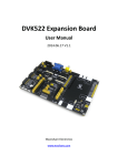
DVK512 User Manual Waveshare DVK512 User Manual Copyright All rights reserved by Waveshare Electronics Co., Ltd. Not allow to modify, distribute, or copy without permission. Revision History Revision Date Description V1.0 Aug. 18, 2014 Initial revision V1.1 Nov. 13, 2014 Figures and tables update V2.1 Nov. 27, 2014 Major update V2.2 Dec. 03, 2014 Amendment V2.3 Dec. 18, 2014 3.5inch LCD update V2.4 Jan. 01, 2015 Amend Chap. 2.13 V2.5 Mar. 06, 2015 Compatible with Raspberry Pi 2 Overview DVK512 is an expansion board designed for Raspberry Pi Model B+, integrates various components and interfaces for connecting external accessory boards. It's ideal for Raspberry Pi Model B+ evaluation and development. 1 V2.5, Mar. 6, 2015 DVK512 User Manual Waveshare 1. Pinheaders for connecting with the RPi 2. UART interface: easily connects to UART modules such as RS232, RS485, USB TO UART, etc. 3. 8I/Os interface: easily connects to modules controlled by I/Os, such as 8 Push Buttons, Logic Level Converter, Mix Board, etc. 4. SPI interface: easily connects to SPI modules such as AT45DBXX Dataflash, L3G4200D Board, etc. 5. I2C interface: easily connects to I2C modules such as PCF8574 Expansion Board, PCF8563 RTC Board, LSM303DLHC Board, etc. 6. Character LCD interface: for connecting character LCDs like LCD1602 7. USB connector: USB TO UART, supported by onboard converter CP2102 8. Power indicator 9. User LEDs 10. User Keys 11. Potentiometer: for LCD1602 contrast adjustment 12. RTC battery holder 13. PCF8563: onboard RTC chip 14. 32.768K crystal: RTC crystal 15. CP2102: onboard USB TO UART chip, for debugging 16. CP2102 jumper 17. RTC jumper 18. User LEDs jumper 19. User Keys jumper 2 V2.5, Mar. 6, 2015 DVK512 User Manual Waveshare Contents DVK512 User Manual ................................................................................................................ 1 Copyright .......................................................................................................................... 1 Revision History ................................................................................................................ 1 Overview .......................................................................................................................... 1 1. 2. Basic operations ........................................................................................................ 4 1.1 System image file programming ................................................................... 4 1.2 1.3 1.4 1.5 Serial debugging environment deploying...................................................... 4 Debugging function disable (Serial port services as common serial port......... 5 Debugging function enable.......................................................................... 6 How to work with a 3.5-inch LCD displayer ................................................... 6 1.6 1.7 3.5-inch LCD display switch to HDMI display ................................................. 8 HDMI display switch to 3.5-inch LCD display ................................................. 8 1.8 API source code .......................................................................................... 8 DVK512 and expansion function Demos ...................................................................... 9 2.1 LED Demo................................................................................................... 9 2.2 Key Demo ................................................................................................... 9 2.3 2.4 2.5 8-channel Logic Level Convertor Demo......................................................... 9 Joystick Demo ........................................................................................... 10 Buzzer and PWM....................................................................................... 11 2.6 DS18B20 Demo ......................................................................................... 11 2.7 2.8 Infrared remote control ............................................................................ 12 LCD1602 Demo ......................................................................................... 13 2.9 2.10 2.11 PCF8563 RTC Demo................................................................................... 13 PCF8591 AD Demo .................................................................................... 14 PCF8591 DA Demo .................................................................................... 15 2.12 2.13 2.14 Acceleration of Gravity and Magnetic Sensors LSM303DLHC ....................... 16 Angular rate Sensor L3G4200D .................................................................. 18 GPS Demo ................................................................................................ 18 2.15 USB WIFI Demo......................................................................................... 19 3 V2.5, Mar. 6, 2015 DVK512 User Manual Waveshare 1. Basic operations 1.1 System image file programming 1) Run the CD provided with the module. Then, find out the file with the expansion name .img under the directory of IMAGE and copy it to your PC (For the latest 2) system image file, please login the website: http://www.waveshare.net/wiki/DVK512). Format your TF card with the SDFormatter.exe. Notices: The capability of TF card in used here should be more than 4GB. In this operation, a TF card reader is also required, which has to be purchased 3) separately. Start the Win32DiskImager.exe, and select the system image file copied into your PC, then, click the button Write to program the system image file. Figure 1: Programming the system image file with Win32DiskImager.exe 1.2 Serial debugging environment deploying 1) Connect your PC to the UART TO USB interface on DVK512 via a mini USB cable; Notices: The USB part of the UART TO USB interface applied by DVK512 is a mini USB interface, while the one on Raspberry Pi board is a micro USB interface. Please take a note. 2) 3) Install the cp2102_driver; Start the software PuTTY.exe, and configure the following parameters: Serial line: it is used to select corresponding serial port. The serial port in used can be check by Device Manager. Speed: it is used to set the Baud rate: 115200. Connection type: this option should be set to Serial. 4 V2.5, Mar. 6, 2015 DVK512 User Manual Waveshare Figure 2: PuTTY settings 4) 5) And then, click the button Open. After the system is started up, you should input following information: User name: pi and Password: raspberry. Then, you can enter the serial terminal to communicate with the Raspberry Pi. Notices: In this document, the software PuTTY is always used to control the Raspberry Pi via serial port communication, unless otherwise specified. When a serial port is used for Raspberry Pi terminal debugging, it cannot service as a common serial port any more, since it is occupied by system debugging function. For more information, please refer to Section 1.3 and Section 1.4. 1.3 Debugging function disable (Serial port services as common serial port After programming the system image file described above, you may find that the serial port is set as terminal debugging output by default. In this case, you should 1) 2) input corresponding commands on the terminal to disable the debugging function of the serial port. When using a LCD displayer, you should enter following command to disable the debugging function of the serial port: root@raspberrypi:/# DIS_UART-LCD When using a HDMI displayer, you should enter following command to disable the debugging function of the serial port: root@raspberrypi:/# DIS_UART-HDMI Notices: After executing any one of the commands above, the system will 5 V2.5, Mar. 6, 2015 DVK512 User Manual Waveshare reboot automatically. After it rebooted, the terminal debugging function will be disabled and the serial port will work as a common IO. However, you will not be able to enter the terminal of the Pi via the serial port communication any more. In this case, you can use SSH or connecting an external displayer to 3) the Pi to enter LXterninal. Start a serial monitor (such as TCP232), and set the Baud rate: 115200. Then, enter the terminal and input: root@raspberrypi:/# UART_Test 4) Then, a string of character will be displayed in the serial monitor. The data transmitted by the serial monitor will be displayed in the serial monitor. Notices: Raspberry Pi can still transmit and receive data by running the serial sample application, even though its debugging function of the serial port is disabled. When the Raspberry Pi receives serial data from your PC, the received data will be returned to PC and displayed in serial software. 5) 1.4 Press the keys Ctrl+C on external keyboard to end the configuration. Debugging function enable If you need to enable the debugging function of the serial port again, please 1) following the steps described below: When using a LCD displayer, you should enter following command to enable the debugging function of the serial port: root@raspberrypi:/# EN_UART-LCD 2) When using a HDMI displayer, you should enter following command to enable the debugging function of the serial port: root@raspberrypi:/# EN_UART-HDMI 1.5 How to work with a 3.5-inch LCD displayer 1) Power off the system, and connect a 3.5-inch LCD displayer to the Pi, as Figure 3 shows. 6 V2.5, Mar. 6, 2015 DVK512 User Manual Waveshare Figure 3: Connection between a Raspberry Pi Model B+ and a 3.5-inch LCD displayer 2) 3) 4) Apply the system image described in Section 1.1, and power up the Pi. Enter the following commands for touch screen calibration: pi@raspberrypi:/$ su pi pi@raspberrypi:/$ DISPLAY=:0.0 xinput_calibrator After running these commands, there will be a prompt for four-point calibration shown in the LCD screen. Click the points one by one to finish the touch calibration. Then, the new calibration data will be displayed in the terminal, as Figure 4 shows. Please get these data for future use. Figure 4: The calibration data displayed in the terminal 5) Enter the following command to edit 99-calibration.conf: pi@raspberrypi:/$ sudo nano /etc/X11/xorg.conf.d/99-calibration.conf Figure 5: Editing 99-calibration.conf 6) Modify the data marked with red box in the Figure 5 to the new calibration data displayed in the step 4), as Figure 6 shows. 7 V2.5, Mar. 6, 2015 DVK512 User Manual Waveshare Figure 6: Modifying the data of Option “Calibration” 7) Press the keys Ctrl+X, and select the option Y to save the modification. 8) The modification will be valid after rebooting the system. Enter the following command for system rebooting: pi@raspberrypi:/$ sudo reboot Notices: In case of inaccurate touch, please perform screen calibration again and reboot the system. 1.6 3.5-inch LCD display switch to HDMI display 1) The default boot mode of the system image described in the Section 1.1 selects 3.5-inch LCD display. And there will be no output from the external HDMI displayer if you apply one under this mode. In case that you want to use HDMI display, please execute the following commands: pi@raspberrypi:/$ sudo su root@raspberrypi:/# HDMI-SYS-SHOW 2) The system will load the driver. And the Raspberry Pi will reboot automatically, when the driver download finished. After the module rebooted, waiting more than 30 seconds, there will be information display on the HDMI screen. And then, you will enter into Startx interface. 1.7 HDMI display switch to 3.5-inch LCD display 1) Enter the terminal, and input: pi@raspberrypi:/$ sudo su root@raspberrypi:/# LCD35-SYS-SHOW 2) The system will load the driver. And the Raspberry Pi will reboot automatically, when the driver download finished. After the module rebooted, waiting more than 30 seconds, there will be information display on the HDMI screen. And then, you will enter into Startx interface. 1.8 API source code The API source code referred in this document can be found under the directory: /home/pi/DVK512 (Since this directory is located in the system image file described in Section 1.1, you should enter the Raspbian to find it). 8 V2.5, Mar. 6, 2015 DVK512 User Manual Waveshare 2. DVK512 and expansion function Demos Before performing any operations described in this section, you should connect DVK512 to RPi with onboard pin headers, unless otherwise specified. 2.1 LED Demo 1) Enter the terminal, and input: root@ raspberrypi:/# LED_Test 2) 3) 2.2 2.3 The 4 LEDs will light up one by one; Press the keys Ctrl+C to end the demo. Key Demo 1) Enter the terminal, and input: root@ raspberrypi:/# KEY_Test 2) The terminal will show whether there is key-press. 8-channel Logic Level Convertor Demo 1) Connect the 8-channel Logic Level Converter to the onboard 8I/Os interface, as Figure 7 shows (Notices: The VCCA pin header on the Logic Level Converter should be connected to the 3V3 pin header of the 8I/Os connector on DVK512). Logic Level Converter DVK512 VCCB 5V GND GND B0 LED0 B1 LED2 B3 LED3 B4 KEY0 B5 KEY1 B6 KEY2 B7 DEY3 Table 1: Pin relationships between Logic Level Converter and DVK512 9 V2.5, Mar. 6, 2015 DVK512 User Manual Waveshare Figure 7: The connection between Logic Level Converter and DVK512 2) 3) 4) 2.4 Enter the terminal, and input: root@ raspberrypi:/# 8-LOGIC Press the KEY0-KEY3 on the DVK512, and the relative LED will light up. Press the keys Ctrl+C to end the demo. Joystick Demo 1) Connect the Mix Board to the 8I/Os interface; 2) Enter the terminal, and input: root@ raspberrypi:/# JOYSTICK_Test Press or move the joystick, the terminal will show the action Notices: When using the 3.5 inch LCD displayer, the LCD displayer will disturb 3) PO value read from the joystick, while the joystick program will disturb the LCD touch as well. 10 V2.5, Mar. 6, 2015 DVK512 User Manual 2.5 Buzzer and PWM 1) Connect the Mix Board to the 8I/Os interface; 2) Enter the terminal, and input: root@ raspberrypi:/# Buzzer_PWM_Test The buzzer on the Mix Board will buzz in 4 seconds. 3) 2.6 Waveshare DS18B20 Demo 1) 2) Connect the Mix Board to the 8I/Os interface; Insert the DS18B20 to the ON-WIRE interface on Mix Board, as Figure 8 shows. Figure 8: Inserting the DS18B20 to the ON-WIRE interface on Mix Board Dangerous: Please make sure the DS18B20 is connected correctly. The DS18B20 in wrong connection may generate a high temperature more than 100℃ which may cause injuries when you touch it. Figure 8 shows the correct connection between the DS18B20 and the Mix Board, in which the DS18B20 should be placed according to the shape of the icon shown on the ONE-WIRE interface of 11 V2.5, Mar. 6, 2015 DVK512 User Manual Waveshare Mix Board. 3) Enter the terminal, and input: root@ raspberrypi:/# modprobe w1-gpio root@ raspberrypi:/# modprobe w1-therm root@ raspberrypi:/# ls /sys/bus/w1/devices 2.7 4) You will see a string like 28-0000066356bc, get the last 7 numbers and letters (They are different for each DS18B20. In this example, it is 66356bc). 5) Enter the terminal, and input: root@ raspberrypi:/# DS18B20_Test 66356bc 6) The terminal will display the current temperature information. Infrared remote control 1) 2) Connect the Mix Board to the 8I/Os interface; Connect the infrared receiver to the IRM interface on Mix Board, as Figure 9 shows. Figure 9: Connecting the infrared receiver to the IRM interface on Mix Board Notices: The infrared receiver should be placed according to the shape of the icon shown on the IRM interface of Mix Board, as Figure 9 shows. 3) Enter the terminal, and input: root@ raspberrypi:/# IRM 12 V2.5, Mar. 6, 2015 DVK512 User Manual 4) Waveshare Press any key on the infrared remote controller provided by Waveshare. The terminal will display the decoded infrared signal in hexadecimal format, as Figure 10 shows. Figure 10: Terminal displays the key pressed on the infrared remote controller 5) 2.8 Press the keys Ctrl+C to end the demo. LCD1602 Demo 1) Insert the LCD1602 into the LCD1602 interface on DVK512, as Figure 11 shows. Figure 11: Inserting the LCD1602 into the LCD1602 interface on DVK512 2) Enter the terminal, and input: 3) root@ raspberrypi:/# LCD1602_Test LCD1602 will display relative information. If there is nothing shown, please adjust the potentiometer on the LCD1602. The red box in Figure 11 shows the position of the potentiometer. 2.9 PCF8563 RTC Demo 1) 2) Set the jumpers on DVK512: Connect RTC_SDA to SDA Connect RTC_SCL to SCL Install i2c-tools: If you have not installed i2c-tools yet, please enter the terminal, and input: root@ raspberrypi:/# apt-get install i2c-tools root@ raspberrypi:/# adduser pi i2c root@ raspberrypi:/# reboot 13 V2.5, Mar. 6, 2015 DVK512 User Manual Waveshare Reboot and enable i2cdetect commands. 3) Enter the terminal, and input: root@ raspberrypi:/# i2cdetect –y 1 4) Then, you will see the device address of PCF8563 connected to Raspberry Pi B+ module. Here, the device address of PCF8563 is 51, indicating that the PCF8563 is detected by Raspberry Pi. Figure 12: PCF8563 is detected by Raspberry Pi B+ module 5) Enter the terminal, and input: root@ raspberrypi:/# PCF8563 Time of PCF8563 will be shown on the terminal. 2.10 PCF8591 AD Demo 1) Connect the PCF8591 module to the I2C interface on DVK512; 2) Connect the pins AIN0 and AD0 on the PCF8591 together via a cable, as Figure 13 shows. Figure 13: connecting the pins AIN0 and AD0 together 14 V2.5, Mar. 6, 2015 DVK512 User Manual 3) Waveshare Enter the terminal, and input: root@ raspberrypi:/# PCF8591-ADC 4) The terminal will display the AD values read from ADC0-ADC3 (corresponding to the pins AIN0-AIN3 on PCF8591), as Figure 14 shows. Figure 14: Displaying the AD values read from ADC0-ADC3 2.11 PCF8591 DA Demo 1) Connect the PCF8591 module to the I2C interface on DVK512; 2) Connect the Pin AOUT on PCF8591 to the LED pin header on DVK512, as Figure 15 shows. 15 V2.5, Mar. 6, 2015 DVK512 User Manual Waveshare Figure 15: Connecting the Pin AOUT on PCF8591 to the LED pin header on DVK512 3) 4) Enter the terminal, and input: root@ raspberrypi:/# PCF8591-DAC The digital conversion value is displayed in the terminal. And the brightness of the LED indicator on DVK512 will change with the level variation on the pin AOUT. 2.12 Acceleration of Gravity and Magnetic Sensors LSM303DLHC 1) Connect the LSM303DLHC module to the I2C interface on DVK512, as Figure 16 shows. 16 V2.5, Mar. 6, 2015 DVK512 User Manual Waveshare Figure 16: Connecting the LSM303DLHC module to the I2C interface on DVK512 Notices: LSM303DLHC module has two rows of pins, and the one connected to DVK512 contains the pins SDA and SCL. Enter the terminal, and input: root@ raspberrypi:/# LSM303 The terminal will display the relative values read from acceleration of gravity and magnetic sensor, as Figure 17 shows. 2) 3) Figure 17: Relative values read from acceleration of gravity and magnetic sensor 17 V2.5, Mar. 6, 2015 DVK512 User Manual Waveshare 2.13 Angular rate Sensor L3G4200D Before performing the following operations, you should remove the 3.5-inch LCD 1) 2) displayer first. Connect the L3G4200D to the SPI interface on DVK512; Remove the 3.5-inch LCD displayer; 3) Connect a HDMI displayer to Raspberry Pi module (In here, you can also use SSH 4) to build a connection to Raspberry Pi module); Enter the terminal, and input: root@ raspberrypi:/# HDMI-SYS-SHOW (From 3.5-inch LCD display switch to HDMI display) Notices: The L3G4200D Board needs to use the SPI interface. However, if the system boots from LCD display mode, the SPI interface will be occupied by the LCD displayer. Therefore, you should remove the LCD, connect a HDMI displayer, and switch to HDMI display mode to release the SPI, before using the L3G4200D Board (For more detailed information, please refer to the Section 5) 6) 7) 1.6). The system will load the driver (wait several minutes). And the Raspberry Pi will reboot automatically, when the driver download finished. After the module rebooted, waiting more than 30 seconds, there will be information display on the HDMI screen. And then, you will enter into Startx interface; Enter the terminal, and input: root@ raspberrypi:/# L3G4200D The terminal will display the angular velocity values in three factors of x axis, y axis and z axis, respectively. Figure 18: Angular velocity values 2.14 GPS Demo 1) In the default boot mode of the system image provided by Waveshare, the serial port works as terminal debugging output. In order to control peripherals via serial port communication, you should input corresponding commands on the terminal to disable the debugging function of the serial port. When using a LCD displayer, you should enter following command to disable the debugging function of the serial port: root@raspberrypi:/# DIS_UART-LCD When using a HDMI displayer, you should enter following command to disable the debugging function of the serial port: root@raspberrypi:/# DIS_UART-HDMI 18 V2.5, Mar. 6, 2015 DVK512 User Manual Waveshare Notices: For more detailed information, please refer to the Section 1.3. 2) The system reboots automatically. After it rebooted, the terminal debugging function is disabled and the serial port works as a common IO; 3) Insert a GPS module into the UART interface on DVK512, and remove the jumper wire from UART JMP, as Figure 19 shows. Figure 19: Removing the jumper wire from UART JMP 4) 5) 6) Enter the terminal, and input the following commands to set the Baud rate (The Baud rate will be restored to the default value: 115200, after the system rebooted). root@raspberrypi:/# stty -F /dev/ttyAMA0 38400 root@raspberrypi:/# gpsd /dev/ttyAMA0 -F /var/run/gpsd.sock Enter the terminal and input the following command to open the GPS software provided by the Linux system: root@raspberrypi:/# cgps -s The terminal will display relative GPS position information. Figure 20: GPS position information 2.15 USB WIFI Demo In this operation, we only need a USB WIFI module, but the DVK512 expansion board is in no used. 1) Enter the terminal, and input: root@ raspberrypi:/# iwlist wlan0 scan (Check the WIFI signal) 19 V2.5, Mar. 6, 2015 DVK512 User Manual Waveshare root@ raspberrypi:/# nano /etc/network/interfaces (Edit the configuration info 2) of the network card) Configure the settings according to your WIFI environment condition: auto lo// Use localhost iface lo inet loopback iface eth0 inet dhcp auto wlan0// If there is a wlan device, use “wlan0” as device name allow-hotplug wlan0 // The wlan device supports plug-and-play function iface wlan0 inet dhcp// If there is a WLAN network card (wlan0) in used, use DHCP to get the IP address wpa-ssid YourSSID // Connected SSID name, that is WIFI name 3) wpa-psk YourPSK// Authentication password, that is WIFI password Press the keys Ctrl+X, and select the option Y to save the modification 4) Enter the terminal, and input: root@ raspberrypi:/# /etc/init.d/networking restart (Restart the network) root@ raspberrypi:/# ping www.waveshare.net (Test the connection statue) 20 V2.5, Mar. 6, 2015


