1
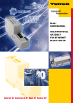
BL20 –
USER MANUAL
FOR
CANopen
E_co.fm Seite I Montag, 13. Oktober 2003 8:40 08
All brand and product names are trademarks or registered trade
marks of the owner concerned.
Edition 03/2008
© Hans Turck GmbH, Mülheim an der Ruhr
All rights reserved, including those of the translation.
No part of this manual may be reproduced in any form (printed,
photocopy, microfilm or any other process) or processed, duplicated or distributed by means of electronic systems without written
permission of Hans Turck GmbH & Co. KG, Mülheim an der Ruhr.
Subject to alterations without notice.
Safety Notes!
Before starting the installation
Disconnect the power supply of the device.
Ensure that devices cannot be accidentally restarted.
Verify isolation from the supply.
Earth and short circuit.
Cover or enclose neighboring units that are live.
Follow the engineering instructions (AWA) of the device
concerned.
Only suitably qualified personnel in accordance with EN 50 1101/-2 (VDE 0 105 Part 100) may work on this device/system.
Before installation and before touching the device ensure that
you are free of electrostatic charge.
The functional earth (FE) must be connected to the protective
earth (PE) or to the potential equalization. The system installer is
responsible for implementing this connection.
Connecting cables and signal lines should be installed so that
inductive or capacitive interference do not impair the automation
functions.
Install automation devices and related operating elements in
such a way that they are well protected against unintentional
operation.
Suitable safety hardware and software measures should be
implemented for the I/O interface so that a line or wire breakage
on the signal side does not result in undefined states in the automation devices.
Ensure a reliable electrical isolation of the low voltage for the 24
volt supply. Only use power supply units complying with IEC 60
364-4-41 (VDE 0 100 Part 410) or HD 384.4.41 S2.
Deviations of the mains voltage from the rated value must not
exceed the tolerance limits given in the specifications, otherwise
this may cause malfunction and dangerous operation.
Emergency stop devices complying with IEC/EN 60 204-1 must
be effective in all operating modes of the automation devices.
Unlatching the emergency-stop devices must not cause restart.
I
Devices that are designed for mounting in housings or control
cabinets must only be operated and controlled after they have
been installed with the housing closed. Desktop or portable units
must only be operated and controlled in enclosed housings.
Measures should be taken to ensure the proper restart of
programs interrupted after a voltage dip or failure. This should
not cause dangerous operating states even for a short time. If
necessary, emergency-stop devices should be implemented.
Wherever faults in the automation system may cause damage to
persons or property, external measures must be implemented to
ensure a safe operating state in the event of a fault or malfunction (for example, by means of separate limit switches, mechanical interlocks etc.).
The electrical installation must be carried out in accordance with
the relevant regulations (e. g. with regard to cable cross
sections, fuses, PE).
All work relating to transport, installation, commissioning and
maintenance must only be carried out by qualified personnel.
(IEC 60 364 and HD 384 and national work safety regulations).
All shrouds and doors must be kept closed during operation.
II
Table of Contents
About this Manual
Documentation Concept ............................................................................... 0-2
Overview ....................................................................................................... 0-3
Prescribed Use ........................................................................................ 0-3
Notes Concerning Planning /Installation of this Product ........................ 0-3
Description of Symbols Used.................................................................. 0-4
List of Revisions ............................................................................................ 0-5
1
BL20 Philosophy
The Basic Concept........................................................................................ 1-2
BL20 Components ........................................................................................ 1-5
Gateways................................................................................................. 1-5
Power Distribution Modules .................................................................... 1-6
Electronics Modules ................................................................................ 1-7
Base Modules.......................................................................................... 1-9
End Plate ............................................................................................... 1-11
End Bracket........................................................................................... 1-12
Jumpers................................................................................................. 1-13
Marking Material.................................................................................... 1-14
Shield Connection, 2-Pole for Analog Modules .................................... 1-15
2
Short description of CANopen
CANopen ...................................................................................................... 2-2
General .................................................................................................... 2-2
Communication ....................................................................................... 2-3
BL20 and CANopen ...................................................................................... 2-7
Electronic data sheet – EDS file .................................................................... 2-8
3
BL20 - Gateway for CANopen
Introduction ................................................................................................... 3-2
Function ........................................................................................................ 3-3
Technical Information.................................................................................... 3-4
Technical Data .............................................................................................. 3-6
General Technical Data ........................................................................... 3-6
Structure Diagram of a Gateway ........................................................... 3-11
Technical Data BL20-GW-CANOPEN ................................................... 3-11
D301087 0308 - BL20 CANopen
i
Technical Data BL20-GWBR-CANOPEN .............................................. 3-13
Connections for data cables to BL20-GW-CANOPEN ............................... 3-15
Fieldbus connection via SUB-D socket................................................. 3-15
Fieldbus connection through direct wiring ............................................ 3-16
Connections of the data cables to BL20-GWBR-CANopen ....................... 3-18
Fieldbus connection via Open Style connector..................................... 3-18
Service Interface Connection ................................................................ 3-20
Setting the bit transfer rate through DIP-switches...................................... 3-22
Node-ID Setting .......................................................................................... 3-24
Acceptance of the BL20 Station Configuration .......................................... 3-26
Status Indicators/ Diagnostic Messages Gateway ..................................... 3-27
Diagnostic Messages via LEDs ............................................................. 3-27
4
BL20 - Communication in CANopen
Setting up communication ............................................................................ 4-6
Minimum Boot-up ................................................................................... 4-6
Identifier for the Standard Objects ........................................................ 4-10
Set up Node Guarding Protocol ............................................................ 4-13
Boot-up Message.................................................................................. 4-15
Parameterization through Service Data Objects (SDO) .............................. 4-16
Read (Read from Object Dictionary)...................................................... 4-17
Write (Write to Object Dictionary) .......................................................... 4-18
Commanded Parameter Storing/Restoring........................................... 4-21
Transmission of Process Data Objects (PDO) ............................................ 4-22
Communication Parameter COB-ID...................................................... 4-22
Transmission Type ................................................................................ 4-23
Inhibit Time ............................................................................................ 4-24
Event Timer ........................................................................................... 4-24
Available PDOs...................................................................................... 4-25
Mapping Objects in PDOs..................................................................... 4-25
Default-PDOs and PDO-Mappings ....................................................... 4-26
BL20-Specific Default-PDOs................................................................. 4-28
Mappable Objects ................................................................................. 4-32
Procedure for Altering PDO-Mappings ................................................. 4-34
Object Dictionary ........................................................................................ 4-35
Overview of all Objects.......................................................................... 4-35
Commands for "Parameter Save" and "Restore Defaults" ................... 4-40
Objects for the Communication Profile ................................................. 4-42
Objects for the Transfer of Service Data ............................................... 4-72
ii
D301087 0308 - BL20 CANopen
Objects for the Transfer of Process Output Data.................................. 4-74
Objects for the Transfer of Process Input data ..................................... 4-83
Objects for Network Management ........................................................ 4-92
Manufacturer Specific Objects............................................................ 4-103
I/O-Module Objects .................................................................................. 4-110
Overview of the I/O-Module Objects................................................... 4-110
General I/O-Objects ............................................................................ 4-113
Objects for Digital Input Modules........................................................ 4-114
Objects for Digital Output Modules..................................................... 4-121
Objects for Analog Input Modules....................................................... 4-137
Objects for Analog Output Modules.................................................... 4-155
Objects for RS232/RS4xx-modules .................................................... 4-163
Objects for SSI-Modules ..................................................................... 4-176
Objects for Counter-Modules.............................................................. 4-199
Objects for SWIRE modules................................................................ 4-255
Representation of process input data ................................................. 4-257
Representation of process output data............................................... 4-261
5
Diagnostics - Emergency Frames
General.......................................................................................................... 5-2
Structure of the Emergency Frames ............................................................. 5-3
Error Register .......................................................................................... 5-4
Gateway-Diagnostics.................................................................................... 5-5
I/O-Module Diagnostics ................................................................................ 5-7
Digital Input Modules .............................................................................. 5-7
Digital Output Modules ........................................................................ 5-10
Analog Input Modules ........................................................................... 5-11
Technology Modules ............................................................................. 5-16
6
Guidelines for Station Planning
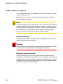
Random Module Arrangement...................................................................... 6-2
Complete Planning .................................................................................. 6-2
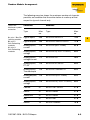
Maximum System Extension ................................................................... 6-2
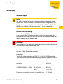
Power Supply................................................................................................ 6-5
Gateway Supply ...................................................................................... 6-5
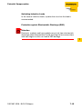
Module Bus Refreshing ........................................................................... 6-5
Creating Potential Groups ..................................................................... 6-11
Protecting the Service Interface on the Gateway.................................. 6-12
C-Rail (Cross Connection)..................................................................... 6-13
Direct Wiring of Relay Modules ............................................................. 6-15
D301087 0308 - BL20 CANopen
iii
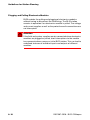
Plugging and Pulling Electronics Modules.................................................. 6-16
Extending an Existing Station ..................................................................... 6-17
Firmware Download .................................................................................... 6-18
7
Guidelines for Electrical Installation
General Notes ............................................................................................... 7-2
General .................................................................................................... 7-2
Cable Routing.......................................................................................... 7-2
Cable Routing Inside and Outside of Cabinets ....................................... 7-2
Lightning Protection ................................................................................ 7-3
Transmission Cables ............................................................................... 7-3
Cable Types ............................................................................................ 7-4
Potential Relationships ................................................................................. 7-5
General .................................................................................................... 7-5
Potential-Free Installation........................................................................ 7-6
Non-isolated Installation.......................................................................... 7-6
Electromagnetic Compatibility (EMC) ........................................................... 7-7
Ensuring Electromagnetic Compatibility ................................................. 7-7
Grounding of Inactive Metal Components .............................................. 7-7
PE Connection......................................................................................... 7-8
Earth-Free Operation............................................................................... 7-8
Mounting Rails......................................................................................... 7-9
EMC Compliant Cabinet Installation ..................................................... 7-10
Shielding of cables...................................................................................... 7-11
Potential Compensation.............................................................................. 7-13
Switching Inductive Loads .................................................................... 7-15
Protection against Electrostatic Discharge (ESD) ................................. 7-15
Bus Connection .......................................................................................... 7-16
Two-Pole Shield Connection ...................................................................... 7-17
8
BL20-Approvals for Zone 2/ Division 2
Certified BL20-Components ......................................................................... 8-2
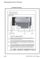
Certificates for Europe .................................................................................. 8-4
Type Examination Certificate .................................................................. 8-4
ATEX IEC Rev.1.doc.............................................................................. 8-10
Declaration of Conformity/ Konformitätserklärung................................ 8-11
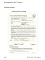
Zertifikate für Europa .................................................................................. 8-12
Baumusterprüfbescheinigung ............................................................... 8-12
iv
D301087 0308 - BL20 CANopen
ATEX IEC Rev.1.doc.............................................................................. 8-18
Declaration of Conformity/Konformitätserklärung................................. 8-19
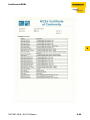
Certificates IECEx ....................................................................................... 8-20
IECEx Certificate of Conformity ............................................................ 8-20
ATEX IEC Rev.1.doc.............................................................................. 8-25
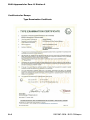
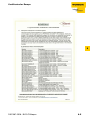
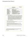
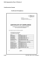
Certificates for the USA .............................................................................. 8-26
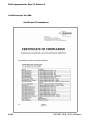
Certificate Of Compliance ..................................................................... 8-26
Installation Drawings ............................................................................. 8-30
Certificates for Canada ............................................................................... 8-32
Certificate Of Compliance ..................................................................... 8-32
Installation Drawings ............................................................................. 8-36
9
Glossary
10
Index
D301087 0308 - BL20 CANopen
v
vi
D301087 0308 - BL20 CANopen
About this Manual
Documentation Concept .................................................................... 2
Overview ............................................................................................ 3
Prescribed Use ............................................................................................3
Notes Concerning Planning /Installation of this Product ............................3
Description of Symbols Used......................................................................4
List of Revisions ................................................................................ 5
D301087 0308 - BL20 CANopen
0-1
About this Manual
Documentation Concept
This manual contains all information about the BL20-gateway for
CANopen.
The following chapters contain a short BL20 system description, a
description of the field bus system CANopen, exact information
about function and structure of the BL20 CANopen-gateway as well
as all bus-specific information concerning the connection to automation devices, the maximum system extension etc.
The bus-independent I/O-modules for BL20 as well as all further
fieldbus-independent chapters like mounting, labelling etc. are
described in a separate manual.
BL20 I/O-modules
(TURCK-Documentation-No.: English D300717)
Furthermore, the manual contains a short description of the project
planning and diagnostics software for TURCK I/O-systems, the
software I/O-ASSISTANT.
0-2
D301087 0308 - BL20 CANopen
Overview
Overview
Attention
Please read this section carefully. Safety aspects cannot be left to
chance when dealing with electrical equipment.
This manual includes all information necessary for the prescribed
use of BL20 products. It has been specially conceived for personnel
with the necessary qualifications.
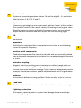
Prescribed Use
Warning
The devices described in this manual must be used only in applications prescribed in this manual or in the respective technical descriptions, and only with certified components and devices from
third party manufacturers.
Appropriate transport, storage, deployment and mounting as well as
careful operating and thorough maintenance guarantee the troublefree and safe operation of these devices.
Notes Concerning Planning /Installation of this Product
Warning
All respective safety measures and accident protection guidelines
must be considered carefully and without exception.
D301087 0308 - BL20 CANopen
0-3
About this Manual
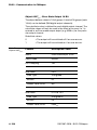
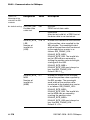
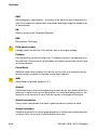
Description of Symbols Used
Warning
This sign can be found next to all notes that indicate a source of hazards. This can refer to danger to personnel or damage to the system
(hardware and software) and to the facility.
This sign means for the operator: work with extreme caution.
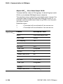
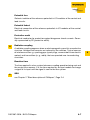
Attention
This sign can be found next to all notes that indicate a potential
hazard.
This can refer to possible danger to personnel and damages to the
system (hardware and software) and to the facility.
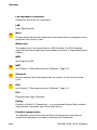
Note
This sign can be found next to all general notes that supply important information about one or more operating steps. These specific
notes are intended to make operation easier and avoid unnecessary
work due to incorrect operation.
0-4
D301087 0308 - BL20 CANopen
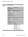
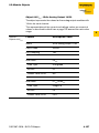
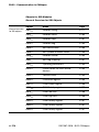
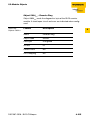
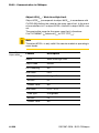
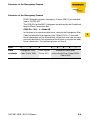
List of Revisions
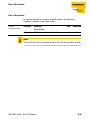
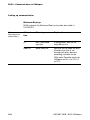
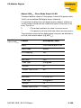
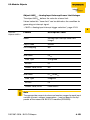
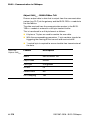
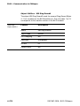
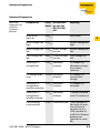
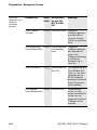
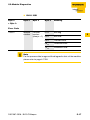
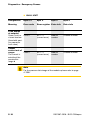
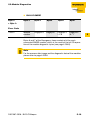
List of Revisions
In comparison to the previous manual edition, the following
changes/ revisions have been made:
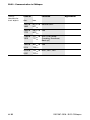
Table 1:
List of revisions
Chapter
Subject/
Description
Ch. 8
BL20-Approvals for Zone 2
new
changed
X
Note
The publication of this manual renders all previous editions invalid.
D301087 0308 - BL20 CANopen
0-5
About this Manual
0-6
D301087 0308 - BL20 CANopen
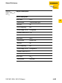
1
BL20 Philosophy
The Basic Concept ............................................................................ 2
BL20 Components ............................................................................. 5
Gateways.....................................................................................................5
– Gateways with integrated power supply .................................................5
– Gateways without power supply ............................................................6
Power Distribution Modules ........................................................................6
Electronics Modules ....................................................................................7
Base Modules..............................................................................................9
End Plate ...................................................................................................11
End Bracket...............................................................................................12
Jumpers.....................................................................................................13
Marking Material........................................................................................14
Shield Connection, 2-Pole for Analog Modules ........................................15
D301087 0308 - BL20 CANopen
1-1
BL20 Philosophy
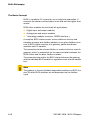
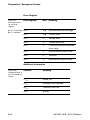
The Basic Concept
BL20 is a modular I/O system for use in industrial automation. It
connects the sensors and actuators in the field with the higher-level
master.
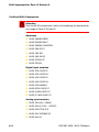
BL20 offers modules for practically all applications:
Digital input and output modules
Analog input and output modules
Technology modules (counters, RS232 interface...)
A complete BL20 station counts as one station on the bus and
therefore occupies one fieldbus address in any given fieldbus structure. A BL20 station consists of a gateway, power distribution
modules and I/O modules.
The connection to the relevant fieldbus is made via the bus-specific
gateway, which is responsible for the communication between the
BL20 station and the other fieldbus stations.
The communication within the BL20 station between the gateway
and the individual BL20 modules is regulated via an internal module
bus.
Note
The gateway is the only fieldbus-dependent module on a BL20 station. All other BL20 modules are not dependent on the fieldbus
used.
1-2
D301087 0308 - BL20 CANopen
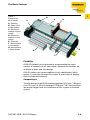
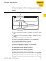
The Basic Concept
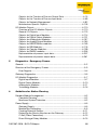
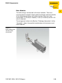
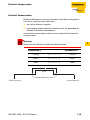
Figure 1:
Example of a
BL20 station
A Gateway
B Power distribution module
C Electronics
module in block
design
D Electronics
module in slice
design
E End plate
F Base module
in slice design
G Base module
in block design
1
B
C
A
D
E
G
F
Flexibility
All BL20 stations can be planned to accommodate the exact
number of channels to suit your needs, because the modules are
available in block and slice design.
A BL20 station can contain modules in any combination, which
means it is possible to adapt the system to practically all applications in automated industry.
Compactness
The slim design of the BL20 modules (gateway 50.4 mm / 1.98 inch,
slice 12.6 mm / 0.49 inch and block 100.8 mm / 3.97 inch) and their
low overall height favor the installation of this system in confined
spaces.
D301087 0308 - BL20 CANopen
1-3
BL20 Philosophy
Easy to handle
All BL20 modules, with the exception of the gateway, consist of a
base module and an electronics module.
The gateway and the base modules are snapped onto a mounting
rail. The electronics modules are plugged onto the appropriate base
modules.
The base modules are designed as terminal blocks. The wiring is
secured by tension clamp or screw connection. The electronics
modules can be plugged or pulled when the station is being
commissioned or for maintenance purposes, without having to
disconnect the field wiring from the base modules.
1-4
D301087 0308 - BL20 CANopen
BL20 Components
BL20 Components
1
For a detailed explanation of the individual BL20 components,
please refer to chapter 2 and chapter 4. The "Appendix" to this
manual contains (amongst others) a list of all BL20 components and
the assignment of electronics modules to base modules.
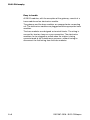
Gateways
The gateway connects the fieldbus to the I/O modules. It is responsible for handling the entire process data and generates diagnostic
information for the higher-level master and the software tool
I/Oassistant.
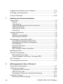
Gateways with integrated power supply
The BL20 gateway BL20-GWBR-CANOPEN offers an integrated
power supply unit for feeding the gateway and the connected I/O
modules.
It is not necessary to supply each individual module with a separate
voltage
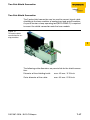
Figure 2:
Gateway
BL20-GWBRCANOPEN
D301087 0308 - BL20 CANopen
1-5
BL20 Philosophy
Gateways without power supply
Note
The gateways without integrated power supply unit need an additional power supply module (bus refreshing module) which feeds the
gateway an the connected I/O modules.
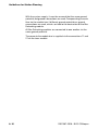
Power Distribution Modules
The power supply for gateways and I/O modules is fed to the power
distribution modules; therefore, it is not necessary to supply each
individual module with a separate voltage.
Figure 3:
Power distribution
module
1-6
D301087 0308 - BL20 CANopen
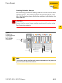
BL20 Components
Electronics Modules
1
Electronics modules contain the functions of the BL20 modules
(power distribution modules, digital and analog input/output
modules, and technology modules).
Electronics modules are plugged onto the base modules and are not
directly connected to the wiring. The assignment table in the Section
"Ordering Information" of the "Appendix" shows the possible
combinations of electronics and base modules. They can be
plugged or pulled when the station is being commissioned or for
maintenance purposes, without having to disconnect the field wiring
from the base modules.
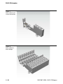
Figure 4:
Electronics
module in slice
design
D301087 0308 - BL20 CANopen
1-7
BL20 Philosophy
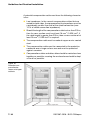
Figure 5:
Electronics
module in block
design
1-8
D301087 0308 - BL20 CANopen
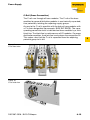
BL20 Components
Base Modules
1
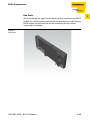
The field wiring is connected to the base modules. These are
constructed as terminals in block and slice designs and are available
in the following variations with either tension clamp or screw
connections: 2-/3-wire (2-channel), 4-wire (2-channel) and 4x 2-/3wire (4-channel).
The assignment table in the Section "Ordering Information" of the
"Appendix" shows the possible combinations of electronics and
base modules.
Figure 6:
Base module with
tension clamp
connection
D301087 0308 - BL20 CANopen
1-9
BL20 Philosophy
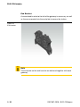
Figure 7:
Base module with
screw connection
Figure 8:
Base module in
block design
1-10
D301087 0308 - BL20 CANopen
BL20 Components
End Plate
1
An end plate on the right-hand side physically completes the BL20
station. An end bracket mounted into the end plate ensures that the
BL20 station remains secure on the mounting rail even when
subjected to vibration.
Figure 9:
End plate
D301087 0308 - BL20 CANopen
1-11
BL20 Philosophy
End Bracket
A second end bracket to the left of the gateway is necessary, as well
as the one mounted into the end plate to secure the station.
Figure 10:
End bracket
Note
The end plate an the end bracket are delivered together with each
gateway.
1-12
D301087 0308 - BL20 CANopen
BL20 Components
Jumpers
1
Jumpers (QVRs) are used to bridge a connection level of a 4-wire
base module. They can be used to connect potentials in relay
modules (bridging the relay roots); thus considerably reducing the
amount of wiring.
Figure 11:
Jumpers
D301087 0308 - BL20 CANopen
1-13
BL20 Philosophy
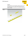
Marking Material
Labels: for labeling BL20 electronics modules.
Markers: for colored identification of connection levels of BL20
base modules.
Dekafix connector markers: for numbering the mounting slots on
BL20 base modules.
Figure 12:
Marking material
1-14
D301087 0308 - BL20 CANopen
BL20 Components
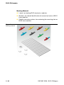
Shield Connection, 2-Pole for Analog Modules
1
The 2-pole shield connection can be used to connect signal-cable
shielding to the base modules of analog input and output modules.
A special tension-clamp operating tool (BL20-ZBW5-2) is required
to mount the shield connection onto the base module.
Figure 13:
Shield connection
D301087 0308 - BL20 CANopen
1-15
BL20 Philosophy
1-16
D301087 0308 - BL20 CANopen
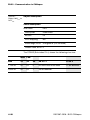
2
Short description of CANopen
CANopen ........................................................................................... 2
General ........................................................................................................2
Communication ...........................................................................................3
– Network Management Messages ............................................................3
– Service Data Objects (SDOs) ...................................................................4
– Process Data Objects (PDOs) .................................................................4
– Special Function Objects ........................................................................6
BL20 and CANopen............................................................................ 7
Electronic data sheet – EDS file ........................................................ 8
D301087 0308 - BL20 CANopen
2-1
Short description of CANopen
CANopen
Note
The following description of CANopen is an excerpt from the homepage of CiA (CAN in Automation), the international users’ and manufacturers’ organization for CAN.
General
CANopen is an open, non-proprietary network protocol. It consists
of a profile family, based on a communication profile and several
device profiles. The CANopen communication profile is standardized as CiA DS-301 (Application Layer and Communication Profile).
The CANopen device profile for I/O-modules has been published as
CiA DS-401 (Device Profile for I/O-Modules).
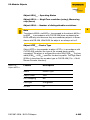
CANopen is based on the following standards:
ISO 11 898 (Physical and Data Link Layer)
Layers 1 and 2 of the ISO/OSI communication model
CiA DS-301 (Application Layer and Communication Profile)
C ANopen communication profile
CiA DS-302 (Framework for Programmable CANopen Devices)
CANopen Network Management NMT
CiA DS-401 (Device Profile for I/O-modules)
CiA DS-406 (Device Profile for Encoders)
CANopen device profile for counter modules
CiA DS-102 (CAN Physical Layer for Industrial Applications)
General application in the field sector (connectors and bit rates)
on the basis of ISO 11898
2-2
D301087 0308 - BL20 CANopen
CANopen
Communication
The lower layers of CANopen are defined according to the ISO-OSI
model in the ISO 11898 standard.
Communication between the individual nodes is made by transmitting "Telegrams".
4 different types of telegram message are defined for CANopen:
Network management messages
Service data objects SDO
Process data objects PDO
Predefined messages
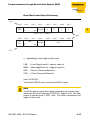
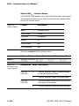
Network Management Messages
Network management messages are used in the network to control
the nodes and their operating states. This type of message makes it
possible, for instance, to configure the data transmission mechanism of a node.
The Network Management objects include Boot-up message,
Heartbeat protocol and NMT message.
Boot-up message, Heartbeat and Node Guarding are implemented
as single CAN frames with 1-byte data field.
The NMT message is mapped to a single CAN frame with a data
length of 2 byte. Its identifier is 0. The first byte contains the
command specifier and the second contains the Node-ID of the
device that must perform the command (in the case of Node-ID 0 all
nodes have to perform the command). The NMT message transmitted by the NMT master forces the nodes to transit to another
NMT state. The CANopen state machine specifies the states Initialization, Pre-Operational, Operational and Stopped. After power-on,
each CANopen device is in the state Initialization and automatically
transits to the state Pre-operational. In this state, transmission of
SDOs is allowed. If the NMT master has set one or more nodes into
the state Operational, they are allowed to transmit and to receive
PDOs. In the state Stopped no communication is allowed except
that of NMT objects.
The state Initialization is divided into three sub-states in order to
enable a complete or partial reset of a node. In the sub-state Reset
Application the parameters of the manufacturer-specific profile area
and the standardized device profile area are set to their power-on
values. In the sub-state Reset Communication the parameters of the
D301087 0308 - BL20 CANopen
2-3
2
Short description of CANopen
communication profile area are set to their power-on values. The
third sub-state is initializing, which a node enters automatically after
power-on. Power-on values are the last stored parameters.
The Heartbeat protocol is for error control purposes and signals
the presence of a node and its state. The Heartbeat message is a
periodic message of the node to one or several other nodes. It indicates that the sending node is still working properly.
A device sends the Boot-up message to indicate to the NMT
master that it has reached the state Pre-operational. This occurs
whenever the device initially boots-up but also after a power-out
during operation. The Boot-up message has the same identifier as
the Heartbeat object, however, its data content is zero.
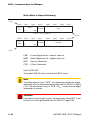
Service Data Objects (SDOs)
A Service Data Object (SDO) reads from entries or writes to entries
of the Object Dictionary.
The SDO transport protocol allows transmitting objects of any size.
The first byte of the first segment contains the necessary flow
control information including a toggle bit to overcome the problem
of doubly received CAN frames. The next three bytes of the first
segment contain index and sub-index of the Object Dictionary entry
to be read or written. The last four bytes of the first segment are
available for user data. The second and the following segments
(using the very same CAN identifier) contain the control byte and up
to seven bytes of user data. The receiver confirms each segment or
a block of segments, so that a peer-to-peer communication (client/
server) takes place.
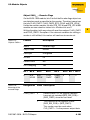
Process Data Objects (PDOs)
Process Data Objects (PDOs) are mapped to a single CAN frame
using up to 8 bytes of the data field to transmit application objects.
Each PDO has a unique identifier and is transmitted by only one
node, but it can be received by more than one (producer/consumer
communication).
2-4
D301087 0308 - BL20 CANopen
CANopen
PDO transmissions
PDO transmissions may be driven by an internal event, by an
internal timer, by remote requests and by the Sync message
received:
2
Event- or timer-driven:
An event (specified in the device profile) triggers message transmission. An elapsed timer additionally triggers the periodically
transmitting nodes.
Remotely requested:
Another device may initiate the transmission of an asynchronous
PDO by sending a remote transmission request (remote frame).
Synchronous transmission:
In order to initiate simultaneous sampling of input values of all
nodes, a periodically transmitted Sync message is required.
Synchronous transmission of PDOs takes place in cyclic and
acyclic transmission mode. Cyclic transmission means that the
node waits for the Sync message, after which it sends its
measured values. Acyclically transmitted synchronous PDOs are
triggered by a defined application-specific event.
D301087 0308 - BL20 CANopen
2-5
Short description of CANopen
Special Function Objects
CANopen also defines three specific protocols for synchronization,
emergency indication, and time-stamp transmission.
Synchronization object (Sync)
The Sync Object is broadcast periodically by the Sync Producer.
The time period between Sync messages is defined by the
Communication Cycle Period, which may be reset by a configuration tool to the application devices during the boot-up
process. There can be a time jitter in transmission by the Sync
Producer due to some other objects with higher prior identifiers
or by one frame being transmitted just before the Sync message.
The Sync message is mapped to a single CAN frame with the
identifier 128 by default. The Sync message does not carry any
data.
Emergency object (Emcy)
The Emergency message is triggered by the occurrence of a
device internal error situation and are transmitted from an Emergency producer on the concerned application device. This
makes them suitable for interrupt type error alerts. An Emergency message is transmitted only once per ‘error event’. As
long as no new errors occurs on a device, no further Emergency
message can be transmitted. Zero or more Emergency
consumers may receive these. The reaction of the Emergency
consumer is application-specific. CANopen defines several
Emergency Error Codes to be transmitted in the Emergency
message, which is a single CAN frame with 8 data byte.
Time stamp object (Time)
By means of Time-Stamp, a common time frame reference is
provided to application devices. It contains a value of the type
Time-of-Day. This object transmission follows the producer/
consumer push model. The associated CAN frame has the predefined identifier 256 and a data field of 6-byte length.
2-6
D301087 0308 - BL20 CANopen
BL20 and CANopen
BL20 and CANopen
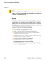
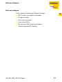
BL20 supports the following CANopen functions:
2
SDO transfer, any length of information
Emergency object
Sync frame evaluation
Event-driven PDOs
Synchronous PDOs (clock-synchronous)
Remote-requested PDO/polling
D301087 0308 - BL20 CANopen
2-7
Short description of CANopen
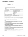
Electronic data sheet – EDS file
CANopen nodes are embedded in the CANopen structure by the
help of a standardized EDS file (Electronic Data Sheet).
The EDS file lists all necessary Objects with their corresponding
Sub-indices and the matching entries.
The latest version of a particular EDS file can be downloaded
directly from the TURCK Homepage www.turck.com.
2-8
D301087 0308 - BL20 CANopen
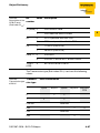
3
BL20 - Gateway for CANopen
Introduction ....................................................................................... 2
Function............................................................................................. 3
Technical Information........................................................................ 4
Technical Data................................................................................... 6
General Technical Data ...............................................................................6
– Relating to a Station ...............................................................................6
– Approvals .................................................................................................9
– Base Modules ........................................................................................10
Structure Diagram of a Gateway ...............................................................11
BL20-GW-CANOPEN ................................................................................11
Connections for data cables to BL20-GW-CANopen ....................... 16
Fieldbus connection via SUB-D socket.....................................................16
Fieldbus connection through direct wiring ................................................17
Connections of the data cables to BL20-GWBR-CANopen .............. 19
Fieldbus connection via Open Style connector.........................................19
Service Interface Connection ....................................................................22
– Connection with I/O-ASSISTANT-Connection Cable ............................22
Setting the bit transfer rate through DIP-switches ......................... 24
Node-ID Setting ............................................................................... 26
Acceptance of the BL20 Station Configuration ............................... 28
Status Indicators/ Diagnostic Messages Gateway........................... 29
Diagnostic Messages via LEDs .................................................................29
D301087 0308 - BL20 CANopen
3-1
BL20 - Gateway for CANopen
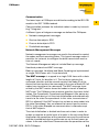
Introduction
This chapter contains a description of BL20 gateways for the standardized fieldbus CANopen. The chapter is divided up as follows: a
description of functions, general and specific technical data, a
description of addressing and status displays.
Attention
Please note, SWIRE-modules can only be used with the gateways
BL20-GW-CANOPEN with firmware version ≥ 4.02 and BL20GWBR-CANOPEN with firmware version ≥ 2.02.
Warning
The behavior of the analog inputs is now adapted to the actual CANopen standard DS401.
The firmware versions ≥ 4.02 for BL20-GW-CANOPEN and version
≥ 2.02 for BL20-GWBR-CANOPEN are thus not compatible with
older firmware versions relating to the behavior of the analog inputs.
3-2
D301087 0308 - BL20 CANopen
Function
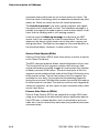
Function
The BL20 gateways enable BL20 modules to operate on CANopen.
The gateway is the connection between the BL20 modules and a
CANopen host system. It regulates the process data between the
I/O level and the fieldbus and generates diagnostic data for the
higher-level host system.
Information is made available to the software tool I/O-ASSISTANT
via the service interface.
D301087 0308 - BL20 CANopen
3-3
3
BL20 - Gateway for CANopen
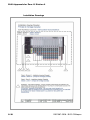
Technical Information
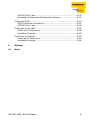
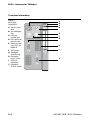
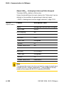
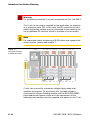
Figure 1:
BL20-GWCANOPEN
A Service interface
B Type designation
C LEDs for
module bus
D DIP-switch for
transfer rate
E Rotary encoding switch for
Node-ID
F SET button
G CANopen,
SUB-D plug
H CANopen,
direct wiring
I LEDs for
CANopen
J CANopen,
SUB-D socket
3-4
Bit Rate
GWBRCANOPEN
1
2
3
4
A
B
C
D
E
H
L
F
G
CAN H
SHLD
H
CAN L
GND
CAN H
SHLD
ERR
BUS
I
J
CAN L
GND
D301087 0308 - BL20 CANopen
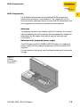
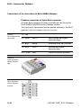
Technical Information
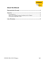
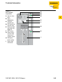
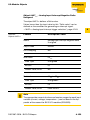
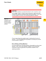
Figure 2:
BL20-GWBRCANOPEN
A Service interface
B Type
designation
C LEDs for
module bus
D DIP-switch for
transfer rate
E Rotary encoding switch for
Node-ID
F SET button
G Screw terminals for field
supply and
system supply
H CANopen,
direct wiring
I Open Style
connector
Bit Rate
GWBR
CANopen
1
2
3
4
A
B
C
D
3
E
H
L
F
G
ERR
BUS
H
CAN_H
Shield
I
CAN_L
GND
D301087 0308 - BL20 CANopen
3-5
BL20 - Gateway for CANopen
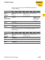
Technical Data
General Technical Data
Relating to a Station
Note
The auxiliary power supply must comply with the stipulations of
SELV (Safety Extra Low Voltage) according to IEC 364-4-41.
Table 1:
General technical
data (station)
Supply voltage/ auxiliary voltage
Nominal value (provision for
other modules)
24 V DC
Permissible range
according to EN 61131-2
(18 to 30 V DC)
Residual ripple
according to EN 61131-2
Potential isolation
Yes, via optocoupler
Ambient conditions
Ambient temperature
3-6
– TAmbient
0 to +55 °C / 32 to 131 °F
– TStore
-25 to +85 °C / 13 to 185 °F
Relative humidity
according to IEC 61 131-2/
EN 50 178
Climatic tests
according to IEC 61131-2
Noxious gas
– SO2:
10 ppm (rel. humidity
< 75 %, non-condensing)
– H2S:
1.0 ppm (rel. humidity
< 75 %, non-condensing)
D301087 0308 - BL20 CANopen
Technical Data
Resistance to vibration according to IEC 61131-2
10 to 57 Hz, Constant
amplitude 0.075 mm /
0.003 inch, 1g
Yes
57 to 150 Hz, Constant
acceleration 1 g
Yes
Mode of vibration
Frequency sweeps with a
change in speed of
1 Octave/min
Period of oscillation
20 frequency sweeps per axis
of coordinate
3
Shock resistant according to
IEC 68-2-27
18 shocks, sinusoidal halfwave 15 g peak value/11 ms,
in each case in +/- direction
per space coordinate
Resistance to repetitive shock
according to IEC 68-2-29
1 000 shocks, half-sinus 25 g
peak value/6 ms, in each case
in +/- direction per space
coordinate
Topple and fall according to IEC 68-2-31 and free fall according
to IEC 68-2-32
Weight
< 10 kg
Height of fall
1.0 m / 39.37 inch
Weight
10 to 40 kg
Height of fall
0.5 m / 19.69 inch
Test runs
7
Device with packaging, electrically tested printed-circuit board
D301087 0308 - BL20 CANopen
3-7
BL20 - Gateway for CANopen
Electromagnetic compatibility (EMC) according to
EN 50 082-2 (Industry)
Static electricity according to
EN 61 000-4-2
– Discharge through air (direct)
8 kV
– Relay discharge (indirect)
4 kV
Electromagnetic HF fields
10 V/m
according to EN 61 000-4-3 and
ENV 50 204
Conducted interferences
induced by HF fields according
to EN 61 000-4-6
10 V
Fast transients (Burst) according to EN 61 000-4-4
Interference criteria A: unre1 kV
stricted operation, normal operating behavior
2 kV
Interference criteria B: temporary interference, normal operation possible
Emitted interference according
to EN 50 081-2 (Industry)
according to EN 55 011 Class
A, Group 1
Reliability
Operational life MTBF
min. 120000 h
Electronic modules pull/
plug cycles
20
Tests according to EN 61 131-2
Cold
3-8
DIN IEC 68-2-1, temperature 25 °C / -13 °F, duration 96 h;
not in use
D301087 0308 - BL20 CANopen
Technical Data
Dry heat
DIN IEC 68-2-2, temperature
+85 °C / 185 °F, duration 96 h;
device not in use
Damp heat, cyclic
DIN IEC 68-2-30, temperature
+55 °C / 131 °F, duration 2
cycles every 12 h; device in
use
Temperature change
DIN IEC 68-2-14, temperature
0 to +55 °C / 32 to 131 °F,
duration 2 cycles, temperature
change per minute; device in
use
Pollution severity according to
IEC 664 (EN 61 131-2)
Protection class according to
IEC 529
IP20
Warning
This device can cause radio disturbances in residential areas and in
small industrial areas (residential, business and trading). In this case,
the operator can be required to take appropriate measures to suppress the disturbance at his own cost.
Approvals
Table 2:
Approvals
CE
CSA
UL
D301087 0308 - BL20 CANopen
3-9
3
BL20 - Gateway for CANopen
Base Modules
Table 3:
Protection class
IP 20
Technical data for
Measurement data according to VDE 0611 Part 1/8.92/
base modules
IEC 947-7-1/1989
Insulation stripping length
8 mm / 0.32 inch
Max. wire range
0.5 to 2.5 mm2 / 0.0008 to
0.0039 inch2 / 20 to 12 AWG
Crimpable wire
3-10
"e” solid core H 07V-U
0.5 to 2.5 mm2 / 0.0008 to
0.0039 inch2 / 20 to 12 AWG
"f” flexible core H 07V-K
0.5 to 1.5 mm2 / 0.0008 to
0.0023 inch2 / 20 to 16 AWG
"f” with ferrules according to
DIN 46228/1 (ferrules crimped
gas-tight)
0.5 to 1.5 mm2 / 0.0008 to
0.0023 inch2 / 20 to 16 AWG
Plug gauge according to
IEC 947-1/1988
A1
TOP connection technology
Tension clamp or screw
connection
D301087 0308 - BL20 CANopen
Technical Data
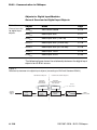
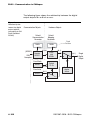
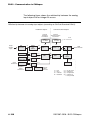
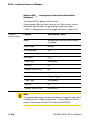
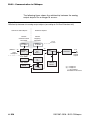
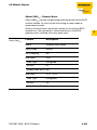
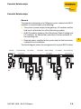
Structure Diagram of a Gateway
The BL20 CANopen gateway has the following structure:
Figure 3:
Gateway structure
Fieldbus
(External)
Service
interface
Controller
External RAM
– internal RAM
External
ROM flash
Module bus
(Internal)
– WDG
– CAN-Ctr.
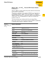
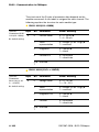
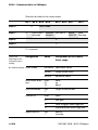
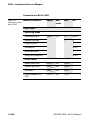
Technical Data BL20-GW-CANOPEN
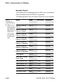
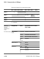
Table 4:
Technical data
BL20-GWCANOPEN
Designation
Value
Supply voltage(as per EN 61131-2)
Nominal value (supply from
bus refreshing module)
5 V DC (4.8 to 5.2 V DC)
Restriction on
EN 61131-2
The supply energy required to
bridge a supply interruption up
to 10 ms is not stored. Please
secure the Usys for
BL20-BR-24VDC-D modules by
using an appropriate power
supply unit!
Current drawn from the module bus
Without service/without
fieldbus
≈ 280 mA
Without service/with
fieldbus (1 Mbps)
≈ 410 mA
With service/without
fieldbus
≈ 300 mA
Maximum
≈ 350 mA
Dimensions
Width/length/height (mm)
D301087 0308 - BL20 CANopen
50.6 x 114.8 x 74.4 mm
3-11
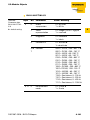
3
BL20 - Gateway for CANopen
Designation
Value
Service
Connections
PS/2 socket
Fieldbus terminations
1x 9-pole SUB-D socket,
1x 9-pole SUB-D plug, 2 x
tension spring connector type
LPZF, 5.08, 5-pole
Fieldbus shielding connection
via BL20-SCH-1
Transfer rate
10, 20, 50, 125, 250, 500, 800
and 1000 kbps
Fieldbus termination
SUB-D plug connector or
external resistors
2 rotary hex encoder
switches with labeling for the
Node-ID setting.
3-12
D301087 0308 - BL20 CANopen
Technical Data
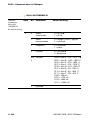
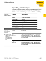
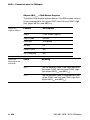
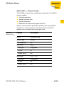
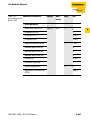
Technical Data BL20-GWBR-CANOPEN
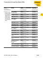
Table 5:
Technical data
BL20-GWBRCANOPEN
Designation
Value
Supply
3
Field supply
UL Nominal value
(range)
24 V DC (18 to 30 V DC)
IL max. field current
10 A
Isolation voltage (UL to 500Veff
USYS/
UL to fieldbus/UL to FE)
Connections
2-pole screw terminal
System supply
USYS nominal value
(range)
24 V DC (18 to 30 V DC)
ISYS (for IMB = 1.2 A/USYS max. 900 mA
= 18 V DC)
IMB (supply to the
module bus stations)
1.2 A
Isolation voltage (USYS 500Veff
to UL/
USYS to fieldbus/USYS to
FE)
Connections
2-pole screw terminal
Physical interfaces
Fieldbus
Transfer rate
10 kbps to 1 Mbps
Isolation voltage
(fieldbus to USYS/
fieldbus to UL/fieldbus
to FE)
500Veff
D301087 0308 - BL20 CANopen
3-13
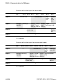
BL20 - Gateway for CANopen
Designation
Fieldbus connections
Value
Socket:
MSTBV 2,5/5-GF-5.08 GY AU/
Phoenix Contact
Plug:
TMSTBP 2,5/5-STF-5.08 AB GY AU/
Phoenix Contact (included in delivery)
Fieldbus shielding
connection
Via connector
Node-ID setting
2 rotary decimal encoding switches
Service
Connections
PS/2 socket
Warning
This device can cause radio disturbances in residential areas and in
small industrial areas (residential, business and trading). In this case,
the operator can be required to take appropriate measures to suppress the disturbance at his own cost.
3-14
D301087 0308 - BL20 CANopen
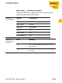
Connections for data cables to BL20-GW-CANOPEN
Connections for data cables to BL20-GW-CANOPEN
Fieldbus connection via SUB-D socket
SUB-D connectors are provided for communication with the BL20GW-CANOPEN gateway through the CANopen fieldbus.
The passive bus termination must be applied externally if the BL20
gateway is the last station in the bus structure. This external application can be implemented either through separate termination
resistors or through a special SUB-D plug which has an integrated
bus termination.
The pin assignments for the plug and socket are identical – the
socket is shown as an example:
Figure 4:
SUB-D socket on
the gateway (top
view)
5
4
9
Table 6:
Pin
Pin assignments
No.
for gateway SUBD plug/socket
1
A The shielding
of the fieldbus
is connected
through the
metal housing
of the SUB-D
connector and
the contact
with the mounting rails (see
Page 3-16)
3
8
2
7
1
6
Designation
Meaning
not used
2
CAN_L
inverted data signal (dominant low)
3
CAN_GND
ground (optional for CAN data signals)
4
not used
5
(CAN_SHLD) A
6
(GND)
7
CAN_H
8
not used
9
(CAN_V+)
D301087 0308 - BL20 CANopen
non-inverted data signal (dominant
high)
3-15
3
BL20 - Gateway for CANopen
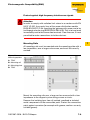
Fieldbus connection through direct wiring
For making connections to the fieldbus you can choose between a
SUB-D connection and direct wiring. Direct wiring of the BL20-GWCANOPEN to the CANopen fieldbus can be made through the two
terminal blocks with tension spring connectors.
The passive bus termination must be applied externally if the BL20
gateway is the last station in the bus structure.
Table 7:
Designation
List of connecting
CAN_L
leads for direct
wiring
Meaning
Inverted data signal (dominant low)
GND
Ground (optional)
SHLD
Shielding (see below)
CAN_H
Non-inverted data signal (dominant high)
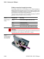
Attention
If the gateway is wired up directly, then the bus connection must be
shielded (e.g. with the help of a BL20-SCH-1 clamp).
Figure 5:
Shielding connection for an BL20GW-CANOPEN
3-16
D301087 0308 - BL20 CANopen
Connections for data cables to BL20-GW-CANOPEN
Attention
No compensating current should flow through the shielding.
To achieve this, a reliable system of equipotential bonding must be
installed.
Note
Equipotential bonding impedance ≤1/10 shielding impedance
D301087 0308 - BL20 CANopen
3-17
3
BL20 - Gateway for CANopen
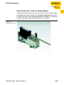
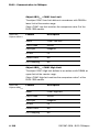
Connections of the data cables to BL20-GWBR-CANopen
Fieldbus connection via Open Style connector
An Open Style Connector (5-pole) is available for connecting the
BL20-GWBR-CANOPEN to the CANopen fieldbus.
The passive bus termination must be applied externally if the BL20
gateway is the last station in the bus structure.
Table 8:
1,2 - red
Pin assignment for
3,4 - white
the socket
CAN_H
Non-inverted data signal
(dominant high)
5,6 - grey
Shield,
Shielding braid, not insulated
7,8 - blue
CAN_L
Inverted data signal
(dominant low)
9,10 - black
GND
Ground reference (optional)
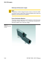
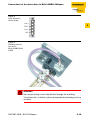
Figure 6:
Open Style connector (female/
top)
Figure 7:
Open Style connector (female/
bottom)
3-18
D301087 0308 - BL20 CANopen
Connections of the data cables to BL20-GWBR-CANopen
Figure 8:
Open Style connector (male)
CAN H
3
SHIELD
CAN L
GND
Figure 9:
Shielding connection for an
BL20-GWBR-CANOPEN
Attention
No compensating current should flow through the shielding.
To achieve this, a reliable system of equipotential bonding must be
installed.
D301087 0308 - BL20 CANopen
3-19
BL20 - Gateway for CANopen
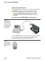
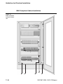
Service Interface Connection
The following cable can be used to connect the service interface
(female PS/2 connector) to a PC for the purpose of using
I/O-ASSISTANT (project planning and diagnostic software).
special I/O-ASSISTANT-connection cable from TURCK
(IOASSISTANT-ADAPTERKABEL-BL20/BL67; Ident-no.:
6827133)
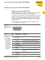
Connection with I/O-ASSISTANT-Connection Cable
Figure 10:
BL20-gateway
connected to PC
via special cable
b
B
c
C
A SUB-D socket
B BL20 connecting cable
C PS/2 plug
a
A
The I/O-ASSISTANT-cables have a PS/2 male connector (connection for female connector on gateway) and a SUB-D female
connector (connection for male connector on PC).
Figure 11:
PS/2 male connector on the connection cable to
the gateway (top
view)
3 4
2
5
1
3-20
6
D301087 0308 - BL20 CANopen
Connections of the data cables to BL20-GWBR-CANopen
Figure 12:
9-pole SUB-D
female connector
on the cable for
connecting to PC
(top view)
1
2
5
3
4
4
3
2
1
5
3
9
6
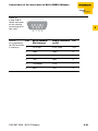
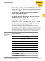
Table 9:
Pin
Pin assignments
for PS/2 and SUBD interfaces
1
8
7
7
8
6
9
BL20 gateway
PS/2 socket
SUB-D interface
on PC
Pin
+5 V Gw
DTR, DSR
4, 6
2
GND
GND
5
3
–
–
–
4
TxD
RxD
2
5
/CtrlMode
RTS
7
6
RxD
TxD
3
D301087 0308 - BL20 CANopen
3-21
BL20 - Gateway for CANopen
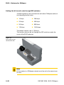
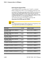
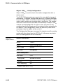
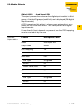
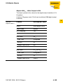
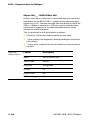
Setting the bit transfer rate through DIP-switches
The BL20 gateway can communicate with other CANopen nodes at
the following transfer rates:
10 kbps
250 kbps
20 kbps
500 kbps
50 kbps
800 kbps
125 kbps
1000 kbps
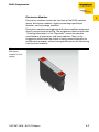
The default transfer rate is 125 kbps.
The transfer rate can be set through the DIP-switches under the
cover of the BL20 gateway.
Figure 13:
DIP-switch to set
the transfer rate
Note
All the nodes in a CANopen network must be set to the same transfer rate.
3-22
D301087 0308 - BL20 CANopen
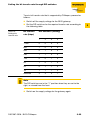
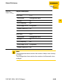
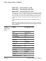
Setting the bit transfer rate through DIP-switches
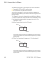
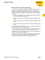
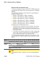
To set a bit transfer rate that is supported by CANopen, proceed as
follows:
Switch off the supply voltage for the BL20 gateway.
Set the DIP-switches for the required transfer rate according to
the following table:
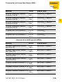
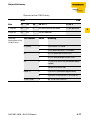
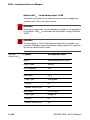
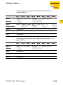
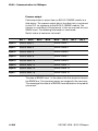
Table 10:
Setting the
transfer rate
Bit transfer
rate (kbps)
DIP-switches (setting)
1
2
3
4
1 000
0
0
0
0
800
1
0
0
0
500
0
1
0
0
250
1
1
0
0
125
0
0
1
0
50
1
0
1
0
20
0
1
1
0
10
1
1
1
0
reserved
x
x
x
1
Note
The DIP-switches are in the “1” position when they are set to the
right, as viewed from the front.
Switch on the supply voltage for the gateway again
D301087 0308 - BL20 CANopen
3-23
3
BL20 - Gateway for CANopen
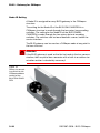
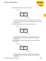
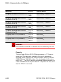
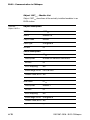
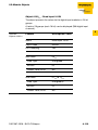
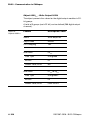
Node-ID Setting
A Node-ID is assigned to every BL20 gateway in the CANopen
structure.
The setting for the Node-ID of the BL20-GW-CANOPEN in a
CANopen structure is made through the two rotary hex encoding
switches. The setting for the Node-ID of the BL20-GWBRCANOPEN is made through the two rotary decimal encoding
switches. The switches can be found beneath a cover, below the
service interface.
The BL20 gateway can be used as a CANopen node at any point in
the bus structure.
Attention
If the BL20 gateway is used as the the last node in the bus communication, then a special bus connector with a built-in or add-on termination resistor is absolutely necessary!
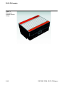
Figure 14:
Rotary hex encoding switch for the
CANopen address
setting of the
BL20-GW-CANOPEN
3-24
D301087 0308 - BL20 CANopen
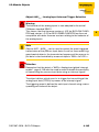
Node-ID Setting
Attention
A maximum of 127 Node-IDs (1 to 127) can be assigned in a
CANopen structure. Each Node-ID can only be assigned once in the
complete bus structure.
The Node-ID 000 must not be assigned. It is reserved for telegrams
that are directed to all the other bus nodes.
The rotary encoding switches are marked with H for High (more
significant digit) and L für Low (less significant digit).
BL20-GW-CANOPEN:
The L switch is used to set L X 160 (L = 0 to F).
The H switch is used to set L X 161 (H = 0 to F).
BL20-GWBR-CANOPEN:
The L switch is used to set L X 100 (L = 0 to 9).
The H switch is used to set L X 101 (H = 0 to 9).
Note
The NODE-ID switch on the BL20-GWBR-CANOPEN can be used
to assign Node-IDs from 1 to 99!
Note
After setting the Node-ID, the protective cover over the switches
must be closed again.
See Chapter 6, "Maximum System Extension", Page 6-2.
Note
BL20 does not support the assignment of Node-IDs across the bus
network.
D301087 0308 - BL20 CANopen
3-25
3
BL20 - Gateway for CANopen
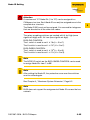
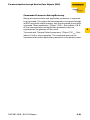
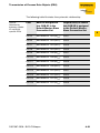
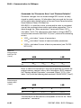
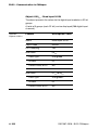
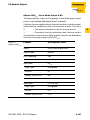
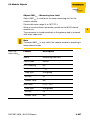
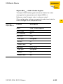
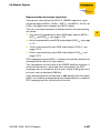
Acceptance of the BL20 Station Configuration
When making a new configuration of the BL20 station or an alteration of the existing station structure (“Module list”), the current
configuration must be accepted in the CANopen mirror of the BL20
gateway. This is done through the configuration button between the
two rotary encoding switches.
Note
The green "IOs" LED indicates that the current BL20 configuration
matches the stored reference module list.
Pressing the set button with a pointed object for at least 2 seconds
saves the current station configuration in non-volatile memory. A
hardware reset will then be carried out automatically. With this reset,
all the CANopen parameters will be restored to their default values,
if the newly saved configuration is different to the old one.
Attention
When saving the BL20 configuration, all the CANopen objects must
be parameterized again, if their parameter values differ from the default values. The complete parameterization of the station must subsequently be reloaded into the BL20 station.
The actuation of the button is indicated by a rapid (4 Hz) green
blinking of the "IOs" LED. After 2 seconds, the LED changes to
yellow blinking at 4 Hz, thus indicating that the station configuration
is being saved. When the storage procedure is completed, the LED
changes to a continuous green light.
3-26
D301087 0308 - BL20 CANopen
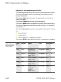
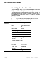
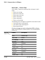
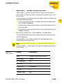
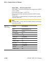
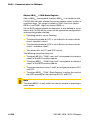
Status Indicators/ Diagnostic Messages Gateway
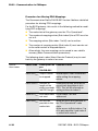
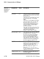
Status Indicators/ Diagnostic Messages Gateway
The gateway transmits the following diagnostics: the status of the
BL20 station, the communication via the internal module bus, the
communication to CANopen and the status of the gateway.
Diagnostic messages are displayed in two ways:
via individual LEDs
via the software of the respective host system (see Chapter 5,
Section “Diagnostics - Emergency Frames“, Page 5-1 ff.) or the
software-tool I/O-ASSISTANT
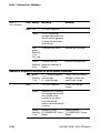
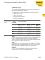
Diagnostic Messages via LEDs
Every BL20 gateway displays the following statuses via LEDs:
2 LEDs for module bus communication (module bus LEDs):
GW and IOs
2 LEDs for CANopen communication (fieldbus LEDs):
ERR and Bus
The LED diagnoses shown below apply to both gateway versions:
BL20-GW-CANOPEN
BL20-GWBR-CANOPEN
An additional diagnosis indication is shown for the BL20-GWBRCANOPEN.
D301087 0308 - BL20 CANopen
3-27
3
BL20 - Gateway for CANopen
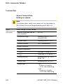
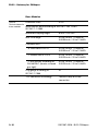
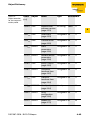
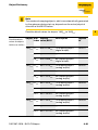
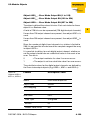
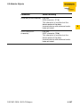
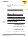
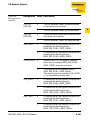
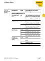
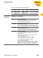
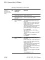
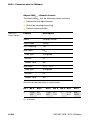
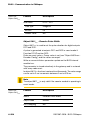
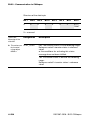
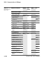
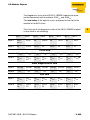
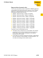
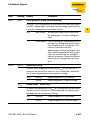
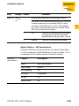
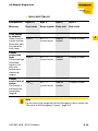
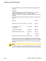
Table 11:
LED indicators
LED Status
Meaning
Remedy
GW
OFF
CPU not supplied.
Green
5 V DC operating
voltage is present; firmware is active; gateway
is ready for operation
and transfer
GW:
Firmware not active
green,
flashing,
1 Hz
IOs: red
Reload the firmware!
Green, Firmware active,
flashing, gateway hardware is
4 Hz
defect
Replace the gateway.
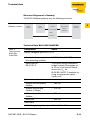
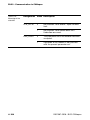
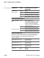
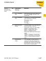
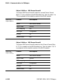
Additional diagnosis indication for BL20-GWBR-CANOPEN
GW
USYS: undervoltage or
green,
blinking, overvoltage
1 Hz
UL: undervoltage
Check that the supply
voltage is within the
permissible range.
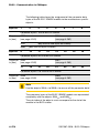
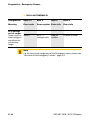
IOs
-
CPU not supplied.
Check the voltage
supply.
Green
Module bus is running, the configured module
bus station corresponds to the physically connected
station, communication
is active.
Green, Station is in the
flashing I/O-ASSISTANT Force
1 Hz
Mode.
3-28
Deactivate the
I/O-ASSISTANT Force
Mode.
D301087 0308 - BL20 CANopen
Status Indicators/ Diagnostic Messages Gateway
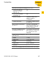
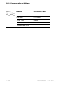
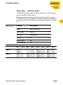
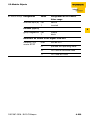
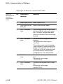
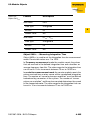
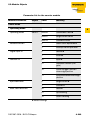
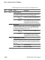
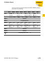
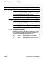
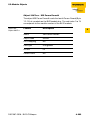
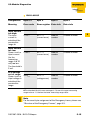
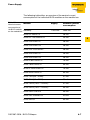
Table 11:
LED indicators
LED Status
Meaning
IOs
Controller is not ready, – Check wiring at the
VCC level is not within
gateway and the
the required range →
voltage supply.
possible reasons:
– Dismount modules
– too many modules
– Replace the gateway.
connected to the
gateway
– short circuit in
connected module
– hardware error in
– gateway
Red and
LED
"GW"
off
Remedy
Red
Non-adaptable modifi- – Compare the planned
flashing, cation of the physically
BL20 station with the
1 Hz
connected station.
physical station.
– Check the physical
station for defective or
incorrectly fitted electronics modules.
no module bus
Red
flashing, communication
4 Hz
At least one module has
to be plugged and has to
be able to communicate
with the gateway.
Red/
green
flashing,
1 Hz
Adaptable modification
of the physically
connected station;
data transfer possible
Check the physical
station for pulled or new
but not planned
modules.
Red
Automatic restart when
Short circuit or overload at sensor supply → debugging.
sensor supply is
switched off
Off
No voltage supply.
D301087 0308 - BL20 CANopen
Check the wiring of the
voltage supply.
3-29
3
BL20 - Gateway for CANopen
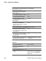
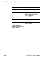
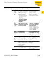
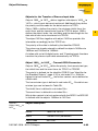
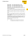
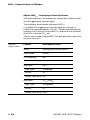
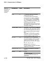
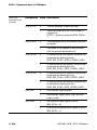
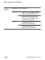
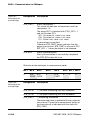
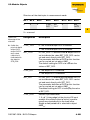
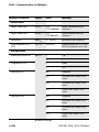
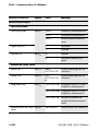
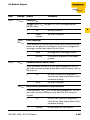
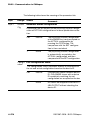
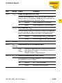
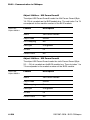
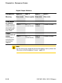
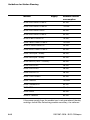
Table 11:
LED indicators
LED Status
Meaning
ERR Off
No errors in communi- –
cation between the
BL20-CANopen
gateway and other
CANopen nodes
Red
3-30
Remedy
Faulty or interrupted
– Check that the fieldbus
communication
ends with a termination
between BL20resistor, if the BL20CANopen gateway and
CANopen gateway is
other CANopen.
the last node in the bus
Possible causes:
topology.
– CAN-BusOff
– Check the seating of
– Heartbeat error
the CANopen bus
– Guarding error
connector (or the joints
– Transmit timeout
in the case of direct
wiring). All connections
must be correct and
properly seated.
– Check the CANopen
cable for possible
damage, and for
correct connections.
– Check that the correct
bit rate has been set.
– Check that the NMTmaster is still functioning properly.
D301087 0308 - BL20 CANopen
Status Indicators/ Diagnostic Messages Gateway
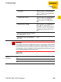
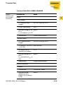
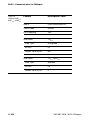
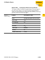
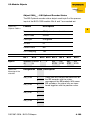
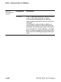
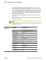
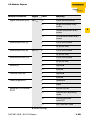
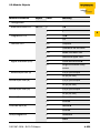
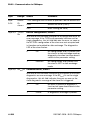
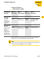
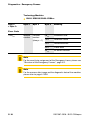
Table 11:
LED indicators
LED Status
Meaning
Remedy
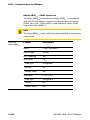
Bus OFF
Fieldbus not operating Wait until the firmware
download is finished.
If the download is
finished: hardware error;
replace the gateway.
red
NMT-slave state of the –
BL20-CANopen
gateway is "Stopped"
orange
NMT-slave state of the –
BL20-CANopen
gateway is "Pre-Operational"
green
NMT-slave state of the –
BL20-CANopen
gateway is "Operational"
Invalid Node-ID has
ERR red,
blinking been set
+
BUS alternately,
4 Hz
D301087 0308 - BL20 CANopen
Set the correct Node-ID
with the rotary hexadecimal or decimal encoding
switches.
3-31
3
BL20 - Gateway for CANopen
3-32
D301087 0308 - BL20 CANopen
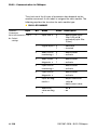
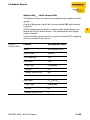
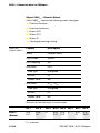
4
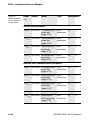
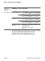
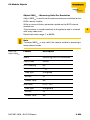
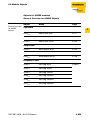
BL20 - Communication in CANopen
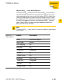
Setting up communication................................................................. 6
Minimum Boot-up .......................................................................................6
Identifier for the Standard Objects ............................................................10
– Node-ID .................................................................................................10
– COB-ID (Communication Object Identifier) ...........................................10
Set up Node Guarding Protocol ................................................................13
Boot-up Message......................................................................................15
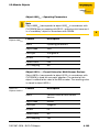
Parameterization through Service Data Objects (SDO).................... 16
Read (Read from Object Dictionary)..........................................................17
Write (Write to Object Dictionary) ..............................................................18
Commanded Parameter Storing/Restoring...............................................21
Transmission of Process Data Objects (PDO) .................................. 22
Communication Parameter COB-ID..........................................................22
Transmission Type ....................................................................................23
Inhibit Time ................................................................................................24
Event Timer ...............................................................................................24
Available PDOs..........................................................................................25
Mapping Objects in PDOs.........................................................................25
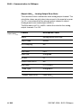
Default-PDOs and PDO-Mappings ...........................................................26
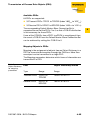
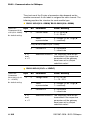
– Default-PDOs as per CiA DS-301 and DS-401 .....................................26
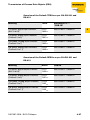
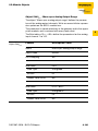
BL20-Specific Default-PDOs.....................................................................28
Mappable Objects .....................................................................................32
Procedure for Altering PDO-Mappings .....................................................34
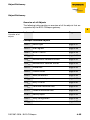
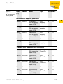
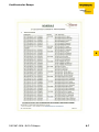
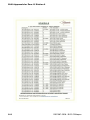
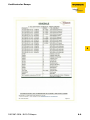
Object Dictionary ............................................................................. 35
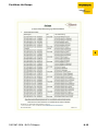
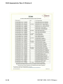
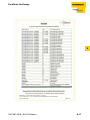
Overview of all Objects..............................................................................35
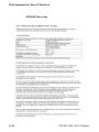
Commands for "Parameter Save" and "Restore Defaults" .......................40
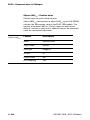
Objects for the Communication Profile .....................................................42
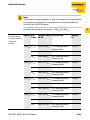
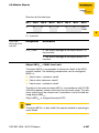
– Object 1000hex - Device Type ..............................................................47
– Object 1001hex - Error Register ............................................................48
– Object 1005hex - SYNC COB-ID ..........................................................49
– Object 1008hex - Device Name ............................................................51
– Object 1009hex - Manufacturer Hardware Version ...............................52
– Object 100Ahex - Manufacturer Software Version ................................53
– Object 100Chex - Guard Time ..............................................................53
– Object 100Dhex - Lifetime Factor .........................................................55
– Object 1010hex - Store Parameters ......................................................56
D301087 0308 - BL20 CANopen
4-1
BL20 - Communication in CANopen
– Object 1011hex - Restore Default Parameters ......................................58
– Object 1014hex - Emcy COB-ID ...........................................................60
– Object 1016hex - Consumer Heartbeat Time .......................................62
– Object 1017hex - Producer Heartbeat Time .........................................64
– Object 1018hex - Identity Object ..........................................................65
– Object 1020hex - Verify Configuration ..................................................68
– Object 1027hex - Module List ...............................................................70
Objects for the Transfer of Service Data ...................................................72
– Object 1200hex to 1203hex - Server SDO Default Parameters ............72
Objects for the Transfer of Process Output Data......................................74
– Object 1400hex to 141Fhex - Receive PDO Comm.
Default Parameters ................................................................................75
– Object 1600hex to 161Fhex - Receive PDO-Mapping Parameter ........79
Objects for the Transfer of Process Input data .........................................83
– Object 1800hex to 181Fhex - Transmit PDO-Parameters ......................83
– Object 1A00hex to 1A1Fh - Transmit PDO-Mapping Param. ...............89
Objects for Network Management ............................................................92
– Object 1F80hex - NMT Startup .............................................................92
– Object 1F81hex - Slave Assignment .....................................................94
– Object 1F82hex - Request NMT ............................................................98
– Object 1F83hex - Request Guarding ...................................................101
Manufacturer Specific Objects................................................................103
– Object 2000hex - Serial Number .........................................................103
– Object 2010hex - Reset Node Modifiers .............................................104
– Object 2400hex - System Voltages .....................................................108
– Object 2401hex - System Currents .....................................................109
I/O-Module Objects........................................................................ 110
Overview of the I/O-Module Objects.......................................................110
General I/O-Objects ................................................................................113
– Object 67FFh - Device Type ................................................................113
Objects for Digital Input Modules............................................................114
– General Overview for Digital Input Objects .........................................114
– Object 3064hex - XBI Param Dword ...................................................115
– Object 6000hex - Read Input 8 Bit ......................................................117
– Object 6020hex - Read Input Bit (1 to 128) .........................................118
– Object 6021hex - Read Input Bit(129 to 256) ......................................118
– Object 6022hex - Read Input Bit (257 to 288) .....................................118
– Object 6100hex - Read Input 16 Bit ....................................................119
– Object 6120hex - Read Input 32 Bit ....................................................120
Objects for Digital Output Modules.........................................................121
– General Overview for Digital Output Objects ......................................121
– Object 6200hex - Write Output 8 Bit .....................................................123
4-2
D301087 0308 - BL20 CANopen
– Object 6220hex - Write Output Bit (1 to 128) ......................................124
– Object 6221hex - Write Output Bit (129 to 256) ..................................124
– Object 6222hex - Write Output Bit (257 to 288) ..................................124
– Object 6300hex - Write Output 16 Bit .................................................125
– Object 6320hex - Write Output 32 Bit .................................................126
– Object 6206hex - Error Mode Output 8 Bit .........................................127
– Object 6207hex - Error State Output 8 Bit ..........................................128
– Object 6250hex - Error Mode Output Bit (1 to 128) ............................129
– Object 6251hex - Error Mode Output Bit (129 to 256) ........................129
– Object 6252hex - Error Mode Output Bit (257 to 288) ........................129
– Object 6260hex - Error State Output Bit (1 to 128) .............................131
– Object 6261hex - Error State Output Bit (129 to 256) .........................131
– Object 6262hex - Error State Output Bit (257 to 288) .........................131
– Object 6306hex - Error Mode Output 16 Bit .......................................133
– Object 6307hex - Error State Output 16 Bit ........................................134
– Object 6326hex - Error Mode Output 32 Bit .......................................135
– Object 6327hex - Error State Output 32 Bit ........................................136
Objects for Analog Input Modules...........................................................137
– General Overview for Analog Input Objects ........................................137
– Object 5420hex - Manu Spec Analog Input Range .............................139
– Object 6401hex - Read Analog Input 16 Bit ........................................144
– Object 6421hex - Analog Input Interrupt Trigger Selection ................146
– Object 6422hex - Analog Input Interrupt Source ................................148
– Object 6423hex - Analog Input Global Interrupt Enable .....................150
– Object 6424hex - Analog Input Interrupt Upper Limit Integer .............151
– Object 6425hex - Analog Input Interrupt Lower Limit Integer .............152
– Object 6426hex - Analog Input Interrupt Delta Unsigned ...................153
– Object 6427hex - Analog Input Interrupt Negative Delta Unsigned ....154
– Object 6428hex - Analog Input Interrupt Positive Delta Unsigned ......155
Objects for Analog Output Modules........................................................156
– General Overview for Analog Output Objects .....................................156
– Object 6411hex - Write Analog Output 16 Bit .....................................158
– Object 6443hex - Analog Output Error Mode .....................................159
– Object 6444hex - Analog Output Error State ......................................161
– Object 5440hex - Manu spec Analog Output Range ..........................162
Objects for RS232/RS4xx-Modules ........................................................164
– General Overview for RS232/RS4xx Objects ......................................164
– Object 5600hex – RS232/RS4xx Parameters ......................................165
– Object 5601hex - RS232/RS4xx RxD ..................................................168
– Object 5602hex - RS232/RS4xx TxD ..................................................172
Objects for SSI-Modules .........................................................................176
– General Overview for SSI Objects .......................................................176
– Object 5801hex – Encoder Config ......................................................177
D301087 0308 - BL20 CANopen
4-3
4
BL20 - Communication in CANopen
– Object 5802hex – Encoder Status .......................................................180
– Object 5803hex – Encoder Flags ........................................................181
– Object 5804hex – Encoder Diag ..........................................................183
– Object 5805hex – SSI Native Status ...................................................185
– Object 5806hex – SSI Optional Encoder Status ..................................189
– Object 5808hex – Encoder Control .....................................................190
– Object 5840hex – SSI Diag Mapping ..................................................191
– Object 6800hex – Operating Parameters ............................................193
– Object 6810hex – Preset Values for Multi-Sensor Devices .................193
– Object 6820hex – Position Value .........................................................194
– Object 6B00hex – CAM State Register ...............................................195
– Object 6B01hex – CAM Enable Register .............................................196
– Object 6B02hex – CAM Polarity Register ............................................197
– Object 6B10hex – CAM1 Low Limit ....................................................198
– Object 6B20hex – CAM1 High Limit ....................................................198
Objects for Counter-Modules..................................................................199
– General Overview for Counter Objects ................................................199
– Object 5800hex – Encoder Basic ........................................................201
– Object 5801hex – Encoder Config ......................................................205
– Object 5802hex – Encoder Status .......................................................210
– Object 5803hex – Encoder Flags ........................................................212
– Object 5804hex – Encoder Diag ..........................................................215
– Object 5808hex – Encoder Control .....................................................220
– Object 5810hex - Encoder Load Prepare Value ..................................223
– Object 5811hex - Encoder Pulse Width ..............................................224
– Object 5820hex - Measuring Integration Time ....................................225
– Object 5821hex - Measuring Low Limit ..............................................227
– Object 5822hex - Measuring High Limit ..............................................228
– Object 5823hex - Measuring Units Per Revolution .............................229
– Object 6800hex – Operating Parameters ............................................230
– Object 6810hex – Load Value For Multi-Sensor Devices ....................230
– Object 6820hex – Position value for multi-sensor devices .................231
– Object 6B00hex – CAM State Register ...............................................232
– Object 6B01hex – CAM 1 Enable Register ..........................................235
– Object 6B02hex – CAM Polarity Register ............................................236
– Object 6B10hex – CAM1 Low Limit ....................................................237
– Object 6B20hex – CAM1 High Limit ....................................................238
– Object 6B30hex - CAM1 Hysteresis ....................................................240
– Object 6C00hex - Area State Register ................................................241
– Object 6C01hex - Work Area Low Limit ..............................................243
– Object 6C02hex - Work Area High Limit .............................................244
– Object 6D00hex - Operating Status ....................................................245
4-4
D301087 0308 - BL20 CANopen
– Object 6D01hex - SingleTurn resolution (rotary),
Measuring step (linear) ........................................................................245
– Object 6D02hex - Number of distinguishable revolutions ...................245
– Object 6FFFhex - Device Type ............................................................245
– Parameters of BL20-1CNT ..................................................................246
– Parameter list for the counter module .................................................249
Objects for SWIRE modules....................................................................255
– General Overview for SWIRE Objects .................................................255
Representation of process input data .....................................................257
– Process input .......................................................................................258
Representation of process output data...................................................261
– Process output ....................................................................................262
– Representation of diagnostics data .....................................................264
– Object 3044hex - XBI Diag Dword ......................................................265
– Object 3045hex - XBI Diag Dword2 ....................................................266
– Representation of parameter data .......................................................267
– Object 3064hex - XBI Param Dword ...................................................269
– Object 3065hex - XBI Param Dword2 .................................................269
– Object 3066hex - XBI Param Dword3 .................................................270
– Object 3067hex - XBI Param Dword4 .................................................270
– Object 3068hex - XBI Param Dword5 .................................................271
– Object 3069hex - XBI Param Dword6 .................................................271
D301087 0308 - BL20 CANopen
4-5
4
BL20 - Communication in CANopen
Setting up communication
Minimum Boot-up
BL20 supports the Minimum Boot-up function described in
CiA DS-301.
Table 1:
Meaning of the
abbreviations
4-6
Abbreviation
Meaning
Explanation
cs
NMT command
specifier
A designation label for the
required service
Node-ID
Node identifier
Identifier for the node; an identification byte that is set
through the rotary decimal
encoding switches for the
CAN node. Possible values for
CANopen are 01hex to 7Fhex (1
to 127).
D301087 0308 - BL20 CANopen
Setting up communication
Booting with the Minimum Boot-up function is the typical application option for CANopen, and runs according to the following state
diagram:
Figure 1:
Boot procedure
with Minimum
Boot-up
Power on or hardware reset
1
4
Initialization state
2
11
14
Pre-Operational state
4
5
7
10
13
Stopped state
3
6
8
12
9
Operational state
1 Power-on (automatic change of state to the "Initialization" condition)
2 Initialization Finished (automatic change of state to "Pre-Operational")
3 Start Remote Node (start the CAN node)
4 Enter Pre-Operational (change over to "Pre-Operational")
5 Stop Remote Node (stop the CAN node)
6 Start Remote Node (start the CAN node)
7 Enter Pre-Operational (change to "Pre-Operational")
8 Stop Remote Node (stop the CAN node)
9 Reset Node (reset the complete CAN node)
10 Reset Node (reset the complete CAN node)
11 Reset Node (reset the complete CAN node)
12 Reset Communication (reset communication for the CAN node)
13 Reset Communication (reset communication for the CAN node)
14 Reset Communication (reset communication for the CAN node)
D301087 0308 - BL20 CANopen
4-7
BL20 - Communication in CANopen
The following messages are exchanged in the states mentioned:
Operational: PDO and SDO communication
Pre-Operational: only SDO communication
The services listed above (1 to 14) are required by CANopen or
performed independently by the nodes in order to change from one
state to another.
The "Stopped" state can be skipped when using Minimum Boot-up.
1 Power-on (automatic change of state to the "Initialization" state)
2 Initialization finished (automatic change of state to the "PreOperational" state)
3, 6 Start Remote Node (start the CAN node)
Master
Byte 0
Byte 1
cs = 1
NodeID
COB-ID = 0
Slave
The internal change of state of the CANopen slave now requires
a pause of at least 20 ms, before another request may be made
by the master.
4, 7 Enter Pre-Operational (change over to "Pre-Operational")
Master
Byte 0
Byte 1
cs = 128
NodeID
COB-ID = 0
Slave
The internal change of state of the CANopen slave now requires
a pause of at least 20 ms, before another request may be made
by the master.
4-8
D301087 0308 - BL20 CANopen
Setting up communication
5, 8 Stop Remote Node (stop the CAN node)
Master
Byte 0
Byte 1
cs = 2
NodeID
4
COB-ID = 0
Slave
The internal change of state of the CANopen slave now requires
a pause of at least 20 ms, before another request may be made
by the master.
9, 10, 11 Reset Node (reset the complete CAN node)
Master
Byte 0
Byte 1
cs = 129
NodeID
COB-ID = 0
Slave
The execution of this command is confirmed by a boot-up
message. This is in the form of a guard frame with the data
contents 00hex.
12, 13, 14 Reset Communication (reset communication for the
CAN node)
Master
Byte 0
Byte 1
cs = 130
NodeID
COB-ID = 0
Slave
The execution of this command is confirmed by a boot-up
message. This is in the form of a guard frame with the data
contents 00hex.
D301087 0308 - BL20 CANopen
4-9
BL20 - Communication in CANopen
Identifier for the Standard Objects
Node-ID
The identifier for each device in a CANopen network is the Node-ID.
The CANopen slaves can be assigned the Node-IDs 1 to 127
("Node-ID Setting", page 3-24).
COB-ID (Communication Object Identifier)
The identifier for each communication object in a CANopen network
is the COB-ID.
The COB-IDs for the standard objects (digital input, digital output,
analog input, analog output) are assigned automatically.
The ranges for the COB-IDs are defined by the "Predefined MasterSlave Connection Set".
Each range for the COB-IDs has 127 numerical values.
The COB-IDs are calculated according to the following rule:
COB-ID = Base-ID + Node-ID
Base-ID (decimal): 128; 384; 512; 640; 768; 896; 1024; 1152;
1280; 1408; 1536; 1792
Node-ID (decimal): 1 to 127
Table 2:
Identifiers for
basic objects
COB-ID
dec.
hex.
0
000hex
Function
Application
Network Management
(NMT)
Broadcast object
01 to 127 001hex to free
07Fhex
4-10
128
080hex
Synchronization (SYNC)
129 to
255
081hex to Emergency Message
0FFhex
256
100hex
257 to
384
101hex to free
180hex
Timestamp
Broadcast object
Message Broadcast object
D301087 0308 - BL20 CANopen
Setting up communication
Table 2:
Identifiers for
basic objects
COB-ID
Function
dec.
hex.
385 to
511
181hex to Transmit PDO 1
1FFhex
512
200hex
513 to
639
201hex to Receive PDO 1
27Fhex
640
280hex
641 to
767
281hex to Transmit PDO 2
2FFhex
768
300hex
769 to
895
301hex to Receive PDO 2
37Fhex
896
380hex
897 to
1023
381hex to Transmit PDO 3
3FFhex
1024
400hex
1025 to
1151
401hex to Receive PDO 3
47Fhex
1152
480hex
1153 to
1279
481hex to Transmit PDO 4
4FFhex
1280
500hex
1281 to
1407
501hex to Receive PDO 4
57Fhex
1408
580hex
1409 to
1535
581hex to Transmit SDO
5FFhex
1536
600hex
D301087 0308 - BL20 CANopen
Application
Digital input
4
free
Digital output
free
Analog input
free
Analog output
free
Analog input
free
Analog output
free
Analog input
free
Analog output
free
free
4-11
BL20 - Communication in CANopen
Table 2:
Identifiers for
basic objects
4-12
COB-ID
Function
Application
dec.
hex.
1537 to
1663
601hex to Receive SDO
67Fhex
1664 to
1772
680hex to free
6EChex
1793 to
1919
701hex to NMT Error (Node
77Fhex
Guarding, Heartbeat,
Boot-up)
1920 to
2014
800hex to free
7DEhex
2015 to
2031
7DFhex to NMT, LMT, DBT
7EFhex
D301087 0308 - BL20 CANopen
Setting up communication
Set up Node Guarding Protocol
Note
Further information on Node Guarding can be found in CiA DS-301.
Node Guarding is the name for the monitoring of network nodes by
a network manager.
In addition, the CANopen network nodes check that their network
manager is operating correctly and that the network is functioning
reliably.
In the default state, Node Guarding is inactive. To activate the Node
Guarding protocol for a node, various parameters must be set for
the Object Dictionary:
[100C] = Guard time
Given in milliseconds; the query interval (polling) that is to be
expected by the network slave
Default = 0
[100D] = Lifetime factor
This factor, multiplied by the Guard time, is the time that should
elapse after a Node Guarding protocol error before the network
slave generates an error message via EMCY. In this way, a
temporary communication problem, such as may be caused by
heavy bus loading, can be bridged without a Guarding Error.
Default = 0
Guard-ID
This is fixed and cannot be changed.
Guarding is initiated with the first Guard-Remote frame (GuardingRTR) from the CANopen network manager.
The Guarding Frame of the network manager has the COBID
"1793 - 1 + Node-ID" and does not have a data field.
Furthermore, the RTR bit in the message header must be set and the
Data Length code = 1.
D301087 0308 - BL20 CANopen
4-13
4
BL20 - Communication in CANopen
The node answers the telegram sent out by the network manager
within the preset time (Guard time) in the "Operational" state, with
the data contents 5. The gateway answers the next polling query
with the contents 133. The following response from the gateway is
with 5 again, and so on. This means that the gateway changes the
state of the most significant bit after every query (i.e. the bit is
toggled).
If the node is in the "Pre-Operational" state, then the value of the
data contents of the response telegram toggles between 127 and
255. If the node is in the "Stop" state, the value toggles between 4
and 132.
If there is no query from the network manager within the preset time,
then the gateway changes to the state "Guard Fail". If output
modules are fitted in the BL20 station, then their outputs will be put
into defined states, depending on the objects "Error mode output"
and "Error state output", or will retain the last state that was
received. Any RxPDOs that are received will still be processed and
output again. If the Guarding starts up again, the BL20 gateway
leaves the "Guard Fail" state, but remains in the Pre-Operational
state.
A "Start Node" command must be generated by the network
manager in order to restart the BL20 gateway (see CiA DS-301).
If the setting is Guard time = 0, then "passive Guarding" will occur.
This means that the gateway answers the Guard Remote frames,
without starting its own internal Guard timer and without changing
into the "Guard fail" state.
As an alternative to Node-/Life-Guarding, the Heartbeat mechanism
newly introduced with DS301 V4.0 is supported, which, unlike
Guarding, does not require Remote frames.
4-14
D301087 0308 - BL20 CANopen
Setting up communication
Boot-up Message
After initialization (after Power-On, Reset-Node and Reset-Communication), a Boot-up message as per CiA DS-301 V4.0 is sent out.
This is in the form of a guard frame with the contents 00hex.
Under certain circumstances, a network manager may fail to detect
a short drop-out of an BL20 gateway (for example, as a result of
voltage variations). This could occur under the following conditions:
The drop-out and initialization of the gateway happen in the time
between two Guarding-Frames
The gateway was already in the Pre-Operational state beforehand
The last state of the toggle bit was 1
If a Boot-up message is sent out after a reset or initialization, then
the drop-out mentioned above will also not be missed by the
network manager.
D301087 0308 - BL20 CANopen
4-15
4
BL20 - Communication in CANopen
Parameterization through Service Data Objects (SDO)
SDO (= Service Data Object) is a confirmed CANopen service that is
primarily used for parameterization and configuration of the
CANopen slaves (BL20) and less frequently for transmitting process
data. "Confirmed" means that an BL20-CANopen gateway (SDO
server) that is addressed by this procedure must acknowledge it
through a response. In this way, the SDO client obtains information
about whether the BL20 gateway that it addressed was contacted,
and whether the access was achieved without any errors (error code
in the response from the SDO server). SDO access means that the
contents of the Object Dictionary entries for an SDO server can be
read or written, and that the settings for a BL20 station can be made
in this way.
Four parallel SDO servers are supported. There are three "additional" SDOs, as well as the default SDO. As a default, these are
inactive, but can be parameterized and enabled through the Object
Dictionary entries 1201hex to 1203hex.
The communication parameters for the default SDO follow the
Predefined Connection Set, and cannot be modified (see CiA DS301, V4.01)
In the following representations of the messages, the identifier of the
CANopen message that is to be sent can be found below the frame,
and the contents of the data byte to be transmitted are within the
frame.
The following representations use the Expedited SDO Transfer, i.e.
a maximum of 4 bytes of user data can be transferred within one
telegram.
Note
CANopen also offers the possibility of segmented SDO-transfer of
data with data length of more than 4 bytes.
4-16
D301087 0308 - BL20 CANopen
Parameterization through Service Data Objects (SDO)
Read (Read from Object Dictionary)
Client
Byte 0
CCS =
40h
Byte 1
Byte 2
Byte 3
Byte 4
Byte 5
Byte 6
Byte 7
Index
Sub-Index
lsb
0
0
0
0
4
msb
COB-ID = 1537 + Node-ID - 1
Server
Byte 0
SCS =
4xh
Byte 1
Byte 2
Byte 3
Byte 4
Byte 5
Byte 6
Byte 7
Index
Sub-Index
lsb
Data
msb
COB-ID = 1409 + Node-ID - 1
Client
x... depending on the length of data read
LSB
= Least Significant bit →lowest value bit
MSB = Most Significant bit →highest value bit
SCS
= Server Command Specifier
CCS
= Client Command Specifier
(see CiA DS-301)
The stated COB-ID refers to the default SDO server.
Note
The BL20 gateway generates length information as to how many
data bytes are to be read (see CiA DS-301, Page 9-24 ff). This information is found in byte 0 "SCS = 4xh". The value x depends on the
length of data read.
D301087 0308 - BL20 CANopen
4-17
BL20 - Communication in CANopen
Write (Write to Object Dictionary)
Client
Byte 0
CCS =
2xh
Byte 1
Byte 2
Byte 3
Byte 4
Byte 5
Byte 6
Byte 7
Index
Sub-Index
lsb
Data
msb
COB-ID = 1537 + Node-ID - 1
Server
Byte 0
SCS =
60h
Byte 1
Byte 2
Byte 3
Byte 4
Byte 5
Byte 6
Byte 7
Index
Sub-Index
lsb
reserved
msb
COB-ID = 1409 + Node-ID - 1
Client
LSB
= Least Significant bit →lowest value bit
MSB = Most Significant bit →highest value bit
SCS
= Server Command
CCS
= Client Command
(see CiA DS-301)
The stated COB-ID refers to the default SDO server.
Note
The information in byte 0 "SCS " can optionally contain the length
information for the transmitted data bytes (see CiA DS-301, Page 921 ff). The information in byte 0 "SCS = 22hex" means that no length
information is present.
Attention
If an incorrect data length is given, the error code "Abort SDO Transfer Service" will be generated (see CiA DS-301, Page 9-26).
4-18
D301087 0308 - BL20 CANopen
Parameterization through Service Data Objects (SDO)
Table 3:
Abort codes for
errors in SDO
transfer
Abort code
Description
0503 0000hex
Toggle bit not altered.
0504 0001hex
Client server command specifier not valid
or unknown.
0601 0000hex
Unsupported access to an object.
0601 0001hex
Attempt to write a read only object.
0601 0002hex
Attempt to read a write only object.
0602 0000hex
Object does not exist in the object
dictionary.
06040041hex
Object cannot be mapped to the PDO.
06040042hex
The number and length of objects exceeds
PDO length.
06040043hex
General parameter incompatibility reason.
06040047hex
General internal incompatibility in the
device.
06070010hex
Data type does not match - wrong length.
0607 0012hex
Data type does not match- length too high.
0607 0013hex
Data type does not match- length too low.
06090011hex
Sub-index does not exist.
06090030hex
Value range of parameter exceeded.
06090031hex
Value range of parameter written too high.
06090032hex
Value range of parameter written too low.
06090036hex
Maximum value is less than minimum value.
08000000hex
Other error
08000020hex
Data cannot be stored to the application.
D301087 0308 - BL20 CANopen
4-19
4
BL20 - Communication in CANopen
Table 3:
Abort codes for
errors in SDO
transfer
Abort code
Description
08000021hex
Data cannot be stored to the app. because
of local control.
08000022hex
Data cannot be stored to the app. because
of device state.
Example:
Write a new COB-ID for RxPDO 1 (ID = 258hex)
Client
Byte 0
22h
Byte 1
Byte 2
Byte 3
Byte 4
Byte 5
1h
1400h
Byte 6
Byte 7
258h
COB-ID = 1537 + Node-ID - 1
Server
Byte 0
60h
Byte 1
Byte 2
1400h
Byte 3
Byte 4
Byte 5
1h
Byte 6
Byte 7
reserved
COB-ID = 1409 + Node-ID - 1
Client
4-20
D301087 0308 - BL20 CANopen
Parameterization through Service Data Objects (SDO)
Commanded Parameter Storing/Restoring
Saving of communication and application parameters is executed
by a command. This means that the parameters transferred through
an SDO are held in volatile memory, until they are saved by using the
command "Store parameters" (Object 1010hex, Sub-indices 0 to 3).
All the communication and application parameters that are
supported by the gateway will be saved.
The command "Restore Default parameters" (Object 1011hex, Subindices 0 to 3) is also supported. This command resets all the
communication and/or application parameters to the default values.
D301087 0308 - BL20 CANopen
4-21
4
BL20 - Communication in CANopen
Transmission of Process Data Objects (PDO)
CANopen provides PDO communication (PDO = Process Data
Object). PDOs are fast real-time process data that are handled as
unconfirmed services without a protocol overhead. PDOs can
contain a maximum of 8 bytes of data. They can be assembled and
configured by the user to suit the specific requirements. In addition,
there are a number of transmission/transfer settings (Transmission
types) for process data.
The following attributes can be set for each PDO through the object
"PDO communication parameter":
Communication Parameter COB-ID
The COB-ID is the CAN identifier that is used for the transmission of
a PDO (object 1400hex ff and 1800hex ff).
COB-IDs are used to define the priority of the message telegrams.
The lowest COB-ID has the highest priority.
For communication between 2 nodes, the COB-ID of the transmit
PDO must be the same as the COB-ID of the receive PDO.
Note
As delivered, each BL20 gateway has from none to eight active
PDOs, with COB-IDs that are taken from the Predefined MasterSlave Connection Set.
All other PDOs are inactive. This state can be seen from the invalid
bit (Bit 31) of the COB-ID.
4-22
D301087 0308 - BL20 CANopen
Transmission of Process Data Objects (PDO)
Transmission Type
The Transmission type determines under which circumstances a
PDO can be transmitted or received.
The following PDO Transmission types are supported by BL20:
Type 0 (sync, acyclic)
4
Type 1 (sync, cyclic)
Type 253 (remote request)
Type 255 (event-driven)
Table 4:
TransmisTransmission type sion type
of BL20
PDO transmission
cyclic
0
1
acyclic
×
×
synchr.
asynchr. only with
RTR
×
×
253
×
255
×
×
Type 0
The PDO will always be transmitted (TPDO) or evaluated (RPDO) if
this is permitted by a Sync-Frame transmitted by the SYNC
producer and the mapped contents of the BL20-CANopen gateway
have changed since the last transmission.
Type 1
Immediately after receiving each Sync-Frame, the BL20-CANopen
gateway puts out the mapped contents as a PDO on the network,
even if they have not changed since the last transmission.
Type 253
The PDO is only transmitted if a transmitted Remote-Frame
requests this from the BL20-CANopen gateway.
D301087 0308 - BL20 CANopen
4-23
BL20 - Communication in CANopen
Attention
The following Transmission type (Type 255) is only permissible for
TPDOs.
Type 255
In this mode of operation, the BL20-CANopen gateway does not
depend on any Sync or Remote-Request for PDO communication.
Whenever this is envisaged for an internal event within the BL20CANopen gateway, the gateway will transmit a PDO to the
CANopen network.
The Transmission types of the individual PDOs are independent,
which means that a freely mixed operation with synchronous and
asynchronous PDOs is possible.
Inhibit Time
The setting of an Inhibit time for the PDOs (Object 1800hex ff, SubIndex 03hex) is only supported for TPDOs. Unlike the other time
values, which are given as multiples of 1 ms, the Inhibit time is
defined as a multiple of 100 μs. However, since the time resolution
of the system clock in the BL20-CANopen gateway is 1 ms, Inhibit
time values below 10 x 100 μs are pointless.
Event Timer
The Event timer (Object 1800hex ff, Sub-Index 05hex) defines the
maximum interval after which a TPDO will be transmitted, even
though no event has occurred. This means that the Event timer
determines the maximum interval between two transmissions of a
TPDO.
The expiry of the interval set for the Event timer is detected as an
event. If any other event occurs, the Event timer is reset and
restarted.
The value of the object is interpreted as a multiple of 1 ms.
4-24
D301087 0308 - BL20 CANopen
Transmission of Process Data Objects (PDO)
Available PDOs
64 PDOs are supported:
32 Transmit PDOs: TPDO1 to TPDO32 (Index 1800hex to 181Fhex)
32 Receive PDOs: RPDO1 to RPDO32 (Index 1400hex to 141Fhex)
The corresponding Default Master-Slave Connection Set is
supported for each of the PDOs 1 to 4, so that a COB-ID distribution
is not necessary for these PDOs.
If one of the COB-IDs from xPDO1 to xPDO4 is reconfigured, then
the use of a COB-ID from the Default Master-Slave Connection Set
can be achieved by setting this COB-ID to 0.
Mapping Objects in PDOs
Mapping is the assignment of objects from an Object Dictionary in a
PDO for transmission/reception through the CAN-bus. More than
one object can be transmitted in a single PDO.
The Mapping parameters determine which items of information are
transmitted in a PDO:
Table 5:
Object Dictionary
for mapping
parameters
PDO
Type
Object Dictionary entries
Range
Range
Transmit-PDOs TPDO1 to
TPDO32
1A00hex to 1A1Fhex
Receive-PDOs
1600hex to 161Fhex
D301087 0308 - BL20 CANopen
RPDO1 to
RPDO32
4-25
4
BL20 - Communication in CANopen
Default-PDOs and PDO-Mappings
The 4 Transmit and 4 Receive-PDOs which are specified by the
Communication Profile CiA DS-301 are supported by BL20. The
mapping of these PDOs and their Transmission types are specified
by the I/O-Device Profile CiA DS-401.
Note
The Default-PDOs are only activated if the planned objects and subindices actually exist for the corresponding PDO. If, for instance, no
analog I/Os are used in a BL20 station, then the PDOs 2 to 4 are set
to "Invalid" and no mapping entries will be present.
In addition to the default PDOs which are standardized by the CiA
DS-301 and DS-401 profiles, other PDOs for an BL20-CANopen
gateway may be provided with mapping entries and communication
parameters. These additional PDOs (5 to 16) will be set to "Invalid"
as a default.
Default-PDOs as per CiA DS-301 and DS-401
The TPDOs in the following table have the following characteristics:
The COB-ID is part of sub-index 01hex
The PDO is active!
The first digit of the 8-digit hexadecimal COB-ID-number shows
amongst others, if the PDO is valid. Active PDOs are marked by
a hex-digit < 7. Normally, the digit is 0 or 4 →page 4-84.
4-26
D301087 0308 - BL20 CANopen
Transmission of Process Data Objects (PDO)
Overview of the Default-TPDOs as per CiA DS-301 and
DS-401
Meaning
TPDO
Sub-Index 01hex "COB-ID"
1st group, digital input channels,
(Bits 0 to 63)
PDO1
1800hex
0000 0180hex + Node-ID
1st group, analog input channels,
(Channel 0 to 3)
PDO2
1801hex
0000 0280hex + Node-ID
2nd group, analog input channels,
(Channel 4 to 7)
PDO3
1802hex
0000 0380hex + Node-ID
3rd group, analog input channels,
(Channel 8 to 11)
PDO4
1803hex
0000 0480hex + Node-ID
4
Overview of the Default-RPDOs as per CiA DS-301 and
DS-401
Meaning
RPDO
COB-ID
1st group, digital output channels,
(Bits 0 to 63)
PDO1
1400hex
0000 0200hex + Node-ID
1st group, analog output channels,
(Channel 0 to 3)
PDO2
1401hex
0000 0300hex + Node-ID
2nd group, analog output channels,
(Channel 4 to 7)
PDO3
1402hex
0000 0400hex + Node-ID
3rd group, analog output channels,
(Channel 8 to 11)
PDO4
1403hex
0000 0500hex + Node-ID
D301087 0308 - BL20 CANopen
4-27
BL20 - Communication in CANopen
BL20-Specific Default-PDOs
These additional PDOs are always set to "Invalid" as a default.
Before enabling these PDOs, the corresponding parameters must
be checked. This applies especially to the COB-IDs, since these are
taken from the Default Master-Slave Connection Set, and are
assigned to other Node-IDs. For this reason, other nodes with the
corresponding Node-ID must not be present in the network, or such
nodes must not use the corresponding COB-IDs.
The Transmission type of these PDOs is generally 255.
Overview of the BL20-specific TPDOs
Note
The COB-ID definition for the TPDOs depends on the gateway used
in the application (see EDS file for the gateways).
Meaning
TPDOs
COB-ID TPDO
2nd group, digital input channels
(Bits 64 to 127)
PDO5
1804hex
8000 01C0hex + Node-ID
3rd group, digital input channels
(Bits 128 to 191)
PDO6
1805hex
8000 02C0hex + Node-ID
4th group, digital input channels
(Bits 192 to 255)
PDO7
1806hex
C000 03C0hex + Node-ID
5th group, digital input channels
(Bits 256 to 319)
PDO8
1807hex
C000 04C0hex + Node-ID
1st group, encoders (Channels 0 + 1) PDO9
1808hex
C000 01E0hex + Node-ID
2nd group, encoders (Channels 2 + 3) PDO10
1809hex
C000 02E0hex + Node-ID
3rd group, encoders (Channels 4 + 5) PDO11
180Ahex
C000 03E0hex + Node-ID
4th group, encoders (Channels 6 + 7) PDO12
180Bhex
C000 04E0hex + Node-ID
4-28
D301087 0308 - BL20 CANopen
Transmission of Process Data Objects (PDO)
Meaning
TPDOs
COB-ID TPDO
4th group, analog input channels
(Channels 12 to 15)
PDO13
180Chex
C000 01A0hex + Node-ID
5th group, analog input channels
(Channels 16 to 19)
PDO14
180Dhex
C000 02A0hex + Node-ID
6th group, analog input channels
(Channels 20 to 23)
PDO15
180Ehex
C000 03A0hex + Node-ID
7th group, analog input channels
(Channels 24 to 27)
PDO16
180Fhex
C000 04A0hex + Node-ID
1st group, RS×× I/Os (Channel 0)
PDO18
1811hex
C000 0000hex
1st group, RS×× I/Os (Channel 1)
PDO19
1812hex
C000 0000hex
4
Overview of the BL20-specific RPDOs
Meaning
RPDOs
COB-ID RPDO
2nd group, digital output channels
(Bits 64 to 127)
PDO5
1804hex
8000 0240hex + Node-ID
3rd group, digital output channels
(Bits 128 to 191)
PDO6
1805hex
8000 0340hex + Node-ID
4th group, digital output channels
(Bits 192 to 255)
PDO7
1806hex
8000 0440hex + Node-ID
5th group, digital output channels
(Bits 256 to 319)
PDO8
1807hex
8000 0540hex + Node-ID
1st group, encoders (Channels 0 + 1) PDO9
1808hex
8000 0260hex + Node-ID
2nd group, encoders (Channels 2 + 3) PDO10
1809hex
8000 0360hex + Node-ID
3rd group, encoders (Channels 4 + 5) PDO11
180Ahex
8000 0460hex + Node-ID
D301087 0308 - BL20 CANopen
4-29
BL20 - Communication in CANopen
Meaning
RPDOs
COB-ID RPDO
4th group, encoders (Channels 6 + 7) PDO12
180Bhex
8000 0560hex + Node-ID
4th group, analog output channels
(Channels 12 to 15)
PDO13
180Chex
8000 0220hex + Node-ID
5th group, analog output channels
(Channels 16 to 19)
PDO14
180Dhex
8000 0320hex + Node-ID
6th group, analog output channels
(Channels 20 to 23)
PDO15
180Ehex
8000 0420hex + Node-ID
7th group, analog output channels
(Channels 24 to 27)
PDO16
180Fhex
8000 0520hex + Node-ID
1st group, RS×× I/Os (Channel 0)
PDO18
1811hex
8000 0000hex
1st group, RS×× I/Os (Channel 1)
PDO19
1812hex
8000 0000hex
Attention
The COB-IDs for the RS×××-Module must be defined by the user!
Example
The own Node-ID of an BL20-CANopen gateway is 1. There are
more than 12 analog input channels. As a result, appropriate
mapping entries are set up for TPDO13 (Object 1A0Chex), and the
COB-ID (Object 180C, Sub-Index 1) is pre-loaded with the value
8000 01A1hex. This PDO can only be enabled without alteration if a
node with the Node-ID 33 (own Node-ID + 32) does not exist, or at
least its TPDO1 is not used.
4-30
D301087 0308 - BL20 CANopen
Transmission of Process Data Objects (PDO)
The following table illustrates the systematic relationship:
Table 6:
Relationship
between a NodeID and BL20specific PDOs
PDO
Node-ID assigned to
this COB-ID in the
Default Master-Slave
Connection Set
Original PDO, to which
this COB-ID is assigned
in the Default MasterSlave Connection Set
PDO5
own Node-ID + 64 (40hex)
PDO1
PDO6
own Node-ID + 64 (40hex)
PDO2
PDO7
own Node-ID + 64 (40hex)
PDO3
PDO8
own Node-ID + 64 (40hex)
PDO4
PDO9
own Node-ID + 96 (60hex)
PDO1
PDO10
own Node-ID + 96 (60hex)
PDO2
PDO11
own Node-ID + 96 (60hex)
PDO3
PDO12
own Node-ID + 96 (60hex)
PDO4
PDO13
own Node-ID + 32 (20hex)
PDO1
PDO14
own Node-ID + 32 (20hex)
PDO2
PDO15
own Node-ID + 32 (20hex)
PDO3
PDO16
own Node-ID + 32 (20hex)
PDO4
4
D301087 0308 - BL20 CANopen
4-31
BL20 - Communication in CANopen
Mappable Objects
The maximum of 64 mapping entries per PDO that is specified by
Communication Profile CiA DS-301 is supported.
The following objects from the Object Dictionary can be mapped:
Table 7:
Name
Overview of
mappable objects
A Objects ×××1
and ×××2 will
be generated if
the number of
digital input or
output channels exceeds
the value 128
or 256 respectively.
4-32
Index
Sub-index
Direction
Dummy mapping
Boolean
0001hex
-
Receive
Dummy mapping
Boolean Integer8
0002hex
-
Receive
Dummy mapping
Boolean Integer16
0003hex
-
Receive
Dummy mapping
Boolean Integer32
0004hex
-
Receive
Dummy mapping
Boolean Unsigned8
0005hex
-
Receive
Dummy mapping
0006hex
Boolean Unsigned16
-
Receive
Dummy mapping
0007hex
Boolean Unsigned32
-
Receive
Error register
1001hex
–
Transmit
Manu Spec Analog
Input Range
5420hex
1 to n
Transmit
RS232/RS4xx RxD
5601hex
1 to n
Receive
RS232/RS4xx TxD
5602hex
1 to n
Transmit
Encoder status
5802hex
1 to n
Transmit
Encoder flags
5803hex
1 to n
Transmit
SSI Native status
5805hex
1 to n
Transmit
D301087 0308 - BL20 CANopen
Transmission of Process Data Objects (PDO)
Table 7:
Name
Overview of
mappable objects
A Objects ×××1
and ×××2 will
be generated if
the number of
digital input or
output channels exceeds
the value 128
or 256 respectively.
Index
Sub-index
Direction
SSI Optional
encoder status
5806hex
1 to n
Transmit
Encoder control
5808hex
1 to n
Receive
Read input 8 bit
6000hex
1 to n
Transmit
Read input bit
(1 to 128) A
6020hex
1 to n
Transmit
Read input 16 bit
6100hex
1 to n
Transmit
Read input 32 bit
6120hex
1 to n
Transmit
Write output 8 bit
6200hex
1 to n
Receive
Write output bit
(1 to 128) A
6220hex
1 to n
Receive
Write output 16 bit
6300hex
1 to n
Receive
Write output 32 bit
6320hex
1 to n
Receive
Read analog input
16 bit
6401hex
1 to n
Transmit
Write analog output
16 bit
6411hex
1 to n
Receive
Position Value for
Multi-Sensor
Devices
6820hex
1 to n
Transmit
CAM1 State register 6B00hex
1 to n
Transmit
6C00hex
1 to n
Transmit
Area State register
D301087 0308 - BL20 CANopen
4
4-33
BL20 - Communication in CANopen
Procedure for Altering PDO-Mappings
The Communication Profile CiA DS-301 Version 4 defines a detailed
procedure for altering PDO-mappings.
For the BL20 gateway, this results in the following method for modifying PDO-mappings:
The node state of the gateway must be "Pre-Operational".
The number of mapping entries (Sub-index 0) for a PDO must be
set to 0.
The mapping entries (Sub-index 1 to 64) can be written.
The number of mapping entries (Sub-index 0) must now be set
to the valid number of mapped objects.
Alternatively, the new mapping can be saved in non-volatile
memory (Store Communication parameters).
The following abort codes (Abort-Domain-Protocol) may be sent
back by the gateway in case of an error:
Table 8:
Abort codes
Abort code
Description as Possible cause
per
CiA DS-301
0604 0041hex Object cannot
be mapped
Invalid object-index transferred
while writing the mapping
entries.
0604 0042hex Number or
length of the
objects exceeds
the PDO length
Attempted to map too many or
excessively long objects to a
PDO. This will be returned on
writing to the sub-index 0.
0609 0011hex Sub-index does A sub-index > 64 was
not exist
addressed.
0800 0022hex Access not
possible in this
node state
4-34
Write access is only possible in
the "Pre-Operational" node
state.
Write access to Sub-indices 1 to
64 is only possible if sub-index 0
is written with value 0.
D301087 0308 - BL20 CANopen
Object Dictionary
Object Dictionary
Overview of all Objects
The following table provides an overview of all the objects that are
supported by the BL20 CANopen gateway.
4
Table 9:
Overview of all
objects
Index
Name
Page
CANopen Standard Objects
1000hex
Device type
page 4-47
1001hex
Error register
page 4-48
1005hex
SYNC COB-ID
page 4-49
1008hex
Device name
page 4-48
1009hex
Manufacturer hardware version
page 4-52
100Ahex
Manufacturer software version
page 4-53
100Chex
Guard time
page 4-53
100Dhex
Lifetime factor
page 4-55
1010hex
Store parameters
page 4-56
1011hex
Restore default parameters
page 4-58
1014hex
Emcy COB-ID
page 4-60
1016hex
Consumer heartbeat time
page 4-62
1017hex
Producer heartbeat time
page 4-64
1018hex
Identity object
page 4-64
1020hex
Verify configuration
page 4-68
1027hex
Module list
page 4-70
D301087 0308 - BL20 CANopen
4-35
BL20 - Communication in CANopen
Table 9:
Overview of all
objects
Index
Name
Page
1200hex
to
1203hex
Server SDO parameters
page 4-72
1400hex
to
141Fhex
Receive PDO Communication parameters
page 4-75
1600hex
to
161Fhex
Receive PDO-mapping parameters
page 4-79
1800hex
to
181Fhex
Transmit PDO-parameters
page 4-83
1A00hex
to
1A1Fhex
Transmit PDO-mapping parameters
page 4-89
1F80hex
NMT startup
page 4-92
1F81hex
Slave assignment
page 4-94
1F82hex
Request NMT
page 4-98
1F83hex
Request guarding
page 4-101
Manufacturer specific objects
4-36
2000hex
Serial number
page 4-103
2010hex
Behavior Modifiers
page 4-104
whex
System Voltages
page 4-108
2401hex
System Currents
page 4-109
D301087 0308 - BL20 CANopen
Object Dictionary
Table 9:
Overview of all
objects
Index
Name
Page
Objects for BL20 I/O-modules
5420hex
Analog Input Mode
page 4-139
5440hex
Analog Output Mode
page 4-161
5801hex
Encoder config
page 4-180
5802hex
Encoder status
page 4-180
5803hex
Encoder flags
page 4-181
5804hex
Encoder diag
page 4-183
5805hex
SSI Native status
page 4-185
5806hex
SSI Optional encoder
page 4-189
5808hex
Encoder control
page 4-190
6000hex
Read input 8 bit
page 4-117
6020hex
Read input bit 1 to 128
page 4-118
6021hex
Read input bit 129 to 256
page 4-118
6022hex
Read input bit 257 to 288
page 4-118
6100hex
Read input 16 bit
page 4-119
6120hex
Read input 32 bit
page 4-120
6200hex
Write output 8 bit
page 4-123
6206hex
Error mode output 8 bit
page 4-127
6207hex
Error value output 8 bit
page 4-128
6220hex
to
6222hex
Write output bit 1 to 128 to Write output
bit 257 to 288
page 4-124
6250hex
to
6252hex
Error mode output Bit 1 to 128 to Error
mode output Bit 257 to 288
page 4-129
D301087 0308 - BL20 CANopen
4-37
4
BL20 - Communication in CANopen
Table 9:
Overview of all
objects
4-38
Index
Name
Page
6260hex
to
6262hex
Error value output Bit 1 to 128 to Error
value output Bit 257 to 288
page 4-131
6300hex
Write output 16 bit
page 4-125
6306hex
Error mode output 16 bit
page 4-133
6307hex
Error value output 16 bit
page 4-134
6320hex
Write output 32 bit
page 4-126
6326hex
Error mode output 32 bit
page 4-135
6327hex
Error value output 32 bit
page 4-136
6401hex
Read Analog Input 16 bit
page 4-144
6411hex
Write analog Output 16 bit
page 4-157
6421hex
Analog input interrupt Trigger Selection
page 4-145
6422hex
Analog input interrupt source
page 4-148
6423hex
Analog input global interrupt enable
page 4-149
6424hex
Analog input interrupt upper limit Integer page 4-150
6425hex
Analog input interrupt lower limit Integer
page 4-151
6426hex
Analog input interrupt delta Unsigned
page 4-152
6427hex
Analog input interrupt negative delta
Unsigned
page 4-153
6428hex
Analog input interrupt Positive Delta
Unsigned
page 4-154
6443hex
Analog output error mode
page 4-157
6444hex
Analog output error value Integer
page 4-160
67FFhex
Device type
page 4-113
6800hex
Operating parameters
page 4-193
D301087 0308 - BL20 CANopen
Object Dictionary
Table 9:
Overview of all
objects
Index
Name
Page
6810hex
Preset value for multi-sensor devices
page 4-193
6820hex
Position value for multi-sensor devices
page 4-194
6B00hex
CAM State register
page 4-195
6B01hex
CAM Enable register
page 4-196
6B02hex
CAM Polarity register
page 4-197
6B10hex
CAM1 Low limit
page 4-198
6B20hex
CAM1 High limit
page 4-198
D301087 0308 - BL20 CANopen
4-39
4
BL20 - Communication in CANopen
Commands for "Parameter Save" and "Restore Defaults"
Parameter changes that are made through SDO access are only
stored in volatile memory. All alterations that are made by the user
will be replaced by default values at the next Reset Communication,
Reset Node or Power-ON-Boot-Up.
With BL20, it is possible to use a command to make a permanent
save of the communication and/or application parameters. This is
done through the "Store parameters" command (Object 1010hex
sub-index 1 to 3). The command is executed by using an SDO to
write the data contents 0x6576 6173 ("save") to one of the following
entries:
1010hex sub-index 1 saves all parameters
1010hex sub-index 2 saves all communication parameters
1010hex sub-index 3 saves all device parameters (see CiA DS301 V4.01)
Table 10:
Data contents
0x6576 6173
("save")
MSB
LSB
ASCII
e
v
a
s
HEX
65hex
76hex
61hex
73hex
Since in some circumstances it may not be possible to restore the
original memory contents after a lot of alterations, BL20 supports
the "Restore default Parameter" command (Object 1011hex subindex 1 to 3) with the following data contents: 0x6461 6F6C ("load").
Table 11:
Data contents
0x6461 6F6C
("load")
MSB
LSB
ASCII
d
a
o
l
HEX
64hex
61hex
6Fhex
6Chex
The division of the Sub-entries corresponds to that for the "Store
parameters" command.
4-40
D301087 0308 - BL20 CANopen
Object Dictionary
After the command "Restore default parameters", a Reset Node
must be carried out, followed by a "Store parameters" command.
The default values are only saved again when this last command is
executed.
4
D301087 0308 - BL20 CANopen
4-41
BL20 - Communication in CANopen
Objects for the Communication Profile
The following table provides an overview of the supported entries in
the Object Dictionary which are defined by the Communication
Profile CiA DS-301:
The column Index (hex) describes the position of the entry in the
Object Dictionary.
The column Object shows the Type of the object.
The column Name shows a predefined symbolic name for the entry.
The column Type shows the data type for the entry, as defined by
CiA DS-301.
The column Access shows the access options for the entry. These
are:
rw (read/write)
ro (read only)
const (constant) = a read-only constant
The column M/O shows whether the entry is mandatory or optional.
Table 12:
Object overview
for the communication profile
4-42
Index
(hex)
Object
Name
Type
Access M/O
1000hex VAR
Device type
(page 4-47)
Unsigned32 const
M
1001hex ARRAY
Error register
(page 4-48)
Unsigned8 ro
M
1005hex VAR
SYNC COB-ID
(page 4-49)
Unsigned32 rw
O
1008hex VAR
Device name
(page 4-51)
Vis-String
const
O
1009hex VAR
Manufacturer
hardware
version
(page 4-52)
Vis-String
const
O
D301087 0308 - BL20 CANopen
Object Dictionary
Table 12:
Object overview
for the communication profile
Index
(hex)
Object
100Ahex VAR
Name
Type
Manufacturer
Vis-String
software version
(page 4-53)
Access M/O
const
O
4
100Chex VAR
Guard time
(page 4-53)
Unsigned32 rw
O
100Dhex VAR
Lifetime factor
(page 4-55)
Unsigned32 rw
O
1010hex ARRAY
Store
parameters
(page 4-56)
Unsigned32 rw
O
1011hex ARRAY
Restore default
parameters
(page 4-58)
Unsigned32 rw
O
1014hex VAR
Emcy COB-ID
(page 4-60)
Unsigned32 rw
O
1016hex ARRAY
Consumer
heartbeat time
(page 4-62)
Unsigned32 rw
O
1017hex VAR
Producer
heartbeat time
(page 4-64)
Unsigned16 rw
O
1018hex RECORD Identity object
(page 4-64)
Identity
ro
O
1020hex ARRAY
Verify
configuration
(page 4-68)
Unsigned32 rw
O
1027hex ARRAY
Module list
(page 4-70)
Unsigned16 ro
M
D301087 0308 - BL20 CANopen
4-43
BL20 - Communication in CANopen
Table 12:
Object overview
for the communication profile
Index
(hex)
Object
Name
Type
Access M/O
SDO
parameter
ro
O
1201hex RECORD 2nd Server SDO SDO
parameter
parameter
(page 4-72)
rw
O
1202hex RECORD 3rd Server SDO
parameter
(page 4-72)
SDO
parameter
rw
O
1203hex RECORD 4th Server SDO
parameter
(page 4-72)
SDO
parameter
rw
O
1400hex RECORD 1st receive PDO PDO
parameter
CommPar
(page 4-75)
rw
O
1401hex RECORD 2nd receive PDO PDO
parameter
CommPar
(page 4-75)
rw
O
1402hex RECORD 3rd receive PDO PDO
parameter
CommPar
(page 4-75)
rw
O
...
...
...
...
PDO
CommPar
rw
O
Server SDO parameter
1200hex RECORD 1st Server SDO
parameter
(page 4-72)
Receive PDO communication parameter
...
...
141Fhex RECORD 32nd receive
PDO parameter
(page 4-75)
4-44
D301087 0308 - BL20 CANopen
Object Dictionary
Table 12:
Object overview
for the communication profile
Index
(hex)
Object
Name
Type
Access M/O
Receive PDO-mapping parameter
1600hex ARRAY
1st receive
PDO-mapping
(page 4-79)
PDO
mapping
rw
O
1601hex ARRAY
2nd receive
PDO-mapping
(page 4-79)
PDO
mapping
rw
O
1602hex ARRAY
3rd receive
PDO-mapping
(page 4-79)
PDO
mapping
rw
O
...
...
...
...
...
32nd receive
PDO-mapping
(page 4-79)
PDO
mapping
rw
O
...
161Fhex ARRAY
4
Transmit PDO communication parameter
1800hex RECORD 1st transmit
PDO parameter
(page 4-83)
PDO
CommPar
rw
O
1801hex RECORD 2nd transmit
PDO parameter
(page 4-83)
PDO
CommPar
rw
O
1802hex RECORD 3rd transmit
PDO parameter
(page 4-83)
PDO
CommPar
rw
O
...
...
...
...
PDO
CommPar
rw
O
...
...
181Fhex RECORD 32nd transmit
PDO parameter
(page 4-83)
D301087 0308 - BL20 CANopen
4-45
BL20 - Communication in CANopen
Table 12:
Object overview
for the communication profile
Index
(hex)
Object
Name
Type
Access M/O
Transmit PDO-mapping parameter
1A00hex ARRAY
1nd transmit
PDO-mapping
(page 4-89)
PDO
mapping
rw
O
1A01hex ARRAY
2nd transmit
PDO-mapping
(page 4-89)
PDO
mapping
rw
O
1A02hex ARRAY
3rd transmit
PDO-mapping
(page 4-89)
PDO
mapping
rw
O
...
...
...
...
...
32nd transmit
PDO mapping
(page 4-89)
PDO
mapping
rw
O
...
1A1Fhex ARRAY
NMT Master related Objects
4-46
1F80hex VAR
NMT startup
(page 4-92)
Unsigned32 rw
O
1F81hex ARRAY
Slave
assignment
(page 4-94)
Unsigned32 rw
O
1F82hex ARRAY
Request NMT
(page 4-98)
Unsigned8 rw
O
1F83hex ARRAY
Request
guarding
(page 4-101)
Unsigned8 rw
O
D301087 0308 - BL20 CANopen
Object Dictionary
Object 1000hex - Device Type
Object 1000hex contains the Type and the Function of the BL20
station.
The value FFFF 0191hex indicates that all Device Profiles are
supported.
4
Table 13:
Object 1000hex
Object description
INDEX
1000hex
Name
Device type
Object code
VAR
Data Type
Unsigned32
Value range
Access
ro
PDO-mapping
No
Value range
Unsigned32
Default value, BL20
FFFF 0191hex
D301087 0308 - BL20 CANopen
4-47
BL20 - Communication in CANopen
Object 1001hex - Error Register
Object 1001hex contains the Error register for the BL20-CANopen
gateway. It thus contains, in one byte, the internal errors that occur.
Table 14:
Object 1001hex
Object description
INDEX
1001hex
Name
Error register
Object code
VAR
Data Type
Unsigned8
Value range
Access
ro
PDO-mapping
Optional
Value range
Unsigned8
Default value, BL20
00hex
Error register
Bit 0
Bit 1
Bit 2
Bit 3
Bit 4
Bit 5
Bit 6
Bit 7
generic
current
voltage
0
Comm.
0
0
Manu.
Abbreviations:
Abbr.
generic
current.
voltage
Comm.
Manu.
4-48
Meaning
General error
Output short-circuit/
Current error
Voltage error
Communication error
Valid for Modules
all
DO, AI,TC
Manufacturer-specific
error
all
PF, DO, AI, AO
all
D301087 0308 - BL20 CANopen
Object Dictionary
Object 1005hex - SYNC COB-ID
Object 1005hex defines the COB-ID for the Synchronization Object
(SYNC). The BL20-CANopen gateway not generate SYNC
messages, only receive them.
Structure of the SYNC COB-ID entry (Unsigned32):
4
MSB
LSB
Bits
31
30
29
28 to 11
10 to 0
11-bit ID
×
0
0
00 0000 0000 0000 0000
11-bit identifier
29-bit ID
×
0
1
29-bit identifier
Table 15:
Bit
Value
Description of the number
SYNC COB-ID
entry
Description
31 (MSB) X
fixed
30
0
1
Module does not generate a SYNC message
Module generates a SYNC message
29
0
1
11-bit ID (CAN 2.0A) →for BL20
29-bit ID (CAN 2.0B)
28 to 11
0
X
if Bit 29 = 0
if Bit 29 = 1: Bits 28 to 11 of the SYNC-COBID
10 to 0
(LSB)
X
Bit 10 to 0 of the SYNC-COB-ID
Note
Bit 30 is static, i.e. cannot be changed.
D301087 0308 - BL20 CANopen
4-49
BL20 - Communication in CANopen
Table 16:
Object 1005hex
Object description
INDEX
1005hex
Name
COB-ID Sync
Object code
VAR
Data Type
Unsigned32
Value range
4-50
Access
rw
PDO-mapping
No
Value range
Unsigned32
Default value, BL20
0000 0080h
D301087 0308 - BL20 CANopen
Object Dictionary
Object 1008hex - Device Name
Object 1008hex contains the manufacturer-specific device name
Table 17:
Object 1008hex
Object description
INDEX
1008hex
Name
Device name from the
manufacturer
Object code
VAR
Data Type
Visible String
4
Value range
Access
const.
PDO-mapping
No
Value range, BL20
–
Default value, BL20
BL20-GW-CO
D301087 0308 - BL20 CANopen
4-51
BL20 - Communication in CANopen
Object 1009hex - Manufacturer Hardware Version
Object 1009hex contains the designation for the Hardware Version.
Table 18:
Object 1009hex
Object description
INDEX
1009hex
Name
Hardware version
Object code
VAR
Data Type
Visible String
Value range
4-52
Access
const.
PDO-mapping
No
Value range, BL20
–
Default value, BL20
X/01
D301087 0308 - BL20 CANopen
Object Dictionary
Object 100Ahex - Manufacturer Software Version
Object 100Ahex contains the designation for the software version.
Table 19:
Object 100Ahex
Object description
INDEX
100Ahex
Name
software version
Object code
VAR
Data Type
Visible String
4
Value range
Access
const.
PDO-mapping
No
Value range, BL20
–
Default value, BL20
1.01
Note
The value description corresponds to the state as delivered at the
time this manual was printed.
Object 100Chex - Guard Time
Object 100Chex contains the Guard time in ms. The product of "Lifetime factor" (Object 100Dhex) and Guard time is the "Lifetime" for
Node Guarding.
Table 20:
Object 100Chex
Object description
INDEX
100Chex
Name
Guard time
Object code
VAR
Data Type
Unsigned16
D301087 0308 - BL20 CANopen
4-53
BL20 - Communication in CANopen
Table 20:
Object 100Chex
Object description
Value range
4-54
Access
rw
PDO-mapping
No
Value range, BL20
Unsigned16
Default value, BL20
0
D301087 0308 - BL20 CANopen
Object Dictionary
Object 100Dhex - Lifetime Factor
If the Lifetime factor is multiplied by the Guard time, the result is the
Lifetime for Node Guarding.
Example:
Guard time:
100 ms
Lifetime factor:
3
4
The Guard time of 100 ms means that the network nodes expect a
Guard Frame from the master every 100 ms. The Lifetime factor
enables a setting to be made in the BL20-CANopen gateway for
how often a Guard Frame from the Master can be missed before an
error condition is recognized.
In this example, the relevant time would be 300 ms. The evaluation
would only become active after the message had been missing for
300 ms.
Table 21:
Object 100Dhex
Object description
INDEX
100Dhex
Name
Lifetime factor
Object code
VAR
Data Type
Unsigned8
Value range
Access
rw
PDO-mapping
No
Value range, BL20
Unsigned8
Default value, BL20
0
D301087 0308 - BL20 CANopen
4-55
BL20 - Communication in CANopen
Object 1010hex - Store Parameters
The object 1010hex can be used to save parameter changes in nonvolatile memory. The command is executed by writing the data
contents 0x6576 6173 ("save") to one of the Sub-indices.
Table 22:
Object 1010hex
Object description
INDEX
1010hex
Name
Store parameters
Object code
3hex
Data Type
Unsigned32
Value description
Sub-index
00hex
Description
highest supported sub-index
Access
ro
PDO-mapping
No
Sub-index
01hex
Description
Save all parameters
Access
rw
PDO-mapping
No
Value range, BL20
Unsigned32
Default value, BL20 1hex
4-56
D301087 0308 - BL20 CANopen
Object Dictionary
Table 22:
Object 1010hex
Object description
Value description
Sub-index
02hex
Description
Save communication
parameters
Access
rw
PDO-mapping
No
Value range, BL20
Unsigned32
4
Default value, BL20 1hex
Sub-index
03hex
Description
Save application
parameters
Access
rw
PDO-mapping
No
Value range, BL20
Unsigned32
Default value, BL20 1hex
D301087 0308 - BL20 CANopen
4-57
BL20 - Communication in CANopen
Object 1011hex - Restore Default Parameters
Object 1011hex can be used to restore the default parameters. The
command is executed by writing the data contents 0x6461 6F6C
("load") to one of the Sub-indices.
Table 23:
Object 1011hex
Object description
INDEX
1011hex
Name
Restore default parameters
Object code
ARRAY
Data Type
3hex
Value description
Sub-index
00hex
Description
Highest supported sub-index
Access
ro
PDO-mapping
No
Sub-index
01hex
Description
Restore all parameters
Access
rw
PDO-mapping
No
Value range, BL20
Unsigned32
Default value, BL20 1hex
4-58
D301087 0308 - BL20 CANopen
Object Dictionary
Table 23:
Object 1011hex
Object description
Value description
Sub-index
02hex
Description
Restore communication
parameters
Access
rw
PDO-mapping
No
Value range, BL20
Unsigned32
4
Default value, BL20 1hex
Sub-index
03hex
Description
Restore application
parameters
Access
rw
PDO-mapping
No
Value range, BL20
Unsigned32
Default value, BL20 1hex
D301087 0308 - BL20 CANopen
4-59
BL20 - Communication in CANopen
Object 1014hex - Emcy COB-ID
Object 1014hex contains the Identifier for the emergency messages.
MSB
LSB
Bits
31
30
29
28 to 11
10 to 0
11-bit ID
0/1
0
0
00 0000 0000 0000 0000
11-bit identifier
29-bit ID
0/1
0
1
29-bit identifier
Table 24:
Bit
Value
Description of the number
Emcy COB-ID
entry
Description
31 (MSB) 0
1
EMCY exists/ is valid
EMCY does not exist/ is not valid
30
0
reserved (always 0)
29
0
1
11-bit ID (CAN 2.0A) →for BL20
29-bit ID (CAN 2.0B)
28 to 11
0
X
if bit 29=0
if bit 29=1: bits 28 to 11 of 29-bit-COB-ID
10 to 0
(LSB)
X
Bit 10 to 0 of COB-ID
Note
Bit 30 is static, i.e. cannot be changed.
Table 25:
Object 1014hex
4-60
Object description
INDEX
1014hex
Name
Emcy COB-ID
Object code
VAR
Data Type
Unsigned32
D301087 0308 - BL20 CANopen
Object Dictionary
Table 25:
Object 1014hex
Object description
Value description
Access
rw
PDO-mapping
No
Value range, BL20
Unsigned32
Default value, BL20
0000 0080hex + Node-ID
D301087 0308 - BL20 CANopen
4
4-61
BL20 - Communication in CANopen
Object 1016hex - Consumer Heartbeat Time
The Heartbeat Protocol is used to monitor the operational capability
of other CANopen bus nodes. The Heartbeat Protocol must be seen
as an alternative to Node-/Life-Guarding, which, unlike Guarding,
does not use Remote-Frames.
A device generates the Heartbeat with a specific cycle time (see
object 1017hex "Producer heartbeat time"). Another device receives
the Heartbeat and monitors the cycle time.
Object 1016hex defines the cycle time (interval) at which the Heartbeat is expected. This cycle time should be longer than the corresponding cycle time for the transmitter (see object 1017hex). The
monitoring of the Heartbeat starts when the first Heartbeat Frame is
received. If the Consumer heartbeat time = 0, then the corresponding entry will not be used. The time is set as a multiple of 1 ms.
Structure of the entry for Consumer heartbeat time (Unsigned32):
MSB
LSB
Bits
31 to 24
23 to 16
15 to 0
Value
reserved (default: 00hex)
Node-ID
Heartbeat Time
Data Type
–
Unsigned8
Unsigned16
Table 26:
Object 1016hex
Object description
INDEX
1016hex
Name
Consumer heartbeat time
Object code
ARRAY
Data Type
Unsigned32
Value description
Sub-index
4-62
00hex
Description
Number of entries
Category
Mandatory
Access
ro
D301087 0308 - BL20 CANopen
Object Dictionary
Table 26:
Object 1016hex
Object description
PDO-mapping
No
Value range, BL20
1
Default value, BL20
1
Sub-index
4
01hex
Description
Consumer heartbeat time
Category
Mandatory
Access
rw
PDO-mapping
No
Value range, BL20
Unsigned32
Default value, BL20 0
D301087 0308 - BL20 CANopen
4-63
BL20 - Communication in CANopen
Object 1017hex - Producer Heartbeat Time
The object 1017hex defines the cycle time for the Heartbeat of the
generating device.
If the cycle time = 0, then Heartbeat will not be used. The content of
the object is interpreted as a multiple of 1 ms.
Table 27:
Object 1017hex
Object description
INDEX
1017hex
Name
Producer heartbeat time
Object code
VAR
Data Type
Unsigned16
Value description
4-64
Access
rw
PDO-mapping
No
Value range, BL20
Unsigned16
Default value, BL20
0
D301087 0308 - BL20 CANopen
Object Dictionary
Object 1018hex - Identity Object
Object 1018hex contains general information about the BL20
gateway.
The Vendor-ID (Sub-index 01hex) is a unique ID which precisely identifies the manufacturer. The manufacturer-specific Product-Code
(Sub-index 02hex) identifies a specific device version. The manufacturer-specific Revision-Number (Sub-index 03hex) consists of a
major revision number and a minor revision number. The major revision number defines a special CANopen functionality. If the
CANopen functionality is expanded, then the major revision number
must be incremented. The minor revision number identifies various
versions that have the same CANopen functionality.
MSB
LSB
Bits
31 to 16
15 to 0
Value
Major revision number
minor revision number
Table 28:
Object 1018hex
Object description
INDEX
1018hex
Name
Device specification
Object code
RECORD
Data Type
Identity
Value description
Sub-index
00hex
Description
Number of entries
Category
Mandatory
Access
ro
PDO-mapping
No
Default value, BL20 4
D301087 0308 - BL20 CANopen
4-65
4
BL20 - Communication in CANopen
Table 28:
Object 1018hex
Object description
Sub-index
01hex
Description
Manufacturer-ID
Category
Mandatory
Access
ro
PDO-mapping
No
Value range, BL20
Unsigned32
Default value, BL20 0000 0003hex
Sub-index
02hex
Description
Product Code
Category
Option
Access
ro
PDO-mapping
No
Value range, BL20
Unsigned32
Default value, BL20 6827200
Value description
Sub-index
4-66
03hex
Description
Revision-Number
Category
Option
Access
ro
PDO-mapping
No
Value range, BL20
Unsigned32
Default value, BL20
No
D301087 0308 - BL20 CANopen
Object Dictionary
Table 28:
Object 1018hex
Object description
Sub-index
04hex
Description
Serial number
Category
Option
Access
ro
PDO-mapping
No
Value range, BL20
Unsigned32
Default value, BL20
D301087 0308 - BL20 CANopen
4
6827200
4-67
BL20 - Communication in CANopen
Object 1020hex - Verify Configuration
Object 1020hex is used to check the station configuration after a
device reset.
The BL20-CANopen gateway supports the non-volatile storage of
parameters. A network configuration tool or an CANopen Manager
can use object 1020hex to test the station configuration after a reset,
and so check whether a reconfiguration is necessary. The configuration tool saves the time and date simultaneously in object 1020hex
and the corresponding DCF file. After a reset, the most recent
configuration and the signature will be restored, either automatically
on request. If the configuration values are altered by some other
command, then the object will be set to 0.
The Configuration Manager compares the signature and the configuration with the values from the DCF file. If it discovers any deviations, a reconfiguration will be necessary.
Table 29:
Object 1020hex
Object description
INDEX
1020hex
Name
Verify Configuration
Object code
ARRAY
Data Type
Unsigned16
Value description
Sub-index
00hex
Description
Number of entries
Access
rw
PDO-mapping
No
Default value, BL20 02hex
4-68
D301087 0308 - BL20 CANopen
Object Dictionary
Table 29:
Object 1020hex
Object description
Sub-index
01hex
Description
Configuration date
Access
rw
PDO-mapping
No
Value range, BL20
Unsigned32
4
Default value, BL20 No
Sub-index
02hex
Description
Configuration time
Access
rw
PDO-mapping
No
Value range, BL20
Unsigned32
Default value, BL20 No
Note
The configuration date contains the number of days since January
01 1984.
The configuration time contains the number of milliseconds since
midnight.
D301087 0308 - BL20 CANopen
4-69
BL20 - Communication in CANopen
Object 1027hex - Module List
Object 1027hex describes all the actually installed modules in an
BL20 station.
Table 30:
Object 1027hex
Object description
INDEX
1027hex
Name
Module list
Object code
ARRAY
Data Type
Unsigned16
Access
ro
Value description
Sub-index
00hex
Description
Number of modules connected
Access
ro
PDO-mapping
No
Value range, BL20
00hex to 4Ahex
Default value, BL20 No
Sub-index
01hex
Description
Module 1
Access
ro
PDO-mapping
No
Value range, BL20
Unsigned16
Default value, BL20 No
...
4-70
...
D301087 0308 - BL20 CANopen
Object Dictionary
Table 30:
Object 1027hex
Object description
Sub-index
4Ahex
Description
Module 74
Access
ro
PDO-mapping
No
Value range, BL20
Unsigned16
Default value, BL20
No
4
The sequential Sub-indices 01hex to 4Ahex describe the corresponding BL20 modules in the sequence in which they are installed
in the BL20 station. Each entry contains a number that identifies the
particular module.
Note
There is one identifier for each type of BL20 module.
In the EDS-file, the individual extensions to object 1027hex for all the
optional BL20 module types are listed in the section [Supported
Modules]. The default values correspond to the identifiers for the
particular module types.
D301087 0308 - BL20 CANopen
4-71
BL20 - Communication in CANopen
Objects for the Transfer of Service Data
Object 1200hex to 1203hex - Server SDO Default Parameters
Objects 1200hex to 1203hex contain the parameters for the SDOs.
Table 31:
Object 1200hex to
1203hex
Object description
INDEX
1200hex to 1203hex
Name
Server SDO-parameters
Object code
RECORD
Number of Elements 3hex
Data Type
SDO-parameters
Value description
Sub-index
00hex
Description
Number of entries
Access
ro
PDO-mapping
No
Default value, BL20 02hex
Sub-index
01hex
Description
COB-ID Client > Server (rx)
Access
Index 1200hex:ro
Index 1201hex to 1203hex:rw
PDO-mapping
No
Value range, BL20
Unsigned32
Default value, BL20 Index 1200hex:
0000 0600hex + Node-ID
Index 1201hex to 1203hex:No
4-72
D301087 0308 - BL20 CANopen
Object Dictionary
Table 31:
Object 1200hex to
1203hex
Object description
Sub-index
02hex
Description
COB-ID Server > Client (rx)
Access
Index 1200hex:ro
Index 1201hex to 1203hex:rw
PDO-mapping
No
Value range, BL20
Unsigned32
4
Default value, BL20 Index 1200hex:
0000 0580hex + Node-ID
Index 1201hex to 1203hex:No
D301087 0308 - BL20 CANopen
4-73
BL20 - Communication in CANopen
Objects for the Transfer of Process Output Data
The objects 1400hex to 141Fhex define, together with objects 1600hex
to 161Fhex, which output data have to be transferred via RPDO. In
addition to that, the priority and the transmission type for the RPDOtransfer are defined.
Object 1400hex defines the priority and the transmission type for the
RPDO1. object 1600hex defines the object-index, the sub-index and
the data length for the data which have to be transferred via RPDO1.
Objects 1401hex and 1601hex thus define the RPDO2, objects 1402hex
and 1602hex define RPDO3, etc.
The priority of the data is defined by the identifier/COB-ID.
The values are already entered by default for objects 1400hex to
1403hex and 1600hex to 1603hex .
A station with up to 64 digital outputs and 12 analog outputs therefore transfers the process output data automatically via RPDOs.
4-74
D301087 0308 - BL20 CANopen
Object Dictionary
Object 1400hex to 141Fhex - Receive PDO Comm. Default
Parameters
Objects 1400hex to 141Fhex define the priority and the transmission
type or RPDO1 to RPDO32.
The priority is defined via the identifier/COB-ID (see "Identifier for
the Standard Objects", page 4-10) in sub-index 01hex. With the
highest bit of sub-index 01hex, the further content can be defined as
valid/invalid. The corresponding most significant hexadecimal
number is then >8.
The transmission type is defined with the sub-index 02hex.
Which data content is to be transferred with the RPDO1 to RPDO32
is defined with the objects 1600hex to 161Fhex .
Table 32:
Object 1400hex to
141Fhex
Object description
INDEX
1400hex to 141Fhex
Name
Receive PDO parameters
Object code
RECORD
Data Type
PDO CommPar
Value description
Sub-index
00hex
Description
maximum number of entries
Access
ro
PDO-mapping
No
Value range, BL20
2
Default value, BL20 02hex
Sub-index
01hex
Description
COB-ID for the PDOs (see Table 33:)
Access
rw
D301087 0308 - BL20 CANopen
4-75
4
BL20 - Communication in CANopen
Table 32:
Object 1400hex to
141Fhex
Object description
PDO-mapping
No
Value range, BL20
Unsigned32
Default value, BL20 – Index 1400hex:
0000 0200hex + Node-ID
– Index 1401hex:
0000 0300hex + Node-ID
– Index 1402hex:
0000 0400hex + Node-ID
– Index 1403hex:
0000 0500hex + Node-ID
– Index 1404hex to 141Fhex: blocked
Sub-index
02hex
Description
Transmission type (see Table 34:)
Access
rw
PDO-mapping
No
Value range, BL20
Unsigned8
Default value, BL20 FFhex
4-76
D301087 0308 - BL20 CANopen
Object Dictionary
Structure of the COB-ID entry:
MSB
LSB
Bits
31
30
29
28 to 11
10 to 0
11-bit ID
0/1
0/1
0
00 0000 0000 0000 0000
11-bit identifier
29-bit ID
0/1
0/1
1
29-bit identifier
Table 33:
Description of the
COB-ID entry
Bit number
31 (msb)
30
29
28 to 11
10 to 0 (lsb)
D301087 0308 - BL20 CANopen
Value
Meaning
0
PDO exists / is valid
1
PDO does not exist / is invalid
0
RTR is possible in this PDO
1
RTR is not possible in this PDO
0
11-bit-ID (CAN 2.0A) (Standard application)
1
29-bit-ID (CAN 2.0B)
0
if bit 29=0 (Standard application)
X
if bit 29=1: bits 28 to 11 of COB-ID
X
Bit 10 to 0 of COB-ID
4-77
4
BL20 - Communication in CANopen
The Transmission type (Sub-index 02hex) can have the following
values:
Table 34:
TransmisDescription of the sion type
Transmission type
PDO transmission
cyclic
0
1
×
2 to 254
reserved
255
4-78
acyclic
synchr.
×
×
asynchr. only with
RTR
×
×
D301087 0308 - BL20 CANopen
Object Dictionary
Object 1600hex to 161Fhex - Receive PDO-Mapping Parameter
Objects 1600hex to 161Fhex define, which data have to be transferred
with RPDO1 to RPDO32.
The data content (here: process output data) is represented by
product specific mappable objects.
→"Mappable Objects", page 4-32.
4
For example, the process output data for the digital channels are
entered in objects 6200hex, 6220hex etc.
The description of these objects can be found in section "I/OModule Objects", page 4-110 ff..
Sub-indices 01hex to 40hex of the objects 1600hex to 161Fhex contain
the object number, the sub-index and the length of the data that
have to be transferred via the respective RPDO.
An RPDO can transfer a maximum number of 8 bytes (64 bit).
Objects 1600hex to 1603hex (RPDO1 to RPDO4) references by default
the values for the first 64 digital output channels and for the first 12
analog output channels, provided that the values are represented by
the objects 6200hex (digital values) and 6411hex (analog values).
Table 35:
Object 1600hex to
161Fhex
Object description
INDEX
1600hex to 161Fhex
Name
Receive PDO-mapping
parameter
Object code
RECORD
Data Type
PDO-mapping
Value description
Sub-index
00hex
Description
highest sub-index used
Access
rw
PDO-mapping
No
Value range, BL20
0 to 64
D301087 0308 - BL20 CANopen
4-79
BL20 - Communication in CANopen
Table 35:
Object 1600hex to
161Fhex
Object description
Default value, BL20 see Table 12:
Sub-index
01hex
Description
1st mapping object
Access
rw
PDO-mapping
No
Value range, BL20
Unsigned32
Default value, BL20 see Table 12:
...
Sub-index
40hex
Description
64th mapping object
Access
rw
PDO-mapping
No
Value range, BL20
Unsigned32
Default value, BL20 No
4-80
D301087 0308 - BL20 CANopen
Object Dictionary
Note
The number of mapping objects, which are automatically generated
by the gateway during start-up, depends on the actual physical
structure of the BL20-station.
4
Possible default values for objects 1600hex to 1603hex:
Table 36:
Object Sub- Default
Possible default
index value,BL20
values for objects
1600hex to 1603hex
1600hex 01hex 6200 0108hex
...
...
Description
applies
to
1st mapping object
(digital output)
RPDO1
...
08hex 6200 0808hex
8th mapping object
(digital output)
1601hex 01hex 6411 0110hex
1st mapping object
(analog output)
...
...
...
04hex 6411 0410hex
4th mapping object
(analog output)
1602hex 01hex 6411 0510hex
1st mapping object
(analog output)
...
...
4th mapping object
(analog output)
1603hex 01hex 6411 0910hex
1st mapping object
(analog output)
...
04hex 6411 0C10hex
D301087 0308 - BL20 CANopen
RPDO3
...
04hex 6411 0810hex
...
RPDO2
RPDO4
...
4th mapping object
(analog output)
4-81
BL20 - Communication in CANopen
The following structure applies to the parameters for sub-index
01hexto 40hex:
Structure of the PDO-mapping entries:
MSB
Index (16 bit)
LSB
Sub-index (8 bit)
Object Length (8 bit)
Note
To change the number of mapping entries, follow the instructions in
Section "Procedure for Altering PDO-Mappings".
4-82
D301087 0308 - BL20 CANopen
Object Dictionary
Objects for the Transfer of Process Input data
Objects 1800hex to 181Fhex define, together with objects 1A00hex to
1A1Fhex, which input data are transferred. Additionally they define
the priority and the mode for the data transfer via TPDO.
Object 1800hex defines the priority, the minimum inhibit time, the
event timer and the transmission type for TPDO1. object 1A00hex
defines the object-index, the sub-index and the data length for the
data which have to be transferred via TPDO1.
The object 1801hex together with object 1A01hex provides this
information accordingly for the TPDO2 etc.
The priority of the data is defined by the identifier/COB-ID.
The values are already entered by default for objects 1800hex to
1803hex and 1A00hex to 1A03hex .
A station with up to 64 digital inputs and 12 analog inputs therefore
transfers the process input data automatically via TPDOs.
Object 1800hex to 181Fhex - Transmit PDO-Parameters
Objects 1800hex to 181Fhex define the priority, the transmission type,
the inhibit time and the event timer for TPDO1 to TPDO32.
The priority is defined via the identifier/COB-ID (see "Identifier for
the Standard Objects", page 4-10) in sub-index 01hex. With the
highest bit of sub-index 01hex, the further content can be defined as
valid/invalid.
The transmission type is defined in sub-index 02hex. Possible transmission type can be found in Table 39:.
The inhibit time is defined in sub-index 03hex.
The event timer is defined in sub-index 05hex.
Which data content is to be transferred with the RPDO1 to RPDO32
is defined with the objects 1A00hex to 1A1Fhex.
Table 37:
Object 1800hex to
181Fhex
Object description
INDEX
1800hex to 181Fhex
Name
Transmit PDO-parameters
Object code
RECORD
D301087 0308 - BL20 CANopen
4-83
4
BL20 - Communication in CANopen
Table 37:
Object 1800hex to
181Fhex
Object description
Data Type
PDO CommPar
Value description
Sub-index
00hex
Description
highest sub-index used
Access
ro
PDO-mapping
No
Value range, BL20
5
Default value, BL20 No
Sub-index
01hex
Description
COB-ID of the PDO
Access
rw
PDO-mapping
No
Value range, BL20
Unsigned32
Default value, BL20 – Index 1800hex:
0000 0180hex + Node-ID
– Index 1801hex:
0000 0280hex + Node-ID
– Index 1802hex:
0000 0380hex + Node-ID
– Index 1803hex:
0000 0480hex + Node-ID
– Index 1804hex to 181Fhex: invalid
4-84
D301087 0308 - BL20 CANopen
Object Dictionary
Table 37:
Object 1800hex to
181Fhex
Object description
Value description
Sub-index
02hex
– Description
Transmission type
– Access
rw
– PDO-mapping
No
– Value range, BL20
Unsigned8
4
– Default value, BL20 FFh
Sub-index
03hex
Description
Inhibit time
Access
rw
PDO-mapping
No
Value range, BL20
Unsigned16
Default value, BL20 0
Sub-index
Description
D301087 0308 - BL20 CANopen
04hex
reserved
4-85
BL20 - Communication in CANopen
Table 37:
Object 1800hex to
181Fhex
Object description
Value description
Sub-index
05hex
Description
Event timer
Access
rw
PDO-mapping
No
Value range, BL20
Unsigned16 (0 is not used)
Default value, BL20 0
The COB-ID (Sub-index 01hex) shows the following structure:
MSB LSB
Bits
31
30
29
28 to 11
10 to 0
11-bit ID
0/1
0/1
0
00 0000 0000 0000 0000
11-bit identifier
29-bit ID
0/1
0/1
1
29-bit identifier
4-86
D301087 0308 - BL20 CANopen
Object Dictionary
Table 38:
Bit
Value
Description of the number
COB-ID entry
(Sub-index 01hex)
31 (MSB) 0
30
29
28 to 11
10 to 0
(LSB)
Description
PDO exists/is valid
4
1
PDO does not exist/is invalid
0
RTR is possible with this PDO
1
RTR is not possible with this PDO
0
11-bit ID (CAN 2.0A)
1
29-bit ID (CAN 2.0B)
0
if bit 29=0
X
if bit 29=1: bits 28 to 11 of the COB-ID
X
Bit 10 to 0 of the COB-ID
The Transmission type (Sub-index 02hex) can have the following
values:
Table 39:
TransmisTransmission type sion type
of BL20
PDO transmission
cyclic
0
1
2 to 252
×
acyclic
synchr.
×
×
×
reserved
253
254
255
D301087 0308 - BL20 CANopen
asynchr. only with
RTR
×
×
reserved
×
4-87
BL20 - Communication in CANopen
Inhibit time
The setting of an Inhibit time for the PDOs (Object 1800hex ff, SubIndex 03hex) is only supported for TPDOs. Unlike the other time
values, which are given as multiples of 1 ms, the Inhibit time is
defined as a multiple of 100 μs. However, since the time resolution
of the system clock in the BL20-CANopen gateway is 1 ms, Inhibit
time values below 10 x 100 μs are pointless.
Event timer
The Event timer (Object 1800hex ff, Sub-Index 05hex) defines the
maximum interval after which a TPDO will be transmitted, even
though no event has occurred. This means that the Event timer
determines the maximum interval between two transmissions of a
TPDO.
The expiry of the interval set for the Event timer is detected as an
event. If any other event occurs, the Event timer is reset and
restarted.
The value of the object is interpreted as a multiple of 1 ms.
4-88
D301087 0308 - BL20 CANopen
Object Dictionary
Object 1A00hex to 1A1Fh - Transmit PDO-Mapping Param.
Objects 1A00hex to 1A1Fhex define, which data have to be transferred
with TPDO1 to TPDO32.
The data content (here: process input data) is represented by
product specific mappable objects.
→"Mappable Objects", page 4-32.
4
For example, the process input data for the digital channels are
entered in objects 6000hex, 6020hex etc.
The description of these objects can be found in section "I/OModule Objects", page 4-110 ff..
Sub-indices 01hex to 40hex of the objects 1A00hex to 1A1Fhex contain
the object number, the sub-index and the length of the data that
have to be transferred via the respective TPDO.
A TPDO can transfer a maximum number of 8 bytes (64 bit).
The number of sub-indices depends on the data length and must be
calculated and entered by the user for larger projects (see below).
8 sub-indices are required for a data length of 8 bits in order to
represent a total of 64 bits. A data length of 1 bit requires 64 subindices for a total of 64 bits.
Objects 1A00hex to 1A03hex (TPDO1 to TPDO4) references by default
the values for the first 64 digital output channels and for the first 12
analog output channels, provided that the values are represented by
the objects 6000hex (digital values) and 6401hex (analog values).
Table 40:
Object 1A00hex to
1A1Fhex
Object description
INDEX
1A00hex to 1A1Fh
Name
Transmit PDO-mapping parameters
Object code
RECORD
Data Type
PDO-mapping
D301087 0308 - BL20 CANopen
4-89
BL20 - Communication in CANopen
Table 40:
Object 1A00hex to
1A1Fhex
Object description
Value description
Sub-index
00hex
Description
Number of mapped application
objects in the PDO
Access
rw
PDO-mapping
No
Value range, BL20
0: deactivate
1 to 64:activated
Default value, BL20 see Table 34:
Sub-index
01hex
Description
1st mapping object
Access
rw
PDO-mapping
No
Value range, BL20
Unsigned32
Default value, BL20 see page 4-91
...
Sub-index
40hex
Description
64th mapping object
Access
rw
PDO-mapping
No
Value range, BL20
Unsigned32
Default value, BL20 No
4-90
D301087 0308 - BL20 CANopen
Object Dictionary
Note
The number of mapping objects, which are automatically generated
by the gateway during start-up, depends on the actual physical
structure of the BL20-station.
4
Possible default values for objects 1A00hex to 1A03hex:
Table 41:
Possible default
values for objects
1A00hex to
1A03hex
Object Subindex
Default value, Description
BL20
applies
to
1A00hex 01hex
6000 0108hex
1st mapping object
(digital input)
TPDO1
...
...
...
08hex
6000 0808hex
8th mapping object
(digital input)
1A01hex 01hex
6401 0110hex
1st mapping object
(analog input)
...
...
...
04hex
6401 0410hex
4th mapping object
(analog input)
1A02hex 01hex
6401 0510hex
1st mapping object
(analog input)
...
...
...
04hex
6401 0810hex
4th mapping object
(analog input)
1A03hex 01hex
6401 0910hex
1st mapping object
(analog input)
...
...
...
04hex
6401 0C10hex
4th mapping object
(analog input)
D301087 0308 - BL20 CANopen
TPDO2
TPDO3
TPDO4
4-91
BL20 - Communication in CANopen
The following structure applies to the parameters for sub-index
01hexto 40hex:
MSB
Index (16 bit)
LSB
Sub-index (8 bit)
Object Length (8 bit)
Note
To change the number of mapping entries, please observe the instructions in the Section "Procedure for altering PDO-mappings" in
this chapter.
Objects for Network Management
Objects 1F80hex to 1F83hex are only relevant, if the BL20-Station is to
work as NMT-master. The activation is done via bit0 of object
1F80hex.
Object 1F80hex - NMT Startup
Object 1F80hex describes the startup behavior of BL20 in NMT
(Network-Management).
Table 42:
Object 1F80hex to
1A1Fhex
4-92
Object description
INDEX
1F80hex
Name
NMT startup
Object code
VAR
Data Type
Unsigned32
Access
rw
D301087 0308 - BL20 CANopen
Object Dictionary
Table 43:
Structure of NMT
startup
Bit
Value
Meaning
0
0
BL20 is not the NMT-Master. All other bits will be
ignored. The objects in the network list will be
ignored.
1
BL20 is the NMT-Master
0
Only the explicitly selected slaves will be started.
1
After boot-up, the service "NMT Start Remote
Node All Nodes" will be performed.
0
BL20 moves automatically to the "Operational"
state.
1
BL20 does not move automatically to the "Operational" state. The change of state is decided by
the particular application.
0
Starting of the slave is permitted.
1
Starting of the slave is not permitted.
0
An error event in an obligatory slave deals with the
slave individually.
1
An error event in an obligatory slave triggers an
NMT Reset All Nodes (see object 1F81hex, bit 3).
1
2
3
4
5 to 31
D301087 0308 - BL20 CANopen
Reserved; set to 0
4-93
4
BL20 - Communication in CANopen
Object 1F81hex - Slave Assignment
Object 1F81hex describes, as per CiA DSP-302, all the slaves that are
coupled to the NMT-Master. It contains information on error control
parameters and actions that are triggered by error events. All other
parameters for a slave are only valid if this slave is described in
object 1F81hex.
Note
Object 1F81hex is only valid if the BL20 is defined as the NMT-Master
(see object 1F80hex, bit 0).
Table 44:
Object 1F81hex
Object description
INDEX
1F81hex
Name
Slave assignment
Object code
ARRAY
Data Type
Unsigned32
Access
rw
Value description
Sub-index
4-94
00hex
Description
Maximum number of slaves
Access
rw
PDO-mapping
No
Value range
1 to 127
Default value
127
D301087 0308 - BL20 CANopen
Object Dictionary
Table 44:
Object 1F81hex
Object description
Sub-index
01hex
Description
Slave with Node-ID 1
Access
rw
PDO-mapping
No
Value range, BL20
Unsigned32
4
...
Sub-index
7Fh
Description
Slave with Node-ID 127
Access
rw
PDO-mapping
No
Value range, BL20
Unsigned32
Default value, BL20 No
Note
Each sub-index corresponds to the slave with the particular NodeID. The Sub-Index with the Node-ID of the NMT-Master will be ignored.
D301087 0308 - BL20 CANopen
4-95
BL20 - Communication in CANopen
Table 45:
Structure of
object 1F81hex
Slave assignment
Byte Bit
Value Meaning
0
0
The node with this ID is not a slave.
1
The node with this ID is a slave. After configuration, the node will be put into the "Operational" state.
0
An error event or other event detection by a
slave during boot-up leads to information
from the application.
1
An error event or other event detection by a
slave during boot-up leads to information
from the application and to automatic start of
Error Control Services.
0
An error event or other event detection by a
slave during boot-up does not lead to information from the application or automatic
start of Error Control Services.
1
An error event or other event detection by a
slave during boot-up leads to the start of
"Start Boot Slaves".
0
Optional Slave: the network can also be
started if this node is not connected.
1
Obligatory slave: the network will not be
started if this node is not connected during
the slave boot-up.
0
The slave can be reset by the "NMT Reset
Communication" command, depending on
its state.
1
The NMT-Master does not have to send an
"NMT Reset Communication" command for
this slave, if the slave is in the "Operational"
state.
0
1
2
3
4
4-96
D301087 0308 - BL20 CANopen
Object Dictionary
Table 45:
Structure of
object 1F81hex
Slave assignment
Byte Bit
Value Meaning
0
0
Verification of the application software
version is not required for this node.
1
Verification of the application software
version is required for this node.
0
Automatic update of the application software
(download) is not permitted.
1
Automatic update of the application software
(download) is permitted.
5
6
7
Reserved; set to 0
1
2 to 3
4
8 bit value for the Retry Factor
0
D301087 0308 - BL20 CANopen
16 bit value for the Guard time
4-97
BL20 - Communication in CANopen
Object 1F82hex - Request NMT
Object 1F82hex describes, as per CiA DSP-302, all the slaves that
can present queries to the Network Management (NMT).
Table 46:
Object 1F82hex
Object description
INDEX
1F82hex
Name
Query NMT
Object code
ARRAY
Data Type
Unsigned8
Access
ro/rw
Value description
Sub-index
00hex
Description
Supported number of slaves
Access
ro
PDO-mapping
No
Value
128
Sub-index
01hex
Description
Request NMT-Service for slave with
Node-ID 1
Access
rw
PDO-mapping
No
Value range, BL20
Unsigned8
Default value, BL20 No
4-98
D301087 0308 - BL20 CANopen
Object Dictionary
Table 46:
Object 1F82hex
Object description
Sub-index
7Fh
Description
Request NMT-Service for slave with
Node-ID 127
Access
rw
PDO-mapping
No
Value range, BL20
Unsigned8
4
Default value, BL20 No
Sub-index
80hex
Description
Request NMT-Service for all slaves
Access
wo
PDO-mapping
No
Value range, BL20
Unsigned8
Default value, BL20 No
For a write access to this object, the value corresponds to the state
for the node to which the query is directed. For read access, the
object contains the present state of the node.
Table 47:
Value ranges
Status
Value for write
access
Value for read
access
Stopped
4
4
Operational
5
5
Reset Node
6
–
Reset Communication
7
–
Pre-Operational
127
127
D301087 0308 - BL20 CANopen
4-99
BL20 - Communication in CANopen
Table 47:
Value ranges
4-100
Status
Value for write
access
Value for read
access
unknown
–
0
Node missing
–
1
D301087 0308 - BL20 CANopen
Object Dictionary
Object 1F83hex - Request Guarding
Object 1F83hex describes, as per CiA DSP-302, all the slaves that
can be monitored through the Network Management (NMT).
Note
Object 1F83hex is only valid if the BL20 is configured as the NMTMaster (see object 1F80hex, bit 0).
Table 48:
Object 1F83hex
Object description
INDEX
1F83hex
Name
Request guarding
Object code
ARRAY
Data Type
Unsigned8
Access
ro/rw
Value description
Sub-index
00hex
Description
Supported number of slaves
Access
ro
PDO-mapping
No
Value
128
Sub-index
01hex
Description
Request guarding for slave with
Node-ID 1
Access
rw
PDO-mapping
No
Value range, BL20
Unsigned8
D301087 0308 - BL20 CANopen
4-101
4
BL20 - Communication in CANopen
Table 48:
Object 1F83hex
Object description
Value
0 = Slave being monitored at present
1 = Slave not being monitored at
present
...
Sub-index
7Fh
Description
Request guarding for slave with
Node-ID 127
Access
rw
PDO-mapping
No
Value range
Unsigned8
Value
0 Slave being monitored at present
1 Slave not being monitored at
present
Sub-index
80hex
Description
Request Start/Stop Guarding for all
slaves
Access
wo
PDO-mapping
No
Value range, BL20
Unsigned8
Default value, BL20 No
4-102
D301087 0308 - BL20 CANopen
Object Dictionary
Manufacturer Specific Objects
Object 2000hex - Serial Number
Object 2000hex corresponds to the sub-index 04hex of object 1018hex
and contains the serial number of the BL20 gateway that is used.
4
Note
We recommend using object 1018hex, sub-index 04hex for the serial
number.
D301087 0308 - BL20 CANopen
4-103
BL20 - Communication in CANopen
Object 2010hex - Reset Node Modifiers
Object 2010hex is used for a temporary (volatile) modification to the
module behavior.
Table 49:
Object 2010hex
Object description
INDEX
2010hex
Name
Reset Node Modifiers
Object code
ARRAY
Data Type
Unsigned32
Value description
Sub-index
00hex
Description
Number of entries
Access
ro
PDO-mapping
No
Value range, BL20
Unsigned8
Default value, BL20 No
Sub-index
01hex
Description
Reset Node Identifier
Access
rw
PDO-mapping
No
Value range, BL20
Unsigned32
Default value, BL20 No
4-104
D301087 0308 - BL20 CANopen
Object Dictionary
Table 49:
Object 2010hex
Object description
Sub-index
02hex
Description
Save reference module list
Access
rw
PDO-mapping
No
Value range, BL20
Unsigned32
4
Default value, BL20 No
Sub-index
03hex
Description
Save current module list
Access
rw
PDO-mapping
No
Value range, BL20
Unsigned32
Default value, BL20 No
The Reset Node Identifier (Sub-index 01hex) determines whether, in
the event of a Reset Node command, a normal fast reset should be
performed, or a hard processor reset, which can take several
seconds to be carried out.
For writing, the value that is transferred in Unsigned32 format will be
interpreted as a string:
Table 50:
Hard Reset
(processor reset)
selection
MSB
LSB
t
s
r
h
74hex
73hex
72hex
68hex
D301087 0308 - BL20 CANopen
4-105
BL20 - Communication in CANopen
Table 51:
Normal Reset
selection
MSB
LSB
t
s
r
s
74hex
73hex
72hex
73hex
After the next Reset-Node or the next "Reset Communication"
command, the operating mode will in all cases be reset to "normal
Reset Node".
The Index "Save reference module list" (Sub-index 02hex) determines that, in the event of a Reset Node command, the BL20 reference module list (Objects 3080hex and 3081hex) will be saved in nonvolatile memory, and then followed by a hard processor reset. This
hardware reset is necessary, because changes to the BL20 reference module list cannot be dynamically accepted in the CANopen
I/O mirror. If the module list is altered, all the CANopen parameters
will be reset to the default values.
For writing, the value that is transferred in Unsigned32 format will be
interpreted as a string:
Table 52:
MSB
Save and Hardware-Reset selection
Table 53:
Normal Reset
selection
4-106
LSB
v
a
s
r
76hex
61hex
73hex
72hex
MSB
LSB
t
s
r
s
74hex
73hex
72hex
73hex
D301087 0308 - BL20 CANopen
Object Dictionary
After the next Reset-Node or the next "Reset Communication"
command, the operating mode will in all cases be reset to "normal
Reset Node".
The Index "Save current module list" (Sub-index 03hex) determines
that, in the event of a Reset Node command, the present BL20
module list (Objects 3090hex and 3091hex) will be saved in non-volatile memory, and then followed by a hard processor reset. This hardware reset is necessary, because changes to the BL20 reference
module list cannot be dynamically accepted in the CANopen I/O
mirror. If the module list is altered, all the CANopen parameters will
be reset to the default values.
For writing, the value that is transferred in Unsigned32 format will be
interpreted as a string:
Table 54:
MSB
Save and Hardware-Reset selection
Table 55:
Normal Reset
selection
LSB
v
a
s
c
76hex
61hex
73hex
63hex
MSB
LSB
t
s
r
s
74hex
73hex
72hex
73hex
After the next Reset-Node or the next "Reset Communication"
command, the operating mode will in all cases be reset to "normal
Reset Node".
D301087 0308 - BL20 CANopen
4-107
4
BL20 - Communication in CANopen
Object 2400hex - System Voltages
The object System Voltages allows the reading of up to 4 system
voltages from the gateway. At present, the BL20-GW-CO supports
reading of Usys to sub-index 1. Sub-indices 2...4 return the constant
0.
Table 56:
Object 2400hex
4-108
Object description
INDEX
2400hex
Name
System Voltages
Object code
ARRAY
No. of Elements
4
Data Type
Unsigned16
Access
ro
Default Value
No
PDO-mapping
Yes
D301087 0308 - BL20 CANopen
Object Dictionary
Object 2401hex - System Currents
The object System Currents allows the reading of up to 4 system
currents from the gateway.
Table 57:
Object 2401hex
Object description
4
INDEX
2401hex
Name
System Currents
Object code
ARRAY
No. of Elements
4
Data Type
Unsigned16
Access
ro
Default Value
No
PDO-mapping
Yes
D301087 0308 - BL20 CANopen
4-109
BL20 - Communication in CANopen
I/O-Module Objects
Overview of the I/O-Module Objects
The following table provides an overview of all the I/O module
objects that are supported by the BL20 CANopen gateway.
Table 58:
Overview of all
BL20 I/O-module
objects
4-110
Index
Name
Page
3000hex
to
3097hex
Manufacturer specific objects for param- page 4-193
eter access for modules which are not
defined in the device profile (e.g. digital
input modules with parameters, combi
modules,...).
5420hex
Analog input mode
(manufacturer specific object)
page 4-117
5440hex
Analog output mode
(manufacturer specific object)
page 4-117
5801hex
Encoder config
page 4-177
5802hex
Encoder status
page 4-180
5803hex
Encoder flags
page 4-181
5804hex
Encoder diag
page 4-183
5805hex
SSI Native status
page 4-185
5806hex
SSI Optional encoder status
page 4-189
5808hex
Encoder control
page 4-190
5840hex
SSI Diag mapping
page 4-191
6000hex
Read input 8 bit
page 4-117
6020hex
Read input bit 1 to 128
page 4-118
6021hex
Read input bit 129 to 256
page 4-118
6022hex
Read input bit 257 to 288
page 4-118
D301087 0308 - BL20 CANopen
I/O-Module Objects
Table 58:
Overview of all
BL20 I/O-module
objects
Index
Name
Page
6100hex
Read input 16 bit
page 4-119
6120hex
Read input 32 bit
page 4-120
6200hex
Write output 8 bit
page 4-123
6206hex
Error mode output 8 bit
page 4-127
6207hex
Error state output 8 bit
page 4-128
6220hex
to
6222hex
Write output bit 1 – 128 to Write output bit page 4-124
257 – 288
6250hex
to
6252hex
Error mode output bit 1 – 128 to Error
mode output bit 257 – 288
page 4-129
6260hex
to
6262hex
Error value output bit 1 – to Error value
output bit 257 – 288
page 4-131
6300hex
Write output 16 bit
page 4-125
6306hex
Error mode output 16 bit
page 4-133
6307hex
Error value output 16 bit
page 4-134
6320hex
Write output 32 bit
page 4-126
6326hex
Error mode output 32 bit
page 4-135
6327hex
Error value output 32 bit
page 4-136
6401hex
Read analog input 16 bit
page 4-144
6411hex
Write analog output 16 bit
page 4-157
6421hex
Analog input interrupt trigger selection
page 4-145
6422hex
Analog input interrupt source
page 4-148
6423hex
Analog input global interrupt enable
page 4-149
D301087 0308 - BL20 CANopen
4-111
4
BL20 - Communication in CANopen
Table 58:
Overview of all
BL20 I/O-module
objects
4-112
Index
Name
Page
6424hex
Analog input interrupt upper limit Integer page 4-150
6425hex
Analog input interrupt lower limit Integer
page 4-151
6426hex
Analog input interrupt delta Unsigned
page 4-152
6427hex
Analog input interrupt negative delta
Unsigned
page 4-153
6428hex
Analog input interrupt positive delta
Unsigned
page 4-154
6443hex
Analog output error mode
page 4-157
6444hex
Analog output error value Integer
page 4-160
67FFhex
Device type
page 4-113
6800hex
Operating parameters
page 4-193
6810hex
Preset value for multi-sensor devices
page 4-193
6820hex
Position value for multi-sensor devices
page 4-194
6B00hex
CAM State register
page 4-195
6B10hex
CAM1 Low limit
page 4-198
6B20hex
CAM1 High limit
page 4-198
D301087 0308 - BL20 CANopen
I/O-Module Objects
General I/O-Objects
Object 67FFh - Device Type
The object Device type sends the type of the first supported device
profile.
4
It contains the value 000x0191hex.
The low word (0191hex) specifies the device profile (401 =
I/O-modules), the high word (000xh) the I/O-types, see CANopen
standard DS401.
Table 59:
Object 67FFhex
Feature
Description/ Value
Name
Device type
Object code
VAR
Data Type
Unsigned32
Access
ro
Default value
No
PDO-mapping
No
D301087 0308 - BL20 CANopen
4-113
BL20 - Communication in CANopen
Objects for Digital Input Modules
General Overview for Digital Input Objects
Table 60:
General overview
for digital input
objects
Object
Name
Page
3064hex
XBI Param Dword
4-115
6000hex
Read input 8 bit
4-117
6020hex
Read input 8 bit (1 to 128)
4-118
6021hex
Read input 8 bit (129 to 256)
4-118
6022hex
Read input 8 bit (257 to 288)
4-118
6100hex
Read input 16 bit
4-119
6120hex
Read input 32 bit
4-120
The following figure shows the relationship between the digital input
objects for an 8-bit access:
Figure 2:
Relationship between the digital input objects (according to CiA Draft Standard DS401)
Hardware Objects
Default
Mapping
Parameter
Communication Objects
Default
Communication
Parameter
1A00h
Single
Digital
Input
4-114
{1, 0}
Entry
into
6000h
Map
into
TPDO1
{Unsigned8}
Fixed
Relation
1800h
Transmit
PDO1
{8 Byte}
CAN
Transmission
{TPDO1}
D301087 0308 - BL20 CANopen
I/O-Module Objects
Object 3064hex - XBI Param Dword
The object "XBI Param Dword" Reads the first parameter Dword
(Byte 0 to 3) of a module.
Attention
The sub-index corresponds to the slot number of the respective
module in a station.
Note
Objects 3000hex to 3097hex enable direct access to the internal module bus of the BL20 station.
Table 61:
Object 3064hex
Feature
Description/ Value
Name
XBI Param Dword
Object code
ARRAY
Data Type
Unsigned32
Access
rw
Default value
No
PDO-mapping
No
D301087 0308 - BL20 CANopen
4-115
4
BL20 - Communication in CANopen
The structure of the 4 bytes of parameter data depends on the
module concerned. A sub-index is assigned for each module. The
following explains the structure for each module type:
BL20-4DI-NAMUR
Tabelle 5:
Byte
Parameters
BL20-4DI-NAMUR 0 to 3
Bit
Name
Value
Description
0
Input filter x
0
1
– deactivated (input
filter 0,25 ms) A
– activated (input filter
2,5ms)
1
Digital input x 0
1
– normal A
– inverted
2
Short-circuit
monitoring x
0
1
– deactivate A
– activate
3
Short circuit
diagnosis x
0
1
– deactivate A
– activate
4
Open circuit
monitoring x
– deactivate A
– activate
5
Open circuit
diagnosis x
– deactivate A
– activate
6
Input on diagnostic x
– output substitute
value A
– hold current value
7
Substitute
value on diag
x
– off A
– on
A Default
settings
4-116
D301087 0308 - BL20 CANopen
I/O-Module Objects
Object 6000hex - Read Input 8 Bit
The object presents the values for the digital input modules in 8-bit
groups. A total of 36 groups (each 8 bit) can be displayed (288 digital
input channels).
A PDO-mapping of this object is always made automatically as a
default for the first 8 Sub-indices. This corresponds to 64 digital
input channels.
If more than 64 input channels are present, then the PDO-mapping
must be carried out by the user.
Table 62:
Object 6000hex
Feature
Description/ Value
Name
Read input 8 bit
Object code
ARRAY
PDO-mapping
Yes
Sub-index
00hex
Data Type
Unsigned8
Access
ro
Default value, BL20
No
...
...
Sub-index
24hex
Data Type
Unsigned8
Access
ro
Default value, BL20
No
D301087 0308 - BL20 CANopen
4-117
4
BL20 - Communication in CANopen
Object 6020hex - Read Input Bit (1 to 128)
Object 6021hex - Read Input Bit (129 to 256)
Object 6022hex - Read Input Bit (257 to 288)
The objects are a bit-wise representation of the values of the digital
input modules. Each sub-index for these objects is a Boolean value.
A total of 128 bits can be represented (128 digital input channels).
If more than 128 input channels are present, then object 6021hex is
used.
If more than 256 input channels are present, then object 6022hex is
used.
Since the number of digital input channels in a station is limited to
288, it is not possible to make use of the complete range of the array
in object 6022hex.
Table 63:
Objects 6020hex,
6021hex and
6022hex
Feature
Description/ Value
Name
Read input bit
Object code
ARRAY
PDO-mapping
Yes
Sub-index
00hex
Data Type
Unsigned8
Access
ro
Default value, BL20
No
Sub-index
4-118
01hex to 80hex
Data Type
Boolean
Access
ro
Default value, BL20
No
D301087 0308 - BL20 CANopen
I/O-Module Objects
Object 6100hex - Read Input 16 Bit
The object presents the values for the digital input modules in 16-bit
groups.
A total of 18 groups (each 16 bit) can be displayed (288 digital input
channels).
4
Table 64:
Objects 6100hex
Feature
Description/ Value
Name
Read input 16 bit
Object code
ARRAY
PDO-mapping
Yes
Sub-index
00hex
Data Type
Unsigned8
Access
ro
Default value, BL20
No
Sub-index
01hex to 12hex
Data Type
Unsigned16
Access
ro
Default value, BL20
No
D301087 0308 - BL20 CANopen
4-119
BL20 - Communication in CANopen
Object 6120hex - Read Input 32 Bit
The object presents the values for the digital input modules in 32-bit
groups.
A total of 9 groups (each 32 bit) can be displayed (288 digital input
channels).
Table 65:
Objects 6120hex
Feature
Description/ Value
Name
Read input 32 bit
Object code
ARRAY
PDO-mapping
Yes
Sub-index
00hex
Data Type
Unsigned8
Access
ro
Default value, BL20
No
Sub-index
4-120
01hex to 09hex
Data Type
Unsigned32
Access
ro
Default value, BL20
No
D301087 0308 - BL20 CANopen
I/O-Module Objects
Objects for Digital Output Modules
General Overview for Digital Output Objects
Table 66:
General overview
for digital output
objects
Object
Name
Page
6200hex
Write output 8 bit
4-123
6220hex
Write output 8 bit (1 to 128)
4-124
6221hex
Write output 8 bit (129 to 256)
4-124
6222hex
Write output 8 bit (257 to 288)
4-124
6300hex
Write output 16 bit
4-125
6320hex
Write output 32 bit
4-126
6206hex
Error mode output 8 Bit
4-127
6207hex
Error state output 8 Bit
4-128
6250hex
Error mode output Bit (1 to 128)
4-129
6251hex
Error mode output Bit (129 to 256)
4-129
6252hex
Error mode output Bit (257 to 288)
4-129
6260hex
Error state output Bit (1 to 128)
4-131
6261hex
Error state output Bit (129 to 256)
4-131
6262hex
Error state output Bit (257 to 288)
4-131
6306hex
Error mode output 16 bit
4-133
6307hex
Error state output 16 bit
4-134
6326hex
Error mode output 32 Bit
4-135
6327hex
Error state output 32 Bit
4-136
D301087 0308 - BL20 CANopen
4-121
4
BL20 - Communication in CANopen
The following figure shows the relationship between the digital
output objects for an 8-bit access:
Figure 3:
Relationship between the digital
output objects
(according to CiA
Draft Standard
DS401)
Communication Objects
Hardware Objects
Default
Communication
Parameter
1400h
CAN
Reception
Fixed
Relation
1600h
{21h}
{RPDO1}
Default
Mapping
Parameter
{20h}
{0, 1}
{8 Byte}
Entry
into
6200h
Receive
RPDO1
{0, 1}
Single
Digital
Output
Error Mode
6206h
Switch
IF 0h
{0h, 1h}
Error Value
{0, 1}
6207h
4-122
Switch if
device
failure
D301087 0308 - BL20 CANopen
I/O-Module Objects
Object 6200hex - Write Output 8 Bit
The object presents the values for the digital output modules in 8-bit
groups.
A total of 36 groups (each 8 bit) can be defined (288 digital output
channels).
A PDO-mapping of this object is always made automatically as a
default for the first 8 Sub-indices. This corresponds to 64 digital
output channels.
If more than 64 output channels are present, then the PDO-mapping
must be carried out by the user.
Table 67:
Objects 6200hex
Feature
Description/ Value
Name
Write output 8 Bit
Object code
ARRAY
PDO-mapping
Yes
Sub-index
00hex
Data Type
Unsigned8
Access
ro
Default value, BL20
No
Sub-index
01hex to 24hex
Data Type
Unsigned8
Access
rw
Default value, BL20
0
D301087 0308 - BL20 CANopen
4-123
4
BL20 - Communication in CANopen
Object 6220hex - Write Output Bit (1 to 128)
Object 6221hex - Write Output Bit (129 to 256)
Object 6222hex - Write Output Bit (257 to 288)
The objects are a bit-wise representation of the values of the digital
output modules. Each sub-index for these objects is a Boolean
value.
A total of 128 bits can be represented (128 digital output channels).
If more than 128 output channels are present, then object 6221hex is
used.
If more than 256 output channels are present, then object 6222hex is
used.
Since the number of digital input channels in a station is limited to
288, it is not possible to make use of the complete range of the array
in object 6222hex.
Table 68:
Objects 6220hex,
6221hex, 6222hex
Feature
Description/ Value
Name
Write output bit
Object code
ARRAY
PDO-mapping
Yes
Sub-index
00hex
Data Type
Unsigned8
Access
ro
Default value, BL20
No
Sub-index
4-124
01hex to 80hex
Data Type
Boolean
Access
rw
Default value, BL20
0
D301087 0308 - BL20 CANopen
I/O-Module Objects
Object 6300hex - Write Output 16 Bit
The object presents the values for the digital output modules in 16bit groups.
A total of 18 groups (each 16 bit) can be defined (288 digital output
channels).
4
Table 69:
Objects 6300hex
Feature
Description/ Value
Name
Write output 16 bit
Object code
ARRAY
PDO-mapping
Yes
Sub-index
00hex
Data Type
Unsigned8
Access
ro
Default value, BL20
No
Sub-index
01hex to 12hex
Data Type
Unsigned16
Access
rw
Default value, BL20
0000hex
D301087 0308 - BL20 CANopen
4-125
BL20 - Communication in CANopen
Object 6320hex - Write Output 32 Bit
The object presents the values for the digital output modules in 32bit groups.
A total of 9 groups (each 32 bit) can be defined (288 digital output
channels).
Table 70:
Objects 6320hex
Feature
Description/ Value
Name
Write output bit
Object code
ARRAY
PDO-mapping
Yes
Sub-index
00hex
Data Type
Unsigned8
Access
ro
Default value, BL20
No
Sub-Index
4-126
01hex to 09hex
Data Type
Unsigned32
Access
rw
Default value, BL20
0000 0000hex
D301087 0308 - BL20 CANopen
I/O-Module Objects
Object 6206hex - Error Mode Output 8 Bit
The object defines values in 8-bit groups. A total of 36 groups (each
8 bit) can be defined (288 digital output channels).
It defines (for each digital output channel) whether or not the output
should take on a substitute value in the event of an error. The rule is:
0
= The output maintains its value if an error occurs.
1
= The output is set to a substitute value if an error occurs.
The substitute values for the digital output channels are defined by
the Error state output object (e.g. 6207hex).
Table 71:
Objects 6206hex
Feature
Description/ Value
Name
Error mode output 8 Bit
Object code
ARRAY
PDO-mapping
Yes
Sub-index
00hex
Data Type
Unsigned8
Access
ro
Default value, BL20
No
Sub-index
01hex to 24hex
Data Type
Unsigned8
Access
rw
Default value, BL20
FFhex
D301087 0308 - BL20 CANopen
4-127
4
BL20 - Communication in CANopen
Object 6207hex - Error State Output 8 Bit
The object defines values in 8-bit groups. A total of 36 groups (each
8 bit) can be defined (288 digital output channels).
The substitute value is defined for each digital output channel. The
substitute values will only be used in the event of an error if a 1 is
entered in an Error mode output object (e.g. 6206hex) for the particular output channel.
Substitute values:
Table 72:
Objects 6207hex
0
= The output will be switched off if an error occurs.
1
= The output will be switched onif an error occurs.
Feature
Description/ Value
Name
Error state output 8
Bit
Object code
ARRAY
PDO-mapping
Yes
Sub-index
00hex
Data Type
Unsigned8
Access
ro
Default value, BL20 No
Sub-index
01hex to 24hex
Data Type
Unsigned8
Access
rw
Default value, BL20 00hex
4-128
D301087 0308 - BL20 CANopen
I/O-Module Objects
Object 6250hex - Error Mode Output Bit (1 to 128)
Object 6251hex - Error Mode Output Bit (129 to 256)
Object 6252hex - Error Mode Output Bit (257 to 288)
The objects defined the values bit-wise. Each sub-index for these
objects is a Boolean value.
A total of 128 bits can be represented (128 digital output channels).
If more than 128 output channels are present, then object 6251hex is
used.
If more than 256 output channels are present, then object 6252hex is
used.
Since the number of digital input channels in a station is limited to
288, it is not possible to make use of the complete range of the array
in object 6522hex.
It is possible to define, for each digital output channel, whether or
not the output should take on a substitute value in the event of an
error. The rule is:
0
= The output maintains its value if an error occurs.
1
= The output is set to a substitute value if an error occurs.
The substitute values for the digital output channels are defined by
the Error state output objects (e.g. 6260hex, 6261hex and 6262hex).
Table 73:
Objects 6250hex,
6251hex, 6252hex
Feature
Description/ Value
Name
Error mode output Bit
Object code
ARRAY
PDO-mapping
Yes
Sub-index
00hex
Data Type
Unsigned8
Access
ro
Default value, BL20
No
D301087 0308 - BL20 CANopen
4-129
4
BL20 - Communication in CANopen
Table 73:
Objects 6250hex,
6251hex, 6252hex
4-130
Feature
Description/ Value
Sub-index
01hex to 80hex
Data Type
Boolean
Access
rw
Default value, BL20
1
D301087 0308 - BL20 CANopen
I/O-Module Objects
Object 6260hex - Error State Output Bit (1 to 128)
Object 6261hex - Error State Output Bit (129 to 256)
Object 6262hex - Error State Output Bit (257 to 288)
The objects defined the values bit-wise. Each sub-index for these
objects is a Boolean value.
A total of 128 bits can be represented (128 digital output channels).
If more than 128 output channels are present, then object 6261hex is
used.
If more than 256 output channels are present, then object 6262hex is
used.
Since the number of digital input channels in a station is limited to
288, it is not possible to make use of the complete range of the array
in object 6262hex.
The substitute value is defined for each digital output channel. The
substitute values will only be used in the event of an error if a 1 is
entered in an Error mode output object (e.g. 6250hex, 6251hex and
6251hex) for the particular output channel.
Substitute values:
0
= The output will be switched off if an error occurs.
1
= The output will be switched on if an error occurs.
D301087 0308 - BL20 CANopen
4-131
4
BL20 - Communication in CANopen
Table 74:
Objects 6260hex,
6261hex, 6262hex
Feature
Description/ Value
Name
Error state output bit
Object code
ARRAY
PDO-mapping
Yes
Sub-index
00hex
Data Type
Unsigned8
Access
ro
Default value, BL20
No
Sub-index
4-132
01hex to 80hex
Data Type
Boolean
Access
rw
Default value, BL20
0
D301087 0308 - BL20 CANopen
I/O-Module Objects
Object 6306hex - Error Mode Output 16 Bit
The object defines values in 16 bit groups. A total of 18 groups (each
16 bit) can be defined (288 digital output channels).
It is possible to define, for each digital output channel, whether or
not the output should take on a substitute value in the event of an
error. The rule is:
0
= The output maintains its value if an error occurs.
1
= The output is set to a substitute value if an error occurs.
The substitute values for the digital output channels are defined by
an Error state output object (e.g. 6307hex).
Table 75:
Objects 6306hex
Feature
Description/ Value
Name
Error mode output 16 bit
Object code
ARRAY
PDO-mapping
Yes
Sub-index
00hex
Data Type
Unsigned8
Access
ro
Default value, BL20
No
Sub-index
01hex to 12hex
Data Type
Unsigned16
Access
rw
Default value, BL20
FFFFhex
D301087 0308 - BL20 CANopen
4-133
4
BL20 - Communication in CANopen
Object 6307hex - Error State Output 16 Bit
The object defines values in 16 bit groups. A total of 18 groups (each
16 bit) can be defined (288 digital output channels).
The substitute value is defined for each digital output channel. The
substitute values will only be used in the event of an error if a 1 is
entered in an Error mode output object (e.g. 6306hex) for the particular output channel.
Substitute values:
Table 76:
Objects 6307hex
0
= The output will be switched off if an error occurs.
1
= The output will be switched on if an error occurs.
Feature
Description/ Value
Name
Error state output 16 bit
Object code
ARRAY
PDO-mapping
Yes
Sub-index
00hex
Data Type
Unsigned8
Access
ro
Default value, BL20
No
Sub-index
4-134
01hex to 12hex
Data Type
Unsigned16
Access
rw
Default value, BL20
0000hex
D301087 0308 - BL20 CANopen
I/O-Module Objects
Object 6326hex - Error Mode Output 32 Bit
The object defines values in 32-bit groups. A total of 9 groups (each
32 bit) can be defined (288 digital output channels).
It is possible to define, for each digital output channel, whether or
not the output should take on a substitute value in the event of an
error. The rule is:
0
= The output maintains its value if an error occurs.
1
= The output is set to a substitute value if an error occurs.
The substitute values for the digital output channels are defined by
an Error state output object (e.g. 6327hex).
Table 77:
Objects 6326hex
Feature
Description/ Value
Name
Error mode output 32 Bit
Object code
ARRAY
PDO-mapping
Yes
Sub-index
00hex
Data Type
Unsigned8
Access
ro
Default value, BL20
No
Sub-index
01hex to 09hex
Data Type
Unsigned32
Access
rw
Default value, BL20
FFFF FFFFhex
D301087 0308 - BL20 CANopen
4-135
4
BL20 - Communication in CANopen
Object 6327hex - Error State Output 32 Bit
The object defines values in 32-bit groups. A total of 9 groups (each
32 bit) can be defined (288 digital output channels).
The substitute value is defined for each digital output channel. The
substitute values will only be used in the event of an error if a 1 is
entered in an Error mode output object (e.g. 6326hex) for the particular output channel.
Substitute values:
Table 78:
Objects 6327hex
0
= The output will be switched off if an error occurs.
1
= The output will be switched on if an error occurs.
Feature
Description/ Value
Name
Error state output 32Bit
Object code
ARRAY
PDO-mapping
Yes
Sub-index
00hex
Data Type
Unsigned8
Access
ro
Default value, BL20
No
Sub-index
4-136
01hex to 09hex
Data Type
Unsigned32
Access
rw
Default value, BL20
0000 0000hex
D301087 0308 - BL20 CANopen
I/O-Module Objects
Objects for Analog Input Modules
General Overview for Analog Input Objects
Table 79:
General overview
for analog input
objects
Object
Name
Page
5420hex
Manu Spec Analog Input Range
4-139
6401hex
Read analog input 16 Bit
4-144
6421hex
Analog input interrupt Trigger
Selection
4-145
6422hex
Analog input interrupt source
4-148
6423hex
Analog input global interrupt enable
4-149
6424hex
Analog input interrupt upper limit
Integer
4-150
6425hex
Analog input interrupt lower limit
Integer
4-151
6426hex
Analog input interrupt delta Unsigned 4-152
6427hex
Analog input interrupt negative delta
Unsigned
4-153
6428hex
Analog input interrupt positive delta
Unsigned
4-154
D301087 0308 - BL20 CANopen
4-137
4
BL20 - Communication in CANopen
The following figure shows the relationship between the analog
input objects for an Integer16 access:
Figure 4:
Relationship between the analog input objects (according to CiA Draft Standard DS401)
Hardware Objects
Default
Mapping
Parameter
Communication Objects
Default
Communication
Parameter
1A01h
to 1A03h
Single
Analog
Input
{V, A}
A/D
Converter
(1)
(4)*
ENTRY
into
6401h
Map into
TPDO 2...4
Transmit
TPDO 2..4
{8 Byte}
6424h
{T, F}
>
(2)
6426h
(3)
4-138
{T, F}
{T, F}
Close
if
TRUE
{T, F}
6423h
=1
XOR
&
AND
{T, F}
{E, D}
D
(3)
Negative
Value
Difference
{TPDO 2...4}
<
Lower Limit
Value
Difference
CAN
Transmission
(2)
Upper Limit
6425h
Fixed
Relation
180h1
to 1803h
6427h
(3)
6428h
Positive
Value
Difference
T = true
F = false
E = enabled
D = diaabled
(1) = up to 16 bit
(2) = Integer32
(3) = Unsigned32
(4) = Integer16
* = left justified
D301087 0308 - BL20 CANopen
I/O-Module Objects
Object 5420hex - Manu Spec Analog Input Range
The object "Manu spec analog input range" defines the parameters
of the analog input channels. Write accesses initiate a parameter
update on the BL20- module bus.
The parameter is stored retentively in the gateway and in the appropriate module, and is restored with every node reset.
The Sub-indices 01hex – 8Ehe define the parameters for the analog
input channel 1 to 142.
Table 80:
Objects 5420hex
Feature
Description/ Value
Name
Manu spec analog input range
Object code
ARRAY
PDO-mapping
No
Sub-index
00hex
Data Type
Unsigned8
Access
ro
Default value, BL20
No
Sub-index
01hex to 8Ehex
Data Type
Unsigned16
Access
rw
Default value, BL20
No
D301087 0308 - BL20 CANopen
4-139
4
BL20 - Communication in CANopen
The structure of the 2 bytes of parameter data depends on the
module concerned. A sub-index is assigned for each channel. The
following explains the structure for each module type:
BL20-1AI-I(0/4...20MA)
Table 81:
Byte
Parameters BL20n
1AI-I(0/4...20MA)
Bit
Parameter
Value/ Meaning
0
Current mode
0 = 0...20 mA A
1 = 4...20 mA
1
Value
representation
0 = Integer (15 bit + sign) A
1 = reserved
2
Diagnostic
0 = release A
1 = block
3
Channel Kx
0 = activate A
1 = deactivate
A default setting
4 to reserved
7
BL20-1AI-U(-10/0...+10VDC)
Table 82:
Parameters
BL20-1AI-U(-10/
0...+10VDC)
A default setting
Byte
n
Bit
Parameter
Value/ Meaning
0
Voltage mode
0 = 0...10 V A
1 = -10...10 V
1
Value
representation
0 = Integer (15 bit + sign) A
1 = reserved
2
Diagnostic Kx
0 = release A
1 = block
3
Channel
0 = activate A
1 = deactivate
4 to reserved
7
4-140
D301087 0308 - BL20 CANopen
I/O-Module Objects
BL20-2AI-PT/NI-2/3
Table 83:
Parameter data
BL20-2AI-PT/NI2/3
A default setting
Byte
n
Bit
Parameter
0
Mains
suppression
0 = 50 Hz A
1 = 60 Hz
1
Value
representation
0 = Integer (15 bit + sign) A
1 = reserved
2
Diagnostic
0 = release A
1 = block
3
Channel Kx
0 = activate A
1= deactivate
4 to Element
7
n +1 0
measurement
mode
D301087 0308 - BL20 CANopen
Value/ Meaning
0000 = Pt100, -200...850 °C A
0001 = Pt100, -200...150 °C
0010 = Ni100, -60...250 °C
0011 = Ni100, -60...150 °C
0100 = Pt200, -200...850 °C
0101 = Pt200, -200...150 °C
0110 = Pt500, -200...850 °C
0111 = Pt500, -200...150 °C
1000 = Pt1000, -200...850 °C
1001= Pt1000, -200...150 °C
1010 = Ni1000, -60...250 °C
1011 = Ni1000, -60...150 °C
1100 = Resistance, 0...100 Ω
1101 = Resistance, 0...200 Ω
1110 = Resistance, 0...400 Ω
1111 = Resistance, 0...1000 Ω
0 = 2-wire A
1 = 3-wire
4-141
4
BL20 - Communication in CANopen
BL20-2AI-THERMO-PI
Table 84:
Parameters
BL20-2AITHERMO-PI
Byte
Bit
Parameter
Value/ Meaning
0
Mains
suppression
0 = 50 Hz A
1 = 60 Hz
1
Value
representation
0 = Integer (15 bit + sign) A
1 = reserved
2
Diagnostic
0 = release A
1 = block
3
Channel
0 = activate A
1= deactivate
A default setting
n
6 to Element
4
7
4-142
0000 = type K, -270...1370 °C A
0001 = type B, +100....1820 °C
0010 = type E, -270...1000 °C
0011 = type J, -210...1200 °C
0100 = type N, -270...1300 °C
0101 = type R, -50...1760 °C
0110 = type S, -50...1540 °C
0111 = type T, -270...400 °C
1000 = ±50 mV
1001 = ±100 mV
1010 = ±500 mV
1011 = ±1000 mV
reserved
D301087 0308 - BL20 CANopen
I/O-Module Objects
BL20-4AI-U/I
Table 85:
Parameters
BL20-4AI-U/I
Byte
n
Bit
Parameter
0
Range
0 = 0...10 V/0...20 mA A
1 = -10...10 V/4...20 mA
1
Value
representation
0 = Integer (15 bit + sign) A
1 = reserved
2
Diagnostic
0 = release A
1 = block
3
Channel
0 = activate A
1 = deactivate
4
Operation mode
0 = voltage A
1 = current
A default setting
Value/ Meaning
5 to reserved
7
D301087 0308 - BL20 CANopen
4-143
4
BL20 - Communication in CANopen
Object 6401hex - Read Analog Input 16 Bit
The object represents the measured values for the analog input
modules with 16 bits for each channel.
Attention
The process data traffic for the analog input values is not started until the object 6423hex is switched from the default setting FALSE to
TRUE!
Attention
The possibility of 12-bit value representation (left-justified) is not
useful for CANopen since all reference values (upper limit, lower limit) must be defined with 16 bits.
Table 86:
Objects 6401hex
Feature
Description/ Value
Name
Read analog input 16 Bit
Object code
ARRAY
PDO-mapping
Yes
Sub-index
00hex
Data Type
Unsigned8
Access
ro
Default value, BL20
No
Sub-index
4-144
01hex to 8Ehex
Data Type
Integer16
Access
ro
Default value, BL20
No
D301087 0308 - BL20 CANopen
I/O-Module Objects
Object 6421hex - Analog Input Interrupt Trigger Selection
Warning
The behavior of the analog inputs is now adapted to the actuall
CANopen standard DS401.
This means, that the firmware versions ≥ 4.02 for BL20-GW-CANOPEN and version ≥ 2.02 for BL20-GWBR-CANOPEN are thus not
compatible with older firmware versions relating to the behavior of
the analog inputs.
Note
Objects 6421 – 6428hex can be used to control the event-triggered
transmission of the process input data. As well as these event-triggered control objects, the transmission frequency of the process input data is also controlled by means of objects 1800hex to 181Fhex.
Attention
Remember that the object a "6423hex Analog input global interrupt
enable", page 4-149 must be used in order to enable the possibility
of transmitting the process input data using an interrupt signal!
The object defines which event is to trigger the transmitting of the
analog input data (TPDOs) by means of an interrupt signal.
The triggering event is defined for each input channel using a corresponding sub-index of the object.
D301087 0308 - BL20 CANopen
4-145
4
BL20 - Communication in CANopen
Table 87:
Objects 6421hex
Feature
Description/ Value
Name
Analog input interrupt trigger selection
Object code
ARRAY
PDO-mapping
No
Sub-index
00hex
Data Type
Unsigned8
Access
ro
Default value, BL20
No
Sub-index
4-146
01hex to 8Ehex
Data Type
Unsigned8
Access
rw
Default value, BL20
Firmware:
≤version 4.02/ 2.02 = 0
≥ version 4.02/ 2.02 = 7
D301087 0308 - BL20 CANopen
I/O-Module Objects
Table 88:
Triggering events
Bit
A The upper/
0
lower limit values and delta
values are defi- 1
ned with the
objects 6424hex,
6425hex,
2
6426hex, 6427hex
and 6428hex.
Triggering event
1: "upper limit" A exceeded - the value at the input has
exceeded the upper limit.
1: Input below "lower limit"A - the value at the input is
below the lower limit.
1: Input changed by more than "delta"A - the value at
the input has changed by a defined "Delta" value.
3
1: Input reduced by more than "negative delta"A - the
value at the input has reduced by a defined "Delta"
value.
4
1: Input increased by more than "positive delta"A - the
value at the input has increased by a defined "Delta"
value.
5–7
reserved
Note
The transmitting of the analog input data (TPDOs) by means of an
interrupt signal is triggered repeatedly with every change of the analog input value if the value stays above the upper limit or below the
lower limit.
If another triggering event occurs at the same time (e.g. increase by
"Delta value"), the repeated transmitting is aborted.
Note
Several bits can be set simultaneously so that the transmitting of the
input process data can be triggered by several events.
D301087 0308 - BL20 CANopen
4-147
4
BL20 - Communication in CANopen
Object 6422hex - Analog Input Interrupt Source
The object indicates if an analog input channel has fulfilled a condition for triggering an interrupt signal.
The conditions were defined with object 6421hex.
If a condition for triggering an interrupt signal on a channel is
fulfilled, the corresponding bit is set to 1. The corresponding bits for
channels 0 to 31 are set in sub-index 01hex and the bits for channels
32 to 63 in sub-index 02hex etc.
The bits can be read using an SDO: The read operation causes the
bits to be reset to 0.
Table 89:
Objects 6422hex
Feature
Description/ Value
Name
Analog input interrupt source
Object code
ARRAY
PDO-mapping
No
Sub-index
00hex
Data Type
Unsigned8
Access
ro
Default value, BL20 No
Sub-index
01hex to 08hex
Data Type
Unsigned32
Access
ro
Default value, BL20 00hex
4-148
D301087 0308 - BL20 CANopen
I/O-Module Objects
Object 6423hex - Analog Input Global Interrupt Enable
This object enables the option for generating an interrupt signal. If
the value of this object is set from the default setting FALSE to
TRUE, the transmitting of the analog input data (TPDOs) can be triggered by means of an interrupt signal.
Table 90:
Objects 6423hex
4
Feature
Description/ Value
Name
Analog input global interrupt enable
Object code
VAR
PDO-mapping
No
Sub-index
00hex
Data Type
Boolean
Access
rw
Default value, BL20
FALSE
D301087 0308 - BL20 CANopen
4-149
BL20 - Communication in CANopen
Object 6424hex - Analog Input Interrupt Upper Limit Integer
The object 6424hex defines the value for an upper limit.
Values above this "upper limit" can be defined as the condition for
generating an interrupt signal.
→"6421hex Analog input interrupt trigger selection", page 4-145.
Table 91:
Objects 6424hex
Feature
Description/ Value
Name
Analog input interrupt upper limit
Integer
Object code
ARRAY
PDO-mapping
No
Sub-index
00hex
Data Type
Unsigned8
Access
ro
Default value, BL20
No
Sub-index
01hex to 8Ehex
Data Type
Integer32
Access
rw
Default value, BL20
00000000hex
Note
The appropriate numerical values and number ranges for each input
variable (current, voltage, temperature...) can be found in the Appendix of the manual for BL20 I/O-modules (D300529).
4-150
D301087 0308 - BL20 CANopen
I/O-Module Objects
Object 6425hex - Analog Input Interrupt Lower Limit Integer
The object 6425hex defines the value for a lower limit.
Values below this "lower limit" can be defined as the condition for
generating an interrupt signal.
→"6421hex Analog input interrupt trigger selection", page 4-145.
4
Table 92:
Objects 6425hex
Feature
Description/ Value
Name
Analog input interrupt lower limit
Integer
Object code
ARRAY
PDO-mapping
No
Sub-index
00hex
Data Type
Unsigned8
Access
ro
Default value, BL20
No
Sub-index
01hex to 8Ehex
Data Type
Integer32
Access
rw
Default value, BL20
00000000hex
Note
The appropriate numerical values and number ranges for each input
variable (current, voltage, temperature...) can be found in the Appendix of the manual for BL20 I/O-modules (D300529).
D301087 0308 - BL20 CANopen
4-151
BL20 - Communication in CANopen
Object 6426hex - Analog Input Interrupt Delta Unsigned
The object 6426hex defines a Delta value.
Values that deviate from the input value by this "Delta value" can be
defined as the condition for generating an interrupt signal.
→"6421hex Analog input interrupt trigger selection", page 4-145.
Table 93:
Objects 6426hex
Feature
Description/ Value
Name
Analog input interrupt delta Unsigned
Object code
ARRAY
PDO-mapping
No
Sub-index
00hex
Data Type
Unsigned8
Access
ro
Default value, BL20
No
Sub-index
01hex to 8Ehex
Data Type
Unsigned32
Access
rw
Default value, BL20
00000000hex
Note
The appropriate numerical values and number ranges for each input
variable (current, voltage, temperature...) can be found in the Appendix of the manual for BL20 I/O-modules (D300529).
4-152
D301087 0308 - BL20 CANopen
I/O-Module Objects
Object 6427hex - Analog Input Interrupt Negative Delta
Unsigned
The object 6427hex defines a Delta value.
Values lesser than the input value by this "Delta value" can be
defined as the condition for generating an interrupt signal.
→"6421hex Analog input interrupt trigger selection", page 4-145.
Table 94:
Objects 6427hex
Feature
Description/ Value
Name
Analog input interrupt negative delta
Unsigned
Object code
ARRAY
PDO-mapping
No
Sub-index
00hex
Data Type
Unsigned8
Access
ro
Default value, BL20
No
Sub-index
01hex to 8Ehex
Data Type
Unsigned32
Access
rw
Default value, BL20
0000 0000hex
Note
The appropriate numerical values and number ranges for each input
variable (current, voltage, temperature...) can be found in the Appendix of the manual for BL20 I/O-modules (D300529).
D301087 0308 - BL20 CANopen
4-153
4
BL20 - Communication in CANopen
Object 6428hex - Analog Input Interrupt Positive Delta
Unsigned
The object 6428hex defines a Delta value.
Values greater than the input value by this "Delta value" can be
defined as the condition for generating an interrupt signal.
→"6421hex Analog input interrupt trigger selection", page 4-145.
Table 95:
Objects 6428hex
Feature
Description/ Value
Name
Analog input interrupt positive delta
Unsigned
Object code
ARRAY
PDO-mapping
No
Sub-index
00hex
Data Type
Unsigned8
Access
ro
Default value, BL20
No
Sub-index
01hex to 8Ehex
Data Type
Unsigned32
Access
rw
Default value, BL20
00000000hex
Note
The appropriate numerical values and number ranges for each input
variable (current, voltage, temperature...) can be found in the Appendix of the manual for BL20 I/O-modules (D300529).
4-154
D301087 0308 - BL20 CANopen
I/O-Module Objects
Objects for Analog Output Modules
General Overview for Analog Output Objects
Table 96:
General overview
for analog output
objects
Object
Name
Page
5440hex
Manu spec analog output range
4-161
6411hex
Write analog output 16 bit
4-157
6443hex
Analog output error mode
4-158
6444hex
Analog output error state
4-160
D301087 0308 - BL20 CANopen
4-155
4
BL20 - Communication in CANopen
The following figure shows the relationship between the analog
output objects for an Integer16 access:
Figure 5:
Relationship between the analog output objects (according to CiA Draft Standard 401)
Communication Objects
Hardware Objects
Default
Communication
Parameter
Default
Mapping
Parameter
1401h
to 1403h
{RPDO2 ... 4}
CAN
Reception
Entry
into
6411h
Receive
RPDO2 ...4
Error Mode
6443h
{0h, 1h}
Error Value
(1)
6444h
4-156
Fixed
Relation
1601h
to 1603h
Switch
IF
0h
(2)*
D/A
Converter
{V, A}
Single
Analog
Output
Switch if
device
failure
(1) = Integer32
(2) = Integer16
* = left justified
with default value of 0
D301087 0308 - BL20 CANopen
I/O-Module Objects
Object 6411hex - Write Analog Output 16 Bit
The object represents the values for the analog output modules with
16 bits for each channel.
The representation of the current and voltage values as numerical
values is described in detail from a page 126 onward for each value
range.
Table 97:
Objects 6411hex
Feature
Description/ Value
Name
Write analog output 16 bit
Object code
ARRAY
PDO-mapping
Yes
Sub-index
00hex
Data Type
Unsigned8
Access
ro
Default value, BL20
No
Sub-index
01hex to 8Ehex
Data Type
Integer16
Access
rw
Default value, BL20
00hex
D301087 0308 - BL20 CANopen
4-157
4
BL20 - Communication in CANopen
Object 6443hex - Analog Output Error Mode
It defines for each digital output channel whether or not the output
should take on a substitute value in the event of an error. The Subindices of 01hex – 8Ehe define the mode of the analog output channels
1 to 142.
The following applies:
00hexThe output maintains its value if an error occurs.
01hexThe output is assigned a substitute value if an error occurs.
The substitute values for the analog output channels are defined
with the object Analog output error state object (6444hex).
Table 98:
Objects 6443hex
Feature
Description/ Value
Name
Analog output error mode
Object code
ARRAY
PDO-mapping
No
Sub-index
00hex
Data Type
Unsigned8
Access
ro
Default value, BL20
No
Sub-index
4-158
01hex to 8Ehex
Data Type
Unsigned16
Access
rw
Default value, BL20
00hex
D301087 0308 - BL20 CANopen
I/O-Module Objects
Note
The appropriate numerical values and number ranges for each input
variable (current, voltage, temperature...) can be found in the Appendix of the manual for BL20 I/O-modules (D300529).
4
D301087 0308 - BL20 CANopen
4-159
BL20 - Communication in CANopen
Object 6444hex - Analog Output Error State
The substitute value is defined for each analog output channel. The
substitute values are only taken into account in the event of an error
if a 01hex was entered for the relevant output channel in object
Analog output error mode object (6443hex).
The Sub-indices of 01hex to 8Ehex define the value for the analog
output channels 1 to 142.
Table 99:
Object 6444hex
4-160
Feature
Description/ Value
Name
Analog output error state
Object code
ARRAY
PDO-mapping
No
Sub-index
00hex
Data Type
Unsigned8
Access
ro
Default value, BL20
No
Sub-index
01hex to 8Ehex
Data Type
Unsigned16
Access
rw
Default value, BL20
0000 0000hex
D301087 0308 - BL20 CANopen
I/O-Module Objects
Object 5440hex - Manu spec Analog Output Range
The object "Manu spec analog output range" defines the parameters of the analog output channels. Write accesses initiate a parameter update on the BL20- module bus.
The parameter is stored retentively in the gateway and in the appropriate module, and is restored with every node reset.
The Sub-indices 01hex – 8Ehex define the parameters for the analog
input channel 1 to 142.
Table 100:
Object 5440hex
Feature
Description/ Value
Name
Manu spec analog output range
Object code
ARRAY
PDO-mapping
No
Sub-index
00hex
Data Type
Unsigned8
Access
ro
Default value, BL20
No
Sub-index
01hex – 8Ehex
Data Type
Unsigned16
Access
rw
Default value, BL20
No
D301087 0308 - BL20 CANopen
4-161
4
BL20 - Communication in CANopen
The structure of the 2 bytes of parameter data depends on the
module concerned. A sub-index is assigned for each channel. The
following explains the structure for each module type:
BL20-1AO-I(0/4...20MA)/ BL20-2AO-I(0/4...20MA)
Table 101:
Byte
Parameters BL20n
xAO-I(0/4...20MA)
Bit
Parameter
Value/ Meaning
0
Current mode
0 = 0...20 mA A
1 = 4...20 mA
1
Value
representation
0 = Integer (15 bit + sign) A
1 = reserved)
A default setting
Only for BL20-2AO-I(0/4...20MA):
3
n +1
and
n+2
Channel Kx
0 = activate A
1 = deactivate
Substitute Value A1 The substitute value will be
transmitted if the respective
parameters of the gateway
have been set to „output
substitute value“.
BL20-2AO-U(-10/0...+10VDC)
Table 102:
Byte
Parameters
n
BL20-2AO-U(-10/
0...+10VDC)
Bit
Parameter
Value/ Meaning
0
Voltage mode
0 = 0...10 V A
1 = -10...10 V
A default setting
1
Value
representation
0 = Integer (15 bit + sign) A
1 = reserved)
3
Channel Kx
0 = activate A
1 = deactivate
n +1
and
n+2
4-162
Substitute Value A1 The substitute value will be
transmitted if the respective
parameters of the gateway
have been set to „output
substitute value“.
D301087 0308 - BL20 CANopen
I/O-Module Objects
Objects for RS232/RS4xx-modules
General overview for RS232/RS4xx-objects
Table 103:
Object
General overview
for RS232/RS4xx- 5600hex
objects
Name
Page
RS232/RS4xx Parameters
4-164
5601hex
RS232/RS4xx RxD
4-168
5602hex
RS232/RS4xx TxD
4-172
D301087 0308 - BL20 CANopen
4-163
4
BL20 - Communication in CANopen
Object 5600hex – RS232/RS4xx Parameters
The parameter setting of the BL20-1RS××× module enables
communication with different data terminal devices. The handshake
procedure (software/hardware) can be selected. The number of data
bits embedded in the telegram, the type of parity, the number of
stop bits, the bit transmission rate and the XON/XOFF character
used must be configured in the module with the appropriate parameters in order to adapt it to the data format of the data terminal
device.
4 bytes are used for the module parameters.
Table 104:
Objects 5600hex
Feature
Description
Name
RS232/RS4xx Parameters
Object code
ARRAY
Data type
Unsigned32
Access
rw
Default value
No
PDO-mapping
No
Bit 7
Bit 6
Byte 0
Disable
Diagnostics
Disable X
Reduced
Control
Byte 1
X
X
Byte 2
XONChar
Byte 3
XOFFChar
4-164
Bit 5
Bit 4
Bit 3 Bit 2 Bit 1 Bit 0
Select Bit Rate
RS485
Flow Control
Data
Parity
Stop
D301087 0308 - BL20 CANopen
I/O-Module Objects
Parameter - BL20-1RS232
Table 105:
Parameters
BL20-1RS×××
Parameter
Value/ Meaning
DisableDiagnostics
0 = Diagnostics activated
A Default settings
1 = Diagnostics deactivated
This controls the separate fieldbusspecific diagnostics signal - not the
diagnostics signal embedded in the
process input data (object 5601hex).
Disable
ReducedCtrl
0 = The diagnostics messages are not
part of the process input data (object
5601hex). Bytes1 to 7 can therefore
be used for the user data.
1 = The diagnostics messages are
contained in byte 1 of the object
5601hex (irrespective of “DisableDiagnostics”). Byte 0 contains the status
and control byte. Bytes 2 to 7 are
available for the user data.
The structure of the object 5602hex is
also changed by this setting. At the
location of the first data byte, byte 1
of the object 5602hex contains a byte
with two control bits. These can
initiate a clearing of the receive and
transmit buffer.
D301087 0308 - BL20 CANopen
4-165
4
BL20 - Communication in CANopen
4-166
Parameter
Value/ Meaning
BitRate
0000 = reserved
0001 = 300 bps
0010 = 600 bps
0011 = 1200 bps
0100 = 2400 bps
0101 = 4800 bps
0110 = 9600 bpsA
0111 = 14400 bps
1000 = 19200 bps
1001 = 28800 bps
1010 = 38400 bps
1011 = 57600 bps
1100 = 115200 bps
1101 = reserved
1110 = reserved
1111 = reserved
FlowControl
00 = none A
01 = XON/XOFF
10 = RTS/CTS
11 = reserved
Data bits
0=7A
1=8
Parity
00 = none
01 = odd (The parity bit is set so that
the number of bits set to 1 (data and
parity bit together) is odd.) A
10 = even (The parity bit is set so that
the number of bits set to 1 (data and
parity bit together) is even.)
Stop bits
0=1
1=2A
D301087 0308 - BL20 CANopen
I/O-Module Objects
Parameter
Value/ Meaning
XONChar (XON character) 0 to 255
XON character (17 A)
This character is used to start the
data transfer of the data
terminal device with software handshake activated.
XOFFChar (XOFF
character)
D301087 0308 - BL20 CANopen
0 to 255
XOFF character (19 A)
This character is used to start the
data transfer of the data
terminal device with software handshake activated.
4-167
4
BL20 - Communication in CANopen
Object 5601hex - RS232/RS4xx RxD
Process input data is data that is transmitted from the connected
field device via the BL20-1RS××× module to the communication
partner (e.g. PLC). The data received from the device by the BL201RS××× module is entered in a 128 byte receive buffer and then
transferred in segments to the communication partner via the
module bus and the gateway.
This is transferred in an 8-byte format as follows:
6 bytes or 7 bytes are used to contain the user data.
1 byte contains the diagnostics data depending on the parameter setting.
1 status byte is required to ensure trouble-free transmission of
the data.
Table 106:
Objects 5601hex
4-168
Feature
Description
Name
RS232/RS4xx RxD
Object code
ARRAY
Data type
Unsigned64
Access
ro
Default value
No
PDO-mapping
Yes
D301087 0308 - BL20 CANopen
I/O-Module Objects
Structure of the data bytes with DisableReducedControl = 1
(in object 5600hex):
Byte 0
Bit 7
Bit 6
Bit 5
STAT
TX_CNT_ACK
Bit 4
Bit 3
RX_CNT
Bit 2
Bit 1
Bit 0
RX_BYTE_CNT
4
(Status)
Byte 1
(Diagnostics)
BufOfl Frame HndSh Hw_
PrmErr X
Err
Err
Failure
Byte 2
Data byte 0
...
...
Byte 7
Data byte 5
X
X
Structure of the data bytes with DisableReducedControl = 0 (in
object 5600hex):
Byte 0
Bit 7
Bit 6
Bit 5
STAT
TX_CNT_ACK
Bit 4
Bit 3
RX_CNT
Bit 2
Bit 1
Bit 0
RX_BYTE_CNT
(Status)
Byte 1
Data byte 0
...
...
Byte 7
Data byte 6
D301087 0308 - BL20 CANopen
4-169
BL20 - Communication in CANopen
Table 107:
Meaning of the
data bits for
RS232/485modules
Designation
Value
Description
STAT
0-1
1: Communication with the data
terminal device is OK.
0: Communication with the data
terminal device is faulty. A diagnostics signal is sent if DisableDiagnostics = 0 (diagnostics activated). The
diagnostics data indicates the cause
of the communication fault.
This bit must be reset by the user with
STATRES in the process output data
field (object 5602hex).
TX_CNT_ACK
0-3
The value TX_CNT_ACK is a copy of
the value TX_CNT. The value TX_CNT
was transferred together with the last
data segment of the process output
data.
The value TX_CNT_ACK is a confirmation of successful acceptance of
the data segment using TX_CNT.
RX_CNT
0-3
The value RX_CNT is linked and
transferred together with every data
segment of the process input data.
The sequence of the RX_CNT values
is:
00->01->10->11->00...
(decimal: 0->1->2->3->0...)
A faulty sequence indicates that data
segments are missing.
RX_BYTE_CNT
0-7
Number of valid bytes in this data
segment.
BufOvfl
Bit 7
0 = ok
1 = Buffer overflow
The receive buffer (RX buffer) has
overflowed.
4-170
D301087 0308 - BL20 CANopen
I/O-Module Objects
Table 107:
Meaning of the
data bits for
RS232/485modules
Designation
Value
Description
FrameErr
Bit 6
0 = ok
4
1 = Frame error
The BL20-1RS××× module parameters must be defined in order to be
adapted to the data structure of the
DTE.
A frame error is output if the parameter setting (number of data bits, stop
bits, type of parity) is not suitable.
HndShErr
Bit 5
0 = ok
1 = Error in the data flow control
The data terminal device connected
to the BL20-1RS××× module is not
responding to the XOFF or RTS handshake.
The internal receive buffer can overflow (buffer overflow = 1).
HwFailure
Bit 4
0 = ok
1 = Hardware error
The module must be exchanged as
the EEPROM or UART may, for
example, be faulty.
PrmErr
Bit 3
0 = ok
1 = Parameter error
The set parameter values are not
supported. Possible values are shown
with the description of object 5600hex.
D301087 0308 - BL20 CANopen
4-171
BL20 - Communication in CANopen
Object 5602hex - RS232/RS4xx TxD
Process output data is data that is output from the communication
partner (e.g. PLC) via the gateway and the BL20-1RS××× module to
the field device.
The data received from the communication partner in the BL201RS××× module is entered in a 64 byte transmit buffer.
This is transferred in an 8-byte format as follows:
6 bytes or 7 bytes are used to contain the user data.
With the corresponding parameters, 1 byte contains signals for
triggering the clearing of the transmit and receive buffer.
1 control byte is required to ensure trouble-free transmission of
the data.
Table 108:
Objects 5602hex
4-172
Feature
Description
Name
RS232/RS4xx TxD
Object code
ARRAY
Data type
Unsigned64
Access
rw
Default value
No
PDO-mapping
Yes
D301087 0308 - BL20 CANopen
I/O-Module Objects
Structure of the data bytes with DisableReducedControl = 1
(in object 5600hex):
Bit 7
Byte 0
(Status)
Byte 1
Bit 6
Bit 5
STATR RX_CNT_ACK
ES
Bit 4
Bit 3
TX_CNT
Bit 2
4
RXBU TXBU
FFLUS FFLU
H
SH
(Diagnostics)
Data byte 0
...
...
Byte 7
Data byte 5
Bit 0
TX_BYTE_CNT
reserved
Byte 2
Bit 1
Structure of the data bytes with DisableReducedControl = 0 (in
object 5600hex):
Bit 7
Byte 0
(Status)
Bit 6
Bit 5
STATR RX_CNT_ACK
ES
Byte 1
Data byte 0
...
...
Byte 7
Data byte 6
D301087 0308 - BL20 CANopen
Bit 4
TX_CNT
Bit 3
Bit 2
Bit 1
Bit 0
TX_BYTE_CNT
4-173
BL20 - Communication in CANopen
Table 109:
Meaning of the
data bits for
RS232/485modules
4-174
Designation
Value
Description
STATRES
0-1
The STATRES bit is used for resetting
the STAT bit of the process input data
(object 5601hex)
The STAT bit is reset (from 0 to 1) with
the transition from 1 to 0 (falling
edge).
If this bit is 0, all changes in the data
fields TX_BYTE_CNT, TX_CNT and
RX_CNT_ACK are ignored. The
clearing of the receive and transmit
buffer by RXBUF FLUSH/TXBUF
FLUSH is possible.
The value 1 or the transition from 0 to
1 disables the clearing of the receive
and transmit buffer by the
RXBUF FLUSH/TXBUF FLUSH.
RX_CNT_ACK
0-3
The value RX_CNT_ACK is a copy of
the value RX_CNT. The value
RX_CNT was transferred together
with the last data segment of the
process input data (object 5601hex).
The value RX_CNT_ACK is a confirmation of successful acceptance of
the data segment using RX_CNT.
TX_CNT
0-3
The value TX_CNT is transferred
together with every data segment of
the process output data. The
sequence of the TX_CNT values is:
00 -> 01 -> 10 -> 11 -> 00...
(decimal: 0 -> 1 -> 2 -> 3 -> 0...)
A faulty sequence indicates that data
segments are missing.
TX_BYTE_CNT
0-7
Number of valid user data bytes in
this data segment.
D301087 0308 - BL20 CANopen
I/O-Module Objects
Table 109:
Meaning of the
data bits for
RS232/485modules
Designation
Value
Description
RXBUF FLUSH
0-1
The RXBUF FLUSH bit is used for
clearing the receive buffer.
If STATRES = 1:
A request with RXBUF FLUSH = 1 will
be ignored.
If STATRES = 0:
RXBUF FLUSH = 1 will clear the
receive buffer.
TXBUF FLUSH
0-1
The TXBUF FLUSH bit is used for
clearing the transmit buffer.
If STATRES = 1:
A request with TXBUF FLUSH = 1 will
be ignored.
If STATRES = 0:
TXBUF FLUSH = 1 will clear the
receive buffer.
D301087 0308 - BL20 CANopen
4-175
4
BL20 - Communication in CANopen
Objects for SSI-Modules
General Overview for SSI Objects
Table 110:
General overview
for SSI objects
4-176
Object
Name
Page
5801hex
Encoder config
4-177
5802hex
Encoder status
4-180
5803hex
Encoder flags
4-181
5804hex
Encoder diag
4-183
5805hex
SSI Native status
4-185
5806hex
SSI Optional encoder status
4-189
5808hex
Encoder control
4-190
5840hex
SSI Diag mapping
4-191
6800hex
Operating parameters
4-193
6810hex
Preset values for multi-sensor
devices
4-193
6820hex
Position value
4-194
6B00hex
CAN State register
4-195
6B01hex
CAM Enable register
4-196
6B02hex
CAM Polarity register
4-197
6B10hex
CAM Low limit
4-198
6B20hex
CAM High limit
4-198
6B02hex
CAM Polarity register
4-197
6B02hex
CAM Polarity register
4-197
6B02hex
CAM Polarity register
4-197
D301087 0308 - BL20 CANopen
I/O-Module Objects
Object 5801hex – Encoder Config
The Encoder config object has an effect on parameter bytes 0 to 3
of the BL20-1SSI module and is used for setting the configuration.
Write accesses initiate a parameter update on the BL20- module
bus. The parameter is stored retentively in the gateway and is
restored with every node reset.
4
Table 111:
Objects 5801hex
Feature
Description
Name
Encoder config
Object code
ARRAY
Data type
Unsigned32
Access
rw
Default value
No
PDO-mapping
No
Structure of the data bytes for the SSI-module:
Bit 7
Bit 6
Bit 5
Byte 0
(Status)
X
X
DIS_ERR X
_SSI
Byte 1
X
INVALID_BITS_MSB
INVALID_BITS_LSB
Byte 2
X
X
X
SSI_BIT_RATE
Byte 3
SSI_
CODE_
G/D
X
SSI_FRAME_LENGTH
D301087 0308 - BL20 CANopen
Bit 4
X
Bit 3 Bit 2 Bit 1 Bit 0
X
X
X
X
4-177
BL20 - Communication in CANopen
Table 112:
Meaning of the
data bits for SSImodules
Designation
Value
Description
A default setting
DIS_ERR_SSI
Encoder data
cable test
0A
Activate:
ZERO test of data cable.
1
Deactivate
After the last valid bit, a ZERO test of
the data cable is not carried out.
4-178
INVALID_BITS_ 0 to 15
LSB
Number of
invalid bits
(LSB)
Number of invalid bits on the LSB side
of the position value supplied by the
SSI encoder. The meaningful word
width of the position value transferred
to the module bus master is as
follows: SSI_FRAME_LEN INVALID_BITS_MSB INVALID_BITS_LSB. The invalid bits
on the LSB side are removed by
shifting the position value to the right,
starting with the LSB.
INVALID_BITS_MSB +
INVALID_BITS_LSB must always be
less than SSI_FRAME_LEN.
Default 0 Bit = 0hex
INVALID_BITS_ 0-7
MSB
Number of
invalid bits
(MSB)
Number of invalid bits on the MSB
side of the position value supplied by
the SSI encoder. The meaningful
word width of the position value
transferred to the module bus master
is as follows: SSI_FRAME_LEN INVALID_BITS_MSB INVALID_BITS_LSB. The invalid bits
on the MSB side are zeroed by
masking the position value.
INVALID_BITS_MSB +
INVALID_BITS_LSB must always be
less than SSI_FRAME_LEN.
Default: 0 = 0hex
D301087 0308 - BL20 CANopen
I/O-Module Objects
Table 112:
Meaning of the
data bits for SSImodules
Designation
Value
Description
SSI_BIT_RATE
Bit transmission rate
0
1000000 bps
1A
500000 bps
2
250000 bps
3
125000 bps
4
100000 bps
5
83000 bps
6
71000 bps
7
62500 bps
8 to 15
reserved
4
SSI_FRAME_LE 1 to 32
N
Number of data
frame bits
Number of bits of the SSI data frame.
SSI_FRAME_LEN must always be
greater than INVALID_BITS.
Default: 25 = 19hex
SSI_CODE_G/D 0 A
Data format
SSI encoder sends data in binary
code
1
D301087 0308 - BL20 CANopen
SSI encoder sends data in Gray code
4-179
BL20 - Communication in CANopen
Object 5802hex – Encoder Status
On the BL20-1SSI module, bits 6 and 7 of the Encoder status object
are emulated for the counter. The bits describe the up/down direction of the current values.
Table 113:
Objects 5802hex
Feature
Description
Name
Encoder status
Object code
ARRAY
Data type
Unsigned8
Access
ro
Default value
No
PDO-mapping
Yes
Structure of Byte 6 of the process input:
Bit 7
Bit 6
Bit 5
Bit 4
Bit 3
Bit 2
Bit 1
Bit 0
0
0
0
0
0
Byte 6
STS_UP STS_DN 0
Table 114:
Meaning of the
status data bits
Designation Value Description
STS_UP
(LED UP)
STS_DN
(LED DN)
4-180
0
The SSI encoder values are decremented
or the values are constant.
1
The SSI encoder values are incremented.
0
The SSI encoder values are incremented or
the values are constant.
1
The SSI encoder values are decremented.
D301087 0308 - BL20 CANopen
I/O-Module Objects
Object 5803hex – Encoder Flags
On the BL20-1SSI module, bits 3 to 6 of the Encoder flags object are
emulated as much as possible for the counter. The object comprises
the bits FLAG_CMP1, FLAG_CMP2, STS_OFLW and STS_UFLW.
Unlike the counter module, the bits STS_OFLW and STS_UFLW SSI
module are non-retentive status bits. All other bits are 0.
Writing the object with any value will reset the markers FLAG_CMP1
and FLAG_CMP2. Exception: if the relevant condition for setting a
marker is still fulfilled, this marker will continue to remain set.
Table 115:
Objects 5803hex
Table 116:
Meaning of the
encoder flags
Feature
Description
Name
Encoder flags
Object code
ARRAY
Data type
Unsigned8
Access
rw
Default value
No
PDO-mapping
Yes
Bit 7 Bit 6
Bit 5
Bit 4
Bit 3
Bit 2 Bit 1 Bit 0
0
STS_
OFLW
FLAG_
CMP2
FLAG_
CMP1
0
STS_
UFLW
0
0
Designation Value Description
FLAG_CMP1
D301087 0308 - BL20 CANopen
0
Default status, i.e. the register contents
have not yet matched (REG_SSI_POS) =
(REG_CMP1) since the last reset.
1
The contents of the registers match:
(REG_SSI_POS) = (REG_CMP1).
This marker must be reset when
CLR_CMP1 = 1 in the process output data.
4-181
4
BL20 - Communication in CANopen
Table 116:
Meaning of the
encoder flags
Designation Value Description
FLAG_CMP2
STS_UFLW
STS_OFLW
4-182
0
Default status, i.e. the register contents
have not yet matched (REG_SSI_POS) =
(REG_CMP2) since the last reset.
1
The contents of the registers match:
(REG_SSI_POS) = (REG_CMP2).
This marker must be reset with CLR_CMP2
= 1 in the process output data.
0
A comparison of the register contents has
produced the following result:
(REG_SSI_POS) f (REG_LOWER_LIMIT)
1
A comparison of the register contents has
produced the following result:
(REG_SSI_POS) < (REG_LOWER_LIMIT)
0
A comparison of the register contents has
produced the following result:
(REG_SSI_POS) F (REG_UPPER_LIMIT)
1
A comparison of the register contents has
produced the following result:
(REG_SSI_POS) > (REG_UPPER_LIMIT)
D301087 0308 - BL20 CANopen
I/O-Module Objects
Object 5804hex – Encoder Diag
The Encoder diag object reads the diagnostics byte of the BL201SSI module.
Table 117:
Objects 5804hex
Table 118:
Meaning of the
data bits
Feature
Description
Name
Encoder diag
Object code
ARRAY
Data type
Unsigned8
Access
ro
Default value
No
PDO-mapping
No
4
Bit 7 Bit 6 Bit 5 Bit 4
Bit 3
Bit 2
Bit 1
Bit 0
X
STS_
UFLW
STS_
OFLW
ERR_
SSI
SSI_
DIAG
X
X
ERR_
PARA
Designation Value Description
SSI_DIAG
ERR_SSI
STS_OFLW
D301087 0308 - BL20 CANopen
0
No enabled status signal active: SSI_STSx
= 0 or no status messages of the SSI
encoder present.
1
At least one enabled status signal is active:
SSI_STSx = 1.
0
SSI encoder signal present.
1
SSI encoder signal faulty (e.g. due to a
cable break).
0
SSI encoder value below / equal to upper
limit.
1
SSI encoder value above upper limit. Overflow occurred.
4-183
BL20 - Communication in CANopen
Table 118:
Meaning of the
data bits
Designation Value Description
STS_UFLW
ERR_PARA
4-184
0
SSI encoder value above / equal to lower
limit.
1
SSI encoder value below lower limit.
Underflow occurred.
0
The parameter set of the module has been
accepted.
1
Operation of the module is not possible
with the present parameter set.
D301087 0308 - BL20 CANopen
I/O-Module Objects
Object 5805hex – SSI Native Status
The SSI Native status object reads the bytes 0 to 1 of the process
input of the BL20-1SSI module.
Writing the object with any value will reset the retentive markers
FLAG_CMP1 and FLAG_CMP2. Exception: if the relevant condition
for setting a marker is still fulfilled, this marker will continue to remain
set.
Table 119:
Objects 5805hex
Feature
Description
Name
SSI Native status
Object code
ARRAY
Data type
Unsigned16
Access
rw
Default value
No
PDO-mapping
Yes
Bit 7
Bit 6
Bit 5
Bit 4
Bit 3
Bit 2
Bit 1
Bit 0
Byte 0
STS_
STOP
X
X
ERR_
PARA
STS_
UFLW
STS_ ERR_
OFLW SSI
SSI_
DIAG
Byte 1
STS_
UP
STS_
DN
REL_ FLAG_ STS_ REL_ FLAG_ STS_
CMP2 CMP2 CMP2 CMP1 CMP1 CMP1
D301087 0308 - BL20 CANopen
4-185
4
BL20 - Communication in CANopen
Table 120:
Meaning of the
data bits
Designation Value Description
STS_STOP
ERR_PARA
STS_UFLW
STS_OFLW
ERR_SSI
SSI_DIAG
4-186
0
The SSI encoder is read cyclically.
1
Communication with the SSI encoder is
stopped as
STOP = 1 (process output) or ERR_PARA =
1.
0
The parameter set of the module has been
accepted.
1
Operation of the module is not possible
with the present parameter set.
0
A comparison of the register contents has
produced the following result:
(REG_SSI_POS) f (REG_LOWER_LIMIT)
1
A comparison of the register contents has
produced the following result:
(REG_SSI_POS) < (REG_LOWER_LIMIT)
0
A comparison of the register contents has
produced the following result:
(REG_SSI_POS) F (REG_UPPER_LIMIT)
1
A comparison of the register contents has
produced the following result:
(REG_SSI_POS) > (REG_UPPER_LIMIT)
0
SSI encoder signal present.
1
SSI encoder signal faulty. (e.g. due to a
cable break).
0
No enabled status signal is active
(SSI_STSx = 0).
1
At least one enabled status signal is active
(SSI_STSx = 1).
D301087 0308 - BL20 CANopen
I/O-Module Objects
Table 120:
Meaning of the
data bits
Designation Value Description
STS_UP
(LED UP)
STS_DN
(LED DN)
REL_CMP2
FLAG_CMP2
STS_CMP2
REL_CMP1
D301087 0308 - BL20 CANopen
0
The SSI encoder values are decremented
or the values are constant.
1
The SSI encoder values are incremented.
0
The SSI encoder values are incremented or
the values are constant.
1
The SSI encoder values are decremented.
0
A comparison of the register contents has
produced the following result:
(REG_SSI_POS) < (REG_CMP2)
1
A comparison of the register contents has
produced the following result:
(REG_SSI_POS) f (REG_CMP2)
0
Default status, i.e. the register contents
have not yet matched (REG_SSI_POS) =
(REG_CMP2) since the last reset.
1
The contents of the registers match:
(REG_SSI_POS) = (REG_CMP2).
This marker must be reset with CLR_CMP2
= 1 in the process output data.
0
A comparison of the register contents has
produced the following result:
(REG_SSI_POS) k (REG_CMP2)
1
A comparison of the register contents has
produced the following result:
(REG_ SSI_POS) = (REG_CMP2)
0
A comparison of the register contents has
produced the following result:
(REG_SSI_POS) < (REG_CMP1)
1
A comparison of the register contents has
produced the following result:
(REG_ SSI_POS) f (REG_CMP1)
4-187
4
BL20 - Communication in CANopen
Table 120:
Meaning of the
data bits
Designation Value Description
FLAG_CMP1
STS_CMP1
4-188
0
Default status, i.e. the register contents
have not yet matched (REG_SSI_POS) =
(REG_CMP1) since the last reset.
1
The contents of the registers match:
(REG_SSI_POS) = (REG_CMP1). This
marker must be reset when CLR_CMP1 =
1 in the process output data.
0
A comparison of the register contents has
produced the following result:
(REG_SSI_POS) k (REG_CMP1)
1
A comparison of the register contents has
produced the following result:
(REG_ SSI_POS) = (REG_CMP1)
D301087 0308 - BL20 CANopen
I/O-Module Objects
Object 5806hex – SSI Optional Encoder Status
The SSI Optional encoder status object reads byte 2 of the process
input of the BL20-1SSI module. Bits 6 and 7 are masked out.
Table 121:
Objects 5806hex
Feature
Description
Name
SSI Optional encoder status
Object code
ARRAY
Data type
Unsigned8
Access
ro
Default value
No
PDO-mapping
Yes
4
Bit 7
Bit 6
Bit 5 Bit 4 Bit 3
Byte 2
masked masked X
(0)
(0)
Table 122:
Meaning of the
data bits
Designation Value Description
SSI_STS3
0
1
SSI_STS2
0
X
SSI_
STS3
Bit 2
Bit 1
Bit 0
SSI_
STS2
SSI_
STS1
SSI_
STS0
These four bits transfer the status bits of
the SSI encoder with the status
messages of the SSI module. With some
SSI encoders, the status bits are transferred together with the position value.
1
SSI_STS1
0
1
SSI_STS0
0
1
D301087 0308 - BL20 CANopen
4-189
BL20 - Communication in CANopen
Object 5808hex – Encoder Control
The object Encoder control writes and reads byte 0 of the control
interface of the SSI module and serves for influencing the module
during operation.
At the moment only bit 7 (STOP) is used.
Table 123:
Objects 5808hex
4-190
Feature
Description
Name
Encoder control
Object code
ARRAY
Data type
Unsigned8
Access
rw
Default value
No
PDO-mapping
Yes
D301087 0308 - BL20 CANopen
I/O-Module Objects
Object 5840hex – SSI Diag Mapping
The SSI Diag mapping object writes and reads register 51
(REG_SSI_MASK) of the BL20-1SSI module.
The REG_SSI_MASK contains the SSI encoder diagnostics transferred.
Some SSI encoders not only transfer the position value in the data
frame that they transfer to the module but also supply additional
status messages. It is advisable to include these status messages in
the application in order to analyze the measured value.
Writing the REG_SSI_MASK register allows up to four individual bits
to be taken from the SSI encoder data frame and transferred to the
SSI_STSx bits of the process input data. It is also possible to output
the "SSI encoder group diagnostics message" with an acyclic diagnostics operation when a status message is initiated.
Table 124:
Objects 5840hex
Feature
Description
Name
SSI Diag mapping
Object code
ARRAY
Data type
Unsigned32
Access
rw
Default value
No
PDO-mapping
No
Process input
data
REG_SSI_MASK
Byte Bit 7
Bit 6
B5
B4 B3 B2 B1 B0
SSI_STS0
0
EN_ D0_RMS0 EN_D0_DS X
SSI_FRAME_BIT_SEL0
SSI_STS1
1
EN_ D1_RMS1 EN_D1_DS X
SSI_FRAME_BIT_SEL1
SSI_STS2
2
EN_ D2_RMS2 EN_D2_DS X
SSI_FRAME_BIT_SEL2
SSI_STS3
3
EN_ D3_RMS3 EN_D3_DS X
SSI_FRAME_BIT_SEL3
D301087 0308 - BL20 CANopen
4-191
4
BL20 - Communication in CANopen
Table 125:
Meaning of the
data bits
Designation Value Description
A default setting
EN_Dx_RMSx 0 A
EN_ Dx_DS
The evaluation of the SSI status messages
for bit 0 of the diagnostics is not activated
1
The evaluation of the SSI status messages
for bit 0 of the diagnostics is activated.
0A
The evaluation of the SSI status messages
for bit 0 of the diagnostics is not activated
1
The evaluation of the SSI status messages
for bit 0 of the diagnostics is activated.
SSI_FRAME_ 0 A BIT_SEL
31
Definition of the selected bits in the frame
of the SSI encoder
to be evaluated or copied.
Default: 0
The following applies to bit 0 (SSI group diagnostics) of the diagnostics interface and SSI_DIAG of the process input data:
(SSI_STS0 & EN_D0_DS) || (SSI_STS1 & EN_D1_DS) ||
(SSI_STS2 & EN_D2_DS) || (SSI_STS3 & EN_D3_DS)
4-192
D301087 0308 - BL20 CANopen
I/O-Module Objects
Object 6800hex – Operating Parameters
Note
Object 6800hex (corresponds to object 6000hex in accordance with
CiA DS406) has no meaning with BL20-, and only exists because it
is a "mandatory" object in accordance with DS406.
Table 126:
Objects 6800hex
Feature
Description
Name
Operating parameters
Object code
VAR
Data type
Unsigned16
Access
rw
Default value
00h
PDO-mapping
No
Object 6810hex – Preset Values for Multi-Sensor Devices
Object 6810hex (corresponds to object 6010hex in accordance with
CiA DS406) is used for zero point adaption. The content of this
object is added to the value of the SSI encoder. The resulting value
is stored in object 6820hex.
Table 127:
Objects 6810hex
Feature
Description
Name
Position value for multi-sensor
devices
Object code
ARRAY
Data type
Integer32
Access
rw
Default value
No
PDO-mapping
Yes
D301087 0308 - BL20 CANopen
4-193
4
BL20 - Communication in CANopen
Object 6820hex – Position Value
Position value for multi-sensor devices
Object 6820hex (corresponds to object 6020hex as per CiA DS406)
contains the SSI encoder value of the BL20-1SSI module. The
content of the object 6810hex "Preset values for multi-sensor
devices" contains a value that is added to correct the measured
value for a zero point adjustment.
Table 128:
Objects 6820hex
4-194
Feature
Description
Name
Position value
Object code
ARRAY
Data type
Integer32
Access
ro
Default value
No
PDO-mapping
Yes
D301087 0308 - BL20 CANopen
I/O-Module Objects
Object 6B00hex – CAM State Register
The object CAM State register indicates in accordance with DS406
whether the actual counter status is within the range defined by
CAM1 Low limit and CAM1 High limit (object 6B10hex and 6B20hex).
Table 129:
Objects 6B00hex
Table 130:
Meaning of the
data byte
Feature
Description
Name
CAM State register
Object code
ARRAY
Data type
Unsigned8
Access
ro
Default value
No
PDO-mapping
Yes
Value
4
Meaning
A If object CAM 00hex
Polarity register (01hex) A
(6B02hex) =
01hex, an inversion will be carried
out
The actual SSI encoder value is outside of
the range defined by CAM1 Low limit and
CAM1 High limit or the comparison function
is not activated
01hex
(00hex) A
The actual SSI encoder value is outside of
the range defined by CAM1 Low limit and
CAM1 High limit or the comparison function
is not activated
D301087 0308 - BL20 CANopen
4-195
BL20 - Communication in CANopen
Object 6B01hex – CAM Enable Register
The object CAM Enable register defines if the SSI encoder value is
to be compared with the values CAM1 Low limit and CAM1 High
limit (object 6B10hex and 6B20hex).
Table 131:
Objects 6B01hex
Table 132:
Meaning of the
data byte
4-196
Feature
Description
Name
CAM Enable register
Object code
ARRAY
Data type
Unsigned8
Access
rw
Default value
No
PDO-mapping
No
Value
Meaning
00hex
The SSI encoder value is not compared with
the values CAM1 Low limit and CAM1 High
limit (object 6B10hex and 6B20hex).
01hex
The SSI encoder value is compared with the
values CAM1 Low limit and CAM1 High limit
(object 6B10hex and 6B20hex).
D301087 0308 - BL20 CANopen
I/O-Module Objects
Object 6B02hex – CAM Polarity Register
The object CAM Polarity register can cause an inversion of the
values represented with object 6B00hex.
Table 133:
Objects 6B02hex
Table 134:
Meaning of the
data byte
Feature
Description
Name
CAM polarity register
Object code
ARRAY
Data type
Unsigned8
Access
rw
Default value
No
PDO-mapping
No
4
Value
Meaning
00hex
The value represented with object 6B00hex is
not inverted.
01hex
The value represented with object 6B00hex is
inverted.
D301087 0308 - BL20 CANopen
4-197
BL20 - Communication in CANopen
Object 6B10hex – CAM1 Low Limit
The object CAM1 Low limit defines in accordance with DS406 a
lower limit of the counter range.
Object CAM1 Low limit matches the comparison value 2 of the
BL20-1SSI module.
Table 135:
Objects 6B10hex
Feature
Description
Name
CAM1 Low limit
Object code
ARRAY
Data type
Integer32
Access
rw
Default value
No
PDO-mapping
No
Object 6B20hex – CAM1 High Limit
The object CAM1 High limit defines in accordance with DS406 an
upper limit of the counter range.
Object CAM1 High limit matches the comparison value 1 of the
BL20-1SSI module.
Table 136:
Objects 6B20hex
4-198
Feature
Description
Name
CAM1 High limit
Object code
ARRAY
Data type
Integer32
Access
rw
Default value
No
PDO-mapping
No
D301087 0308 - BL20 CANopen
I/O-Module Objects
Objects for Counter-Modules
General Overview for Counter Objects
Table 137:
General overview
for counter
objects
Object
Name
Page
5800hex
Encoder Basic Mode
4-201
5801hex
Encoder Config
4-205
5802hex
Encoder Status
4-210
5803hex
Encoder Flags
4-212
5804hex
Encoder Diag
4-215
5808hex
Encoder Control
4-220
5810hex
Encoder Load Prepare Value
4-223
5811hex
Encoder Pulse Width
4-224
5820hex
Measuring Integration Time
4-225
5821hex
Measuring Low Limit
4-227
5822hex
Measuring High Limit
4-228
5823hex
Measuring Units Per Revolution
4-229
Objects to CiA DS-406
6800hex
Operating Parameters
4-230
6810hex
Load Value For Multi-Sensors
Devices
4-230
6820hex
Position Value For Multi-Sensors
Devices
4-231
6B00hex
Cam State Register
4-232
6B01hex
CAM 1 Enable Register
4-235
D301087 0308 - BL20 CANopen
4-199
4
BL20 - Communication in CANopen
Table 138:
Object
Name
Page
6B02hex
Cam 1 Polarity Register
4-236
6B10hex
Cam 1 Low Limit
4-237
6B20hex
Cam 1 High Limit
4-238
6B30hex
Cam 1 Hysteresis
4-240
6C00hex
Area State Register
4-241
6C01hex
Work Area Low Limit
4-243
6C02hex
Work Area High Limit
4-244
6D00hex
Operating Status
4-245
6D01hex
Single Turn Resolution
4-245
6D02hex
Number Of Distinguishable Revolutions
4-245
6FFFhex
Device Type
4-245
Diagnostics
4-200
D301087 0308 - BL20 CANopen
I/O-Module Objects
Object 5800hex – Encoder Basic
Object 5800hex controls the operating mode parameters of the BL20
counter module. Its uses include the setting of count mode or
measurement mode.
Write accesses initiate a parameter update via the internal BL20
module bus. The parameter is stored retentively in the BL20
gateway and is restored with every node reset.
Table 139:
Object 5800hex
Feature
Description
Name
Encoder Basic Mode
Object code
ARRAY
PDO-mapping
No
Sub-index
00hex
Data Type
Unsigned8
Access
ro
Default value, BL20 No
Sub-index
01hex - 47hex
Data Type
Unsigned32
Access
rw
Default value, BL20 No
D301087 0308 - BL20 CANopen
4-201
4
BL20 - Communication in CANopen
Structure of data bits for count mode:
Bit 7 Bit 6 Bit 5 Bit 4
Byte 0
Byte 1
Bit 0
count mode
X
X
Bit 3 Bit 2 Bit 1
main count
direction
synchro- function DI
nization
Byte 2
X
Byte 3
X
digital
input DI
gate
function
X = reserved
Table 140:
Meaning of the
data bits (count
mode)
Designation
Value
Designation of the values/
Value range
000000 A
continuous count
000001
single-action count
000010
periodical count
main count direction
00 A
01
10
none
up
down
synchronization
0A
1
single-action periodic
function DI
00 A
input
01
HW gate
10
latch retrigger when edge pos.
11
synchronization when edge pos.
0A
1
normal
inverted
A default settings count mode
digital input DI
4-202
D301087 0308 - BL20 CANopen
I/O-Module Objects
Table 140:
Meaning of the
data bits (count
mode)
Designation
A default settings gate function
Value
Designation of the values/
Value range
0A
abort count procedure:
If the counting operation is
aborted, counting begins from the
load value on restart.
1
D301087 0308 - BL20 CANopen
interrupt count procedure:
If the counting operation is interrupted, however, the counter
continues on restart from the
actual counter value.
4-203
4
BL20 - Communication in CANopen
Structure of data bits for measurement mode:
Bit 7 Bit 6 Bit 5 Bit 4
Byte 0
X
Bit 3 Bit 2 Bit 1
Bit 0
measurement mode
Byte 1
X
function DI
Byte 2
X
Byte 3
X
digital
input DI
X
X = reserved
Table 141:
Meaning of the
data bits
(measurement
mode)
Designation
A default settings measurement
Value
Designation of the values/
Value range
100000 A
frequency measurement
100001
revolutions measurement
100010
period duration measurement
100011
To
111111
reserved
0A
normal
1
inverted
00 A
input
01
HW gate
10
to
11
reserved
mode
digital input DI
function DI
4-204
D301087 0308 - BL20 CANopen
I/O-Module Objects
Object 5801hex – Encoder Config
Object 5801hex controls the configuration parameters of the BL20
counter module:
Output parameters
Sensor and input filter
4
Sensor parameters
Behaviour on failure of the higher-level PLC
Write accesses initiate a parameter update via the internal BL20
module bus. The parameter is stored retentively in the BL20
gateway and is restored with every node reset.
Table 142:
Objects 5801hex
Feature
Description
Name
Encoder config
Object code
ARRAY
PDO-mapping
No
Sub-index
00hex
Data type
Unsigned8
Access
ro
Default value
No
Sub-index
01hex - 47hex
Data type
Unsigned32
Access
rw
Default value
No
D301087 0308 - BL20 CANopen
4-205
BL20 - Communication in CANopen
Structure of the data bytes for count mode:
Bit 7
Byte 0
Byte 1
Bit 6 Bit 5 Bit 4
function DO2
direction
input (B)
Byte 2
sensor (A)
X
Bit 3
Bit 2
function DO1
Bit 1
Bit 0
diagnostic
DO1
substitute
value
DO1
sensor/ sensor/ sensor/ signal
input
input
input
evaluation (A B)
filter (DI) filter (B) filter (A)
behavior CPU/
master stop
Byte 3
X
group
diagnostics
X
X = reserved
Structure of the data bytes for measurement mode:
Bit 7
Bit 6 Bit 5 Bit 4
Byte 0
Byte 1
Byte 2
X
Byte 3
Bit 2
function DO1
direction sensor (A)
input (B)
X
Bit 3
Bit 1
Bit 0
diagnostic
DO1
substitute
value DO1
sensor/ sensor/ sensor/ signal evaluation
input
input
input
A B)
filter (DI) filter (B) filter (A)
behavior CPU/
master stop
X
group diagnostics
X
X = reserved
4-206
D301087 0308 - BL20 CANopen
I/O-Module Objects
Table 143:
Meaning of the
data bits
A default settings
Designation
Value
Designation of the values/
Value range
Output parameters (byte 0)
substitute value
DO1
0A
1
This value determines the state of
output DO1 in the event of a failure
if:
behaviour CPU/Master STOP = 10
diagnostic DO1
0A
on
The short-/open circuit DO diagnostics message is not blocked.
1
off
The short-/open circuit DO diagnostics message is blocked.
000 A
output
001
on when cnt. value f ref. value
010
on when cnt. value F ref. value
011
pulse when cnt. value = ref. value
000 A
output
001
measured value outside of the set
limits
010
below lower limit
011
above upper limit
function DO1
(count mode)
function DO1
(measurement
mode)
D301087 0308 - BL20 CANopen
4-207
4
BL20 - Communication in CANopen
A default settings Designation
function DO2
(count mode)
Value
Designation of the values/
Value range
000 A
output
001
on when cnt. value f ref. value
010
on when cnt. value F ref. value
011
pulse when cnt. value = ref. value
Sensor parameters (byte 1)
Signal evaluation
(A B)
00 A
pulse and direction
In this mode input B can control
up and down counting in count
mode. In measurement mode
input B can receive a signal for the
rotational direction.
01
single-evaluation rotary sensor
Only Count mode: 10
11
double-evaluation rotary sensor
fourfold-evaluation rotary sensor
Sensor and input filter
An input filter at inputs A,B and DI can suppress high-frequency
interference and thus increase the accuracy of the counting.
The limit frequency can be adapted to the application:
20 kHz or 200 kHz.
4-208
sensor/input filter
(A)
0A
1
2.5ms (200 kHz)
25ms (20 kHz)
sensor/input filter
(B)
0A
1
2.5ms (200 kHz)
25ms (20 kHz)
sensor/input filter
(DI)
0A
1
2.5ms (200 kHz)
25ms (20 kHz)
sensor (A)
00 A
01
normal
inverted
D301087 0308 - BL20 CANopen
I/O-Module Objects
A default settings Designation
direction input (B)
Value
Designation of the values/
Value range
0A
1
normal
inverted
Release (byte 2)
4
group diagnostics 0 A
1
release
block
Behaviour on failure of the higher-level PLC
behavior CPU/
master STOP
D301087 0308 - BL20 CANopen
00 A
turn off DO1
01
proceed with operating mode
10
DO1 switch substitute value
11
DO1 hold last value
4-209
BL20 - Communication in CANopen
Object 5802hex – Encoder Status
Object 5802hex supplies the following status messages:
Direction forwards
Direction backward
Status DO2
Status DO1
Status DI
Counting/measuring running
Table 144:
Objects 5802hex
Feature
Description
Name
Encoder status
Object code
ARRAY
PDO-mapping
No
Sub-index
00hex
Data type
Unsigned8
Access
ro
Default value
No
Sub-index
01hex - 47hex
Data type
Unsigned8
Access
ro
Default value
No
Structure of the data bytes in count mode:
Byte 0
(Status)
Bit 7
Bit 6
Bit 5
Bit 4
Bit 3
Bit 2
Bit 1
Bit 0
STS_
DN
STS_
UP
X
STS_
DO2
STS_
DO1
X
STS_
DI
STS_
GATE
X = reserved
4-210
D301087 0308 - BL20 CANopen
I/O-Module Objects
Structure of the data bytes in measurement mode:
Byte 0
(Status)
Bit 7
Bit 6
Bit 5
Bit 4
Bit 3
Bit 2
Bit 1
Bit 0
STS_
DN
STS_
UP
X
X
STS_
DO1
X
STS_
DI
STS_
GATE
4
X = reserved
Table 145:
Meaning of the
status data bits
Designation Description
STS_DN
1: Status direction down.
STS_UP
1: Status direction up.
STS_DO2
Only count mode:
The DO2 status bit indicates the status of digital
output DO2.
STS_DO1
The DO1 status bit indicates the status of digital
output DO1.
STS_DI
The DI status bit indicates the status of digital input
DI.
STS_GATE
1: Counting/measuring operation running.
D301087 0308 - BL20 CANopen
4-211
BL20 - Communication in CANopen
Object 5803hex – Encoder Flags
Object 5803hex supplies the following status messages in count
mode:
Status zero crossing
Status lower count limit
Status upper count limit
Status comparator 1
Status comparator 2
Status synchronization
The following status messages are supplied in measurement mode:
Value below lower measuring limit
Value above upper measuring limit
Measuring terminated
All status messages are reset by writing object 5803hex with any
value. If the condition for setting continues, the corresponding bit
remains set.
Table 146:
Objects 5803hex
Feature
Description
Name
Encoder flags
Object code
ARRAY
PDO-mapping
Yes
Sub-index
00hex
Data type
Usigned8
Access
ro
Default value
No
Sub-index
4-212
01hex - 47hex
Data type
Usigned8
Access
rw
Default value
No
D301087 0308 - BL20 CANopen
I/O-Module Objects
Structure of the data bytes in count mode:
Bit 7 Bit 6
Bit 5
Bit 4
Bit 3
Bit 2 Bit 1 Bit 0
STS_ STS_
ND
UFLW
STS_
OFLW
STS_
CMP2
STS_
CMP1
X
STS_
SYN
4
Table 147:
Meaning of the
encoder flags
Designation Description
STS_ND
Status zero crossing
Set on crossing zero in counter range when
counting without main direction.
STS_UFLW
Status lower count limit
Set if the count value goes below the lower count
limit (→“Object 6C01hex - Work Area Low Limit“).
STS_OFLW
Status upper count limit
Set if the counter goes above the upper count limit
(→“Object 6C02hex - Work Area High Limit“).
STS_CMP2
Status comparator 2
This status bit indicates a comparison result for
comparator 2 if:
The output DO2 is released with CTRL_DO2 = 1
and via Function DO2:
001: On when cnt. value f ref. value
010: On when cnt. value F ref. value
011: Pulse if cnt. value = ref. value
A comparison is executed.
Otherwise STS_CMP2 simply indicates that the
output is or was set. STS_CMP2 is also set if DO2
SET_DO2 = 1 when the output is not released.
D301087 0308 - BL20 CANopen
4-213
BL20 - Communication in CANopen
Table 147:
Meaning of the
encoder flags
Designation Description
STS_CMP1
Status comparator 1
This status bit indicates a comparison result for
comparator 1 if:
The output DO1 is released with CTRL_DO1 = 1
and via Function DO1:
001: On when cnt. value f ref. value
010: On when cnt. value F ref. value
011: Pulse if cnt. value = ref. value
A comparison is executed.
Otherwise STS_CMP1 simply indicates that the
output is or was set. STS_CMP1 is also set if DO1
SET_DO1 = 1 when the output is not released.
STS_SYN
Status synchronization
After synchronization is successfully completed
the STS_SYN status bit is set.
Structure of the data bytes in measurement mode:
Table 148:
Meaning of the
encoder flags
4-214
Bit 7 Bit 6
Bit 5
Bit 4
Bit 3
Bit 2 Bit 1 Bit 0
X
STS_
OFLW
X
STS_
CMP1
X
STS_
UFLW
X
X
Designation Description
STS_UFLW
1: The lower measuring limit was undershot.
STS_OFLW
1: The upper measuring limit was exceeded.
STS_CMP1
1: Measuring terminated
The measured value is updated with every elapsed
time interval. The end of a measurement (expiry of
the time interval) is indicated with the status bit
STS_CMP1.
D301087 0308 - BL20 CANopen
I/O-Module Objects
Object 5804hex – Encoder Diag
Object 5804hex reads the diagnostics byte of the BL20 counter
module. A short/open circuit and error are indicated when configured.
Table 149:
Objects 5804hex
Feature
Description
Name
Encoder diag
Object code
ARRAY
Data type
Unsigned8
Access
ro
Default value
No
PDO-mapping
No
D301087 0308 - BL20 CANopen
4
4-215
BL20 - Communication in CANopen
Meaning of the data bits in count mode:
Tabelle 6:
Meaning of the
data bits in count
mode
4-216
Bit
Diagnostics
message
Meaning
0
Short-/open circuit
Short-/open circuit
1
short-/open circuit
ERR_DO
Short-circuit sensor supply
2
Bit 2: Parameter
error
The following parameter errors are
indicated:
Upper count limit = lower count limit
Upper count limit ≤lower count limit
Upper count limit < 0
The numerical values are displayed as
two's complement values. The
permissible range for the upper count
limit is therefore:
0hex...7FFF FFFDhex; 7FFF FFFEhex;
7FFF FFFFhex
The decimal value range for this SINT
value is:
0...2147483645; 2147483646;
2147483647
3
Bit 3: Parameter
error
The following parameter errors are
indicated:
Lower count limit = upper count limit
Lower count limit ≤upper count limit
Lower count limit > 0
The numerical values are displayed as
two's complement values. The
permissible range for the lower count
limit is therefore:
8000 0000hex...FFFF FFFEhex; FFFF
FFFFhex; 0hex
The decimal value range for this SINT
value is:
-2147483648...-2,-1.0
D301087 0308 - BL20 CANopen
I/O-Module Objects
Tabelle 6:
Meaning of the
data bits in count
mode
Bit
Diagnostics
message
Meaning
4
Bit 4: Parameter
error
Inverting the digital input signal with
the Latch Retrigger function is not
permissible.
5
Bit 5: Parameter
error
The value (11) for selecting the main
count direction is incorrect.
Permissible values:
00 = None
01 = Up
10 = Down
6
operating mode
wrong
The value (XXXX11) for selecting the
operating mode is incorrect.
Permissible values for count mode:
000000 = Continuous count
000001 = Single-action count
000010 = Periodical count
Permissible values for measurement
mode:
100000 = Frequency measurement
100001 = Revolutions measurement
100010 = Period duration measurement
7
Measurement
mode
This message is always shown in
conjunction with other diagnostics
messages and indicates that measurement mode is active. This message
never occurs in count mode.
D301087 0308 - BL20 CANopen
4-217
4
BL20 - Communication in CANopen
Meaning of the data bits in measurement mode:
Table 150:
Meaning of the
data bits in
measurement
mode
4-218
Bit
Diagnostics
message
Meaning
0
Short-/open circuit
Short-/open circuit
1
short-/open circuit
ERR_DO
Short-circuit sensor supply
2
Bit 2: Parameter
error
This error signal refers to the parameter value Sensor pulses per revolution. The latest configuration tools
prevent an incorrect value from being
entered.
3
Bit 3: Parameter
error
The value for the integration time is
incorrect.
The permissible value range is:
1 to 1000
This enables permissible integration
times (frequency measurement/revolutions measurement) from 10 ms to
10 000 ms in 10 ms increments and
for period duration measurement
averaging over 1 to 1000 periods.
4
Bit 4: Parameter
error
The value for the upper limit is incorrect.
Permissible value range:
1 to 16777215
5
Bit 5: Parameter
error
The value for the lower limit is incorrect.
Permissible value range:
0 to 16777214
D301087 0308 - BL20 CANopen
I/O-Module Objects
Table 150:
Meaning of the
data bits in
measurement
mode
Bit
Diagnostics
message
Meaning
6
operating mode
wrong
The value (XXXX11) for selecting the
operating mode is incorrect.
Permissible values for count mode:
000000 = Continuous count
000001 = Single-action count
000010 = Periodical count
Permissible values for measurement
mode:
100000 = Frequency measurement
100001 = Revolutions measurement
100010 = Period duration measurement
7
Measurement
mode
This message is always shown in
conjunction with other diagnostics
messages and indicates that
messages refer to an active measurement mode.
D301087 0308 - BL20 CANopen
4-219
4
BL20 - Communication in CANopen
Object 5808hex – Encoder Control
The object 5808hex has the following control functions:
Release/set the digital outputs
Start/stop counting/measuring
Release synchronization
Table 151:
Object 5808hex
Feature
Description
Name
Encoder control
Object code
ARRAY
PDO-mapping
Yes
Sub-index
00hex
Data type
Unsigned8
Access
ro
Default value
No
Sub-index
01hex - 47hex
Data type
Unsigned8
Access
rw
Default value
No
Structure of the data bytes in count mode:
Bit 7 Bit 6
X
Bit 5
CTRL_ SET_
DO2
DO2
Bit 4
Bit 3
CTRL_ SET_
DO1
DO1
Bit 2 Bit 1
X
Bit 0
CTRL_ SW_
SYN
GATE
X = reserved
4-220
D301087 0308 - BL20 CANopen
I/O-Module Objects
Structure of the data bytes in measurement mode:
Bit 7 Bit 6
Bit 5
Bit 4
Bit 3
Bit 2 Bit 1 Bit 0
X
X
CTRL_
DO1
SET_
DO1
X
X
SW_
GATE
4
X = reserved
Table 152:
Meaning of the
data bits
Designation
A Unlike the
CTRL_ DO2
physical digital
output DO1,
output DO2 is
SET_ DO2
only a data
value that is
indicated with
the data bit
STS_DO2.
CTRL_DO1
Description
0: The virtual A output DO2 is blocked.
1: The virtual A output DO2 is released.
If CTRL_DO2 = 1 and the virtual A output DO2 is
set to indicate the value SET_DO2, DO2 can be
set and reset directly with SET_DO2.
The parameter definition of DO2 for this function
can be carried out via object 5801hex.
The default setting for DO2 is to indicate the
status of SET_DO2.
0: The output DO1 is blocked.
1: The output DO1 is released.
SET_DO1
If CTRL_DO1 = 1 and the physical output DO1 is
set to indicate the value SET_DO1, DO1 can be
set and reset directly with SET_DO1.
The parameter definition of DO2 for this function
can be carried out via object 5801hex.
The default setting for DO1 is to display the value
of SET_DO1.
CTRL_SYN
Release synchronization
1: 0 A 1 (rising edge) at the physical DI input
enables the counter value to be set (synchronized) once/periodically to the load value.
Single-action/periodical is selected in object
5800hex.
D301087 0308 - BL20 CANopen
4-221
BL20 - Communication in CANopen
Table 152:
Meaning of the
data bits
4-222
Designation
Description
SW_GATE
0 A 1: Counting/measuring is started (release).
1 A 0: Counting/measuring is stopped.
The starting and stopping of the counting/
measuring operation with a data bit is called the
"SW gate".
The HW gate is also provided in addition for
stopping and starting the counting/measuring
operation via the DI hardware input. If this option
is set (function DI in "Object 5800hex – Encoder
Basic"), a positive signal must be present at DI in
order to activate the SW gate (logical AND operation).
D301087 0308 - BL20 CANopen
I/O-Module Objects
Object 5810hex - Encoder Load Prepare Value
Object 5810hex contains the load value for Load in preparation in
count mode, i.e. the event-driven setting of the counter value is set
to this value:
This load value is accepted as the new counter value in response to
any of the following events:
Lower or upper count limit is reached when no main count direction has been configured.
Reaching the upper count limit with the main count direction set
to up counting.
Reaching the lower count limit with the main count direction set
to down counting.
Main count direction: see "Object 5800hex – Encoder Basic"
The required handshake with the counter module is carried out by
the BL20 gateway.
The parameter can be stored retentively in the gateway and is
restored with every node reset.
Note
The object 5810hex is only valid if the counter module is operating in
count mode.
Table 153:
Object 5810hex
Feature
Description
Name
Encoder Load Prepare Value
Object code
ARRAY
PDO-mapping
No
Sub-index
00hex
Data type
Unsigned8
Access
ro
Default value
No
D301087 0308 - BL20 CANopen
4-223
4
BL20 - Communication in CANopen
Table 153:
Object 5810hex
Feature
Description
Sub-index
01hex - 47hex
Data type
Integer32
Access
rw
Default value
No
Object 5811hex - Encoder Pulse Width
Object 5811hex is used to set the pulse duration for digital outputs
DO1 and DO2.
A pulse is generated at outputs DO1 and DO2 in count mode if:
Function DO1/Function DO2:
Pulse on count value = Comp. value is set (see "Object 5801hex –
Encoder Config") and the values are equal.
Write accesses initiate a parameter update on the BL20 internal
module bus.
The parameter is stored retentively in the gateway and is restored
with every node reset.
In object 5811hex the time is entered in milliseconds. The value range
can be set in 2 ms increments between 0 ms to 510 ms.
Note
The object 5811hex is only valid if the counter module is operating in
count mode.
Table 154:
Object 5811hex
4-224
Feature
Description
Name
Encoder Pulse Width
Object code
ARRAY
PDO-mapping
No
D301087 0308 - BL20 CANopen
I/O-Module Objects
Table 154:
Object 5811hex
Feature
Description
Sub-index
00hex
Data type
Unsigned8
Access
ro
Default value
No
Sub-index
4
01hex - 47hex
Data type
Unsigned16
Access
rw
Default value
No
Object 5820hex - Measuring Integration Time
Object 5820hex is used to set the Integration time for measurement
mode. Permissible values are: 1 to 1000.
In Frequency measurement mode the module counts the pulses
that are received in the defined integration time and calculates an
average frequency from this. The value range for the integration time
can be set in 10 ms increments between 10 ms to 10000 ms.
In revolutions measurement mode the counter module counts the
pulses received from a rotary sensor within a predefined integration
time. The number of “sensor pulses per revolution” must be defined
beforehand by parameters in the system. The number of “sensor
pulses per revolution” and the pulses counted determines the speed
of the connected motor. The value range for the integration time can
be set in 10 ms increments between 10 ms to 10000 ms.
D301087 0308 - BL20 CANopen
4-225
BL20 - Communication in CANopen
In period duration measurement mode, the counter module
measures the time between two rising edges of the counter signal in
ms by counting the pulses of an exact internal quartz crystal reference frequency (1 MHz). An averaging operation can be carried out
over 1 to 1 000 periods. The number of periods is defined by the
Integration time parameter.
Write accesses initiate a parameter update on the BL20 internal
module bus.
The parameter is stored retentively in the gateway and is restored
with every node reset.
Note
The object 5820hex is only valid if the counter module is operating in
measurement mode.
Table 155:
Object 5820hex
Feature
Description
Name
Measuring Integration Time
Object code
ARRAY
PDO-mapping
No
Sub-index
00hex
Data type
Unsigned8
Access
ro
Default value
No
Sub-index
4-226
01hex - 47hex
Data type
Unsigned32
Access
rw
Default value
No
D301087 0308 - BL20 CANopen
I/O-Module Objects
Object 5821hex - Measuring Low Limit
Object 5821hex is used to set the lower measuring limit for the
counter module.
Permissible value range: 0 to 16777214
Write accesses initiate a parameter update on the BL20 internal
module bus.
The parameter is stored retentively in the gateway and is restored
with every node reset.
Note
The object 5821hex is only valid if the counter module is operating in
measurement mode.
Table 156:
Object 5821hex
Feature
Description
Name
Measuring Low Limit
Object code
ARRAY
PDO-mapping
No
Sub-index
00hex
Data type
Unsigned8
Access
ro
Default value
No
Sub-index
01hex - 47hex
Data type
Unsigned32
Access
rw
Default value
No
D301087 0308 - BL20 CANopen
4-227
4
BL20 - Communication in CANopen
Object 5822hex - Measuring High Limit
Object 5822hex is used to set the upper measuring limit for the BL20
counter module.
Permissible value range: 1 to 16777215
Write accesses initiate a parameter update on the BL20 internal
module bus.
The parameter is stored retentively in the gateway and is restored
with every node reset.
Note
The object 5822hex is only valid if the counter module is operating in
measurement mode.
Table 157:
Object 5822hex
Feature
Description
Name
Measuring High Limit
Object code
ARRAY
PDO-mapping
No
Sub-index
00hex
Data type
Unsigned8
Access
ro
Default value
No
Sub-index
4-228
01hex - 47hex
Data type
Unsigned32
Access
rw
Default value
No
D301087 0308 - BL20 CANopen
I/O-Module Objects
Object 5823hex - Measuring Units Per Revolution
Object 5823hex is used to set the sensor pulses per revolution for the
BL20 counter module.
Write accesses initiate a parameter update on the BL20 internal
module bus.
The parameter is stored retentively in the gateway and is restored
with every node reset.
Permissible value range: 1 to 65535
Note
The object 5823hex is only valid if the counter module is operating in
measurement mode.
Table 158:
Object 5823hex
Feature
Description
Name
Measuring Units Per Revolution
Object code
ARRAY
PDO-mapping
No
Sub-index
00hex
Data type
Unsigned8
Access
ro
Default value
No
Sub-index
01hex - 47hex
Data type
Unsigned16
Access
rw
Default value
No
D301087 0308 - BL20 CANopen
4-229
4
BL20 - Communication in CANopen
Object 6800hex – Operating Parameters
Note
Object 6800hex (corresponds to object 6000hex in accordance with
CiA DS406) has no meaning with BL20, and only exists because it is
a "mandatory" object in accordance with DS406.
Object 6810hex – Load Value For Multi-Sensor Devices
Object 6810hex (corresponds to object 6010hex in accordance with
CiA DS-406) writes the direct load value for the counter module.
The output values in the subindices of object 6820hex are set to the
values of the corresponding subindices of object 6810hex.
Note
The object 6810hex is only valid if the counter module is operating in
count mode.
Table 159:
Object 6810hex
Feature
Description
Name
Preset value for multi-sensor devices
Object code
ARRAY
PDO-mapping
No
Sub-index
00hex
Data type
Unsigned8
Access
ro
Default value
No
Sub-index
4-230
01hex - 47hex
Data type
Integer32
Access
rw
Default value
No
D301087 0308 - BL20 CANopen
I/O-Module Objects
Object 6820hex – Position value for multi-sensor devices
Object 6820hex (corresponds to object 6020hex as per CiA DS406)
contains the count value or measured value of the counter module.
Table 160:
Object 6820hex
Feature
Description
Name
Position value for multi-sensor devices
Object code
ARRAY
PDO-mapping
Yes
Sub-index
00hex
4
Data type
Unsigned8
Access
ro
Default value
No
Sub-index
01hex - 47hex
Data type
Integer32
Access
ro
Default value
No
D301087 0308 - BL20 CANopen
4-231
BL20 - Communication in CANopen
Object 6B00hex – CAM State Register
Object 6B00hex (corresponds to object 6300hex in accordance with
CiA DS-406) indicates whether the current counter status is within a
specified range. This range is limited by CAM1 Low Limit (object
6B10hex) and CAM1 High Limit (object 6B20hex).
On the BL20 counter module the behaviour is only defined in accordance with CiA DS-406 by means of the appropriate configuration
and operating mode selection:
Operating mode is set to Counting
The operating mode for DO1 is set to Switch on when counter
status ≤reference value1.
The operating mode for DO2 is set to Switch on when counter
status ≥ reference value2.
The release bits for DO1 and DO2 are set.
The following should be observed:
The object 6B10hex "CAM1 Low Limit" corresponds to reference
value2 of the BL20 counter module.
The object 6B20hex "CAM1 High Limit" corresponds to reference
value1 of the BL20 counter module.
These two reference values 1 and 2 are assigned to outputs DO1
and DO2.
The object 6B00hex "CAM 1 State Register" supplies the result of
the AND operation of the two outputs DO1 and DO2.
Note
The object 6B00hex is only valid if the counter module is operating in
count mode.
4-232
D301087 0308 - BL20 CANopen
I/O-Module Objects
Table 161:
Objects 6B00hex
Feature
Description
Name
CAM State register
Object code
ARRAY
PDO-mapping
Yes
Sub-index
00hex
Data type
Unsigned8
Access
ro
Default value
No
Sub-index
01hex - 47hex
Data type
Unsigned8
Access
ro
Default value
No
D301087 0308 - BL20 CANopen
4
4-233
BL20 - Communication in CANopen
Structure of the data byte:
Bit 7
Bit 6
Bit 5
Bit 4
Bit 3
Bit 2
Bit 1
Bit 0
X
X
X
X
X
X
X
STAT_
CAM1
X = reserved
Table 162:
Meaning of the
data bits
Designation
A The values can STAT_CAM1
be inverted
using object
6B02hex
Description
0 A : The counter status is in the following range:
Reference value2 ≤counter status ≥ reference
value1
or the conditions for activating this status
message have not been fulfilled.
1 A: The counter status is outside the following
range:
Reference value2 ≤ counter status ≥ reference
value1
4-234
D301087 0308 - BL20 CANopen
I/O-Module Objects
Object 6B01hex – CAM 1 Enable Register
The object CAM Enable register releases or blocks the status
message for the comparison result (object 6B00hex):
Reference value2 ≤counter status ≥ reference value1
Other configuration settings are required in order to activate the
status message for the comparison result.
Table 163:
Object 6B01hex
Feature
Description
Name
CAM 1 Enable Register
Object code
ARRAY
PDO-mapping
No
Sub-index
00hex
Data type
Unsigned8
Access
ro
Default value
No
Sub-index
01hex - 47hex
Data type
Unsigned8
Access
rw
Default value
No
D301087 0308 - BL20 CANopen
4-235
4
BL20 - Communication in CANopen
Structure of the data byte:
Bit 7
Bit 6
Bit 5
Bit 4
Bit 3
Bit 2
Bit 1
Bit 0
X
X
X
X
X
X
X
EN_
CAM1
X = reserved
Table 164:
Meaning of the
data bits
Designation
Description
EN_CAM1
0: The object 6B00hex is blocked.
1: The object 6B00hex is released.
Object 6B02hex – CAM Polarity Register
The object CAM Polarity register can invert the status message for
the comparison result with object 6B00hex.
Table 165:
Object 6B02hex
Feature
Description
Name
CAM Polarity Register
Object code
ARRAY
PDO-mapping
No
Sub-index
00hex
Data type
Unsigned8
Access
ro
Default value
No
Sub-index
4-236
01hex - 47hex
Data type
Unsigned8
Access
rw
Default value
0hex
D301087 0308 - BL20 CANopen
I/O-Module Objects
Structure of the data byte:
Bit 7
Bit 6
Bit 5
Bit 4
Bit 3
Bit 2
Bit 1
Bit 0
X
X
X
X
X
X
X
POL_
CAM1
4
X = reserved
Table 166:
Meaning of the
data bits
Designation
Description
POL_CAM1
0: The status message of the object 6B00hex is
not inverted.
1: The status message of the object 6B00hex is
inverted.
Object 6B10hex – CAM1 Low Limit
The object 6B10hex corresponds to reference value2 of the BL20
counter module. The following comparisons can be configured
(5801hex):
Count value ≥ reference value2
Count value ≤reference value2
Count value = reference value2
The object is the same as object 6310hex in accordance with CiA DS406 which defines a lower switch limit for the count range. The reference value2 must be a lower limit if evaluation is to be carried out
using object 6B00hex.
Object 6B10hex is assigned to output DO2.
Note
The object 6B10hex is only valid if the counter module is operating in
count mode.
D301087 0308 - BL20 CANopen
4-237
BL20 - Communication in CANopen
Table 167:
Object 6B10hex
Feature
Description
Name
CAM1 Low Limit
Object code
ARRAY
PDO-mapping
No
Sub-index
00hex
Data type
Unsigned8
Access
ro
Default value
No
Sub-index
01hex - 47hex
Data type
Unsigned32
Access
rw
Default value
No
Object 6B20hex – CAM1 High Limit
The object 6B20hex corresponds to reference value1 of the BL20
counter module. The following comparisons can be configured
(5801hex):
Count value ≥ reference value1
Count value ≤reference value1
Count value = reference value1
The object is the same as object 6320hex in accordance with CiA DS406 which defines an upper switch limit for the count range. The
reference value1 must be an upper limit if evaluation is to be carried
out using object 6B00hex.
Object 6B20hex is assigned to output DO1.
Note
The object 6B20hex is only valid if the counter module is operating in
count mode.
4-238
D301087 0308 - BL20 CANopen
I/O-Module Objects
Table 168:
Object 6B20hex
Feature
Description
Name
CAM1 High Limit
Object code
ARRAY
PDO-mapping
No
Sub-index
00hex
Data type
Unsigned8
Access
ro
Default value
No
Sub-index
01hex - 47hex
Data type
Integer32
Access
rw
Default value
0000hex
D301087 0308 - BL20 CANopen
4
4-239
BL20 - Communication in CANopen
Object 6B30hex - CAM1 Hysteresis
The object 6B30hex (corresponds to object 6330hex in accordance
with CiA DS-406) defines a hysteresis value for reference value2
(CAM1 Low Limit - Object 6B10hex) and reference value1 (CAM1
High Limit Object 6B20hex).
Note
The object 6B30hex is only valid if the counter module is operating in
count mode.
Table 169:
Object 6B30hex
Feature
Description
Name
CAM1 Hysteresis
Object code
ARRAY
PDO-mapping
No
Sub-index
00hex
Data type
Unsigned8
Access
ro
Default value
No
Sub-index
4-240
01hex - 47hex
Data type
Unsigned16
Access
rw
Default value
No
D301087 0308 - BL20 CANopen
I/O-Module Objects
Object 6C00hex - Area State Register
The object 6C00hex (corresponds to object 6400hex in accordance
with CiA DS-406) contains two status bits that indicate the count
value going below the lower count limit (object 6C01hex Work Area
Low Limit) and above the upper count limit (object 6C02hex Work
Area High Limit). The status bit are stored in a non-volatile memory.
All status messages are reset by writing object 5803hex with any
value. Object 5803hex contains the two redundant status bits
(STS_OFLOW, STS_UFLOW).
Note
The object 6C00hex is only valid if the counter module is operating in
count mode.
Table 170:
Object 6C00hex
Feature
Description
Name
Area State Register
Object code
ARRAY
PDO-mapping
No
Sub-index
00hex
Data type
Unsigned8
Access
ro
Default value
No
Sub-index
01hex - 47hex
Data type
Unsigned8
Access
ro
Default value
No
D301087 0308 - BL20 CANopen
4-241
4
BL20 - Communication in CANopen
Structure of the data byte:
Bit 7
Bit 6
Bit 5
Bit 4
Bit 3
Bit 2
Bit 1
Bit 0
X
X
X
X
X
STS_
UFLW
STS_
OFLW
X
X = reserved
Table 171:
Meaning of the
data bits
4-242
Designation
Description
STS_UFLW
Status lower count limit
Set if the count value goes below the lower count
limit.
This bit must be reset by writing object 5803hex
with any value.
STS_OFLW
Status upper count limit
Set if the counter goes above the upper count
limit.
This bit must be reset by writing object 5803hex
with any value.
D301087 0308 - BL20 CANopen
I/O-Module Objects
Object 6C01hex - Work Area Low Limit
Object 6C01hex (corresponds to object 6401hex in accordance with
CiA DS-406) defines the value for the lower count limit. In the event
of an underflow, bit 2 in object 6C00hex and bit 6 in object 5803hex
are set.
The permissible range for the lower count limit is therefore:
4
-2147483648 to 0 (hexadecimal: 8000 0000hex to 0hex)
Note
The object 6C01hex is only valid if the counter module is operating in
count mode.
Table 172:
Object 6C01hex
Feature
Description
Name
Work Area Low Limit
Object code
ARRAY
PDO-mapping
No
Sub-index
00hex
Data type
Unsigned8
Access
ro
Default value
No
Sub-index
01hex - 47hex
Data type
Unsigned32
Access
rw
Default value
No
D301087 0308 - BL20 CANopen
4-243
BL20 - Communication in CANopen
Object 6C02hex - Work Area High Limit
Object 6C02hex (corresponds to object 6402hex in accordance with
CiA DS-406) defines the value for the upper count limit. In the event
of an underflow, bit 1 in object 6C00hex and bit 5 in object 5803hex are
set.
The permissible range for the upper count limit is therefore:
0 to 2147483647 (hexadecimal:0hex to 7FFF FFFFhex)
Note
The object 6C02hex is only valid if the counter module is operating in
count mode.
Table 173:
Object 6C02hex
Feature
Description
Name
Work Area High Limit
Object code
ARRAY
PDO-mapping
No
Sub-index
00hex
Data type
Unsigned8
Access
ro
Default value
No
Sub-index
4-244
01hex - 47hex
Data type
Unsigned32
Access
rw
Default value
No
D301087 0308 - BL20 CANopen
I/O-Module Objects
Object 6D00hex - Operating Status
Object 6D01hex - SingleTurn resolution (rotary), Measuring
step (linear)
Object 6D02hex - Number of distinguishable revolutions
4
Note
The objects 6D00hex to 6D02hex (correspond to the objects 6500hex
to 6502hex in accordance with CiA DS-406) have no meaning for
BL20 and only exist because they are mandatory objects in accordance with DS-406. With BL20 the objects are always set to 0.
Object 6FFFhex - Device Type
Object 6FFFhex (corresponds to object 67FFhex in accordance with
CiA DS-406) specifies the type of the second device profile
supported. The object is assigned the value 000A 0196hex. The Low
word (0196hex = 406dec) specifies the device profile. The High Word
(000Ahex) describes the encoder type to CiA DS-406 (10dec = Multi
Sensor Encoder Interface).
Table 174:
Object 6FFFhex
Feature
Description
Name
Device Type
Object Code
VAR
PDO Mapping
No
Data type
Unsigned32
Access
ro
D301087 0308 - BL20 CANopen
4-245
BL20 - Communication in CANopen
Parameters of BL20-1CNT
Table 175:
Module/Parameter
Parameters of the
BL20-1CNT
Object
SubIndex
Byte
Bit
5800hex
0xh
0
5 to 0
1
0
Count mode
– Operating mode
Operating mode
Release function
Digital input DI
1
Function DI
3 to 2
Synchronization
4
Main count direction
6 to 5
– Count limits
4-246
Lower count limit
6C01hex
0xh
0 to 3
Upper count limit
6C02hex
0xh
0 to 3
Hysteresis
6B30hex
0xh
0 to 1
Pulse duration DO1/
DO2
5811hex
0xh
0 to 1
D301087 0308 - BL20 CANopen
I/O-Module Objects
Table 175:
Module/Parameter
Parameters of the
BL20-1CNT
Object
SubIndex
Byte
Bit
5801hex
0xh
0
0
– Configuration
Substitute value DO1
4
Diagnostics DO1
1
Function DO1
4 to 2
Function DO2
7 to 5
Signal evaluation (A,B)
1
1 to 0
Sensor/Input filter (A)
2
Sensor/Input filter (B)
3
Sensor/Input filter (DI)
4
Sensor (A)
6 to 5
Direction input (B)
7
Group diagnostics
Behaviour CPU/Master
STOP
D301087 0308 - BL20 CANopen
2
0
5 to 4
4-247
BL20 - Communication in CANopen
Table 175:
Module/Parameter
Parameters of the
BL20-1CNT
Object
SubIndex
Byte
Bit
5800hex
0xh
0
5 to 0
1
1
Measurement mode
– Operating mode
Operating mode
Digital input DI
Function DI
3 to 2
Measuring range limits
Lower limit
5821hex
0xh
0 to 3
Upper limit
5822hex
0xh
0 to 3
Integration time
5820hex
0xh
0 to 3
Sensor pulses per revo- 5823hex
lution
0xh
0 to 1
0xh
0
– Configuration
Substitute value DO1
0
Diagnostics DO1
1
Function DO1
4 to 2
Signal evaluation (A,B)
1
1 to 0
Sensor/Input filter (A)
2
Sensor/Input filter (B)
3
Sensor/Input filter (DI)
4
Sensor (A)
6 to 5
Direction input (B)
7
Group diagnostics
Behaviour CPU/Master
STOP
4-248
5801hex
2
0
5 to 4
D301087 0308 - BL20 CANopen
I/O-Module Objects
Parameter list for the counter module
Module/Parameter
Object
Value
Meaning
5800hex
000000
Continuous count A
000001
Single-action count
000010
Periodical count
0
Abort count operation A
1
Interrupt count operation
0
Normal A
1
Inverted
00
Input A
01
Hardware release (HW
gate)
10
Latch retrigger function
when edge positive
11
Synchronization when edge
positive
0
Single-action A
1
Periodical
00
None A
01
Up counting
10
Down counting
Count mode
– Operating mode
Operating mode
4
Release function
Digital input DI
Function DI
Synchronization
Main count direction
A default settings
D301087 0308 - BL20 CANopen
4-249
BL20 - Communication in CANopen
Object
Value
Lower count limit
6C01hex
0 to
Lower counter limit for
-21474836481) channel x
Upper count limit
6C02hex
0 to
21474836471)
Upper counter limit for
channel x
Hysteresis
6B30hex
011) to 255
Hysteresis for channel x
Pulse duration DO1/
DO2
5811hex
0 to 255/11)
Pulse duration for DO1 and
DO2 for channel x (n*2 ms)
5801hex
0
1A
1
1
0
On A
1
Off
000
Output A
001
On when cnt. value f ref.
value
010
On when cnt. value F ref.
value
011
Pulse if cnt. value = ref.
value
000
Output A
001
On when cnt. value f ref.
value
010
On when cnt. value F ref.
value
011
Pulse if cnt. value = ref.
value
Module/Parameter
Meaning
– Count limits
– Configuration
Substitute value DO1
Diagnostics DO1
Function DO1
Function DO2
A default settings
4-250
D301087 0308 - BL20 CANopen
I/O-Module Objects
Module/Parameter
Signal evaluation (A,B)
Object
Value
Meaning
5801hex
00
Pulse and direction A
01
Single-evaluation rotary
sensor
10
Double-evaluation rotary
sensor
11
Fourfold-evaluation rotary
sensor
0
2.5 ms (200 kHz) A
1
25 ms (20 kHz)
0
2.5 ms (200 kHz) A
1
25 ms (20 kHz)
0
2.5 ms (200 kHz) A
1
25 ms (20 kHz)
00
Normal A
01
Inverted
0
Normal A
1
Inverted
0
Release A
1
Block
00
turn off DO1 A
01
Proceed with operating
mode
10
Switch substitute
value DO1
11
DO1 hold last value
Sensor/Input filter (A)
Sensor/Input filter (B)
5801hex
Sensor/Input filter (DI)
Sensor (A)
Direction input (B)
Group diagnostics
Behaviour CPU/Master
STOP
A default settings
D301087 0308 - BL20 CANopen
4-251
4
BL20 - Communication in CANopen
Module/Parameter
Object
Value
Meaning
5800hex
10000
frequency measurement A
10001
revolutions measurement
10010
period duration measurement
0
Normal A
1
Inverted
00
Input A
01
Hardware release (HW
gate)
Measurement mode
– Operating mode
Operating mode
Digital input DI
Function DI
5800hex
– Measuring range limits
Lower limit
5821hex
0 A to
Lower measuring limit for
16777214*10-3 channel x
Upper limit
5822hex
0 to
Upper measuring limit for
16777215*10-3 channel x
A
Integration time
5820hex
Sensor pulses per revo- 5823hex
lution
4-252
1 to 1000/10 A
Integration time (n*10 ms)
frequency measurement
1 to 1000/10 A
Integration time (n*10 ms)
frequency measurement
1 to 1000/10 A
Number of periods for
periods duration measurement
1 A to 65535
Sensor pulses for channel x
D301087 0308 - BL20 CANopen
I/O-Module Objects
Module/Parameter
Object
Value
Meaning
5801hex
0
0A
1
1
0
On A
1
Off
000
Output A
001
Outside of the set limits
010
Below the lower limit
011
Above the upper limit
00
Pulse and direction A
01
Single-evaluation rotary
sensor
0
2.5 ms (200 kHz) A
1
25 ms (20 kHz)
0
2.5 ms (200 kHz) A
1
25 ms (20 kHz)
0
2.5 ms (200 kHz) A
1
25 ms (20 kHz)
00
Normal A
01
Inverted
0
Normal A
1
Inverted
0
Release A
1
Block
– Configuration
Substitute value DO1
Diagnostics DO1
Function DO1
Signal evaluation (A,B)
Sensor/Input filter (A)
Sensor/Input filter (B)
Sensor/Input filter (DI)
Sensor (A)
Direction input (B)
Group diagnostics
D301087 0308 - BL20 CANopen
4
4-253
BL20 - Communication in CANopen
Module/Parameter
Object
Value
Meaning
Behaviour CPU/Master
STOP
5801hex
00
turn off DO1 A
01
Proceed with operating
mode
10
Switch substitute
value DO1
11
DO1 hold last value
A default settings
4-254
D301087 0308 - BL20 CANopen
I/O-Module Objects
Objects for SWIRE modules
General Overview for SWIRE Objects
Table 176:
General overview
for SWIRE
objects
Object
Name
Page
Inputdata
4
6000hex
Read input 8 bit
4-117
Read input 32 bit
4-120
Write output 8 bit
4-123
Write output 32 bit
4-126
3040hex
XBI Diag Byte
4-264ff.
3042hex
XBI Diag Word
3044hex
XBI Diag Dword
3045hex
XBI Diag Dword2
3046hex
XBI Diag Dword3
3047hex
XBI Diag Dword4
...
6120hex
Outputdata
6200hex
...
6320hex
Diagnostic data
D301087 0308 - BL20 CANopen
4-255
BL20 - Communication in CANopen
Parameter data
4-256
3060hex
XBI Param Byte
4-273ff.
3062hex
XBI Param Word
3064hex
XBI Param DWord
3065hex
XBI Param DWord2
3066hex
XBI Param DWord3
3067hex
XBI Param DWord4
3068hex
XBI Param DWord5
3069hhex
XBI Param DWord6
306Ahex
XBI Param DWord7
306Bhex
XBI Param Dword8
D301087 0308 - BL20 CANopen
I/O-Module Objects
Representation of process input data
The process input data of the BL20-E-1SWIRE modules is represented by objects 6000hex, 6020hex, 6021hex, and 6022hex, 6100hex or
6120hex for digital input channels of a BL20 station.
The user can choose between 4 different formats for representing
the values:
Only one bit represented by each SUB-index (objects 6020hex,
6021hex and 6022hex), see page 4-118.
8 bits represented by each SUB-index (object 6000hex), see page
4-117.
16 bits represented by each SUB-index (object 6100hex), see
page 4-119.
32 bits represented by each SUB-index (object 6120hex), see
page 4-120.
PDO mapping of object 6000hex is always executed by default and
automatically for the first 8 sub-indexes.
This corresponds to the 64 bits of the SWIRE feedback interface. If
more than 64 process input data items are present, the PDO
mapping must be carried out by the user. A total of 36 groups of 8
bits each can be displayed (288 bits).
If the representation of the data bits is not required with the object
6000hex or if another arrangement of the mapped objects is required,
PDO mapping must be carried out by the user.
D301087 0308 - BL20 CANopen
4-257
4
BL20 - Communication in CANopen
Process input
The field input data is transferred from the connected SWIRE-BUS
to the BL20-E-1SWIRE module. The process input data is the data
that is transferred by the BL20-E-1SWIRE module via a gateway to
the PLC. The transfer is carried out in 8-byte format. 4 bits are
reserved for each SWIRE slave.
The following information can be transferred:
Contactor coil on/off
Motor-protective circuit-breaker off or tripped/on
Status of the slave o.k./diagnostics message present input data
Bit 7
Bit 6
Bit 5
Bit 4
Bit 3
Bit 2
Byte 0
SWIRE Slave 2
SWIRE Slave 1
Byte 1
SWIRE Slave 4
SWIRE Slave 3
Byte 2
SWIRE Slave 6
SWIRE Slave 6
Byte 3
SWIRE Slave 8
SWIRE Slave 7
Byte 4
SWIRE Slave 10
SWIRE Slave 9
Byte 5
SWIRE Slave 12
SWIRE Slave 11
Byte 6
SWIRE Slave 14
SWIRE Slave 13
Byte 7
SWIRE Slave 16
SWIRE Slave 15
Bit 1
Bit 0
The data of SWIRE slave 1 is the data of the first physical slave on
the SWIRE bus. The remaining slaves are assigned in consecutive
order accordingly. The meaning of the data of an SWIRE slave
depends on the product concerned.
4-258
D301087 0308 - BL20 CANopen
I/O-Module Objects
Meaning of the 4-bit process input data on an SWIRE-DIL device:
Bit 7
Bit 6
Bit 5
Bit 4
SDx / free
free
PKZSTx
SIx
4
The following table shows the meaning of the data bits:
Table 177:
Meaning of the
data bits
Designation
Status Comment
SIx
Switch status, relay x
SIx supplies the switch status of the contactor coil
of the SWIRE bus slave as a feedback signal. SIx
makes it possible to check whether the set switch
status was executed by a mechanical connection.
This must take into account the time delay between
the setting of an output, a mechanical execution and
the subsequent feedback signal.
PKZSTx
0
OFF
Contactor coil is switched
off
1
ON
Contactor coil is switched
on
Switch status, PKZ x
0
OFF
The motor-protective
circuitbreaker is off or has
tripped
1
ON
The motor-protective
circuitbreaker is switched on
D301087 0308 - BL20 CANopen
4-259
BL20 - Communication in CANopen
Designation
Status
Comment
SDx
Communication error, slave x
Setting the NDDIAG parameter copies the slave
diagnostics message (input byte 1/bit 3) to the feedback interface. The information is provided as status
information in the PLC for the user.
4-260
0
ON LINE
Status of slave x: Everything
o.k.
1
OFF LINE
Status of slave x: Slave
diagnostics message
present
D301087 0308 - BL20 CANopen
I/O-Module Objects
Representation of process output data
The process output data of the BL20-E-1SWIRE modules is represented by objects 6200hex, 6220hex, 6221hex, and 6222hex,
6300hex or 6320hex for digital output channels of a BL20 station.
The user can choose between 4 different formats for representing
the values:
Only one bit represented by each SUB-index (objects 6220hex,
6221hex and 6222hex), page 4-124
8 bits represented by each SUB-index (object 6200hex), page
4-123.
16 bits represented by each SUB-index (object 6300hex), page
4-125.
32 bits represented by each SUB-index (object 6320hex), page
4-126.
PDO mapping of object 6200hex is always executed by default and
automatically for the first 8 subindexes.
This corresponds to the 64 bits of the SWIRE command interface. If
more than 64 process output data items are present, the PDO
mapping must be carried out by the user. A total of 36 groups of 8
bits each can be displayed (288 bits).
If the representation of the data bits is not required with the object
6200hex or if a different arrangement of the mapped objects is
required, PDO mapping must be carried out by the user.
D301087 0308 - BL20 CANopen
4-261
4
BL20 - Communication in CANopen
Process output
Field output data is output from an BL20-E-1SWIRE module to a
field device. The process output data is the data that is transferred
by the PLC via a gateway to the BL20-E-1SWIRE module. The
transfer is carried out in 8-byte format. 4 bits are reserved for each
SWIRE slave. The following information is transferred:
Switch status of contactor coil on/off
Bit 7
Bit 6
Bit 5
Bit 4
Bit 3
Bit 2
Byte 0
SWIRE Slave 2
SWIRE Slave 1
Byte 1
SWIRE Slave 4
SWIRE Slave 3
Byte 2
SWIRE Slave 6
SWIRE Slave 6
Byte 3
SWIRE Slave 8
SWIRE Slave 7
Byte 4
SWIRE Slave 10
SWIRE Slave 9
Byte 5
SWIRE Slave 12
SWIRE Slave 11
Byte 6
SWIRE Slave 14
SWIRE Slave 13
Byte 7
SWIRE Slave 16
SWIRE Slave 15
Bit 1
Bit 0
The data of SWIRE slave 1 is the data of the first physical slave on
the SWIRE bus. The remaining slaves are assigned in the same way.
The meaning of the data of an SWIRE slave depends on the product
concerned.
4-262
D301087 0308 - BL20 CANopen
I/O-Module Objects
Meaning of the 4-bit process output data on an SWIRE-DIL device:
Bit 7
Bit 6
Bit 5
Bit 4
free
free
free
SOx
4
The following table shows the meaning of the data bits:
Table 178:
Meaning of the
data bits
Designation
Status Comment
SOx
Relay x
relay x
SOx is transferred as the switch status of
the contactor coil from the SWIRE bus
master to the appropriate SWIRE bus
slave.
0
OFF
OFF
Contactor not switched on
1
ON
ON
Contactor is switched on
D301087 0308 - BL20 CANopen
4-263
BL20 - Communication in CANopen
Representation of diagnostics data
The 8 bytes of diagnostics data for the BL20-E-1SWIRE module are
represented by the manufacturer specific objects of the CANopen
gateway.
The following manufacturer specific objects for representing the
diagnostics data are used:
3040hex, “XBI Diag Byte”, ARRAY, Unsigned8
3042hex, “XBI Diag Word”, ARRAY, Unsigned16
3044hex, “XBI Diag Dword”, ARRAY, Unsigned32
3045hex, “XBI Diag Dword2”, ARRAY, Unsigned32
3046hex, “XBI Diag Dword3”, ARRAY, Unsigned32
3047hex, “XBI Diag Dword4”, ARRAY, Unsigned32
The objects have the following structure:
The objects have a maximum of 74 sub-indexes. This number
corresponds to the number of modules that are present on a
BL20 station. The sub-index corresponds to the module number
of the BL20 module.
A sub-index can represent a maximum of 4 bytes. Larger diagnostics data volumes are distributed on the following objects.
The sub-index also belongs to the module number.
The following table shows the assignment of the diagnostics data
bytes of the BL20-E-1SWIRE module to the manufacturer specific
objects:
Byte no.
0
1
2
3
4
5
6
7
8 diagnostic bytes of BL20-E-1SWIRE
Object no. 3044
in (hex)
(see page 4-271)
3042
3045
(see page 4-272)
8
9
10
11
12
13
14
15
free
3046
3047
(only the first 2 bytes are shown)
3040 (only the first byte is shown
Note
Use the objects 3044hex and 3045hex to access all the diagnostics
data!
4-264
D301087 0308 - BL20 CANopen
I/O-Module Objects
The diagnostics bytes of the BL20-E-1SWIRE module are represented completely with the objects 3044hex and 3045hex.
The sub-index of the objects must correspond to the slot of the
module in the BL20 slave.
The structure of the diagnostics data of the BL20-1SWIRE module
is described in the following:
Bit 7
Bit 6
Bit 5
Bit 4
Byte 1
GENERALERR
USWERR
free
Byte 2
free
UAUXERR
TYPERR
Bit 3
Bit 2
Bit 1
Bit 0
COMERR free
RDYERR
free
SWERR
free
free
SDERR
free
PKZERR
TYPERR field
Byte 3
TYPERR S8 TYPERRS7 TYPERRS6 TYPERRS5 TYPERRS4 TYPERRS3 TYPERRS2 TYPERRS1
Byte 4
TYPERR’
S16
TYPERR
S15
TYPERR
S14
TYPERR
S13
TYPERR
S12
TYPERR
S11
TYPERR
S10
TYPERRS9
Slave diagnostics bit field
Byte 5
SDERRS8
Byte 6
SDERRS16 SDERRS15 SDERRS14 SDERRS13 SDERRS12 SDERRS11 SDERRS10 SDERRS9
SDERRS7 SDERRS6 SDERRS5 SDERRS4 SDERRS3 SDERRS2 SDERRS1
PKZ field
Byte 7
PKZERR
S8
PKZERR
S7
PKZERR
S6
PKZERR
S5
PKZERR
S4
PKZERR
S3
PKZERR
S2
PKZERR
S1
Byte 8
PKZERR
S16
PKZERR
S15
PKZERR
S14
PKZERR
S13
PKZERR
S12
PKZERR
S11
PKZERR
S10
PKZERR
S9
D301087 0308 - BL20 CANopen
4-265
4
BL20 - Communication in CANopen
The following table shows the meanign of the diagnostic bits:
Byte
Design. Status
Byte 1
SWERR
Comment
SWIRE MASTER
The configuration was accepted according to the parameter
setting and the SWIRE bus is in data exchange mode.
RDYERR
0
Data
exchange
The bus is in data exchange mode
1
Offline
The configuration was not accepted,
the bus does not switch to data
exchange mode. (SW LED flashing)
SPS SLAVE
Parameter setting is faulty. The ACTUAL configuration was
accepted according to the SET configuration and the data
exchange with the higher-level is o.k.
COMERR
0
Data
exchange
The bus is in data exchange mode
1
Offline
The configuration was not accepted,
the bus does not switch to data
exchange mode. (Rdy LED flashing)
Communication SWIRE
A communication error is present, such as a slave is no longer
reached, its internal timeout has elapsed or communication is
faulty. The master cannot carry out data exchange with at least
one slave.
4-266
0
OK
No error present.
1
faulty
An error is present
D301087 0308 - BL20 CANopen
I/O-Module Objects
Byte
Design. Status
Byte 1
USWERR
Comment
Voltage USW
Voltage fault in USW, voltage U (17 VDC) for supplying the
SWIRE slaves
GENERALERR
Byte 2
SDERR
0
OK
No error present.
1
undervoltage
An error is present.
4
Error message
The creation of a function block shows that systems/function
blocks for the general checking of a slave for any diagnostics
messages present only check the first byte.
0
none
No diagnostics message present
1
present
One/several diagnostics messages
present
Communication SWIRE slave
If the parameter SDERRA is set for group diagnostics, this bit
indi-cates an error as soon as only one slave on the bus sets its
SD error bit.
PKZERR
0
OK
No error is present or diagnostics
function has been deactivated via the
parameter setting.
1
faulty
An error is present.
Overcurrent protective circuit-breaker
If the parameter PKZERRA is set for group diagnostics, this bit
indi-cates an error as soon as only one PKZ of a slave has
tripped.
0
OK
No PKZ has tripped or diagnostics
function has been deactivated via the
parameter setting.
1
tripping
At least one PKZ has tripped.
D301087 0308 - BL20 CANopen
4-267
BL20 - Communication in CANopen
Byte
Design. Status
Byte 2
TYPERR
Comment
Configuration
If the TYPEERRA parameter is set for group diagnostics, this bit
indicates an error as soon as the ACTUAL configuration of a
slave does not match the SET configuration for this position.
UAUXERR
0
OK
The ACTUAL configuration fully
matches the SET configuration or
diagnostics function has been deactivated via the parameter.
1
faulty
The actual configuration does not fully
match set configuration.
Voltage UAUX
If the UAUXERRA parameter is activated, UAUXERR will generate an
error message as soon as the power supply goes below the
level at which the function of the relays is not guaranteed.
4-268
0
OK
Contactor supply voltage is o.k.
(> 20 VDC) or diagnostics function
has been deactivated via this parameter.
1
undervoltage
Contactor supply voltage is not o.k.
(< 18 VDC).
D301087 0308 - BL20 CANopen
I/O-Module Objects
Byte
Design. Status
Byte 3,4
TYPERR
Sx
Byte 5,6
Comment
Device configuration, slave x
Info field for the individual indication of a configuration error as
error message. If the TYPEINFOA parameter has been set for
single diagnostics, this bit field indicates the error, as soon as
the ACTUAL configuration of the slave was not accepted and
is therefore not enabled for data exchange. The diagnostics
LED of the slave flashes.
0
OK
No configuration error is present and
the slave is in data exchange mode or
diagnostics function has been deactivated via the parameter setting.
1
incorrect
No configuration error present and
the slave is NOT in data exchange
mode
SDERRSx Communication, slave x
Info field for the individual indication of the release of the slave
diagnostics as error message. If the SDINFOA is set for single
diag-nostics, this bit field indicates the error as soon as the
slave diag-nostic message of the slave Sx is triggered.
0
OK
No error is present or diagnostics
function has been deactivated via the
parameter setting.
1
Offline
A diagnostics message is present.
D301087 0308 - BL20 CANopen
4-269
4
BL20 - Communication in CANopen
Byte
Design. Status
Byte 7,8
PKZERR
Sx
4-270
Comment
Overcurrent protective circuit-breaker, slave x
Info field for the individual indication of the tripping a motorprotective circuit-breaker (PKZ) as error message. If the
PKZINFOA is set for single diagnostics, this bit field indicates the
error as soon as the PKZ of the slave Sx has tripped.
0
OK
The PKZ of the slave has not tripped
or diag-nostics function has been
deactivated via the parameter setting.
1
tripped
The PKZ of the slave has tripped.
D301087 0308 - BL20 CANopen
I/O-Module Objects
Object 3044hex - XBI Diag Dword
The object XBI Diag Dword reads the first Diag-Dword (Bytes 0...3)
of a module on the BL20 module bus. The sub-index 1 to 74 corresponds to the module number of the BL20 module.
Table 179:
Object 3044hex
Feature
Description
Name
XBI Diag Dword
Object code
ARRAY
PDO-mapping
No
Data type
Unsigned32
Access
ro
Default value
No
D301087 0308 - BL20 CANopen
4
4-271
BL20 - Communication in CANopen
Object 3045hex - XBI Diag Dword2
The object XBI Diag Dword2 reads the second Diag-Dword (Bytes
4...7) of a module on the BL20module bus. The sub-index 1 to 74
corresponds to the module number of the BL20 module.
Table 180:
Object 3045hex
4-272
Feature
Description
Name
XBI Diag Dword2
Object code
ARRAY
PDO-mapping
No
Data type
Unsigned32
Access
ro
Default value
No
D301087 0308 - BL20 CANopen
I/O-Module Objects
Representation of parameter data
The 24 bytes of parameter data for the BL20-E-1SWIRE module are
represented by the manufacturerspecific objects of the CANopen
gateway.The following manufacturer specific objects for representing the parameter data are used:
3060hex, “XBI Param Byte”, ARRAY, Unsigned8
4
3062hex, “XBI Param Word”, ARRAY, Unsigned16
3064hex, “XBI Param Dword”, ARRAY, Unsigned32
3065hex, “XBI Param Dword2”, ARRAY, Unsigned32
3066hex, “XBI Param Dword3”, ARRAY, Unsigned32
3067hex, “XBI Param Dword4”, ARRAY, Unsigned32
3068hex, “XBI Param Dword5”, ARRAY, Unsigned32
3069hex, “XBI Param Dword6”, ARRAY, Unsigned32
306Ahex, “XBI Param Dword7”, ARRAY, Unsigned32
306Bhex, “XBI Param Dword8”, ARRAY, Unsigned32
The objects have the following structure:
The objects have a maximum of 74 sub-indexes. This number
corresponds to the number ofmodules that are present on a
BL20 station. The sub-index corresponds to the module
numberof the BL20 module.
A sub-index can represent a maximum of 4 bytes. Larger parameter data volumes are distributedon the following objects. The
sub-index also belongs to the module number.
D301087 0308 - BL20 CANopen
4-273
BL20 - Communication in CANopen
The following table shows the assignment of the parameter data
bytes of the BL20-E-1SWIRE module to the manufacturer specific
objects:
Byte no.
1
2
3
4
5
6
7
8
15
16
23
24
Parameter bytes 1 to 8 of BL20-E-SWIRE
3065
(see page 4-282)
Object no. 3064
in (hex)
(see page 4-281)
(only the first two bytes are shown)
3062
Byte no.
3060
(only the first byte is shown)
9
10
11
12
13
14
Parameter bytes 9 to 16 of BL20-E-SWIRE
Object no. 3066
in (hex)
(see page 4-282)
17
18
3067
(see page 4-283)
19
20
21
22
Parameter bytes17 to 24 of BL20-E-SWIRE
Object no. 3068
in (hex)
(see page 4-282)
3069
(see page 4-282)
Note
Use the objects 3064hex to 3069hex to access all the parameter data!
The parameter bytes of the BL20-1SWIRE module are represented
completely with the objects 3064hex and 3069hex.
The sub-index of the objects must correspond to the slot of the
module in the BL20 station.
4-274
D301087 0308 - BL20 CANopen
I/O-Module Objects
The structure of the parameter data of the BL20-1SWIRE module is
described in the following:
Bit 7
Byte 1
Byte 2
Bit 6
reserved free
free
Bit 5
Bit 4
Bit 3
Bit 2
Bit 1
free
free
MNA
ConfiDisable
guration Cfg
UAUXERR TYPERR TYPINFO PKZERR PKZINFO SDERR
Byte 3
reserved
Byte 4
Life guarding time
Bit 0
free
4
SDINFO
Byte 5
SDDIAG
S8
SDDIAG
S7
SDDIAG
S6
SDDIAG
S5
SDDIAG
S4
SDDIAG
S3
SDDIAG
S2
SDDIAG
S1
Byte 6
SDDIAG
S16
SDDIAG
S15
SDDIAG
S14
SDDIAG
S13
SDDIAGS SDDIAG
S11
12
SDDIAG
S10
SDDIAG
S9
Byte 7
reserved
Byte 8
reserved
Byte 9
- 24
Type designation slave 1 - 16
D301087 0308 - BL20 CANopen
4-275
BL20 - Communication in CANopen
The following table shows the meaning of the parameter bits:
Byte
Design. Status
Byte 1
Disable
Cfg
Comment
Automatic SWIRE configuration
Disabling of the acceptance of the physically present configuration as ACTUAL configuration on manual pushbutton actuation.
0A
Inactive
The physically present configuration
of the SWIRE bus is only accepted as
the ACTUAL configuration by
pressing the CFG button. The
comparison with the SET configuration is then carried out
1
Active
The physically present configuration
is automatically accepted as the
ACTUAL configuration and then
compared with the SET configuration.
Configu- PLC configuration check
ration
The configuration check parameter enables a comparison of
the set and actual configuration based on the device ID.
4-276
0A
Inactive
Configuration check based on device
ID. Only SWIRE slaves with a device
ID completely matching the set
configuration are accepted on the bus
1
Active
All slaves are mapped in 4Bit INPUT/
4Bit OUTPUT without checking the
device ID.
D301087 0308 - BL20 CANopen
I/O-Module Objects
Byte
Design. Status
Byte 1
MNA
Comment
Configuration check (active/passive)
If the ACTUAL configuration of the SWIRE bus does not match
the SET configuration, the master only exchanges data with the
correctly configured and functional slaves.
Byte 2
SDINFO
0A
Bus based
1
Slave based The bus also goes into operation with
the correctly configured slaves even if
the configuration is incomplete. This
means in position oriented
addressing: All slaves detected by the
daisy chain configuration with a position that matches the set configuration are started up. Slaves that do not
match the set configuration are inactive.
No data exchange with a slave with
an incomplete / incorrect configuration.
Slave error field
Activate slave diagnostics info field SDERRSx. As soon as a
slave on the bus sets its error bit, this is indicated individually
as an error depending on the parameter setting.
SDERR
0A
Inactive
Single diagnostics is activated
1
Active
Single diagnostics is not activated
Group error - slave error
Activate slave diagnostics SDERRSx. As soon as only one slave
on the bus sets its error bit, this is indicated as a group error
depending on the parameter setting.
0A
Inactive
Group diagnostics is activated
1
Active
Group diagnostics is not activated
D301087 0308 - BL20 CANopen
4-277
4
BL20 - Communication in CANopen
Byte
Design. Status
Byte 2
PKZINFO
Comment
PKZ error field
Activate slave diagnostics info field PKZERRSx. As soon as a
slave on the bus clears its PKZ bit, this is indicated as an individual error depending on the parameter setting.
PKZERR
0A
Inactive
Single diagnostics is activated
1
Active
Single diagnostics is not activated
Group PKZ error field
Activate slave diagnostics PKZERRSx. As soon as only one
slave on the bus clears its PKZ bit, this is indicated as an error
depending on the parameter setting.
TYPINFO
0A
Inactive
Group diagnostics is activated
1
Active
Group diagnostics is not activated
Configuration error field
As soon as a slave on the bus does not match the set configuration and therefore cannot be started, this is indicated as an
individual error depending on the parameter set.
4-278
0A
Inactive
Single diagnostics is activated
1
Active
Single diagnostics is not activated
D301087 0308 - BL20 CANopen
I/O-Module Objects
Byte
Design. Status
Byte 2
TYPERR
Comment
Group configuration error field
Activate slave diagnostics TYPEERRSx. As soon as only one
slave on the bus is incorrectly configured, this is indicated as
an error depending on the parameter setting.
UAUXERR
0A
Inactive
Group diagnostics is activated
1
Active
Group diagnostics is not activated
Error message -UAUX
Activate system diagnostics UAUXERR. UAUXERR will generate
an error message as soon as the power supply goes below a
level at which the function of the relays is not guaranteed.
0A
Inactive
Error message UAUXERR activated
1
Active
Error message UAUXERR not activated
Byte 3
reserved
Byte 4
LifeLifeguarding time of the SWIRE slaves
guarding
0x020xFF
0x64 A
Setting of lifeguarding time, timeout time up to automatic reset of the slaves in the event of communication failure. (n × 10ms)
(Default 1s) 0xFF: Lifeguarding off
Byte 5, 6 SDDIAGSx Input bit communication error, slave x
Slave diagnostics message from Byte 1 / Bit 7 is accepted in
the feedback interface as Bit4
0A
Inactive
SDDIAGSx is accepted
1
Active
SDDIAGSx is not accepted
D301087 0308 - BL20 CANopen
4-279
4
BL20 - Communication in CANopen
Byte
Design. Status
Comment
Byte
9-24
Device
ID,
slave x
0x20
SWIRE-DIL-MTB (: 0xFF)
0xFF
Basic setting (no slave)
Byte 3,4
Byte 5,6
TYPERR
Sx
TYPE setting for the LIN slave at position x on the SWIRE bus
Device configuration, slave x
Info field for the individual indication of a configuration error as
error message. If the TYPEINFOA parameter has been set for
single diagnostics, this bit field indicates the error, as soon as
the ACTUAL configuration of the slave was not accepted and
is therefore not enabled for data exchange. The diagnostics
LED of the slave flashes.
0
OK
No configuration error is present and
the slave is in data exchange mode or
diagnostics function has been deactivated via the parameter setting.
1
incorrect
No configuration error present and
the slave is NOT in data exchange
mode
SDERRSx Communication, slave x
Info field for the individual indication of the release of the slave
diagnostics as error message. If the SDINFOA is set for single
diag-nostics, this bit field indicates the error as soon as the
slave diag-nostic message of the slave Sx is triggered.
4-280
0
OK
No error is present or diagnostics
function has been deactivated via the
parameter setting.
1
Offline
A diagnostics message is present.
D301087 0308 - BL20 CANopen
I/O-Module Objects
Byte
Design. Status
Byte 7,8
PKZERR
Sx
Comment
Overcurrent protective circuit-breaker, slave x
Info field for the individual indication of the tripping
a motor-protective circuit-breaker (PKZ) as error
message. If the PKZINFOA is set for single diagnostics, this bit field indicates the error as soon as the
PKZ of the slave Sx has tripped.
0
OK
The PKZ of the slave has not tripped
or diag-nostics function has been
deactivated via the parameter setting.
1
tripped
The PKZ of the slave has tripped.
Object 3064hex - XBI Param Dword
The object XBI Param Dword reads the first Param-Dword (Byte
0...3) of a module on the BL20module bus. The sub-index 1 to 74
corresponds to the module number of the BL20 module.
Table 181:
Object 3064hex
Feature
Description
Name
XBI Param Dword
Object code
ARRAY
PDO-mapping
No
Data type
Unsigned32
Access
rw
Default value
No
D301087 0308 - BL20 CANopen
4-281
4
BL20 - Communication in CANopen
Object 3065hex - XBI Param Dword2
The object XBI Param Dword2 reads the second Param-Dword
(Byte 4...7) of a module on the BL20module bus. The sub-index 1 to
74 corresponds to the module number of the BL20 module.
Table 182:
Object 3065hex
Feature
Description
Name
XBI Param Dword2
Object code
ARRAY
PDO-mapping
No
Data type
Unsigned32
Access
rw
Default value
No
Object 3066hex - XBI Param Dword3
The object XBI Param Dword3 reads the third Param-Dword (Byte
8...11) of a module on the BL20module bus. The sub-index 1 to 74
corresponds to the module number of the BL20 module.
Table 183:
Object 3066hex
4-282
Feature
Description
Name
XBI Param Dword3
Object code
ARRAY
PDO-mapping
No
Data type
Unsigned32
Access
rw
Default value
No
D301087 0308 - BL20 CANopen
I/O-Module Objects
Object 3067hex - XBI Param Dword4
The object XBI Param Dword4 reads the fourth Param-Dword (Byte
12...15) of a module on the BL20module bus. The sub-index 1 to 74
corresponds to the module number of the BL20 module.
Table 184:
Object 3067hex
Feature
Description
Name
XBI Param Dword4
Object code
ARRAY
PDO-mapping
No
Data type
Unsigned32
Access
rw
Default value
No
D301087 0308 - BL20 CANopen
4
4-283
BL20 - Communication in CANopen
Object 3068hex - XBI Param Dword5
The object XBI Param Dword5 reads the fifth Param-Dword (Byte
16...19) of a module on the BL20module bus. The sub-index 1 to 74
corresponds to the module number of the BL20 module.
Table 185:
Object 3068hex
Feature
Description
Name
XBI Param Dword5
Object code
ARRAY
PDO-mapping
No
Data type
Unsigned32
Access
rw
Default value
No
Object 3069hex - XBI Param Dword6
The object XBI Param Dword reads the sixth Param-Dword (Byte
20…...24) of a module on theBL20 module bus. The sub-index 1 to
74 corresponds to the module number of the BL20 module.
Table 186:
Object 3069hex
4-284
Feature
Description
Name
XBI Param Dword6
Object code
ARRAY
PDO-mapping
No
Data type
Unsigned32
Access
rw
Default value
No
D301087 0308 - BL20 CANopen
5
Diagnostics - Emergency Frames
General .............................................................................................. 2
Structure of the Emergency Frames.................................................. 3
Error Register ..............................................................................................4
– Additional information ..............................................................................4
Gateway-Diagnostics ......................................................................... 5
I/O-Module Diagnostics ..................................................................... 8
Digital Input Modules ..................................................................................8
Digital Output Modules..............................................................................11
Analog Input Modules ...............................................................................11
Technology Modules .................................................................................14
D301087 0308 - BL20 CANopen
5-1
Diagnostics - Emergency Frames
General
The gateway sends out the following diagnostic information: the
state of the BL20 station, the communication through the internal
modules bus, the communication with CANopen, the state of the
gateway itself.
Diagnostics messages are indicated in two different ways:
through the individual LEDs, see page 3-27 ff.
through Emergency Frames in a CANopen configuration tool
(software)
5-2
D301087 0308 - BL20 CANopen
Structure of the Emergency Frames
Structure of the Emergency Frames
BL20 CANopen supports Emergency Frames (EMCY) as standardized in CiA DS-301.
The COB-IDs for the EMCY telegrams are defined by the Predefined
Master-Slave Connection Set:
COB-ID = 129 - 1 + Node-ID
In the event of a communication error, not only the Emergency Error
Code but also the Error register (see "Object 1001hex") and additional information will be transmitted, so that the error can be more
precisely identified. Only a portion of the 5 bytes is used for the additional information. The remaining bytes are then 0.
Byte
0
1
Data
contents
Emergency Error
Code (Table 189:)
D301087 0308 - BL20 CANopen
2
3
4
5
6
7
Error register
Additional information
(Table 187:) - only valid for Error Code 8100h(Table 188:)
5-3
5
Diagnostics - Emergency Frames
Error Register
M/O
Meaning
A M = mandatory Bit 0
B O = optional
MA
Generate the error message
Bit 1
OB
Current error
Bit 2
O
Voltage error
Bit 3
O
Temperature error
Bit 4
O
Communication error (overrun,
error state)
Bit 5
O
Device-profile-specific error
Bit 6
O
reserved
Bit 7
O
Manufacturer-specific error
Table 187:
Bit assignments
for the error
register
Error register
Additional information
Table 188:
Content
Content of Byte 3
to 7 of Emergency
Frame
5-4
Meaning
01hex
Guard Fail
02hex
Warning Level Reached
03hex
Transmit-Time-Out
04hex
Bus-off
D301087 0308 - BL20 CANopen
Gateway-Diagnostics
Gateway-Diagnostics
Table 189:
Diagnostics for
the BL20CANopen
gateway
Diagnostics
Error
Code
Designation
as per CiA
DS-301/DS401
Error Reset/
No Error
0000hex -
Meaning
Error Reset
5
Mains voltage too 3110hex
high
System voltage too
high
Mains voltage too 3120hex Mains voltage
low
too low
System voltage too
low
Field voltage too
low
3320hex Output voltage
too low
Field voltage too
low
Deviating I/Oconfiguration
707Ahex Additional
modules
I/O module list,
adaptable change,
e.g. module
removed
I/O-configuration
error
707Dhex Additional
modules
I/O module list,
incompatible
change
Deviating I/O707Ehex Additional
configuration –
modules
module expansion
I/O module list
extended
Deviating I/Oconfiguration –
module removed
707Fhex Additional
modules
1 module removed
from I/O module list
CAN-WarningLevel reached
8100hex Communication CAN communication faulty (at least
one of the error
counters for the
CAN controller of
the BL20-CANopen
gateway has
reached the value
96)
D301087 0308 - BL20 CANopen
5-5
Diagnostics - Emergency Frames
Table 189:
Diagnostics for
the BL20CANopen
gateway
Diagnostics
Error
Code
Designation
as per CiA
DS-301/DS401
Meaning
CAN Transmit
Timeout
8100hex Communication The BL20CANopen gateway
was not able to
transmit a frame
within the specified
time.
8130hex Life-Guard error The BL20Life-Guard Error
or Heartbeat
CANopen gateway
or Heartbeat Error
error
has detected an
error in the
CANopen Guarding
or Heartbeat
Protocol, e.g. a
time-out.
Left CAN-BusOff
8140hex Recovered from The system has left
Bus-Off
the CAN-Bus Off
state, i.e. the CAN
controller for the
BL20-CANopen
gateway has moved
out of this serious
fault condition.
9009hex External Error
I/O-Assistant
Force Mode active
5-6
Force Mode is
active, i.e. the
outputs of the BL20
station are not
under the control of
CANopen at the
moment.
D301087 0308 - BL20 CANopen
I/O-Module Diagnostics
I/O-Module Diagnostics
Digital Input Modules
The digital input modules BL20-4DI-NAMUR with diagnosis function
have supplementary diagnostics which can not be sent via detailed
error codes.
In case of an error occurring at one of these modules, the gateway
sends an error frame specifying the module- and channel-number of
the respective module as well as a common error classification.
Note
For the exact byte assignment of the Emergency frame, please see
"Structure of the Emergency Frames", page 5-3.
If necessary, detailed information about the diagnostic message,
can be read from a manufacturer specific object, the "object 3042hex
XBI Diag Word" (see next page).
Note
Objects 3000hex to 3097hex enable direct access to the internal module bus of the BL20 station.
D301087 0308 - BL20 CANopen
5-7
5
Diagnostics - Emergency Frames
Object 3042hex - XBI Diag Word
This object reads the first diagnosis word (byte 0 and byte 1) of a
BL20 module within the station.
Attention
The sub-index corresponds to the slot number of the respective
module in a station.
Table 190:
Object 3042hex
Feature
Description/ Value
Name
XBI Diag Word
Object code
ARRAY
Data Type
Unsigned16
Access
ro
Default value
No
PDO-mapping
No
The structure of the 2 bytes of diagnostic data depends on the
module concerned.
5-8
D301087 0308 - BL20 CANopen
I/O-Module Diagnostics
BL20-4DI-NAMUR
Table 191:
Diagnostic Bytes
for BL20-4DINAMUR
Diagnosis
byte
0
Bit
Diagnosis
0
short circuit sensor 1
1
open circuit sensor 1
2
short circuit sensor 2
3
open circuit sensor 2
4
short circuit sensor 3
5
open circuit sensor 3
6
short circuit sensor 4
7
open circuit sensor 4
D301087 0308 - BL20 CANopen
5
5-9
Diagnostics - Emergency Frames
Digital Output Modules
Designation/
Byte 0/1
Byte 2
Meaning
Error code
Error register Extra info
Extra info
Bit 1 = 1
(current error)
Module
number
Channel number
Bit 1 = 1
(current error)
Module
number
Channel number
Load dumps
at outputs:
Open circuit or 2310hex
current too low
(threshold: positive converter
limit value)
Output
current out of
2330hex
range:
The current is
outside of the
permissible
range A
Byte 3
Byte 4
Note
For the exact byte assignment of the Emergency frame, please see
"Structure of the Emergency Frames", page 5-3.
5-10
D301087 0308 - BL20 CANopen
I/O-Module Diagnostics
Analog Input Modules
BL20-xAI-I(0/4...20MA)
Designation/
Byte 0/1
Byte 2
Meaning
Error code
Error register Extra info
Input current
too high:
The input
current is
outside of the
permissible
range. A
Byte 3
Byte 4
Extra info
5
2110hex
Input current
too low:
Open circuit or 2130hex
input current
(for the
measuring
range 4 to 20
mA) too low.
The threshold is
3 mA.
Bit 1 = 1
(current error)
Module
number
Channel number
(for multi-channel
modules)
Bit 1 = 1
(current error)
Module
number
Channel number
A The threshold for this error message is 1% over the upper measuring
range value or 1 % below the lower measuring range value.
Note
For the exact byte assignment of the Emergency frame, please see
"Structure of the Emergency Frames", page 5-3.
D301087 0308 - BL20 CANopen
5-11
Diagnostics - Emergency Frames
BL20-xAI-U(-10/0...+10VDC)
Designation/
Byte 0/1
Byte 2
Meaning
Error code
Error register Extra info
Extra info
3003hex
Bit 2 = 1
(voltage error)
Channel number
AI U voltage
out of range:
The input
voltage is
outside of the
permissible
range.
Byte 3
Module
number
Byte 4
Note
For the exact byte assignment of the Emergency frame, please see
"Structure of the Emergency Frames", page 5-3.
5-12
D301087 0308 - BL20 CANopen
I/O-Module Diagnostics
BL20-2AI-PT/NI-2/3
Designation/
Byte 0/1
Byte 2
Meaning
Error code
Error register Extra info
Extra info
Bit 1 = 1
(current error)
Module
number
Channel number
Bit 1 = 1
(current error)
Module
number
Channel number
Bit 1 = 1
(current error)
Module
number
Channel number
Load dumps
at outputs:
Open circuit or 2310hex
current too low
(threshold: positive converter
limit value)
Output
current too
2323hex
high:
Current too high
(threshold:
approx. 5 Ω;
only with
temperature
measuring
ranges)
Output
current out of
2330hex
range:
The current is
outside of the
permissible
range A
Byte 3
Byte 4
Note
For the exact byte assignment of the Emergency frame, please see
"Structure of the Emergency Frames", page 5-3.
D301087 0308 - BL20 CANopen
5-13
5
Diagnostics - Emergency Frames
BL20-2AI-THERMO-PI
Designation/
Byte 0/1
Byte 2
Meaning
Error code
Error register Extra info
Extra info
3003hex
Bit 2 = 1
(voltage error)
Channel number
AI U voltage
out of range:
Open circuit or
input voltage is
outside of the
permissible
range.
Byte 3
Module
number
Byte 4
Note
For the exact byte assignment of the Emergency frame, please see
"Structure of the Emergency Frames", page 5-3.
5-14
D301087 0308 - BL20 CANopen
I/O-Module Diagnostics
BL20-4AI-U/I
Designation/
Byte 0/1
Byte 2
Meaning
Error code
Error register Extra info
Extra info
2110hex
Bit 1 = 1
(current error)
Module
number
Channel number
Bit 1 = 1
(current error)
Module
number
Channel number
Bit 2 = 1
(voltage error)
Module
number
Channel number
Input current
too high:
The input
current is
outside of the
permissible
range. A
Input current
too low:
Open circuit or 2130hex
input current
(for the
measuring
range 4 to 20
mA) too low.
The threshold is
3 mA.
AI U voltage
out of range:
Open circuit or
input voltage is
outside of the
permissible
range.
3003hex
Byte 3
Byte 4
AThe threshold for this error message is 1% over the upper measuring
range value or 1 % below the lower measuring range value.
Note
For the exact byte assignment of the Emergency frame, please see
"Structure of the Emergency Frames", page 5-3.
D301087 0308 - BL20 CANopen
5-15
5
Diagnostics - Emergency Frames
Technology Modules
BL20-1RS232/ BL20-1RS4××
Byte 0
+ Byte 1:
Byte 3
Byte 4
Byte 5
Meaning
Module
number
Channel
number
(always = 1)
08hex
Parameter error
10hex
Hardware failure
20hex
Handshake error
30hex
Frame error
40hex
RX buffer overflow
Error Code
7000hex
Note
For the exact byte assignment of the Emergency frame, please see
"Structure of the Emergency Frames", page 5-3.
Note
For the process data image and the diagnostic data of the modules
please refer to page 4-163ff.
5-16
D301087 0308 - BL20 CANopen
I/O-Module Diagnostics
BL20-1SSI
Byte 0
+ Byte 1:
Byte 3
Byte 4
Byte 5
Meaning
Module
number
Channel
number
(always = 1)
01hex
SSI diag
02hex
SSI error
04hex
Overflow error
08hex
Underflow error
10hex
Parameter error
Error Code
7000hex
5
Note
For the process data image and the diagnostic data of the modules
please refer to page 4-176ff.
D301087 0308 - BL20 CANopen
5-17
Diagnostics - Emergency Frames
BL20-1CNT
Designation/
Byte 0/1
Byte 2
Meaning
Error code
Error register Extra info
Extra info
Bit 1 = 1
(current error)
Module
number
Channel number
Bit 1 = 1
(current error)
Module
number
Channel number
Load dumps
at outputs:
Open circuit or 2310hex
current too low
(threshold: positive converter
limit value)
Output
current out of
2330hex
range:
The current is
outside of the
permissible
range A
Byte 3
Byte 4
Note
For the process data image of the modules please refer to page
4-199ff.
5-18
D301087 0308 - BL20 CANopen
I/O-Module Diagnostics
BL20-E-SWIRE
Byte 0
+ Byte 1:
Byte 3
Byte 4
Module
number
Diagbyte 0
Byte5
Byte6
Byte7
Error Code
7000hex
Diagbyte 1
Diagbyte 2
|4|6
Diagbyte 3
|5|7
Bytes 6 and 7 of the Emergency frame contain a bit for each
connected SWIRE module, which is the result of the bit OR-operation of the module diagnositc bytes (see page 4-264ff).
Note
For the process data image and the diagnostic data of the modules
please refer to page 4-255ff.
D301087 0308 - BL20 CANopen
5-19
5
Diagnostics - Emergency Frames
5-20
D301087 0308 - BL20 CANopen
6
Guidelines for Station Planning
Random Module Arrangement ........................................................... 2
Complete Planning ......................................................................................2
Maximum System Extension .......................................................................2
Power Supply..................................................................................... 5
Module Bus Refreshing ...............................................................................5
Creating Potential Groups .........................................................................10
Protecting the Service Interface on the Gateway......................................11
C-Rail (Cross Connection).........................................................................12
Direct Wiring of Relay Modules .................................................................14
Plugging and Pulling Electronics Modules ...................................... 15
Extending an Existing Station .......................................................... 16
Firmware Download ......................................................................... 17
D301087 0308 - BL20 CANopen
6-1
Guidelines for Station Planning
Random Module Arrangement
The arrangement of the I/O-modules within a BL20 station can basically be chosen at will.
Nevertheless, it can be useful with some applications to group
certain modules together.
Note
The mixed usage of base modules with screw connections and base
modules with tension clamp connections requires a further power
supply module to be mounted. Thereby, it must be ensured that the
base modules are fitted with the same connection technology
(screw or tension clamp) as the power supply module.
Complete Planning
The planning of a BL20 station should be thorough to avoid faults
and increase operating reliability.
Attention
If there are more than two empty slots next to one another, the communication is interrupted to all following BL20 modules.
Maximum System Extension
A BL20 station can consist of a gateway and a maximum of 74
modules in slice design (equivalent to 1 m in length of mounting rail
including the end bracket and end plate). The maximum number of
modules is less when using block modules (1 block module is equivalent to 8 modules in slice design).
6-2
D301087 0308 - BL20 CANopen
Random Module Arrangement
The following overview shows the maximum number of channels
possible, on condition that the entire station is made up of that
respective type of channel only:
Table 192:
Maximum system
extension
A plus 1 Bus Refreshing module
B plus 2
Bus Refreshing
modules
C plus 3
Bus Refreshing
modules
Channels
Modules
Type
Max.
no.
Type
Max.
no.
Digital inputs
288
BL20-4DI-24VDC-P
72 B
Digital outputs
288
BL20-4DO-24VDC-0.5A-P
72 B
Analog inputs,
current
126
BL20-2AI-I(0/4...20MA)
63 C
Analog inputs,
voltage
126
BL20-2AI-U(-10/0...+10VDC)
63 C
Analog inputs,
voltage/current
112
BL20-4AI-U/I
28 A
Analog inputs,
PT /Ni
126
BL20-2AI-PT/NI-2/3
63 C
Analog inputs,
Thermocouple
126
BL20-2AI-THERMO-PI
63 C
Analog outputs, 126
current
BL20-2AO-I(0/4...20MA)
63 C
Analog inputs,
voltage
126
BL20-2AO-U(-10/0...+10VDC)
63 C
Counter
31
BL20-1CNT-24VDC
31 A
RS232
31
BL20-1RS232
31 A
RS485/422
31
BL20-1RS232
31 A
SSI
31
BL20-1SSI
31 A
SWIRE
16
BL20-E-1SWIRE
16 A
D301087 0308 - BL20 CANopen
6
6-3
Guidelines for Station Planning
Further limitations can be placed on the maximum possible number
of BL20 modules by the use of the Power Feeding modules BL20PF-24VDC-D or BL20-PF-120/230VAC-D; these being used either
for creating potential groups or by insufficient field supply.
Attention
Ensure that a sufficient number of Power Feeding or Bus Refreshing
modules are used if the system is extended to its maximum.
Note
If the system limits are exceeded, the software I/O-ASSISTANT generates an error message when the user activates the "Station → Verify" command.
6-4
D301087 0308 - BL20 CANopen
Power Supply
Power Supply
Gateway Supply
Note
On a BL20 station including a gateway without integrated power
supply unit, the first module to be mounted after the gateway is a
Bus Refreshing module with either a BL20-P3x-SBB or a BL20-P4xSBBC base module with tension clamp or screw connection.
Module Bus Refreshing
The number of BL20 modules that can be supplied by the gateway
or a separate Bus Refreshing module via the internal module bus
depends on the respective nominal current consumption of the individual modules on the module bus.
Attention
The sum total of the nominal current consumption of the connected
BL20 modules must not exceed 1.5 A.
The following examples show the calculation for the required
number of Bus Refreshing modules:
Example 1:
The BL20 station consists of 20 BL20-1AI-I(0/4...20MA) modules.
The number of additional Bus Refreshing modules required is calculated as follows:
Gateway
430 mA
20 BL20-1AI-I(0/4...20MA) 20 x 41 mA
820 mA
Total:
Maximum permissible current via module bus:
D301087 0308 - BL20 CANopen
1250 mA
1 500 mA
6-5
6
Guidelines for Station Planning
The calculation shows that no further Bus Refreshing module is
required.
Example 2:
The BL20 station comprises 15 BL20-1AI-U(-10/0...+10VDC)
modules, 10 BL20-2AO-U(-10/0...+10VDC) modules,
10 BL20-2DI-24VDC-P modules and 5 BL20-2DO-24VDC-0.5A-P
modules.
The required number of Bus Refreshing modules is calculated as
follows:
Gateway
430 mA
15 BL20-1AI-U(-10/0...+10VDC) 15 x 41 mA
615 mA
10 BL20-2AO-U(-10/
0...+10VDC)
10 x 43 mA
430 mA
10 BL20-2DI-24VDC-P
10 x 28 mA
280 mA
5 BL20-2DO-24VDC-0.5A-P
5 x 32 mA
160 mA
Total:
1 915 mA
Maximum permissible current via module bus:
1 500 mA
The calculation shows that an additional/further Bus Refreshing
module is required at the latest following the last BL20-2AO module.
This Bus Refreshing module is sufficient to supply the remaining
modules.
Note
The power requirements of the BL20 gateway is to be considered
when calculating the required number of Bus Refreshing modules.
6-6
D301087 0308 - BL20 CANopen
Power Supply
The following table offers an overview of the nominal current
consumption of the individual BL20 modules on the module bus:
Table 193:
Module
Nominal current
consumption of
the BL20 modules
Gateway
on the module bus
Supply
Nominal current
consumption
1 500 mA
≤430 mA
BL20-PF-24VDC-D
28 mA
BL20-PF-120/230VAC-D
25 mA
BL20-2DI-24VDC-P
28 mA
BL20-2DI-24VDC-N
28 mA
BL20-2DI-120/230VAC
28 mA
BL20-4DI-24VDC-P
29 mA
BL20-4DI-24VDC-N
28 mA
BL20-E-8DI-24VDC-P
15 mA
BL20-16DI-24VDC-P
45 mA
BL20-E-16DI-24VDC-P
15 mA
BL20-32DI-24VDC-P
30 mA
BL20-1AI-I(0/4...20MA)
41 mA
BL20-2AI-I(0/4...20MA)
35 mA
BL20-1AI-U(-10/0...+10VDC)
41 mA
BL20-2AI-U(-10/0...+10VDC)
35 mA
BL20-2AI-PT/NI-2/3
45 mA
BL20-2AI-THERMO-PI
45 mA
BL20-4AI-U/I
50 mA
D301087 0308 - BL20 CANopen
6
6-7
Guidelines for Station Planning
Module
Supply
Nominal current
consumption
BL20-2DO-24VDC-0.5A-P
32 mA
BL20-2DO-24VDC-0.5A-N
32 mA
BL20-2DO-24VDC-2A-P
33 mA
BL20-4DO-24VDC-0.5A-P
30 mA
BL20-E-8DO-24VDC-P
15 mA
BL20-16DO-24VDC-0.5A-P
120 mA
BL20-E-16DO-24VDC-P
25 mA
BL20-32DO-24VDC-0.5A-P
30 mA
BL20-1AO-I(0/4...20MA)
39 mA
BL20-2AO-I(0/4...20MA)
40 mA
BL20-2AO-U(-10/0...+10VDC)
43 mA
BL20-2DO-R-NC
28 mA
BL20-2DO-R-NO
28 mA
BL20-2DO-R-CO
28 mA
BL20-1CNT-24VDC
40 mA
BL20-1RS232
140 mA
BL20-1RS485/422
60 mA
BL20-1SSI
50 mA
BL20-2RFID
30 mA
BL20-E-1SWIRE
60 mA
If the power supply from the module bus is not guaranteed, thereby
making a further Bus Refreshing module necessary, the software
6-8
D301087 0308 - BL20 CANopen
Power Supply
I/O-ASSISTANT generates an error message when the user activates the command “Station →Verify“.
Note
Bus Refreshing modules which do not supply the gateway with
power are to be combined with either a BL20-P3T-SBB-B or a
BL20-P4T-SBBC-B (tension clamp connection) base module or with
the base modules BL20-P3S-SBB-B or BL20-P4S-SBBC-B (screw
connection).
6
Figure 6:
Power supply at
BL20-GWBRCANOPEN
2 DI 2 DO 2 DI 2 DO 2 DI 1 AO
Gateway
BR
AI
2 DI
NO
+
System supply
–
TS
CAN_H
11
21 11
21 11
21 11
21 11
21 11
21 11
21 11
21 11
21 11
21
12
22 12
22 12
22 12
22 12
22 12
22 12
22 12
22 12
22 12
22
13
23 13
23 13
23 13
23 13
23 13
23 13
23 13
23 13
23 13
23
14
24
14
24 14
24 14
24 14
24 14
24
Shield
CAN_L
GND
-
+
24
–
SBBC-B
Field supply
Field supply
Figure 7:
Power supply at
BL20-GWCANOPEN
Gateway
BR
–
2 DO 2 DI 2 DO 2 DI 1 AO
BR
AI
2 DI
+
NO
CAN H
SHLD
TS
CAN L
GND
11
21 11
21 11
21 11
21 11
21 11
21 11
21 11
21 11
21 11
21
12
22 12
22 12
22 12
22 12
22 12
22 12
22 12
22 12
22 12
22
13
23 13
23 13
23 13
23 13
23 13
23 13
23 13
23 13
23 13
23
14
24
14
24 14
24 14
24 14
24 14
24
CAN H
SHLD
CAN L
GND
–
=
+
14
24
SBBC
SBBC-B
Field supply
Field supply
+
–
System supply
D301087 0308 - BL20 CANopen
–
+
6-9
Guidelines for Station Planning
With the system supply, it must be ensured that the same ground
potential and ground connections are used. Compensating currents
flow via the module bus if different ground potentials or ground
connections are used, which can lead to the destruction of the Bus
Refreshing module.
All Bus Refreshing modules are connected to one another via the
same ground potential.
The power to the module bus is supplied via the connections 11 and
21 on the base module.
6-10
D301087 0308 - BL20 CANopen
Power Supply
Creating Potential Groups
Bus Refreshing and Power Feeding modules can be used to create
potential groups. The potential isolation of potential groups to the
left of the respective power distribution modules is provided by the
base modules.
Attention
Ensure that the correct base modules are planned for when using
Bus Refreshing modules.
6
Gateway
2 DI
NO
AI
2 DO 2 DI
PF
AI
2 DO
2 DI
NO
+
Figure 8:
Example for
creating potential
groups with
BL20-GWBRCANOPEN
System supply
–
TS
CAN_H
11
21 11
21 11
21
21 11
21 11
21 11
21 11
21 11
21 11
21
12
22 12
22 12
22 12
22 12
22 12
22 12
22 12
22 12
22 12
22
13
23 13
23 13
23 13
23 13
23 13
23 13
23 13
23 13
23 13
23
14
24 14
24 14
24
14
24 14
24 14
24
Shield
CAN_L
GND
+
Field supply
14
24
–
2L+ 2L-
Potential group 1
Potential group 2
Note
The system can be supplied with power independent of the potential
group formation described above.
D301087 0308 - BL20 CANopen
6-11
Guidelines for Station Planning
When using a digital input module for 120/230 V AC, it should be
ensured that a potential group is created in conjunction with the
Power Feeding module BL20-PF-120/230VAC-D.
Attention
It is not permitted to use the modules with 24 V DC and
120/230 V AC field supply in a joint potential group.
Protecting the Service Interface on the Gateway
During operation, the cover protecting the service interface and the
rotary coding-switches must remain closed due to EMC and ESD.
6-12
D301087 0308 - BL20 CANopen
Power Supply
C-Rail (Cross Connection)
The C-rail runs through all base modules. The C-rail of the base
modules for power distribution modules is mechanically separated;
thus potentially isolating the adjoining supply groups.
Access to the C-rail is possible with the help of base modules with
a C in their designation (for example, BL20-S4T-SBCS). The corresponding connection level is indicated on these modules by a thick
black line. The black line is continuous on all I/O modules. On power
distribution modules, the black line is only above the connection 24.
This makes clear that the C-rail is separated from the adjoining
potential group to its left.
Figure 9:
C-rail front view
Figure 10:
C-rail side view
D301087 0308 - BL20 CANopen
6-13
6
Guidelines for Station Planning
Warning
It is permitted to load the C-rail with a maximum of 24 V. Not 230 V!
The C-rail can be used as required by the application, for example,
as a protective earth (PE). In this case, the PE connection of each
power distribution module must be connected to the mounting rail
via an additional PE terminal, which is available as an accessory.
Note
For information about introducing a BL20 station into a ground reference system, please read chapter 7.
Figure 11:
Using the C-rail as
a protective earth
Gateway
BR
2 DO 2 DI 2 DO 2 DI
PF
2 DO 2 DI 2 DO 2 DI
PE
terminal
TS
11
21 11
21 11
21 11
21 11
21 11
21 11
21 11
21 11
21 11
21
12
22 12
22 12
22 12
22 12
22 12
22 12
22 12
22 12
22 12
22
13
23 13
23 13
23 13
23 13
23 13
23 13
23 13
23 13
23 13
23
C-rail (PE)
14
24
SBBC
14
SBC
C-rail (PE)
24
SBBC
14
SBC
SBB
24
SBBC
14
SBC
24
SBBC
SBC
SBB
C-rails can be used for a common voltage supply when relay
modules are planned. To accomplish this, the load voltage is
connected to a Power Feeding module with the BL20-P4x-SBBC
base module with tension clamp or screw connection. All the
following relay modules are then supplied with power via the C-rail.
6-14
D301087 0308 - BL20 CANopen
Power Supply
Attention
When relay modules are planned and the C-rail is used for a common voltage supply, a further power distribution module must be
used for the potential isolation to the following modules. The C-rail
can only again be used as a PE following potential isolation.
Figure 12:
Using the C-rail as
protective earth
and for the power
supply with relay
modules
Gatewayy
BR
2 DO 2 DI 2 DO 2 DI
PF
NO
NC
NO
NC
6
PE
terminal
TS
11
21 11
21 11
21 11
21 11
21 11
21 11
21 11
21 11
21 11
21
12
22 12
22 12
22 12
22 12
22 12
22 12
22 12
22 12
22 12
22
13
23 13
23 13
23 13
23 13
23 13
23 13
23 13
23 13
23 13
23
C-rail (PE)
14
24
SBBC
14
SBC
C-rail (24 V DC)
24
SBBC
14
SBC
SBB
24 14
SBBC
24 14
SBCS
24 14
SBCS
24 14
SBCS
24
SBCS
Cross-connecting relay module roots is achieved by the use of
jumpers. The corresponding wiring diagram including the jumpers
can be found in chapter 4.
Direct Wiring of Relay Modules
As well as the options mentioned above, relay modules can be wired
directly. In this case, base modules without C-rail connections
should be chosen to guarantee the potential isolation to the
adjoining modules.
D301087 0308 - BL20 CANopen
6-15
Guidelines for Station Planning
Plugging and Pulling Electronics Modules
BL20 enables the pulling and plugging of electronics modules
without having to disconnect the field wiring. The BL20 station
remains in operation if an electronics module is pulled. The voltage
and current supplies as well as the protective earth connections are
not interrupted.
Attention
If the field and system supplies remain connected when electronics
modules are plugged or pulled, short interruptions to the module
bus communications can occur in the BL20 station. This can lead to
undefined statuses of individual inputs and outputs of different
modules.
6-16
D301087 0308 - BL20 CANopen
Extending an Existing Station
Extending an Existing Station
Attention
Please note that extensions to the station (mounting further modules) should be carried out only when the station is off-circuit.
Once alterations have been made to the order of the modules on the
BL20 station, the new configuration must be saved to the ”actual
configuration memory” of the BL20 gateway. This is done by either
pressing the SET button between the two decimal rotary coding
switches (see chapter 2) or by making the appropriate settings in the
configuration software (see chapter 3).
D301087 0308 - BL20 CANopen
6-17
6
Guidelines for Station Planning
Firmware Download
Firmware can be downloaded via the service interface on the
gateway using the software tool I/O-ASSISTANT. More information
is available in the program’s online help.
Attention
The station should be disconnected from the fieldbus when downloading.
Firmware must be downloaded by authorized personnel only.
The field level must be isolated.
6-18
D301087 0308 - BL20 CANopen
7
Guidelines for Electrical Installation
General Notes .................................................................................... 2
General ........................................................................................................2
Cable Routing..............................................................................................2
Cable Routing Inside and Outside of Cabinets ...........................................2
– Cable Routing Outside Buildings ............................................................3
Lightning Protection ....................................................................................3
Transmission Cables ...................................................................................3
Cable Types ................................................................................................4
Potential Relationships...................................................................... 5
General ........................................................................................................5
Potential-Free Installation............................................................................6
Non-isolated Installation..............................................................................6
Electromagnetic Compatibility (EMC) ................................................ 7
Ensuring Electromagnetic Compatibility .....................................................7
Grounding of Inactive Metal Components ..................................................7
PE Connection.............................................................................................8
Earth-Free Operation...................................................................................8
– Protect against high frequency interference signals ...............................9
Mounting Rails.............................................................................................9
EMC Compliant Cabinet Installation .........................................................10
Shielding of cables .......................................................................... 11
Potential Compensation .................................................................. 13
Switching Inductive Loads ........................................................................15
Protection against Electrostatic Discharge (ESD) .....................................15
Bus Connection ............................................................................... 16
Two-Pole Shield Connection............................................................ 17
D301087 0308 - BL20 CANopen
7-1
Guidelines for Electrical Installation
General Notes
General
Cables should be grouped together, for example: signal cables,
data cables, heavy current cables, power supply cables.
Heavy current cables and signal or data cables should always be
routed in separate cable ducts or bundles. Signal and data cables
must always be routed as close as possible to ground potential
surfaces (for example support bars, cabinet sides etc.).
Cable Routing
Correct cable routing prevents or suppresses the reciprocal influencing of parallel routed cables.
Cable Routing Inside and Outside of Cabinets:
To ensure EMC-compatible cable routing, the cables should be
grouped as follows:
Various types of cables within the groups can be routed together in
bundles or in cable ducts.
Group 1:
shielded bus and data cables
shielded analog cables
unshielded cables for DC voltage ≤60 V
unshielded cables for AC voltage ≤25 V
Group 2:
unshielded cables for DC voltage > 60 V and ≤400 V
unshielded cables for AC voltage > 25 V and ≤400 V
Group 3:
unshielded cables for DC and AC voltages > 400 V
The following group combination can be routed only in separate
bundles or separate cable ducts (no minimum distance apart):
Group 1/Group 2
7-2
D301087 0308 - BL20 CANopen
General Notes
The group combinations:
Group 1/Group 3 and Group 2/Group 3
must be routed in separate cable ducts with a minimum distance of
10 cm apart. This is equally valid for inside buildings as well as for
inside and outside of switchgear cabinets.
Cable Routing Outside Buildings
Outside of buildings, cables should be routed in closed (where
possible), cage-type cable ducts made of metal. The cable duct
joints must be electrically connected and the cable ducts must be
earthed.
7
Warning
Observe all valid guidelines concerning internal and external lightning protection and grounding specifications when routing cables
outside of buildings.
Lightning Protection
The cables must be routed in double-grounded metal piping or in
reinforced concrete cable ducts.
Signal cables must be protected against overvoltage by varistors or
inert-gas filled overvoltage arrestors. Varistors and overvoltage
arrestors must be installed at the point where the cables enter the
building.
Transmission Cables
The slaves on the bus are connected to one another with fieldbus
lines that correspond to the DeviceNet specification (ODVA Spec.
Rel. V2.0).
D301087 0308 - BL20 CANopen
7-3
Guidelines for Electrical Installation
The bus cables must be terminated at the beginning and end with a
bus terminating resistor. This can be connected via the number 4
DIP switch on the gateway.
Figure 13:
Representation of
a bus cable
Rt
Rt
terminating
resistor
terminating
resistor
Station 0
Station x
Station 63
Cable Types
TURCK offers a variety of premoulded bus cables - please refer to
the BL20-catalog (TURCK documentation number: D300418).
7-4
D301087 0308 - BL20 CANopen
Potential Relationships
Potential Relationships
General
The potential relationship of a CANopen system realized with BL20
modules is characterized by the following:
The system’s power supply to the gateway, I/O modules and the
field level is distributed via a Bus Refreshing module.
All BL20 modules (gateway, Bus Refreshing, Power Feeding and
I/O modules), are connected capacitively via base modules to
the mounting rails.
Separate power supplies for the system and the field level allow
a potential-free installation.
The block diagram shows the arrangement of a typical BL20 station.
Gateway
Bus Refreshing
I/O module Power Feeding
I/O module
I/O module
Bus Refreshing
5V
DC
Field- +V -V
bus
DC
Logic
DC
Logic
24 V 24 V
Logic
DC
Logic
230 V
24 V 24 V
11
21 11
21 11
21 11
21 11
21
11
21 11
21 11
21 11
21 11
21
11
21 11
21 11
21 11
21 11
21
12
22 12
22 12
22 12
22 12
22
12
22 12
22 12
22 12
22 12
22
12
22 12
22 12
22 12
22 12
22
13
23 13
23 13
23 13
23 13
23
13
23 13
23 13
23 13
23 13
23
13
23 13
23 13
23 13
23 13
23
14
24 14
24 14
24 14
24 14
24
14
24 14
24 14
24 14
24 14
24
14
24 14
24 14
24 14
24 14
24
2O
D301087 0308 - BL20 CANopen
2O
4I
7-5
7
Guidelines for Electrical Installation
Potential-Free Installation
In a potential-free installation, the reference potentials of control and
load circuitry are galvanically isolated from each other.
A potential-free installation is necessary with
All AC load circuits (for example, when using the Power Feeding
module BL20-PF-120/230VAC-D)
Floating DC load circuits
The potential-free installation does not depend on the method of
grounding.
Non-isolated Installation
In a non-isolated installation, the reference potentials of the control
and load circuitry are galvanically connected.
7-6
D301087 0308 - BL20 CANopen
Electromagnetic Compatibility (EMC)
Electromagnetic Compatibility (EMC)
BL20 products comply in full with the requirements pertaining to
EMC regulations.
Nevertheless, an EMC plan should be made before installation.
Hereby, all potential electromechanical sources of interference
should be considered such as galvanic, inductive and capacitive
couplings as well as radiation couplings.
Ensuring Electromagnetic Compatibility
The EMC of BL20 modules is guaranteed when the following basic
rules are adhered to:
Correct and large surface grounding of inactive metal components.
Correct shielding of cables and devices.
Proper cable routing – correct wiring.
Creation of a standard reference potential and grounding of all
electrically operated devices.
Special EMC measures for special applications.
Grounding of Inactive Metal Components
All inactive metal components (for example: switchgear cabinets,
switchgear cabinet doors, supporting bars, mounting plates, tophat
rails, etc.) must be connected to one another over a large surface
area and with a low impedance (grounding). This guarantees a standardized reference potential area for all control elements and
reduces the influence of coupled disturbances.
In the areas of screw connections, the painted, anodized or
isolated metal components must be freed of the isolating layer.
Protect the points of contact against rust.
Connect all free moving groundable components (cabinet doors,
separate mounting plates, etc.) by using short bonding straps to
large surface areas.
D301087 0308 - BL20 CANopen
7-7
7
Guidelines for Electrical Installation
Avoid the use of aluminum components, as its quick oxidizing
properties make it unsuitable for grounding.
Warning
The grounding must never – including cases of error – take on a dangerous touch potential. For this reason, always protect the ground
potential with a protective cable.
PE Connection
A central connection must be established between ground and PE
connection (protective earth).
Earth-Free Operation
Observe all relevant safety regulations when operating an earthfree
system.
7-8
D301087 0308 - BL20 CANopen
Electromagnetic Compatibility (EMC)
Protect against high frequency interference signals
Attention
In order to comply with radiation limit values in accordance with EN
55 011/2 000, the supply lines of the power distribution module
BL20-BR-24VDC-D for supplying the gateway with power are to be
fed through a ferrite ring (BL20PS416-ZBX-405). This is to be placed
immediately next to the connection terminals. From there on, it is not
permitted to make connections to further devices.
Mounting Rails
7
All mounting rails must be mounted onto the mounting plate with a
low impedance, over a large surface area, and must be correctly
earthed.
Figure 14:
Mounting options
A
B
C
D
TS 35
Mounting rail
Mounting plate
TS 35
Mount the mounting rails over a large surface area and with a low
impedance to the support system using screws or rivets.
Remove the isolating layer from all painted, anodized or isolated
metal components at the connection point. Protect the connection
point against corrosion (for example with grease; caution: use only
suitable grease).
D301087 0308 - BL20 CANopen
7-9
Guidelines for Electrical Installation
EMC Compliant Cabinet Installation
Figure 15:
EMC compliant
cabinet installation
b
B
7-10
c
C
d
D
E
e
a
A
D301087 0308 - BL20 CANopen
Shielding of cables
Shielding of cables
Shielding is used to prevent interference from voltages and the radiation of interference fields by cables. Therefore, use only shielded
cables with shielding braids made from good conducting materials
(copper or aluminum) with a minimum degree of coverage of 80 %.
The cable shield should always be connected to both sides of the
respective reference potential (if no exception is made, for example,
such as high-resistant, symmetrical, analog signal cables). Only
then can the cable shield attain the best results possible against
electrical and magnetic fields.
A one-sided shield connection merely achieves an isolation against
electrical fields.
Attention
When installing, please pay attention to the following...
– the shield should be connected immediately when entering the
– system,
– the shield connection to the shield rail should be of low
– impedance,
– the stripped cable-ends are to be kept as short as possible,
– the cable shield is not to be used as a bonding conductor.
The insulation of the shielded data-cable should be stripped and
connected to the shield rail when the system is not in operation. The
connection and securing of the shield should be made using metal
shield clamps. The shield clamps must enclose the shielding braid
and in so doing create a large surface contact area. The shield rail
must have a low impedance (for example, fixing points of 10 to
20 cm apart) and be connected to a reference potential area.
The cable shield should not be severed, but routed further within the
system (for example, to the switchgear cabinet), right up to the interface connection.
D301087 0308 - BL20 CANopen
7-11
7
Guidelines for Electrical Installation
Note
Should it not be possible to ground the shield on both sides due to
switching arrangements or device specific reasons, then it is possible to route the second cable shield side to the local reference potential via a capacitor (short connection distances). If necessary, a
varistor or resistor can be connected parallel to the capacitor, to
prevent disruptive discharges when interference pulses occur.
A further possibility is a double-shielded cable (galvanically separated), whereby the innermost shield is connected on one side and the
outermost shield is connected on both sides.
7-12
D301087 0308 - BL20 CANopen
Potential Compensation
Potential Compensation
Potential differences can occur between installation components
that are in separate areas and these
are fed by different supplies,
have double-sided conductor shields which are grounded on
different installation components.
A potential-compensation cable must be routed to the potential
compensation.
Warning
7
Never use the shield as a potential compensation.
Connection 1
Connection 2
CAN_H
0 --------- 0
CAN_H
CAN_L
0 --------- 0
CAN_L
GND
0 --------- 0
GND
Shield
Potential compensation cable
Reference potential
D301087 0308 - BL20 CANopen
Reference potential
7-13
Guidelines for Electrical Installation
A potential compensation cable must have the following characteristics:
Low impedance. In the case of compensation cables that are
routed on both sides, the compensation line impedance must be
considerably smaller than that of the shield connection (max.
10 % of shield connection impedance).
Should the length of the compensation cable be less than 200 m,
then its cross-section must be at least 16 mm2 / 0.025 inch2. If
the cable length is greater than 200 m, then a cross-section of at
least 25 mm2 / 0.039 inch2 is required.
The compensation cable must be made of copper or zinc coated
steel.
The compensation cable must be connected to the protective
conductor over a large surface area and must be protected
against corrosion.
Compensation cables and data cables should be routed as close
together as possible, meaning the enclosed area should be kept
as small as possible.
Figure 16:
Potential compensation between switchgear
cabinets
Potential compensation
7-14
D301087 0308 - BL20 CANopen
Potential Compensation
Switching Inductive Loads
In the case of inductive loads, a protective circuit on the load is
recommended.
Protection against Electrostatic Discharge (ESD)
Attention
Electronic modules and base modules are at risk from electrostatic
discharge when disassembled. Avoid touching the bus connections
with bare fingers as this can lead to ESD damage.
7
D301087 0308 - BL20 CANopen
7-15
Guidelines for Electrical Installation
Bus Connection
An Open Style Connector (5-pole) is available for connecting the
BL20-GWBR-CANopen to the CANopen fieldbus.
The shield connection is made via the shielding braid of the cable.
For detailed information about the bus connection of the gateway
please refer to Chapter 3, Section „Connections of the data cables
to BL20-GWBR-CANopen”.
7-16
D301087 0308 - BL20 CANopen
Two-Pole Shield Connection
Two-Pole Shield Connection
The 2-pole shield connection can be used to connect signal-cable
shielding to the base modules of analog input and output modules.
A special tension-clamp operating tool (BL20-ZBW5-2) is required
to mount the shield connection onto the base module.
Figure 17:
Two-pole shield
connection for analog modules
7
The following cable diameters are permissible for the shield connection:
Diameter of the shielding braid:
max. 4.9 mm / 0.19 inch
Outer diameter of the cable:
max. 6.5 mm / 0.26 inch
D301087 0308 - BL20 CANopen
7-17
Guidelines for Electrical Installation
7-18
D301087 0308 - BL20 CANopen
8
BL20-Approvals for Zone 2/ Division 2
Certified BL20-Components .............................................................. 2
Certificates for Europe ...................................................................... 4
Type Examination Certificate ......................................................................4
ATEX IEC Rev.1.doc..................................................................................10
Declaration of Conformity/ Konformitätserklärung....................................11
Zertifikate für Europa ...................................................................... 12
Baumusterprüfbescheinigung ...................................................................12
ATEX IEC Rev.1.doc..................................................................................18
Declaration of Conformity/Konformitätserklärung.....................................19
Certificates IECEx ........................................................................... 20
IECEx Certificate of Conformity ................................................................20
ATEX IEC Rev.1.doc..................................................................................25
Certificates for the USA................................................................... 26
Certificate Of Compliance .........................................................................26
Installation Drawings .................................................................................30
Certificates for Canada ................................................................... 32
Certificate Of Compliance .........................................................................32
Installation Drawings .................................................................................36
D301087 0308 - BL20 CANopen
8-1
BL20-Approvals for Zone 2/ Division 2
Certified BL20-Components
Attention
Only the BL20-components listed in the following are approved for
the usage in Zone 2/ Division 2!
Gateways
BL20-GWBR-PBDP
BL20-GWBR-DNET
BL20-GWBR-CANOPEN
BL20-GW-DPV1
BL20-GW-EN
BL20-GW-EN-IP
BL20-PG-EN-IP
BL20-PG-EN
Digital input modules
BL20-2DI-24VDC-P
BL20-2DI-24VDC-N
BL20-4DI-24VDC-P
BL20-4DI-24VDC-N
BL20-4DI-NAMUR
BL20-32DI-24VDC-P
BL20-E-8DI-24VDC-P
BL20-E-16DI-24VDC-P
Analog input modules
BL20-2AI-I(0/4...20MA)
BL20-2AI-U(-10/0...+10VDC)
BL20-2AI-PT/NI-2/3
BL20-2AI-THERMO-PI
BL20-4AI-U/I
8-2
D301087 0308 - BL20 CANopen
Certified BL20-Components
Digital output modules
BL20-2DO-24VDC-0,5A-P
BL20-2DO-24VDC-0,5A-N
BL20-2DO-24VDC-2A-P
BL20-4DO-24VDC-0,5A-P
BL20-16DO-24VDC-0,5A-P
BL20-32DO-24VDC-0,5A-P
BL20-E-8DO-24VDC-0,5A-P
BL20-E-16DO-24VDC-0,5A-P
Analog output modules
BL20-2AO-I(0/4...20MA)
8
BL20-2AO-U(-10/0...+10VDC)
Relay modules
BL20-2DO-R-NC
BL20-2DO-R-NO
BL20-2DO-R-CO
Technology modules
BL20-1CNT-24VDC
BL20-1RS232
BL20-1RS485/422
BL20-1SSI
Power supply modules
BL20-BR-24VDC-D
BL20-PF-24VDC-D
RFID modules
BL20-2RFID-A
BL20-2RFID-C
D301087 0308 - BL20 CANopen
8-3
BL20-Approvals for Zone 2/ Division 2
Certificates for Europe
Type Examination Certificate
8-4
D301087 0308 - BL20 CANopen
Certificates for Europe
8
D301087 0308 - BL20 CANopen
8-5
BL20-Approvals for Zone 2/ Division 2
8-6
D301087 0308 - BL20 CANopen
Certificates for Europe
8
D301087 0308 - BL20 CANopen
8-7
BL20-Approvals for Zone 2/ Division 2
8-8
D301087 0308 - BL20 CANopen
Certificates for Europe
8
D301087 0308 - BL20 CANopen
8-9
BL20-Approvals for Zone 2/ Division 2
ATEX IEC Rev.1.doc
8-10
D301087 0308 - BL20 CANopen
Certificates for Europe
Declaration of Conformity/ Konformitätserklärung
8
D301087 0308 - BL20 CANopen
8-11
BL20-Approvals for Zone 2/ Division 2
Zertifikate für Europa
Baumusterprüfbescheinigung
8-12
D301087 0308 - BL20 CANopen
Zertifikate für Europa
8
D301087 0308 - BL20 CANopen
8-13
BL20-Approvals for Zone 2/ Division 2
8-14
D301087 0308 - BL20 CANopen
Zertifikate für Europa
8
D301087 0308 - BL20 CANopen
8-15
BL20-Approvals for Zone 2/ Division 2
8-16
D301087 0308 - BL20 CANopen
Zertifikate für Europa
8
D301087 0308 - BL20 CANopen
8-17
BL20-Approvals for Zone 2/ Division 2
ATEX IEC Rev.1.doc
8-18
D301087 0308 - BL20 CANopen
Zertifikate für Europa
Declaration of Conformity/Konformitätserklärung
8
D301087 0308 - BL20 CANopen
8-19
BL20-Approvals for Zone 2/ Division 2
Certificates IECEx
IECEx Certificate of Conformity
8-20
D301087 0308 - BL20 CANopen
Certificates IECEx
8
D301087 0308 - BL20 CANopen
8-21
BL20-Approvals for Zone 2/ Division 2
8-22
D301087 0308 - BL20 CANopen
Certificates IECEx
8
D301087 0308 - BL20 CANopen
8-23
BL20-Approvals for Zone 2/ Division 2
8-24
D301087 0308 - BL20 CANopen
Certificates IECEx
ATEX IEC Rev.1.doc
8
D301087 0308 - BL20 CANopen
8-25
BL20-Approvals for Zone 2/ Division 2
Certificates for the USA
Certificate Of Compliance
8-26
D301087 0308 - BL20 CANopen
Certificates for the USA
8
D301087 0308 - BL20 CANopen
8-27
BL20-Approvals for Zone 2/ Division 2
8-28
D301087 0308 - BL20 CANopen
Certificates for the USA
8
D301087 0308 - BL20 CANopen
8-29
BL20-Approvals for Zone 2/ Division 2
Installation Drawings
8-30
D301087 0308 - BL20 CANopen
Certificates for the USA
8
D301087 0308 - BL20 CANopen
8-31
BL20-Approvals for Zone 2/ Division 2
Certificates for Canada
Certificate Of Compliance
8-32
D301087 0308 - BL20 CANopen
Certificates for Canada
8
D301087 0308 - BL20 CANopen
8-33
BL20-Approvals for Zone 2/ Division 2
8-34
D301087 0308 - BL20 CANopen
Certificates for Canada
8
D301087 0308 - BL20 CANopen
8-35
BL20-Approvals for Zone 2/ Division 2
Installation Drawings
8-36
D301087 0308 - BL20 CANopen
Certificates for Canada
8
D301087 0308 - BL20 CANopen
8-37
BL20-Approvals for Zone 2/ Division 2
8-38
D301087 0308 - BL20 CANopen
9
A
Glossary
Acknowledge
Acknowledgment of a signal received.
Active metal component
Conductor or conducting component that is electrically live during operation.
Address
Identifier of, e.g. a memory position, a system or a module within a network.
Addressing
Allocation or setting of an address, e. g. for a module in a network.
Analog
Infinitely variable value, e. g. voltage. The value of an analog signal can take on
any value, within certain limits.
Attribute
Attributes represent the data that a device makes available via the DeviceNet
fieldbus (e. g. status of an object, serial number of the device, process data).
Automation device
A device connected to a technical process with inputs and outputs for control.
Programmable logic controllers (PLC) are a special group of automation
devices.
B
Baud
Baud is a measure for the transmission speed of data. 1 Baud corresponds to
the transmission of one bit per second (Bit/s).
Baud rate
Unit of measurement for data transmission speeds in Bit/s.
Bidirectional
Working in both directions.
D301087 0308 - BL20 CANopen
9-1
Glossary
Bit Strobe
A Bit Strobe I/O connection is a connection between a DeviceNet client and an
undetermined number of servers, these being queried by commands sent by
the client.
Bonding strap
Flexible conductor, normally braided, that joins inactive components, e. g. the
door of a switchgear cabinet to the cabinet main body.
Bus
Bus system for data exchange, e. g. between CPU, memory and I/O levels. A
bus can consist of several parallel cables for data transmission, addressing,
control and power supply.
Bus cycle time
Time required for a master to serve all slaves or stations in a bus system, i. e.
reading inputs and writing outputs.
Bus line
Smallest unit connected to a bus, consisting of a PLC, a coupling element for
modules on the bus and a module.
Bus system
All units which communicate with one another via a bus.
C
Capacitive coupling
Electrical capacitive couplings occur between cables with different potentials.
Typical sources of interference are, e. g. parallel-routed signal cables, contactors and electrostatic discharges.
Class
A group of Objects that all describe the same system components. All Objects
of a Class are identical in form and behavior, they can though contain different
attributes.
COB
Communication Object, which is made of one or more CAN frames. Any information transmitted via CANopen has to be mapped into COBs (Source: CiA
DS 401 V2.1).
9-2
D301087 0308 - BL20 CANopen
COB-ID
COB-Identifier. Identifies a COB uniquely in a CAN network. The identifier
determines the priority of that COB in the data link layer, too (Source: CiA
DS 401 V2.1).
Coding elements
Two-piece element for the unambiguous assignment of electronic and base
modules.
Configuration
Systematic arrangement of the I/O modules of a station.
CPU
Central Processing Unit. Central unit for electronic data processing, the
processing core of the PC.
9
Cyclic
Messages are triggered time-controlled in Cyclic I/O connections by means of
a time generator.
D
Digital
A value (e. g. a voltage) which can adopt only certain statuses within a finite set,
mostly defined as 0 and 1.
DIN
German acronym for German Industrial Standard.
E
EDS
Electronic Device Data Sheet which contains standardized DeviceNet station
descriptions. They simplify the planning of the DeviceNet nodes.
EIA
Electronic Industries Association – association of electrical companies in the
United States.
Electrical components
All objects that produce, convert, transmit, distribute or utilize electrical power
(e. g. conductors, cable, machines, control devices).
D301087 0308 - BL20 CANopen
9-3
Glossary
EMC
Electromagnetic compatibility – the ability of an electrical part to operate in a
specific environment without fault and without exerting a negative influence on
its environment.
EN
German acronym for European Standard.
ESD
Electrostatic Discharge.
F
Field power supply
Voltage supply for devices in the field as well as the signal voltage.
Fieldbus
Data network on sensor/actuator level. A fieldbus connects the equipment on
the field level. Characteristics of a fieldbus are a high transmission security and
real-time behavior.
Force Mode
Software mode which enables the user to set his plant to a required state by
forcing certain variables on the input and output modules.
G
GND
Abbreviation of ground (potential "0").
Ground
Expression used in electrical engineering to describe an area whose electrical
potential is equal to zero at any given point. In neutral grounding devices, the
potential is not necessarily zero, and one speaks of the ground reference.
Ground connection
One or more components that have a good and direct contact to earth.
Ground reference
Potential of ground in a neutral grounding device. Unlike earth whose potential
is always zero, it may have a potential other than zero.
9-4
D301087 0308 - BL20 CANopen
H
Hexadecimal
System of representing numbers in base 16 with the digits 0... 9, and further
with the letters A, B, C, D, E and F.
Hysteresis
A sensor can get caught up at a certain point, and then "waver" at this position.
This condition results in the counter content fluctuating around a given value.
Should a reference value be within this fluctuating range, then the relevant
output would be turned on and off in rhythm with the fluctuating signal.
I
I/O
Input/output.
Impedance
Total effective resistance that a component or circuit has for an alternating
current at a specific frequency.
Inactive metal components
Conductive components that cannot be touched and are electrically isolated
from active metal components by insulation, but can adopt voltage in the event
of a fault.
Inductive coupling
Magnetic inductive couplings occur between two cables through which an
electrical current is flowing. The magnetic effect caused by the electrical
currents induces an interference voltage. Typical sources of interference are for
example, transformers, motors, parallel-routed network and HF signal cables.
Instance
An Instance is defined as being an Object that is actually set up in a device.
L
Load value
Predefined value for the counter module with which the count process begins.
Lightning protection
All measures taken to protect a system from damage due to overvoltages
caused by lightning strike.
D301087 0308 - BL20 CANopen
9-5
9
Glossary
Low impedance connection
Connection with a low AC impedance.
LSB
Least Significant Bit
M
Mass
All interconnected inactive components that do not take on a dangerous touch
potential in the case of a fault.
Module bus
The module bus is the internal bus in a BL20 station. The BL20 modules
communicate with the gateway via the module bus which is independent of the
fieldbus.
MSB
Most Significant Bit
M
NMT
see Chapter 2 "Short description of CANopen", Page 2-3.
O
Overhead
System administration time required by the system for each transmission
cycle.
P
PDO
see Chapter 2 "Short description of CANopen", Page 2-4.
PLC
Programmable Logic Controller.
Polling
Establish a Polled I/O Connection, i. e. a conventional Master/Slave relationship between a controller and a DeviceNet device.
Potential compensation
The alignment of electrical levels of electrical components and external
conductive components by means of an electrical connection.
9-6
D301087 0308 - BL20 CANopen
Potential free
Galvanic isolation of the reference potentials in I/O modules of the control and
load circuits.
Potential linked
Electrical connection of the reference potentials in I/O modules of the control
and load circuits.
Protective earth
Electrical conductor for protection against dangerous shock currents. Generally represented by PE (protective earth).
R
Radiation coupling
A radiation coupling appears when an electromagnetic wave hits a conductive
structure. Voltages and currents are induced by the collision. Typical sources
of interference are e. g. sparking gaps (spark plugs, commutators from electric
motors) and transmitters (e. g., radio), that are operated near to conducting
structures.
Reaction time
The time required in a bus system between a reading operation being sent and
the receipt of an answer. It is the time required by an input module to change
a signal at its input until the signal is sent to the bus system.
S
SDO
see Chapter 2 "Short description of CANopen", Page 2-4.
D301087 0308 - BL20 CANopen
9-7
9
Glossary
9-8
D301087 0308 - BL20 CANopen
10
Index
A
addressing ..................................... 3-2
B
BL20 gateway
– function ...................................... 3-3
Boot-up message ........................ 4-15
bus connection ............................ 7-16
C
cable types .................................... 7-4
CANopen ....................................... 2-1
– Boot-up message ...................... 2-4
– Communication .......................... 2-3
– EDS file ....................................... 2-8
– Emergency object (Emcy) .......... 2-6
– General ....................................... 2-2
– Network management messages 23
– Process data objects (PDOs) ..... 2-4
– Service data objects (SDOs) ...... 2-4
– Special function objects ............. 2-6
– Synchronization object .............. 2-6
– Time stamp object (Time) ........... 2-6
COB-ID ........................................ 4-10
D
Default Mappings ........................ 4-26
Default-PDOs .............................. 4-28
diagnostic messages ................... 3-27
Diagnostics
– I/O-modules ............................... 5-7
diagnostics .................................... 5-1
Division 2 ....................................... 8-1
E
earth-free operation ....................... 7-8
electromagnetic compatibility ....... 7-7
electronic modules ........................ 1-7
electrostatic discharge ................ 7-15
EMC ............................................... 7-7
D301087 0308 - BL20 CANopen
Emergency Frames ........................ 5-2
empty slot ...................................... 6-2
error code ...................................... 5-3
error register ...........................5-3, 5-4
ESD, electrostatic discharge ....... 7-15
Event Timer .................................. 4-24
F
Fieldbus connection
– Direct wiring ............................. 3-16
– Open Style connector .............. 3-18
G
gateway ......................................... 1-5
gateway function ........................... 3-3
I
Identifier ....................................... 4-10
inductive loads, protective circuit 7-15
Inhibit Time .................................. 4-24
L
LEDs ............................................ 3-27
M
Manufacturer Specific Objects .. 4-103
Mappable objects ........................ 4-32
Mapping objects .......................... 4-25
Minimum Boot-up .......................... 4-6
mounting rail .................................. 7-9
N
Node Guarding ............................ 4-13
Node Guarding Protocol .............. 4-13
Node-ID ..............................3-24, 4-10
Node-ID setting ........................... 3-24
O
Object Dictionary ......................... 4-35
objects
– analog inputs .......................... 4-137
10-1
Index
–
–
–
–
–
–
–
–
–
analog outputs ....................... 4-155
counter modules .................... 4-199
digital inputs ........................... 4-114
digital outputs ........................ 4-121
general I/O objects ................. 4-113
I/O modules ............................ 4-110
RSxxx modules ...................... 4-163
SSI modules ........................... 4-176
SWIRE modules ..................... 4-255
Z
Zone 2 ............................................ 8-1
P
parameter assignment ................... 3-2
Parameterization .......................... 4-16
PDOs
– BL20 specific ........................... 4-28
PE connection ............................... 7-8
planning ......................................... 6-2
potential relationships ................... 7-5
potential-compensation cable ..... 7-13
power distribution .......................... 1-6
power supply ................................. 6-5
Process Data Objects (PDO) ....... 4-22
Process data objects (PDOs) ........ 2-4
product overview ........................... 1-1
R
Rotary encoding switches
– decimal ..................................... 3-25
– hexadecimal ............................. 3-25
RPDOs
– BL20 specific ........................... 4-29
S
Service Data Objects (SDO) ........ 4-16
service interface .......................... 3-20
shielding ...................................... 7-11
status displays ............................... 3-2
status indicators .......................... 3-26
Supply voltage ............................. 3-11
T
transmission cables ....................... 7-3
Transmission Type ...................... 4-23
10-2
D301087 0308 - BL20 CANopen
Hans Turck GmbH & Co. KG
45472 Mülheim an der Ruhr
Germany
Witzlebenstraße 7
Tel. +49 (0) 208 4952-0
Fax +49 (0) 208 4952-264
E-Mail [email protected]
Internet www.turck.com
www.turck.com
D301087 0308
*D300782ßß0704*
Subject to change without notice