1
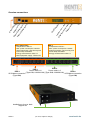
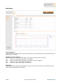
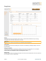
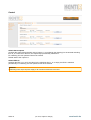
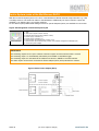
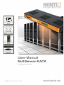
User-Manual
MultiSensor-RACK
From Firmware Version 3.xx.xx
www.kentix.de
Content
1. Introduction an summary!
3
2.
Features!
3
2.1. Applications!
3
2.2. Safety note and installation!
3
2.3. Environment!
3
2.4. Protection!
3
3. Installation!
4
3.1. Default settings !
4
3.2. Recommended installation!
4
3.3. Overview connections !
5
4. Configuration!
6
4.1. Dashboard!
6
4.1.1. MultiSensor!
7
4.1.2. EnergySensor!
8
4.1.3. Control!
10
4.2. Configuration!
11
4.3. Basic Configuration!
11
4.4. MultiSensor!
12
4.5. EnergySensor!
13
4.6. Users!
13
4.7. System !
13
4.8. Software update MultiSensor-RACK!
14
5.
Copy or save Configuration of MultiSensor-RACK!
14
6.
Control a network camera via HTTP requests!
15
6.1. Communication Interfaces!
15
6.2. Kentix-System-jacks at the MultiSensor-RACK!
16
7. Data-sheet MultiSensor-RACK (KMS-RACK)!
17
8. Support!
18
Seite 2! !
!
!
!
(01-2013, subject to change)!
!
!
www.kentix.de
Introduction an summary
Thank you for your decision to buy a KENTIX monitoring solution based on the KENTIX MultiSensor
technology.
Features
The Kentix MultiSensor-RACK is an All-in-One system unit with many integrated sensors.
The MultiSensor-RACK can be a stand-alone device or operated in conjunction with a Kentix AlarmManager.
By the use with an AlarmManager-PRO a more extensive functionality is provided.
The MultiSensor-RACK is installed in a 19“ rack. It controls and forwards all alarm and fault messages to the
responsible persons.
The configuration is done via the integrated web server, comfortable with a web browser.
Applications
•
•
•
•
•
•
Industry and Trade
Banks
Authorities and hospitals
Telecommunications
Law firms and medical practices
Energy and water utility
Safety note and installation
In case of a power failure, the settings are not lost. Energized relays drop out and go back when the power
returns to the unswitched, closed output state.
To bridge longer downtimes, use a suitable UPS system.
In case of an equipment failure an uninterruptible power supply to the connected devices is ensured by the
closed state of the relays.
To ensure the security and integrity of the operator and the correct operation of the KENTIX MultiSensorRACK, the execution of the installation only has to be done by an expert. Also ensure that the relevant
requirements are met.
Environment
Choose an installation place which ensures that the KENTIX MultiSensor-RACK and all associated cables
are not affected by the following environmental conditions: dust, humidity, excessive heat, direct
sunlight, heat sources, devices that build strong electromagnetic fields, liquids or corrosive
chemicals.
See the technical data sheet for more technical data and environment conditions.
Protection
During the installation of the MultiSensor-RACK, certain degrees of protection must be guaranteed. Observe
the relevant regulations for installation in certain environments such as industrial or residential and
commercial buildings.
Seite 3! !
!
!
!
(01-2013, subject to change)!
!
!
www.kentix.de
Installation
The MultiSensor-RACK can be operated as stand alone device, but also in combination with an
AlarmManager-PRO. The AlarmManager then controls the environment sensors.
For configuration in stand alone operation a web server is integrated, which allows you to control and setup
the device via LAN and a web browser.
Over the SNMP interface, an integration in network management systems is possible.
Connection via PC:!
!
!
!
!
!
!
!
!
!
Connect the LAN jack from the MultiSensor-RACK over a LAN cable with your
network and your PC. Pay attention that you have to use a Cross-Over network
cable, by a direct connection.
Set the IP address of your PC to e.g. „192.168.100.123“.
Default settings
Voltage supply:!!
Default IP-address: !
Subnet mask:! !
Gateway:!
!
User:! !
!
Password:!
!
Basic voltage supply realized with PDU-1 power input
192.168.100.223
255.255.255.0
0.0.0.0
admin
password
Important! Resetting the IP address
If you have forgotten the login information of the MultiSensor-RACK, activate the RESET button at the left side of the
device casing (see picture on next page). The device will be reset to the default settings.
Recommended installation
1. If possible, install the MultiSensor-RACK at the top position
in the rack and leave 1 height unit free below the device.
This ensures that the environment sensors can detect the
actual state in the rack.
2. For the installation of the mounting brackets only use the
included screws. The mounting brackets can be attached
to two different positions for installation either to the front or
to the back support rail.
3. Connect the power cable of the power consumers to
PDU 1 or 2 and secure them with the provided strain relief.
Seite 4! !
!
!
!
(01-2013, subject to change)!
!
!
www.kentix.de
sc
ro
l
cro l ba
ck
ll f
o
r
Sy
wa
ste
rd
m
sta
te
Di
sp
la
Di
sp
lay
D
OL
E
ys
nti
xS
Ke
ys
Di
sp
lay
rkP
tem ort
xS
ys -jack
tem
1
-j a
ck
2
tw
o
Ke
nti
Ne
Re
se
t-B
utt
on
Overview connections
PDU-1 (Main PDU)
• Independent of PDU-2
• Max. power consumption 2.300VA
• Internal protection 12A, time lag fuse
• Power Strip switchable
• Energy measurement outlet 1-6
• Main equipment supply - Electronics
PDU-2
• Independent of PDU-1
• Max. power consumption 2.300VA
• Internal protection 12A, time lag fuse
• Power Strip switchable
• Energy measurement outlet 1-6
PDU-2
PDU-1
Power outlet 1-6
Power outlet 1-6
PDU-1
PDU-2
(Type
C13, 2.300VA/10A)
(Type
C13,
2.300VA/10A)
UPS-Mains connection
UPS-Mains connection
(Type C20)
(Type C20)
Installation to front or back
support rail
Seite 5! !
!
!
!
(01-2013, subject to change)!
!
!
www.kentix.de
Configuration
In the following the stand alone functionality of the integrated web servers is described. For these functions
no AlarmManager is required. If you use the MultiSensor-RACK in combination with an AlarmManager-PRO,
configuration and monitoring of the environment sensors is done via the AlarmManager. The energy
measurement and its alarming states are exclusively found in the web interface.
Dashboard
Navigation
Dashboard!
!
!
Login! !
Configuration!
System!!
Help ! !
Logout! !
!
!
!
!
!
!
!
- Start page with environment sensors, Energy measurement,
Control of the digital Output 2 and PDU 1+2
- User login
- Basic configuration, MultiSensor- / EnergySensor- and User-configuration
- System information (software version), test features, logbook and device-restart
- Manual download and support information
- User logout
Seite 6! !
!
!
!
(01-2013, subject to change)!
!
!
www.kentix.de
MultiSensor
Kentix MultiSensor
Shows all actual environment values, the monitoring state of the internal vibration sensor and the state of the
digital Inputs in one table.
MultiSensor values and state:
Display of the sensor values and alarm states. The display is refreshed every 5 seconds.
OK !
- There is no measurement undershot or exceeded
NOK! - There is a measurement undershot or exceeded, an alarm is triggered
ON !
- Function or input / output status is switched on
OFF! - Function or input / output status is switched off
Monitoring
Graphical display of temperature and humidity of the last 7 days. If the memory of the recording is full, the
oldest values will be deleted automatically.
Seite 7! !
!
!
!
(01-2013, subject to change)!
!
!
www.kentix.de
EnergySensor
Energy
Shows all actual energy measurement values for PDU 1+2 (PDU=Power Distribution Unit), the energy
consumption with costs and the alarm state in one table.
IMPORTANT!
To display the costs a price has to be entered in the configuration (section EnergySensor).
Active power
The active power (P) shows the actual power of the PDU. Its calculated by multiplying voltage, current and
the power factor.
Energy consumption
Total energy consumption in kilowatt hours (kWh) since the start of the measurement. The consumption
values are stored in the MultiSensor-RACK and preserved even after a restart.
It can be reset in the configurations menu in the EnergySensor section.
Energy costs
Shows the actual costs for the energy consumption since the start of the measurement. The costs result from
the consumption and the configured price.
Seite 8! !
!
!
!
(01-2013, subject to change)!
!
!
www.kentix.de
Voltage
Display of the actual mains voltage in volt (V).
Current
Display of the actual power demand of the connected power consumers in ampere (A).
Frequency
Actual mains frequency in hertz (Hz).
Apparent power
Total power of the PDU in volt ampere (VA). It results from the idle power and the active power.
Power factor
The power factor is the ratio between active power and apparent power. It indicates which part of the
apparent power is converted to the desired active power.
Monitoring
Graphical display of the recorded active power and energy costs.
The recording is stored for up to 1 year. If the memory of the recording is full, the oldest values will be
deleted automatically.
Seite 9! !
!
!
!
(01-2013, subject to change)!
!
!
www.kentix.de
Control
Switch alarm output 2
Changes the state of the 2nd alarm output (output 1 is controlled by the alarming) for the entered switching
time. If „0“ is entered for the time, the output stays permanently switched on.
For switching, the user password has to be entered.
Default state of the output is 0.
Switch PDU 1/2
Switches the PDU on or off. If the value for the switching time is „0“ or empty, the PDU is switched
permanently. For switching, the user password has to be entered.
WARNING!
Deactivating a PDU stops the power supply to all connected end-devices of the PDU.
Seite 10!
!
!
!
(01-2013, subject to change)!
!
!
www.kentix.de
Configuration
Basic Configuration
Device name / Language
Configuration of the device name. The name can be chosen freely. For an easy identification the use of the
exact place of operation of the MultiSensor-RACK is recommended (e.g.: server-room 3rd floor - rack 1).
Choose between english and german language.
IP-Address / Mask / Gateway
Network configuration of the MultiSensor-RACK.
DNS 1/2
Enter the name-server addresses. Depending on network configuration e.g. on use of an ADSL router it can
be the gateway address.
Public DNS servers: 192.25.2.129 or 194.25.2.130
Time - NTP1/2
Configuration of the time server (network time protocol). The NTP configuration is needed if you use the
time-controlled arming and disarming. If a DNS-Server was entered, it is also possible to use a DNS name
here.
Public NTP servers: 129.69.1.153 / 130.149.17.21 or 0.de.pool.ntp.org
AlarmManager-Communication
Activate the communication with the Kentix AlarmManager here.
Enter the IP-address of the AlarmManager and activate the checkbox.
E-Mail
If the MultiSensor should be able to send e-mails in the case of alarm to a configured user, it is necessary to
set an e-mail server (SMTP or ESMTP). For communication enter the specific network port. If no port is
entered, the MultiSensor uses the default SMTP-port 25. When you have set a DNS server, which is
configured in the DNS settings, you can use the DNS name of the e-mail server here. Using ESMTP you
can enter the e-mail access data, which you can obtain from your e-mail provider. Pay attention that many
mail servers need an existing sender address to send an e-mail correctly.
In the subject of the e-mail the corresponding alarm text can be found and in the mail text all measurements
of the MultiSensor are included.
SNMP
Configuration of the Simple Network Management Protocols. The MultiSensor-RACK is able to send alarm
messages as SNMP-Traps. Furthermore the sensor can be prompted or partially configured via SNMP. The
functions which are available for the SNMP communication are specified in the supplied MIB (Management
Information Base). It is available on the integrated FTP server or as download from the Kentix website.
FTP Server
Switch the integrated FTP-Server on or off. FTP access is needed for software updates of the MultiSensorRACK. See chapter Software update MultiSensor-RACK for this purpose.
Seite 11!
!
!
!
(01-2013, subject to change)!
!
!
www.kentix.de
MultiSensor
In the following settings you can set the limits and trigger values for the alerting of the environment sensors.
When an alarm is triggered, an e-mail will be sent to the configured persons and the internal buzzer is
activated.
Sensor-Temperature, Humidity, Dew-point
Set the alarm limit values. Alarm will be triggered when the measurements undershot or exceed the limits.
The temperature hysteresis is set to 1°C or 1%.
The dew-point will be calculated with the current temperature and the relative humidity from the sensor.
If the room temperature approximates to the difference of the set dew-point hysteresis (2°C default) an alarm
will be triggered. Systems and devices can lead to condensation, when the dew-point temperature
approximates the room temperature. The humidity has reached its saturation.
Sensor-Carbon Monoxide
Alarm settings for the Carbon Monoxide. The sensitivity can be set from 0% to 100% and will be triggered by
exceeding. CO is measured from about 10ppm. There is no exact measurement of the CO content. The
measurement is construed to the highest sensitivity and can be changed slightly in the adjustment.
Carbon Monoxide concentrations like they emerge in fires are detected even at 100% setting.
10%: Minimal concentration of around 10-50ppm lead to an alarm trigger.
100%: Concentrations of 200-400ppm lead to an alarm trigger.
Sensor-Motion
Limit value for the integrated vibration sensor. It is triggered when exceeded.
The sensitivity is adjustable to detect slight shocks (e.g. by moving the rack), but also severe shocks (e.g.
moving the MultiSensor-RACK directly).
Arm-Disarm times
Switching time for the time-controlled arming and disarming from the integrated motion detection.
To use it, a time server (NTP) must be set in the network settings.
Ext. alarm input 1/2
The MultiSensor has two configureable alarm inputs. At this alarm inputs external signaling devices can be
plugged (e.g leakage sensors, door contacts or malfunction messages from external devices). The trigger is
set by a potential free contact (opener). The trigger logic can be set to HI or LOW.
Ext. alarm output
Label for the switching output (output 2). With this output external devices or signals can be switched. It is
controlled via SNMP or the web interface. Pay attention to the electrical connection conditions in the
manuals.
Alarm buzzer time
Time in seconds how long the internal buzzer will sound after an alarm.
Alarm relay time
Time in seconds, how long the open collector output is set when an alarm is triggered. You can trigger with
this output e.g. relays. Pay attention to the electrical connection conditions in the manual.
Re-arming time
Set the time, when the sensor motion detection has to rearm, after a motion alarm is triggered.
The red alarm LED will be turned off after that time.
Alarm repeat
Set the time, when a triggered alarm shall be re-triggered.
The alarm will be sent to the entered e-mail-addresses until all values are in normal range again.
A value of 0 sets the alarm repeating to inactive.
Seite 12!
!
!
!
(01-2013, subject to change)!
!
!
www.kentix.de
EnergySensor
With the following settings set the limits for the alarm triggering of the energy sensors. If an alarm is
triggered, e-mails will be sent to the configured users and the buzzer is activated.
PDU 1/2 - Active power / Voltage / Current
Define a minimum and maximum value for each measured value to monitor the energy measurement.
The minimum values are set to 0 in delivery state. After commissioning and configuration the value range
can be redefined to detect e.g the power failure of an end-device. Find the exact limits for each value in the
data-sheet.
Frequency
Enter a limit as tolerance for an fluctuation of the power frequency.
Reference value is 50 Hz. Adjustment range is 0,1 bis 1,0 Hz (Default value: 0,1 Hz).
Costs
Value for the costs per kilowatt hour and the monetary unit.
Reset energy consumption
Sets the internal consumption counter of the MultiSensor-RACK back to 0 and deletes all recorded data.
For safety reasons the user password has to be entered before the reset.
Users
Enter data for up to 5 users with individual passwords. The passwords also give access to the switching
function of PDU 1+2 and the digital output 2.
The account data of the first user are in addition the account data of the internal ftp-server for running
updates on the MultiSensor-RACK.
For E-Mail alarming enter the addresses of the recipients here.
System
System Information
Shows the firmware version of the MultiSensor-RACK.
Find the actual firmware respectively updates of the firmware on our Kentix Website in the software section.
Test features and Restart
Test the E-Mail and SNMP settings with the two test-buttons. Sending an E-Mail or SNMP-Trap will be stored
in the Logbook.
The MultiSensor-RACK can be restarted for testing or maintenance purposes. Note that the data recording
will stop until the device has restarted.
Seite 13!
!
!
!
(01-2013, subject to change)!
!
!
www.kentix.de
Software update MultiSensor-RACK
The MultiSensor-RACK offers the option to update the software via the integrated FTP server in a simple
way. Latest software updates are available in the download area at www.kentix.de.
The current installed software version can be found on the web server in the section „System“.
Follow this steps to make an update:
No
Step
1
Check that the integrated FTP server is activated. If this is not the case, you can activate the FTP server in
„Configuration“ on the web interface.
2
Extract the corresponding update file (ZIP file) in an extra folder on your PC. The file is named „image.bin“
and must not be renamed.
3
Connect with a FTP client (e.g. Filezilla etc.) to the MultiSensor-RACK. For access use your standard
access data (default: admin/password).
4
Download the files „config.ini“ and „config_e.ini“ to backup your configuration.
5
Transfer the file „image.bin“ to the root directory of the MultiSensor-RACK.
6
After around 1-2 minutes the MultiSensor-RACK will restart automatically. The update file will be deleted
from the filesystem of the MultiSensor. IMPORTANT! During the update procedure the power supply
must not break.
7
Now the MultiSensor is accessible and you can see the software version under „System“ after access.
8
Connect again by using the FTP client and upload your configuration back to the MultiSensor.
Open the Web-Interface and make a restart under „System“ to load your configuration.
Copy or save Configuration of MultiSensor-RACK
No
Step
1
Check that the integrated FTP server is activated. If this is not the case, you can activate the FTP server in
„Configuration“ on the web interface.
2
Connect with a FTP client (e.g. Filezilla etc.) to the MultiSensor-RACK. For access use your standard
access data (default: admin/password).
3
Download the files „config.ini“ and „config_e.ini“ for backup on your PC and close the FTP connection.
4
To transfer the configuration to another MultiSensor, copy the two files to your desired MultiSensor-RACK
and restart the device. Pay attention that this MultiSensor-RACK will then have the same IP-address like the
parents device. You can also change the IP-address in the „config.ini“ using a text editor.
Seite 14!
!
!
!
(01-2013, subject to change)!
!
!
www.kentix.de
Control a network camera via HTTP requests
The MultiSensor-RACK offers the possibility to send a control sequence as a HTTP request to any IP ready
network camera in case of an alarm. So in addition to the e-mail alerting also a video picture or a video
sequence can be sent. The transmission from the video picture is done by the camera.
The information to control the camera has to be inserted into the „cam.ini“ file. Create this file with a text
editor and copy it to the root directory of the MultiSensor via FTP, where you will also find the „config.ini“ file.
After a reboot the configured command sequence will be sent to the camera in case of an alarm. Up to five
cameras can be controlled. Create a new line in the „cam.ini“ file for each camera.
File content (cam.ini)
IP-ADDRESS;IP-PORT;HTTP-CAM-COMMAND;HOST-ADDRESS;SERVER-NAME
The delimiter for each parameter is a semicolon.
EXAMPLE: File content (cam.ini)
192.168.100.224;80;/cam/command/input=trigger;www.kentix.de;My-Camera
The HOST address can be any, is required by some camera servers.
EXAMPLE: File content (cam.ini) for AXIS Video Server 240
192.168.100.224;80;/axis-cgi/io/virtualinput.cgi?action=6:/;www.kentix.de;Axis-Server240
Details for configuring E-Mail events in your network camera and the control sequence can be found
in the manual of the camera manufacturer.
Communication Interfaces
With the MultiSensor-RACK it is possible to send alarms as SNMP Traps.
Additionally all sensor values can be queried using the supplied MIB (Management Information Base).
This allows the integration in network-monitoring-systems like e.g. PRTG or Nagios.
For querying values and also recorded environment- and consumption values the MultiSensor-RACK
furthermore has a XML interface. The following queries can be executed:
XML-Path
Description
http://IP-Address/xml/values.xml
The actual environment values
http://IP-Address/xml/energy.xml
The actual energy measurement values split by PDU 1+2
http://IP-Address/xml/record_values.xml
Recorded environment values of the last 7 days
http://IP-Address/xml/record_energy.xml
Recorded average power per 15 minutes for a timespan of up
to 1 year
NOTE
In contrast to the energy consumption values the environment values are not stored in the MultiSensor-RACK and will
be lost after a reset. After a restart or power loss the recording starts from the beginning.
Seite 15!
!
!
!
(01-2013, subject to change)!
!
!
www.kentix.de
Kentix-System-jacks at the MultiSensor-RACK
With the two Kentix-System-jacks on the front of the MultiSensor-RACK external components like e.g. UPS
or leakage sensors can forward an alarm to the MultiSensor. Additionally two Open Collector outputs are
available, 1 for alarming and 1 for remote switching.
For the alarm inputs prefabricated leakage sensors or special adapters (KIO1) are available for connection.
Figure: PIN assignment of the Kentix System-jack
!
Kentix system jack
1 - GND
2 - Alarm output (Open Collector 100mA)
3 - Remote switch output (Open Collector 100mA)
4 - Power supply 10-32VDC (+/-)
5 - Power supply 10-32VDC (+/-)
6 - External alarm input (External dry contact, no/nc)
7 - External alarm input 2 (External dry contact, no/nc, Default configured as sabotage input)
8 - 5V internal system voltage
IMPORTANT!
The switching outputs 6/7 are open collector transistor outputs and the maximum load is 100mA.
The switching output 1 is automatically switched by an ALARM1 or ALARM 2 trigger.
The switching output 2 is activated via the SMS remote function, SNMP or the web interface.
The alarm inputs can be wired via the Kentix Power Adapter (KIO1) with potential free contacts.
!
!
Seite 16!
Figure: Kentix Power Adapter (KIO1)
!
!
!
(01-2013, subject to change)!
!
!
www.kentix.de
Data-sheet MultiSensor-RACK (KMS-RACK)
Connectable devices
Stand-Alone operation (Integrated Web-Server)
AlarmManager-PRO
Sensor - temperature
range 0 to 99°C
Sensor - Relative humidity
range 0 to 100%
Dew point
calculated in °C
Sensor - motion
Internal vibration sensor, trigger sensitivity configurable
Sensor - carbon monoxide (CO)
Fire detection via CO-Sensor
Internal resolution: 20-200ppm (0-100%) adjustable
Sensor-lifetime: 8 years (replaceable)
Buzzer
85dB, 2.3kHz
KENTIX System jack
2 Kentix System-jacks (SYS 1/2) to connect external Plug´n Play modules
(RJ45) like door contacts , leakage-sensors, external alarms.
Assignment:
2 x Alarm input (ALARM 1, ALARM 2)
2 x Open Collector output 0.1A/12V (1x Alarming, 1x Remote control)
Sensor-Energy measurement
Voltage (V), Current (A), Active Power (W), Apparent power (VAR),
Consumption (kWh), Power factor (%), Consumption total (kWh),
Consumption per month (kWh), Costs (Currency)
Display
OLED Display to display the actual measurement values
LEDs to display ALARMs and RUN
LAN
10/100 Mbit LAN connection (IEEE 802.3)
integrated web-Server
SNMP - Data Interfaces
(Simple Network Management Protocol)
SNMP/V2 (write/read) and SNMP Traps
XML Data-export for measured values
Power supply
100-240VAC, power consumption approx. 4W
Supply of PDU 1+2 with IEC-connector type C20/16A
PDU Connection
(Power Distribution Unit)
2 separate PDU with 6 IEC power outlets (C13/10A) per PDU with strain
reliefs
Maximum power consumption 4.600VA with 2.300VA each for PDU-1 /2
PDU-1 and PDU-2 separately switchable with timer- and reset-function
Measurement accuracy
(at 20°C ambient temperature)
Voltage (RMS 90-260V)!
+/- 0,5%
Current (RMS 0,002-12A)! +/- 0,5%
Active power (1.5-2.760W)! +/- 0,5%
Protection PDU 1/2
2 pcs. 12A micro fuse (5x20mm), time-lag - TH 250V with extinguishant
Casing
IT-Rack 1 HE (44mm), mounting brackets for front and rear
Dimensions: 418 x 165 x 44 mm (B x T x H), weight 1.25kg
Environmental conditions
Temperature 0 - 60°C
Humidity 5-95%, not condensing
Content of delivery
2 pcs. IEC power cable with 3m (Type: C14/C19), 19“ mounting-brackets
Accessories
Leakage sensor (KLS2)
Seite 17!
!
!
!
(01-2013, subject to change)!
!
!
www.kentix.de
Support
For technical questions about the products please contact our support team by e-mail.
Send an e-mail with your questions and all the important details of your application and used versions to our
support address.
KENTIX GmbH
Autenbornstrasse 2
55743 Idar-Oberstein
[email protected]
The manual has been prepared with great care. The correctness and completeness of data, pictures and drawings is not
guaranteed.
Regard to protected brand names and logos:
The use of protected trademarks, trade names, designs and brand logos in this manual is not a copyright violation, but
serves as an illustrative reference. Even if these are not at the appropriate places marked as such, the relevant statutory
provisions. The trade names and logos are the property of the manufacturer and subject to copyright laws. Information
about that, please refer to the instructions of the manufacturers websites.
Copyright Notice:
All rights reserved. Any text, images, graphics, animations and videos as well as content and structure of this manual are
protected by copyright and other laws protecting intellectual property. Your copy, modification, commercial use, use in
other media or transfer to third parties is prohibited or requires the prior express permission of such KENTIX GmbH.
Electronic equipment is not domestic waste - in accordance with directive 2002/96/EC OF THE
EUROPEAN PARLIAMENT AND THE COUNCIL dated 27th January 2003 concerning used electrical
and electronic appliances, it must be disposed of properly. At the end of its service life, take this unit for
disposal at a designated public collection point.
Spent batteries are special waste!
Do not throw spent batteries into your domestic waste; take them to a collection point for spent batteries.
The products complies with applicable European standards and directives and is confirmed by the CE
mark.
The CE conformity declaration is available on request.
Seite 18!
!
!
!
(01-2013, subject to change)!
!
!
www.kentix.de