1
USER’S MANUAL
TRIPLE OUTPUT DC POWER SUPPLY
ARRAY 3631A
ARRAY ELECTRONIC
3631A
User’s manual
ARRAY 3631A
TRIPLE OUTPUT DC POWER SUPPLY
The ARRAY 3631A is a 80W triple output DC power supply. It is easy
to control from the front panel, or with industry standard SCPI
commands via the USB, RS232 or GPIB. The low noise, excellent
regulation, and built-in voltmeter/ammeter make this reliable power
supply the right choice for many applications. It provides quiet, stable
DC power for both manual and automatic testing, in R&D and in
manufacturing environments.
Versatile bench-top features
*
*
*
*
*
*
*
*
0~+6V/0~5A, 0~±25V/0~1A triple output
Highly visible vacuum-fluorescent display
Keyboard and knobs with all functions
Symmetrical tracking operation for ±25V output
Excellent line and load regulation
Low ripple and noise
Up to 10 operating states can be stored for later recall
Portable, ruggedized case with non-skid feet
Flexible system features
* Standardized USB, RS-232 and GPIB(Optional) interfaces
* SCPI(Standard Commands for Programmable Instruments)
compatibility
* Direct setting of I/O Parameters from front-panel
1
3631A
User’s manual
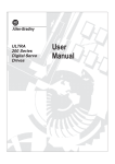
The Front panel at a glance
`
------------------------------------------------------------------------------
1. AC power switch
3. Earth ground terminal
5. Output on/off key
7. Control knob
9. +6V/+25V/-25V output selection key
11. Current setting key
13. Store key
15. Limit value setting/calibrate key
17. Local key
19. Number key
21. Enter key
2
2. +6V supply output terminals
4. ±25V supply output terminals
6. Left/Rright key
8. Display
10. Voltage setting key
12. Tracking enable/disable key
14. Recall key
16. Error key
18. I/O configuration/secure key
20. Clear key
3631A
User’s manual
1.
AC power switch: used to turn the AC power on and off.
2.
+6V supply output terminals: +6V power supply output, the
positive pole is in red, the negative pole is in black.
3.
Earth ground terminal: which is connected to the chassis and
earth ground through a 3-wire ground receptacle.
4.
±25V supply output terminal: ±25V supply output, +25V output
is in red, the common is in black,-25V output is in green.
5.
Output on/off key: turn the power supply on/off.
6.
Left/Right key: Move the blinking digit to left or right, or select
different options.
7.
Control knob: Adjust the value of the blinking digit or select
different options by turning clockwise or counter clockwise.
8.
Display: Show the parameters and status of the power supply.
9.
+6V/+25V/-25V output selection key: Select one power
output to be monitored on front panel.
10.
Voltage setting key (VSET): Dyisplays or modifies the present
voltage setting value.
11.
Current setting key (ISET): Displays or modifies the present
current setting value.
12.
Tracking enable / disable key (Track): Enables /disables the
track mode of ±25V supplies.
13.
Store key (Store): Stores the present operating states in
location “0”, “1”, …… “9.
14.
Recall key (Recall): Recalls a previously stored operating state
from location:
“0”, “1”, “2”, ……“9”.
3
3631A
15.
User’s manual
Limit value setting/calibrate key (Limit/Calibrate): Setting the
maximum of voltage limit value and current limit value; or
enables calibration mode (the power supply must be unsecured
before performing calibration).
16.
Error key (Error): Quries or reads the error codes.
17.
Local key(Local): Returns the power supply to local mode from
remote interface mode.
18.
I/O config/secure key (I/O config): Configures the power supply
for remote interfaces, or secure and unsecure the power supply for
calibration.
.
19.
Number key (0-9 and .): Set the value of the specified function.
20.
Clear key (Clear): Clears present input value or exits current
operation.
21.
Enter key (Enter): Confirms present setting values or option.
4
3631A
User’s manual
Display Annunciators
Adrs
Power supply is addressed to listen or talk over a remote
interface.
Rmt
Power supply is in remote interface controlling mode.
+6V
Displays the output for +6V supply state.
+25V
Displays the output for +25V supply state.
- 25V
Displays the output for -25V supply state.
CAL
Power supply is in calibration mode.
Track
The outputs of +25V and -25V supplies are in track mode.
Set
The power supply is in settings of output voltages and
outputcurrent.
Limit
The display shows the voltage and current upper limit value
of the power supply.
On
The output of power supply is ON.
Off
The output of power supply is OFF.
ERROR
Hardware or remote interface command errors are detected
and also the error bit has not been cleared or read.
Unreg
CV
CC
The output is unregulated (output is neither CV nor CC).
The output of power supply is in constant-voltage mode.
The output of power supply is in constant-current mode.
5
3631A
User’s manual
The rear panel at a glance
-------------------------------------------------------------------------------------------------------------
1. AC inlet
3. AC power-line voltage switch
5. GPIB interface connector(optional)
2. Fuse holder
4. RS-232 interface connector
6. USB interface connector
Use “I/O CONFIG” key on front panel to:
*
*
*
Select the RS-232, USB or GPIB interface.
Select the RS-232 baud rate, parity, number of data bits and
flow control mode.
Set the GPIB bus address.
6
3631A
User’s manual
General Information
Apart from a general description of your power supply, it provides
instructions for checking your power supply, selecting power-line
voltage and connecting to ac power.
Initial Operation
To ensure that the power supply develops its rated outputs and
responds to operation from the front panel properly.
Front-Panel Operation
To describe the use of front-panel keys and knobs in detail and
how to use them to operate the power supply from the front panel.
And also shows how to configure the power supply for the remote
interface and introduce the calibration features in brief.
Remote Interface Reference
The reference information contained could help you program the
power supply over the remote interface, and also introduces how
to program for status reporting.
Application Programs
It provides some remote interface applications to help you develop
programs for your application.
Tutorial
It describes basic operation of linear power supplies and gives
specific details on the related operation and use of the ARRAY
3631A power supplies.
Specifications
It lists the power supply’s each basic specifications.
7
3631A
User’s manual
ntents
Chapter 1
General Information……………………………..………..…..… 12
Safety Considerations……………………………………………..…….….
Description…………………………………………………….……...……….
Installations…………………………………………………….……...………
Initial Inspections………………………………………….…….……….….
Chapter 2
Initial Operations……………….………..………….....…….… 16
Preliminary checkout……………………..…………….………….……….
Power line cord………………………………………………….……….
Power-line voltage selection………………………………….……..….
Power-on checkout……………………………………..………………..….
Output checkout…………………………………………………..………....
Voltage output checkout………………………………………….…..…
Current output checkout……………………………………………...…
Chapter 3
12
12
14
14
17
17
17
20
21
22
23
Front panel operations………………...…..………....……....… 26
Set limit value of voltage/current………………………………….…..…… 29
Constant voltage output setting…………………………………………..…..31
Constant current output Setting……………………………………..…..… 33
Adjusting output voltage…………………………………..……………...……36
Adjusting output current…………………………………….……………… 37
Seting ±25V tracking mode……………………………..…………..…..…. 39
Storeing and recalling operating state……………………………………. 40
Enabling/Disabling the outputs………………………………………….… 43
System-Related operations ..……………………………………….….…. 44
Self-test……………………………………………………….………….. 44
Error information…………………………………………….…….….… 45
Display controlling ……………………………………………………… 46
SCPI language version query……………………………………… 47
Firmware version query………………………………………………... 48
Remote interface configuration………………………………………….... 48
RS-232 interface configuration………………………………………….…. 49
RS-232 interface configuration overview……………………………... 49
RS-232 data frame format…………………………………………..… 50
Connection to a computer or a terminal……………………….….…. 50
DTR/DSR handshake protocol……………………………..…….…... 51
8
3631A
User’s manual
Baud rate selection………………………………………………...……
Parity selection…..............................................................................
Flow control selection………………………………………..…….....…
To set the Baud rate and parity ………………………………….....…
RS-232 troubleshooting……………………………………….........….
Set USB interface……………………………………………………….…..
Set GPIB interface……………………………………………….…………
The power supply calibration……………………………………..…….…..
Calibration password ……………………………………………….………
To unsecure for Calibration…………………………….…………….….…
Calibration……………………………………..…………….…..………..….
Calibration security……………………………………………..….……….
Change the security Code……..………………….…………………..…...
Restore the default calibration parameters …………………………..…..
Initialize/Initiate calibration parameters…………………….……..…...…
Chapter 4
52
53
53
54
55
56
57
59
60
60
65
71
72
73
74
Remote interface references…………………….…………… 77
SCPI command summary……………………………………...………….. 78
An Introduction to the SCPI Language…………………………………… 79
Simplified programming overview……………………………….…….….. 87
Using APPLY command…………………………………………......… 87
Using low-level commands…………………………………….…….… 88
Selecting a trigger source…………………………………….……...… 89
Programming ranges and output identifiers……………….…………. 89
Using APPLY command…………………………………...…….…….…... 90
Output setting and operation commands……………………….………… 91
Output selection commands……………………………………...….... 92
Measurement commands…………………………………………….... 94
Output on/off and tracking operation commands…………………… 95
Output setting commands…………………………………..…….….… 95
Trigger source Choice…………………………………………..…….…… 99
Selection a trigger source ……………………………………..…….… 99
Triggering commands………………………………………….…….… 100
System related commands……………………………….……………...… 101
Calibration commands………………………………….………………...... 104
RS-232 interface commands…………………………….….….………… 106
SCPI status register……………………………………………………….. 107
What is an event register?................................................................ 107
What is an enable register?.............................................................. 107
What is a multiple logical output?..................................................... 108
Status reporting commands……………………………………..……....… 109
9
3631A
User’s manual
SCPI conformance information………………………….…..….………… 117
SCPI confirmed commands…………………………………………... 118
Device Specific Commands…………………………………..….….. 119
Chapter 5
Application programs……………………………….………… 122
Chapter 6
Tutorial…………………………………………………..……… 125
Overview of ARRAY 3631A operation……………………………..…….
Output characteristics……………………………..………...….……..
Unregulated state……………………………………………….……
Unwanted signals…………………………………………..…….……
Connecting the load…………………………………………….……….…
Output isolation…………………………………………………………
Multiple loads…………………………………………………………...
Considerations……………………………………………….………….…
Extending the output……………………………………………….………
Reliability ……………………………………………………………....….
.
Chapter 7
Technical specifications…………………………..…………
125
126
128
128
128
128
129
130
131
132
134
Performance Specifications………………………………………….…… 134
Supplemental characteristics…………………………………………….. 136
APPENDIX
Error Messages………………………………………………. 140
Execution errors…………………………………………………………… 141
Self-test errors…………………………………………………………...… 145
Calibration errors………………………………………………..………… 145
10
3631A
User’s manual
1
--------
General information
11
3631A
User’s manual
General information
This chapter provides a general description of your power supply.
And it also contains instructions related to initial inspection,
selecting the power-line voltage, and connecting your power supply
to AC power.
Safe considerations
This power supply is a Safty Class I instrument provided with a
protective earth terminal. The terminal must be connected to earth
ground through a power source with a 3-wire ground receptacle
when being connected to AC power supply.
Before installation or operation, please check the power supply and
read safety markings and instructions introduced in this manual first.
Please see relevant chapters to see related specific information
about safety operations.
Description
The ARRAY 3631A is a programmable linear regulated DC power
supply. The excellent line and load regulation, extremely low ripple
and noise make it well suited as a high preference power system.
The triple power supply delivers 0 to ± 25 V outputs rated at 0 to 1
A and isolated 0 to +6 V output rated at 0 to 5 A. The ±25V power
supplies also provide tracking mode to supply operational amplifier
and power-amplifying circuit which require symmetrically balanced
voltage. Tracking precision is ±(0.2% output +20 mV). The ±25V
power supplies can also be used in series as a single 0~50V/1A
power supply.
Each output voltage or current can be adjusted independently from
front panel, or controlled over RS-232, USB, or GPIB interface.
Buttons and knobs on the front panel can be used to adjust voltage
and current selected; enable or disable tracking mode of ±25V
output; store or transfer 10 sets of working status of power supply
used frequently, enable or disable the output of triple power supply;
calibrate again without opening out the case when the precision
falls down (including change password for calibration); switch the
power supply from remote
12
3631A
User’s manual
controlling mode to local mode; set and monitor the power supply
over remote interface; monitor the setting and output of power
supply via vacuum-fluorescent display, and all the status indication,
error information appeared during working.
When being controlled over remote interface, it can be used both
as a listener and a speaker at the same time. The power supply
can be set and data can be returned over RS-232, USB, or GPIB
interface by external controller. The following functions can be
performed through RS-232, USB, or GPIB interface:
*
*
*
*
*
*
*
*
Voltage and current programming
Voltage and current readback
Enable or disable track mode
Store/recall working status
Programming syntax error detection
Calibration
Output ON/OFF
System self-test
This power supply is equipped with a vacuum-fluorescent display
for displaying the output of voltage and current. A 4-digit voltage
and a 4-digit current could show the actual or setting value of a
selected supply simultaneously. At any time, the three output
selection keys can switch the displayed value to the output voltage
and current of any one supply to be monitered.
binding terminals on the front panel. The +25V and -25V supply's
outputs share a common output terminal which is isolated from
chassis ground.
The positive and negative terminals of each output can be
grounded, or kept a certain voltage with the chassis ground. But
voltage between each output and the chassis ground should be
kept within ±240 Vdc. The power supply is provided with a
detachable, 3-wire grounding type power cord. The AC line fuse is
on the rear panel. It can be extracted for replacement when
needed.
The power supply can be calibrated from the front panel directly or
with a controller over the GPIB or RS-232 interface without
opening the cabinet. Correction factors are stored in non-volatile
memory. You can guard against unauthorized calibration by using
the “Standard” calibration protection function.
13
3631A
User’s manual
Installation
Initial inspection
When you receive your power supply, please check it for any
obvious damage that may have occurred during shipment or
resulted from other reasons. If any damage is found, contact
the carrier and the Sales Office immediately in order to deal
with it in time.
Keep the original packing materials in case the power supply
has to be returned to Array for repairing in the future. If you
return the power supply for service, please attach a tag
identifying the owner and model number. A brief description of
the malfuction also needs to be included.
Mechanical Check
This check confirms that there are no broken keys or knob,
and that the cabinet and panel surfaces are free from dents
and scratches, and that the display is not scratched or cracked
as well.
Electrical Check
Please see Chapter 2 for an initial operation procedure. When
successfully completed, it can be convinced that the power
supply is operating in accordance with its specifications.
Temperature control
The power supply’s performance will mot be affected when
operating within the temperature range of 0 °C to 40 °C, and
output current may fall down from 40 °C to 55 °C. A DC
brushless fan is used to cool the power supply by drawing cool
air through the rear panel and exhausting it with heat out the
sides.
Sufficient space must be left at the rear and two sides of the
cabinet for air circulation when installing the power supply.
Please remove the rubber bumpers for rack mounting.
Rack mounting
The power supply could be installed in standard 19 inch rack.
Please remove the rubber bumpers at the front and end of
power supply before installing.
14
3631A
User’s manual
2
--------
15
Initial operation
3631A
User’s manual
Initial operation
This chapter mainly focuses on three basic tests before using
the power supply: the preliminary checkout, the power-on
checkout, and the output checkout. The preliminary checkout
is to check the power supply could run correctly. The power-on
test includes a self-test that checks the internal
microprocessors and allows the user visually to check the
display at the front panel under the condition of applying power
to the supply properly. The output check ensures that the
power supply develops its rated outputs and properly responds
to operation from the front panel.
--------------------------------------------------------------------------------------
* In order to make sure whether the power supply is
in accordance with what is required and have better
command of power supply features for later use,it is
suggested that both the experienced and the
inexperienced users should read this chapter prior to
operation
---------------------------------------------------------------------------------------
16
3631A
User’s manual
Preliminary Checkout
ARRAY 3631A power supply can be used from a nominal 115
V or 230 V single phase AC power source at 47 to 63 Hz. There
is an indication below the AC power inlet on the rear panel
showing the nominal input voltage set for the power supply at
the factory.
Power line cord
The power supply is shipped from the factory with a power-line
cord that has a plug appropriate for your location. Please
contact the nearest ARRAY Sales and Service Office if the
wrong power-line cord is included with your power supply. Your
power supply is equipped with a 3-wire grounding type power
cord; the third conductor being the ground. The power supply is
grounded only when the power-line cord is plugged into an
appropriate receptacle. Do not operate your power supply
without adequate cabinet ground connection.
Power-Line Voltage Selection
Usually power-line voltage has been set at the factory. Please
check the indication on the rear panel before using to make
sure the input voltage. Power-line voltage selection is
accomplished by adjusting two components if modification
needed: AC power-line voltage selector and power-line fuse.
To change the power-line voltage, proceed as follows:
2. The modification of AC power-line voltage selector is
shownas follows:
17
3631A
User’s manual
As the figure shows, you can choose distinct input voltage by
moving the selection switch to left or right to accord with the
location standard voltage.
2. Replace the fuse:
Step 1. Remove the fuse-holder with a flat-blade screwdriver
from the rear panel.
Step 2. Replace the fuse with the correct one that meets the
requirements.
Step 3.
Put back the fuse holder.
18
3631A
User’s manual
For 115Vac operation, 2.5AT fuse must be used;
For 230Vac operation, 2.0AT fuse must be used.
Specific checks could be accomplished by following 3 steps:
1. Verify the AC power supply voltage setting
The AC power supply voltage is set to the proper value for your
country when the power supply is shipped from the factory.
However, it is still needed to make sure whether the voltage
value on the rear panel accords with the voltage default.
Change the voltage setting if it is not correct. The settings are:
115, or 230 V.
2. Verify that the power-line fuse is installed correctly.
The correct fuse is installed for your country when the power
supply is shipped from the factory. But checks are still needed
to verify the fuse on the rear panel is installed and the
specification is appropriate for the power supply.
For 115 Vac operation, you must use a 2.5 AT fuse.
For 230 Vac operation, you must use a 2.0 AT fuse.
3. Connect the power-line cord and turn on your powersupply.
A power-on self-test occurs automatically when you turn on the
power supply. And the front-panel display will show the self-test
procedure. Self-test costs about 2seconds.
19
3631A
User’s manual
Power-On Checkout
The power-on test includes an automatic self-test that checks
the internal microprocessors and system self-test after the
power supply is turned on and information related to self-test
procedure shown on display. You will observe the following
sequence on the display:
2. Self-test started
It begins to initial operation immediately after pressing the
power switch on. Then self-test starts. The self-testing
involves internal microprocessor and whole power supply
system. The display shows as following:
2. Self-test accomplished:
If there is no error or abnormity has been detected during
self-testing, the display shows as following
3. Waiting for output:
When self-test accomplished, the power supply is in
power-on or reset status. All outputs are disabled, and the
output selection is +6V. The display shows as following:
20
3631A
User’s manual
In the above figure, “OFF” shows that all outputs are disabled,
and“+6V” shows that +6V power supply output is being
monitored.
4.
Enable the output
Press “OUT on/off” to enable the output. The “OFF”
annunciator on display turns off, and the “+6V”, “ON”, “CV”
annunciators turn on. At this time the display switches to
monitoring mode automatically to monitor the actual value of
voltage and current output
------------------------------------------------------------------------------------------
* If power-on self-test has detected any error or
abnormity, the “ERROR”annunciator is lit. For specific
information about errors please see related chapters in
appendix.
Output checkout
The output checkout is to ensure that the power supply
develops its rated outputs and properly responds to each
operation. Specific steps are shown as followings:
21
3631A
User’s manual
Voltage Output Checkout
1. Turn on the power supply.
Press the “power-on” button, and finish the power-on checkout.
Usually the power supply will go into the power-on / reset state
automatically. All outputs are disabled (the “OFF” annunciator
turns on); the display is selected for monitoring the +6V supply
(the +6V annunciator turns on).
2. Enable the outputs
Press the “OUT on/off” to turn on the power supply output. Now
the display is in monitoring mode and the CV, ON and +6V
annunciators are lit. At the same time a 4-digit voltage meter
and a 4-digit current meter are displayed. Each of them shows
the actual value of output voltage and current of +6V power
supply, respectively.
3. Check if the voltmeter properly responds to knob control on
front panel for the +6V supply
Knob checkout
When the power supply output is on and the display is in
monitoring mode, move the blinking digit to voltage value
displayed by pressing the key “LEFT”. Turn the knob clockwise
or counter clockwise to check that the voltmeter responds to
knob control to increase or decrease and the ammeter
indicates nearly zero.
Key checkout
When the power supply output is on and the display is in
monitoring mode, press key “VSET”, the SET annunciator turns
on, and the voltage setting value is blinking. Press the number
keys on front panel directly to set voltage value needed. Then
press ENTER to verify and finish setting and go back to
monitoring mode. This process is to check that the voltage
value displayed responds the key operation correctly.
4. Check if the voltage can be adjusted from zero to the
maximum rated value.
Adjust the knob until the voltmeter indicates 0 volts and then
adjust the knob gradually until the voltmeter indicates 6.0 volts
22
3631A
User’s manual
and at the same time check the voltmeter and output voltage
changes as it changes.
5. Check the voltage function for the +25V supply.
Adjust selection key for the +25V supply. The CV annunciator
is lit and the +25V annunciator will turn on and +6V turns off.
Repeat steps 3 and 4 to check the voltage function for the +25V
supply.
6. Check the voltage function for the -25V supply.
Adjust selection key for the -25V supply. The CV annunciator is
still lit and the -25V annunciator turns on and +25V annunciator
turns off. Repeat steps 3 and 4 to check the voltage function for
the -25V supply.
Current output checkout
1. Turn on the power supply and finish the power-on checkout.
Usually the power supply will go into the power-on / reset state
automatically; all outputs are disabled (the OFF annunciator
turns on); the display is selected for monitoring the +6V supply
(the +6V annunciator turns on).
2. Connect a short across (+) and (-) output terminals of the
+6V supply with an insulated test lead.
3. Enable the outputs.
Press the OUT on/off button, turn on the +6V supply and the
display is in monitoring mode. The ON and +6V annunciators
are lit. At the same time a 4-digit voltage meter and a 4-digit
current meter are displayed, which show the actual value of
output voltage and current of +6V power supply, respectively.
The CV or CC modes depend on the resistance of the test lead.
4. Adjust the voltage limit value to 1.0 volt.
Adjust the voltage limit to 1.0 volt to assure CC operation.
Please see related chapters about voltage and current setting
in front panel in this manual for specific operations.
5. Check that the front-panel ammeter properly responds to
knob control for the +6V supply.
23
3631A
User’s manual
Knob checkout
When the power supply is on and the display is in monitoring
mode, press key RIGHT to move the blinking digit to current
value displayed; and turn the knob clockwise or counter
clockwise to check if the current value displayed increases or
decreases as it changes.
Key checkout
When the power supply is on and the display is in monitoring
state, press key ISET, the SET annunciator will light on, and
the current setting value is blinking. Press the number keys on
front panel directly to set current value needed. Then press
ENTER to verify and finish setting, go back to monitoring mode.
This process is to check that the current value displayed
responds the key operation correctly.
6. Ensure that the current can be adjusted from zero to the
maximum rated value.Adjust the knob until the ammeter
indicates 0 amps and then until the ammeter indicates 5.0
amps.
7. Check the current function for the +25V supply.
Press OUT on /off, adjust the output selection key for the +25V
supply and connect a short across (+) and (COM) output
terminals of the ±25V supply with an insulated test lead.
Repeat steps from 3 to 6.
8. Check the current function for the -25V supply.
Press OUT on /off, adjust the output selection key for -25V
supply, and connect a short across (-) and (COM) output
terminals of the ±25V supply with an insulated test lead.
Repeat steps 3 through 6.
-----------------------------------------------------------------------------------------------
* If an error has been detected during the output checkout
procedures, the ERROR annunciator will turn on. See the
related chapters in appendix for more specific error
information.
-----------------------------------------------------------------------------------------------
24
3631A
User’s manual
3
--------
Front panel operation
25
3631A
User’s manual
Front panel operation
The installation and initial operation of the power supply are
introduced in the last chapter, and a brief introduction of power
supply usage is included. This chapter will describe in detail the
use of these front-panel keys and show how they are used to
accomplish power supply operation.
• Front-Panel Operation Overview
• Setting of limit value of voltage/current
• Constant Voltage setting
• Constant Current setting
• Tracking Operation setting for ±25V supply
• Storing and Recalling Operating States
• Disabling the Outputs
• System-Related Operations
• USB Interface Configuration
• RS-232 Interface Configuration
• GPIB Interface Configuration
• Calibration Overview
Front-Panel Operation Overview
Please read this chapter before using the power supply:
*
The AC Power On/Off key is used for switching the power
supply on/off. The AC power is on when the key is pressed, and
the AC power is off when the key bounces up.
*
Out On/Off key
The output of the power supply could be switched on or off
through this button. When the output of the power supply is on,
the “ON” annuciator on the front panel is lit; when the output of
the power supply is off, the “OFF” annuciator on the front panel
is lit. It is noticed that no matter which supply is being
26
3631A
User’s manual
monitored, the operation of switching on/off can be used for
triple outputs. At the same time, all states and related
information of present supply will be displayed on the display of
front panel. So that users could have the knowledge of the
working state of the power supply in time. Please see related
chapters in the followings for details.
*
LEFT/RIGHT keys
Used to move the blinking digit on the display, or to switch the
options.
*
Knobs are used to adjust and modify the values. Please see
related chapters in the followings for specific introductions of
related functions.
*
Output selection keys
Used to select the certain supply output which is needed to be
monitored on the front panel.
*
Voltage setting key
Used to set the output voltage of the power supply. No matter
which supply of +6V, +25V, or -25V is selected, just press this
key can enter voltage setting mode to reset voltage value of
present supply. Please see related chapters in the followings
for specific introduction of related operations.
*
Current setting key
Used to set the output current of the power supply. No matter
which supply of +6V, +25V, or -25V is selected, just press this
key can enter current setting mode to reset current value of
present supply. Please see related chapters in the followings
for specific introduction of related operations.
*
Tracking key
Used to enable/ disable voltage tracking function of +25V and
-25V power supply. Please see related chapters in the
followings for specific introduction of related operations.
27
3631A
User’s manual
*
Store key
It is used to store present working state of the power supply
and to simplify the operation of working state transition of
power supply. Related state information of power supply is
stored in non-volatile memory of the micro-controller, which can
be recalled by user at any time. Please see related chapters in
the followings for specific introduction of related operations.
*
Recall key
It is used to recall stored working state and to simplify the
operation of the frequent working state transition of power
supply. The state information recalled is stored in non-volatile
memory of the micro-controller. Please see related chapters in
the followings for specific introduction of related operations.
*
Limit value setting key
Used to set output limit value of the power supply. The limit
value is the maximum of voltage and current which each output
supply is permitted to set. Press “Limit”, the annunciator will
light on. And the limit value of voltage and current of present
output supply will be shown on display. The setting value will
not exceed the limit value. Please see related chapters in the
followings for specific introduction of related operations.
*
Error checkout key
Used to check the error code occurred due to the misuse of
hardware and software or various incorrect operations. So that
users can know about error information in time and then use
the power supply correctly. Please see related chapters in the
followings for specific introduction of related operations.
*
Local key
It is used to switch the power supply from remote mode to local
mode without sending the key-locking command to power
supply by remote interface. Please see related chapters in the
followings for specific introduction of related operations.
28
3631A
User’s manual
*
I/O setting key
Used to set parameters of remote interface. Please see related
chapters in the followings for specific introduction of related
operations.
*
Number keys
Used to enter value needed in the related state.
*
Clear key
In different states, it is used to clear values entered at present,
return to last step or quit present operation. Please see related
chapters in the followings for specific introduction of related
operations.
*
Enter key
It is used to confirm the numbers entered at present or operate
or perform the order selected.
Setting limit value of voltage and current
The limit value of voltage set a maximum of voltage which the
power supply permitted, and the limit value of current set a
maximum of current which the power supply permitted. The
limit value of voltage/current of +6V, +25V, -25V is 6.2V/5.2A,
26V/1.1A, -26A/1.1A.respectively. The users can reset the limit
value of voltage and current if needed in order to restrict
outputs or protect external circuits. There are two methods to
set limit value of voltage and current from front panel:
1. Use Left/Right key, number keys, and Enter to change the
limit value of voltage/current of the power supply.
A. Press “Limit” to enter into limit value setting state. The limit
value of voltage and current are shown on the display. The
voltage limit value is blinking.
29
3631A
User’s manual
B. Use number keys to enter voltage limit value
C. Press Enter to confirm voltage limit value, and then switch
to current limit value setting state.
D. Use number keys to enter current limit value.
E. Press Enter to confirm and the power supply will go back to
waiting state automatically.
If you want to exit halfway, please press “Clear” .
2.
Use Left/Right, knobs and Enter to change voltage/current
limit value.
A. Press “Limit” to enter limit value setting state. The limit value
of voltage and current are shown on the display. The
voltage limit value is blinking.
B. Use Left/Right to select voltage limit value digit which needs
to be modified. The data digit selected is blinking.
C. Increase or decrease the numbers to the needed by turning
the knob clockwise or counter clockwise, then move to the
next digit to modify by pressing Left/Right keys.
D. Press Enter to confirm voltage limit value and then switch to
current limit value setting value.
E. Adjust Left/Right keys and knob for the desired current limit
value as adjusting voltage limit value. Press “Enter” to
confirm. The power supply will go back to waiting state
automatically. If you want to exit halfway, please press
“Clear”.
30
3631A
User’s manual
Constant voltage output setting
Constant voltage output is the most common output of the
power supply. The voltage outputs at a constant value in
constant voltage output mode, and it will not change as the load
changes while the current will. The CV annunciator on the
display of front panel will turn on when the power supply is in
constant current mode. The methods of constant voltage output
are introduced in the following with +6V power supply as an
example (the same as +25V, -25V)
1. Connect a load to the relevant output terminals.
Turn off the power supply. Connect the load to the relevant
output terminals. Set +6V output as an example, connect the
positive pole of the load to “+” terminal of the +6V output, and
connect the negative pole to “-” terminal of the +6V output.
2.
Turn on the power supply
Press the POWER ON/OFF button in the front panel. The
power supply will go into power-on/ reset state after self-testing.
Triple outputs are all off (the OFF annunciator turns on), the
display is selected for monitoring the +6V output (the +6V
annunciator turns on).
To set up the power supply for +25V supply or -25V supply
operation, you should press the +25V or -25V key to select the
display and adjust for +25V supply or -25V supply before
proceeding to the next step.
3.
Set desired output voltage
Desired output voltage can be set directly by pressing number
keys or using LEFT/RIGHT key together with the knob.
A.Using number keys and Enter key to input:
① Press VSET to enter into voltage setting state;
31
3631A
User’s manual
② Input the desired voltage value by pressing number keys,
“Clear” key can be used to clear the wrong value to input
again;
③ Press Enter Key to confirm the voltage setting value.
B. Use LEFT/RIGHT keys, knob and Enter key to input:
① Press VSET to enter into voltage setting state;
② Press LEFT/RIGHT keys to move the blinking digit to the
relevant digit of the value.
③ Increase or decrease the relevant value by turning the
knob clockwise or counter clockwise, then use LEFT/RIGHT
keys to move to the next digit to modify. Clear key can be
pressed to delete the wrong numbers if they are input by
mistake.
④ Press Enter key to confirm the voltage setting value.
4. Set the maximum current
The maximum current can be set directly by pressing the
number keys or using LEFT/RIGHT keys together with the
knob.
A. Using number keys and Enter key to input:
① Press ISET to enter current setting state;
② Input the desired current value by pressing number keys,
“Clear” key can be used to clear the wrong value to input
again;
③ Press Enter Key to confirm the current setting value.
32
3631A
User’s manual
B. Use LEFT/RIGHT keys, knob and Enter key to input:
① Press ISET to enter current setting state;
② Press LEFT/RIGHT keys to move the blinking digit to the
relevant digit of the value.
③ Increase or decrease the relevant value by turning the
knob clockwise or counterclockwise, then use LEFT/RIGHT
keys to move to the next digit to modify. Clear key can be
pressed to delete the wrong numbers if they are input by
mistake.
Press Enter key to confirm the current setting value.
5. Enable the outputs.
Press the OUT on/off key to enable the outputs. The “OFF”
annunciator turns off and the ON and CV annunciators are lit.
Verify that the power supply is in the constant voltage mode.
If you operate the power supply in the constant voltage (CV)
mode, verify that +6V, ON and CV annunciators are lit. If you
operate the power supply for the +25V supply or the -25V
supply, the +25V or -25V annunciator will turn on. If the CC
annunciator is lit while the CV annunciator turns off, which
indicates that the actual output current value has reached our
setting value, please choose a higher current limit.
-----------------------------------------------------------------------------------------------
* During actual CV operation, if a load change causes the
current limit to be exceeded, the power supply will
automatically crossover to the constant current mode at the
preset current limit and the output voltage will drop
proportionately.
When setting voltage or current, the voltage or current will
be set as limit value if the value input on the keyboard is
larger than the limit value.
-----------------------------------------------------------------------------------------------
33
3631A
User’s manual
Constant current output setting
When the power supply is in constant current mode, the current
will output at a constant value, and it will not change as the load
changes while the voltage will. The CC annunciator on the
display of front panel will turn on when the power supply is in
constant current mode.
The methods of constant current output are introduced in the
following with +6V power supply as an example (the same as
+25V, -25V).
1. Connect a load to the relevant output terminals.
Turn off the power supply. Connect the load to the relevant
terminals. Set +6V output as an example, connect the positive
pole of the load to “+” terminal of the +6V output, and connect
the negative pole to “-” terminal of the +6V output.
2. Turn on the power supply
Press the POWER ON/OFF button in the front panel. The
power supply will go into power-on/ reset state after self-testing.
Triple outputs are all off (the OFF annunciator turns on), the
display is selected for monitoring the +6V output (the +6V
annunciator turns on).
To set up the power supply for +25V supply or -25V supply
operation, you should press the +25V or -25V key to select the
display and adjust for +25V supply or -25V supply before
proceeding to the next step.
3. Maximum output voltage setting
Desired output voltage can be set directly by pressing number
keys or using LEFT/RIGHT key together with the knob.
A. Using number keys and Enter key to input:
① Press VSET to enter voltage setting state;
② Input the desired voltage value by pressing number
keys, “Clear” key can be used to clear the wrong value to
input again;
34
3631A
User’s manual
③ Press Enter Key to confirm the voltage setting value.
B. Use LEFT/RIGHT keys, knob and Enter key to input:
① Press VSET to enter voltage setting state;
② Press LEFT/RIGHT keys to move the blinking digit to
the corresponding digit of the value.
③ Increase or decrease the relevant value by turning the
knob clockwise or counter clockwise, then use
LEFT/RIGHT keys to move to the next digit to modify.
Clear key can be pressed to delete the wrong numbers if
they are input by mistake.
④ Press Enter key to confirm the voltage setting value.
4. Set the desired current
The desired current can be set directly by pressing the number
keys or using LEFT/RIGHT keys together with the knob.
A. Using number keys and Enter key to input:
① Press ISET to enter into current setting state;
② Input the desired current value by pressing number
keys, “Clear” key can be used to clear the wrong value to
input again;
③ Press Enter Key to confirm the current setting value.
B. Use LEFT/RIGHT keys, knob and Enter key to input:
① Press ISET to enter into current setting state;
② Press LEFT/RIGHT keys to move the blinking digit to
the corresponding digit of the value.
35
3631A
User’s manual
③ Increase or decrease the relevant value by turning the
knob clockwise or counter clockwise, then use
LEFT/RIGHT keys to move to the next digit to modify.
Clear key can be pressed to delete the wrong numbers if
they are input by mistake.
④ Press Enter key to confirm the current setting value.
5. Enable the outputs
Press the OUT on/off key to enable the outputs. The OFF
annunciator turns off and the ON and CC annunciators are lit.
6. Verify that the power supply is in the constant current
mode.
If you operate the power supply in the constant current mode,
verify that +6V, ON and CV annunciators are lit. If you operate
the power supply for the +25V supply or the -25V supply, the
+25V or -25V annunciator will turn on. If the CV annunciator is
lit while the CC annunciator turns off, please reset a higher
current limit.
-----------------------------------------------------------------------------------------------
* During actual CC operation, if a load change causes the
output voltage exceeds the previous voltage setting value,
the power supply will automatically crossover to the
constant voltage mode according to the previous voltage
setting value, and the output current will drop
proportionately.
* When setting voltage or current, the voltage or current
will be set as limit value if the value input on the keyboard
is larger than the limit value.
-----------------------------------------------------------------------------------------------
36
3631A
User’s manual
Adjusting output voltage
There are two methods of adjusting the output voltage when
the outputs are enabled.
Method 1:
1. Press VSET key first as mentioned before;
2. Input the voltage value again by pressing the keys on the
keyboard or turning the knob
3. Press “Enter” key to confirm at last
Method 2:
1. Press RIGHT key when actual voltage and current are
shown on the display, then the last digit of the voltage value
begins to blink;
2.
Use LEFT/RIGHT keys to move the blinking digit;
3.
Then turn the knob to adjust the value of the blinking digit;
4. Press RIGHT key to modify the next digit until all digits are
not blinking; or wait for several seconds until the display exit the
blinking state automatically.
---------------------------------------------------------------------------------------------
* Both of the above two methods can be used to adjust
the output voltage, but notice that VSET key is used to
adjust the output voltage in the first method, while actual
output voltage does not change until the Enter key is
pressed. In the second method, the output voltage has
been changed while modifying the value of blinking digit
through turning the knob without pressing the Enter key.
---------------------------------------------------------------------------------------------
37
3631A
User’s manual
Adjusting output current
There are two methods of adjusting the output current when the
outputs are enabled.
Method 1:
1. Press ISET key first as mentioned before;
2. Input the current value by pressing the keys on the
keyboard or turning the knob again
3. Press Enter key to confirm at last
Method 2:
1. Press LEFT key when actual voltage and current are
shown on the display, then the last digit of the voltage value
begins to blink;
2. Use LEFT/RIGHT keys to move the blinking digit;
3. Then turn the knob to adjust the value of the blinking digit;
4. After adjustment, press RIGHT key until all digits are not
blinking; or wait for several seconds until the display exit the
blinking state automatically.
---------------------------------------------------------------------------------------------
* Both of the above two methods can be used to adjust
the output current ,but it is need to notice that ISET key
is used to adjust the output current in the first method,
while actual output current does not change until the
Enter key is pressed. In the second method, the output
voltage has been changed while modifying the value of
blinking digit through turning the knob without pressing
the Enter key.
---------------------------------------------------------------------------------------------
38
3631A
User’s manual
Setting ±25V tracking operation
+25V and -25V supplies outputs are provided with voltage
positive and negative inputs tracking function. In the track
mode, the ±25V supplies provide 0 to ±25 V tracking outputs,
two voltages of the ±25V supplies track each other within
±(0.2% output +20mV). When track mode is enabled, any
change of the voltage in either the +25V supply or the -25V
supply will cause the change in other supply.This function can
provide steady symmetrical voltages needed by circuits using
balanced positive and negative inputs. The track mode is
always in off state when power has been off or after a remote
interface reset.
To operate the power supply in the track mode, proceed as
follows:
1.Switch to +25V or -25V supply output
Adjust the power supply to CV mode of +25V or -25V supply as
mentioned before. “ON”, “CV”, and “+25V”or “-25V”
annunciators are lit.
2. Enable the track mode
Press “Track” key and hold on for over 2 seconds to enable the
track mode. Then the “Track” annunciator on the display turns
on. And a short beep will be generated. When the track mode is
first enabled, the -25V supply will be set to the same voltage
level as the +25V supply. After the completion of setting, the
two voltages of the ±25V supplies track each other and any
change of the voltage in either the +25V supply or the -25V
supply will cause the change in other supply.
3. Verify that the power supply is in the track mode.
Compare the voltage values of the ±25 supplies, and ensure
the amplitudes of the output voltages of both supplies are the
same, while the electrodes are opposite.
39
3631A
User’s manual
If you want to disable the track mode, just press “Track”key
again, and the “Track” annunciator turns off.simultaneously.
---------------------------------------------------------------------------------------------
* In the track mode of ±25V supplies, if the CV
annunciator turns off and the CC annunciator is lit in any
supply of both ones, please choose a higher current limit
for this supply, or the voltage will be unable to track.
-----------------------------------------------------------------------------------------------
Storing and Recalling Operating States
ARRAY 3631A power supply can store 10 sets of operating
states from 0 to 9. The users can just operate on the front panel
simply to store common setting, which saves you a lot of time
for adjusting the outputs and setting the working state of the
power supply frequently, and simplifies operating procedures.
The states of the power supply after being turned on are as
follows: all outputs are disabled, the track mode is off; the limit
value of +6V, +25V and -25V voltage/current are 6.2V/5.2A,
26V/1.1A; -26V/1.1A, respectively; the setting value of
voltage/current are 0V/5A, 0V/1A, 0V/1A; the keys and knob
and the display on the front panel are used to control and
monitor the output of +6V supply.
The following steps are showing how to store and operate an
operating state:
1. Set up the power supply for the desired operating state.
Set up the power supply for the desired state, which including:
outputs enabled/disabled; track mode setting; voltage/current
limit value output by each supply, voltage/ current setting value;
keys, knob, the output object monitored by the display.
40
3631A
User’s manual
2. Store the operating state
10 states can be stored in the inner memory of 3631A,
numbered from ‘0’ to ‘9’ without any preference in location. The
contents stored in the memory will be covered when storing
again.
A. Press Store key to enable the storage mode. The display
of the front panel shows as follows:
B. The blinking number shows the memory location, 10 sets
of states can be stored in all from 0…9. The memory
location could be chosen through number keys and knob.
C. Press Enter key to confirm, the following will appear on
the display after the storing is done:
D.To cancel the storing operation, press “Store” key again
or press “Clear” or just wait for several seconds without
any operation, then the power supply will exit the storage
mode automatically.
--------------------------------------------------------------------------------------------
* The output of the power supply will not be affected
when the storing operation is on.
--------------------------------------------------------------------------------------------
41
3631A
User’s manual
3. Recalling operation
A. Press “Recall” key to enter recalling state, the display
shows as follows:
B. The blinking number shows recalling location, which are
numbered from 0-9 and can be chosen by the number keys
and the knob.
C. Press Enter key to perform recalling. The states below
will change as the recalling contents changes, which
including: outputs enabled/disabled; track mode setting;
voltage/current limit value output in each supply, voltage/
current setting value; keys, knob, the output object
monitored by the display.
To cancel the recalling operation, press “Recall” key again
or press “Clear” key or just wait for several seconds without
any operation, then the power supply will exit the recalling
mode automatically.
-----------------------------------------------------------------------------------------------
* The output of the power supply will change when the
recalling operation is on.
-----------------------------------------------------------------------------------------------
42
3631A
User’s manual
Enabling/Disabling the outputs
“OUT on/off” key can be used to turn on/off the output of the
power supply.
When the power supply is turned off, “OUT on/off” key can be
used to turn on the outputs. Press this key again to turn off the
outputs again.
When the outputs of the power supply is off, “OUTPUT OFF”
will appear on the display and the OFF annunciator will turn on.
The keys and the knob still can be used. When the outputs are
on, the actual value of voltage and current will appear on the
display and the ON annunciator is on. If you want to see the
setting value, press VSET or ISET to make the display in the
voltage or the current setting mode.
When the power supply is off or after the reset of a remote
interface, all the outputs are enabled.
When operating at a remote interface, enter the command as
follow to enable or disable the outputs:
OUTPUT ON/OFF
The outputs are enabled when the “ON” parameter is selected
and disabled when the “OFF” parameter is selected.
43
3631A
User’s manual
System-Related Operations
This section gives information on topics such as self-test, error
information, and front-panel display control, SCPI version
check, firmware version query. This information is not directly
related to setting up the power supply but is an important part
of operating the power supply.
Self-test
Self-test has been mentioned briefly in chapters before, and on
which more detailed information is introduced here. A power-on
self-test occurs automatically when you turn on the power
supply. This test assures you that the power supply is
operational if the self-test pass and no error occurs.
when the power-on self-test starts, the display shows as
follows :
1.
The self-test is on
2.
Self-test passed
3.
Enabling/Reset state
44
3631A
User’s manual
If the error occurs during the self-test or the self-test fails,
please contact with the distributor, or send it back to us. If error
occurs, “PASS” will not be displayed on the display of the
power supply. And the “ERROR” annunciator will turn on with a
short beep after return to the enabling/reset state. As the
following figure shows:
The command can also be sent through remote interface to
perform self-test operation:
*TST?
Returns “0” if the complete self-test passes or “1” if it fails.
Error information
When the “ERROR” annunciator turns on, it indicates that at
least an error is detected, which may be the remote interface
command syntax or the hardware error. A record of up to 20
errors can be stored in the power supply's error queue. See
“Error Messages” in the index of manual for a complete list of
the error information.
1. Errors are retrieved in first-in-first-out (FIFO) order. The first
error returned is the first error that was stored. When you
have read all errors from the queue, the ERROR
annunciator turns off.
2. If more than 20 errors have occurred when you operate the
power supply over the remote interface, the last error stored
in the queue (the most recent error) is replaced with “-350,
“Too many errors””. No additional errors are stored until you
have read errors or removed errors from the queue, which
means that only 19 errors are able to see when operate
the power supply over the remote interface,and the 20th
error is replaced with “-350, “Too many errors””.
3. If all errors are read or no errors have occurred, which
shows no error is stored in the queue, the power supply
responds with “0, “No error”” over the remote interface.
45
3631A
User’s manual
4. The error queue is cleared completely after a *CLS (clear
status) command has been executed over the remote
interface.
5. Front-panel operation:
If the ERROR annunciator is on, press the key repeatedly to
read the errors stored in the queue. The “ERROR”
annunciator turns off when you read all errors.
6. Remote interface operation:
SYSTEM:ERRor?
Reads one error from the error queue
Display control
For security reasons, you can turn off the front-panel display,
and display a 12-character message on the front panel. This
function can be performed from the remote interface only.
1. When the display is turned off, outputs are not sent to the
display and all annunciators are disabled except the
ERROR annunciator and “Rmt” annunciator. Front-panel
and knob operation is unaffected by turning off the display.
2. When the power is restarted, the display is always enabled
after a remote interface reset, or after returning to local from
remote.
3. You can display a message on the front panel by sending a
command from the remote interface. The power supply can
display English letters, Arabic numerals and spaces up to
12 characters of the message on the front panel; any
additional characters are truncated. All the appeared
special marks are displayed in the form of the blank spaces
with individual display space respectively.
4. Sending a message to the display from the remote interface
overrides the display state; this means that you can display
a message even if the display is turned off.
46
3631A
User’s manual
5. The display state is automatically turned on when you
return to the local (front panel) operation. Press the “Local”
key to return to the local state from the remote interface
6. Remote interface operation commands:
DISPLAY ON/OFF
(Disable / enable the display)
DISPlAY: TEXT <single quoted string>
(Display the string enclosed in single quotes)
DISPlAY:TEXT:CLEAR
(Clear the displayed message and exit the display state)
For example, If you want to display “all123456789” charater
string, send following message to the display:
DISPLAY:TEXT ‘all123456789’
SCPI Language Version
The power supply complies with the rules and regulations of
the present version of SCPI (Standard Commands for
Programmable Instruments). You can query the SCPI version
with which the power supply is in compliance by sending a
command from the remote interface.
Remote interface operation command:
SYSTEM:VERSion?
Returns a string in the form “YYYY.V” where the “Y’s” represent
the year of the version, and the “V” represents a version
number for that year (for example, 1995.0).
Notes:
You can query the SCPI version from the remote interface only.
47
3631A
User’s manual
Firmware Revision Query
The power supply has microprocessors for control of various
internal systems. You can query the power supply to determine
which revision of firmware is installed for each microprocessor.
You can query the firmware revision from the remote interface
only.
Use commands below to check the firmware revision No.
through remote interface:
*IDN?
Returned value:
ARRAY,3631A,0,1.3-1.0-1.5
The value returned is separated by commas and consisted of 4
fields. The first field represents the manufacturer, the second
represents the model of the product, the third reserved, and the
fourth field is a revision code which contains three numbers.
The first number is the firmware revision number for the main
processor; the second is for the input/output processor; and the
third is for the front-panel processor.
Remote Interface Configuration
There are three manners of remote interface provided by
ARRAY 3631A power supply: USB, RS-232 and GPIB
(optional), which make the power supply to be used in different
systems flexibly to meet the needs of different customers. In
the following it will show how to configure these remote
interfaces.
48
3631A
User’s manual
Remote Interface Selection
The power supply is shipped with an USB interface and an
RS-232 interface and an GPIB (optional)on the rear panel. Only
one interface can be enabled at a time during the operation.
The RS-232 interface is selected when the power supply is
shipped from the factory. Use I/O Config key on the front panel
to choose interface.
Notes:
1. The interface selection is stored in non-volatile memory, and
does not change when power supply restarts or after a remote
interface reset.
2. If you select the RS-232 interface, you must select the baud
rate, parity, and flow control to be used.
3. If you select the USB interface, you can just choose and
confirm without any other settings.
4. If you select the GPIB interface, you must select an address
for the power supply.
RS-232 Configuration
You connect the power supply to the RS-232 interface using
the 9-pin (DB-9) serial connector on the rear panel. The power
supply is configured as a DTE (Data Terminal Equipment)
device which can accomplish the communication between the
power supply and remote controller. The following sections will
introduce how to configure the serial interface and the
elimination of the faults.
49
3631A
User’s manual
RS-232 Configuration Overview
Using the following parameters to configure the RS-232
interface, for more detailed operation please consult the related
chapters.
Baud Rate: 300, 600, 1200, 2400, 4800, 9600 baud (factory
setting), 19200, 38400;
Parity : None / 8 data bits (factory setting)
Even / 7 data bits, or
Odd / 7 data bits
Flow control: ON(factory setting), OFF
Number of Start Bits: 1 bit (fixed)
Number of Stop Bits: 2 bits (fixed)
RS-232 Data Frame Format
A character frame consists of all the transmitted bits that make
up a single character. The frame is defined as the characters
from the start bit to the last stop bit, inclusively. Within the
frame, you can select the baud rate, number of data bits, and
parity type. The power supply uses the following frame formats
for seven and eight data bits.
Data bits frame format
Start bit
7 data bits
parity bit stop bit
8 data bits frame format
Connection to a Computer or Terminal
To connect the power supply to a computer or terminal through
RS-232 interface, you must have the proper interface cable. 9
pins (DB-9 connector) configuration is used in our product. And
a 9 pins (DB-9 connector) connecting cable is provided with the
power supply. The internal cable pin diagram is shown below.
50
3631A
User’s manual
In addition, users can use simple serial cable instead if flow
control is not needed. The diagram is shown below.
DTR/DSR Handshake Protocol
The power supply is configured as a DTE (Data Terminal
Equipment) device and uses the DTR (Data Terminal Ready)
and DSR (Data Set Ready) lines of the RS-232 interface to
control the flow. The power supply uses the DTR line to send a
hold-off signal. The DTR line must be TRUE before the power
supply will accept data from the interface. When the power
supply sets the DTR line FALSE, the data must cease within 10
characters. If flow control is not needed, DTR and DSR lines
are not needed either. Select FLOWCON OFF for the flow
control. And select a slower baud rate to make sure the data is
transmitted correctly.
The power supply sets the DTR line FALSE in the following
cases:
1. When the power supply’s input buffer is full (when
approximately 100 characters have been received), it sets
the DTR line FALSE (pin 4 on the RS-232 connector).
When enough characters have been removed to make
space in the input buffer, the power supply sets the DTR
line TRUE, unless the second case (see next) prevents this.
51
3631A
User’s manual
2. When the power supply wants to “talk” over the interface
(which means that it has processed a query) and has
received a <new line> message terminator, it will set the
DTR line FALSE. This implies that once a query has been
sent to the power supply, the bus controller should read the
response before attempting to send more data. It also
means that a <new line> must terminate the command
string. After the response has been output, the power
supply sets the DTR line TRUE again, unless the first case
(see above) prevents this.
The power supply monitors the DSR line to determine when the
bus controller is ready to accept data over the interface. The
power supply monitors the DSR line (pin 6 on the RS-232
connector) before each character is sent. The data can be sent
on condition that the DSR line is “TRUE”
The power supply holds the DTR line FALSE while output is
suspended. A form of interface deadlock exists until the bus
controller asserts the DSR line TRUE to allow the power supply
to complete the transmission. You can break the interface
deadlock by sending the <Ctrl-C> character, which can clear
the sending and receiving of buffer area, and all the
unexecuted commands and pending output will be discarded.
For the <Ctrl-C> character to be recognized reliably by the
power supply while it holds DTR FALSE, the bus controller
must first set DSR FALSE.
Baud Rate Selection
You can select one of eight baud rates for RS-232 operation as
needed. The rate is set to 9600 baud when the power supply is
shipped from the factory.
1. Select one of the following: 300, 600, 1200, 2400, 4800,
9600, 19200, 38400.
2. The baud rate selection is stored in non-volatile memory,
and does not change when power has restarted or after a
remote interface reset.
52
3631A
User’s manual
Parity Selection
You can select the parity for RS-232 operation. The power
supply is configured for no parity and 8 data bits when shipped
from the factory.
1. Select one of the following: None (8 data bits), Even (7 data
bits), or Odd (7 data bits). Notice that the number of data
bits has been set indirectly when you set the parity.
2. The parity selection is stored in non-volatile memory, and
does not change when power restarts or after a remote
interface reset.
The baud rate and the parity can be set from the front-panel
only.
Flow control selection
Using a power supply over the RS-232 interface enables you to
select the flow control or non-flow control. A slower baud rate
should be chosen to make sure the data is transmitted correctly
when the non-flow control is selected.
To set the Baud rate and parity
To configure the power supply for the RS-232 interface,
proceed as follows:
1.Select the RS-232 interface
Press I/O Config key to enable the remote configuration
mode as following:
You will see the above message on the display if the power
supply has not been changed from the default setting.
If the power supply has been changed, you can turn the knob
or press Left/Right key to adjust.
53
3631A
User’s manual
Press Enter to select the RS-232 interface. Press Clear to
cancel. This step can be skipped by pressing I/O Config key
again,
2.Select the Baud rate
The display will appear as following after selecting RS-232
interface:
You will see the above message on the display if the power
supply has not been changed from the default setting.
If the power supply has been changed, you can turn the knob
or press Left/Right key to adjust until a desired option has been
made from the following options: 300, 600, 1200, 2400, 4800,
9600 19200 or 38400 baud.
Press Enter key to choose the rate which the display is showing.
Press I/O Config key again to skip this setting. And Clear key
can be used to exit setting mode.
3 Parity selection
The display will appear as following after the Baud rate is
selected:
You will see the above message on the display if the power
supply has not been changed from the default setting.
If the interface has been changed, you can turn the knob or
press Left/Right key to adjust until a desired option has been
made from the following options: None: no parity, 8 Bits, Even 7
Bits, or Odd7 Bits.
54
3631A
User’s manual
Press Enter key to choose the one which the display is showing.
Press I/O Config key again to skip this setting. And Clear key
can be used to exit setting mode.
4. Flow control selection
The flow control option will appear after the parity is
selected:
You will see the above message on the display if the power
supply has not been changed from the default setting.
If the power supply has been changed, you can turn the knob
or press Left/Right key to adjust by turning the knob to the right
or left. There are two options: ON and OFF. ON means to turn
on the flow control, and OFF means to turn off the flow control.
If the flow control is off, a slow baud rate should be selected to
make sure that the data are transmitted.
Press Enter key to choose the one which the display is showing.
Press I/O Config key again to skip this setting. And Clear key
can be used to exit setting mode.
RS-232 Troubleshooting
Please check following aspects if any malfunction has occurred
when you are communicating over the RS-232 interface. For
additional help, please contact us.
1. Verify that you have connected the interface cable to the
correct serial port on your computer.
2. Make sure that you have connected the correct interface
cable and adapters. Even if the cable has the proper
connectors for your system, the internal wiring may be
incorrect. The incorrect internal wiring will result in the failure
of communication. Please check it carefully.
55
3631A
User’s manual
3. Verify that the power supply and your computer are
configured for the same baud rate, parity, and number of
data bits. Make sure that your computer is set up for 1 start
bit and 2 stop bits when it is communicating with ARRAY
3631A
4. Make sure to execute the SYSTEM: REMOTE command to
place the power supply in the remote mode.
USB interface configuration
To use the USB interface, you need to install the USB driver
program of ARRAY 3631A and the USB interface must be
selected for the power supply.
Driver program installation
Place the Disk drive attached to the power supply into the
PC`s CD-ROM, then run the driver program and click the
INSTALL. According to the default setting of driver
program,click NEXT until the installation has finished
Remote interface configuration
The remote interface configuration can be operated only from
the front panel. The following steps show how to select USB
interface :
1.
2.
3.
Turn on the power supply to enter the power on/reset
state
Press “I/O Config”to enter remote interface selection
mode
Select USB interface through turning the knob or
pressing LEFT/RIGHT keys. The display shows as
follow:
56
3631A
User’s manual
Press“I/O Config”again or press “Clear”key can cancel
or exit the romote interface configuration mode at this
time. If press “Enter” key, the USB interface will be
selected for romote interface, and at the same time,
the display shows momentarily as following:
If the above figure appeared, it is verified that the
selection is correct.
When the driver programe is installed and the power supply
interface is configured, the flow control power supply can be
operated after being connected with proper USB cable.
GPIB interface configuration
Before you can operate the power supply over the GPIB
interface, you must configure the power supply for the GPIB
interface.The parameters will not be lost after the power is off
or a remote reset. Each device on the GPIB (IEEE-488)
interface must have a unique address. Notice that the bus
controller`s address can not be used for any instrument on the
interface bus.You can set the power supply’s address to any
value between 0 and 30. The address is set to “05” when the
power supply is shipped from the factory. When the user sets a
new GPIB address, the default setting can be seen.
When connecting the GPIB devices, the following rules should
be observed:
1. The total number of devices including the computer is
no more than 15.
57
3631A
User’s manual
2. Do not stack more than three connector blocks
together on any GPIB connector. Make sure that all
connectors are fully seated and that the lock screws
are firmly finger tightened.
3.The total length of all the cables used is no more than 2
meter times the number of devices connected together,
up to a maximum of 20 meters. If the length of single
cable is more than 4meters, the stability of the
communication may be affected.
To configure the power supply for the GPIB interface, proceed
as follows:
1. Turn on the power supply to enter the power-on or
reset mode.
2.
Press I/O Config key to enter remote selection mode
3.
Turn the knob or press the Left/ Right key to select the
GPIB interface. The display will appear as following :
Press I/O Config key again or Clear key to exit
setting mode. If you press “Enter” key, the GPIB is
selected as remote interface. At the same time, the
display will show momentarily as following:
58
3631A
User’s manual
4. Set the device address. The unique device must be set
for the device, which ranges from 0-30. The suitable
value is entered by pressing the number keys, turning
the knob or pressing “LEFT/RIGHT” keys. Give the
address 05 as an example, the display shows as
following:
Press I/O Config key again to cancel this setting. And “Clear”
key can be used to exit setting mode. The address in the
display is selected for the GPIB bus address of instrument
after pressing the “Enter” key, and the display shows
momentarily as following:
The power supply calibration
Because various factors may cause the reduction of the power
supply`s output precision after using for a period of time, the
user can calibrate the the power supply`s output to make the
output return to the previous precision. It is suggested that the
power should not be calibrated frequently. This section is
mainly introduced how to secure and unsecure the power
supply and the detailed procedures of manual calibration.
59
3631A
User’s manual
Calibration password
The calibration is provided with security code to prevent
accidental or unauthorized calibrations of the power supply.
When you first receive your power supply, it is secured. Before
you can calibrate the power supply, you must unsecure it by
entering the correct security code.
The security code is set to ARRAY003631 when the power
supply is shipped from the factory. The security code is stored
in non-volatile memory, and does not change when power has
been off or after a remote interface reset except entering a
special command.
To secure the power supply from the remote interface, the
security code may contain up to 12 letters or numerial
characters or alphanumeric characters.
To secure the power supply from the remote interface so that it
can be unsecured from the front panel, use the
eleven-character format shown below. The first five characters
must be “ARRAY” and the remaining six characters must be
numbers. Only the last six characters are recognized from the
front panel, but all eleven characters are required. To unsecure
the power supply from the front panel, omit the “ARRAY” and
enter the remaining six numbers as shown on the following
To Unsecure for Calibration
The power supply has to be unsecured first if the calibration is
needed because it is secured when shipped from the factory.
You can unsecure the power supply for calibration either from
the front panel or over the remote interface. Give the following
default security coad 003631 as an example to explain the
procedure of unsecuring.
1. Front panel operation
If the power supply is in the securing state previously, you
will see the message shown as follow momentarily by
pressing and holding the Calibrate key till you turn on the
power supply, which shows the power suplly is secured.
Then the power supply is in the calibration mode. Please
60
3631A
User’s manual
enter the correct security code to unsecure the power
supply if you proceed with calibrating operation.
The detailed operations shown as follow: press “Secure”
key (the second function of “I/O config”), and the display
shows as follow:
Give the security code 003631 as an example: Enter the
correct security code, as the following figure shows:
Press “Enter” key to verify. The power supply is
unsecured when the security code is correct. Otherwise
the relevant error information will appear on the display.
After unsecuring the power supply successfully, the
display shows the following message.
The power supply enters “CAL MODE” after being
unsecured. Press “Enter” key again to begin the
calibration.
2. Remote interface operation
Take the security code ARRAY 003631 as an example;
the command format is shown as follow:
CALIBRATE: SECURE: STATE ON/OFF,<code>
61
3631A
User’s manual
To secure the power supply, send the above command
with the same code used to unsecure. For example,
CALIBRATE:
<secured>
CALIBRATE:
<unsecured>
SECURE:
SECURE:
STATE N, ARRAY003631
STATE,
ARRAY003631
To verify the security code is set, the command format is
shown as follow:
CALIBRATE:SECURE:STATE?
When the value returned is 1, the security code is set,
When the value returned is 0, the security code is not set.
Manual calibration
Your power supply was calibrated before it left the factory. But
after being used for a period of time, a larger error of output will
be produced due to external circumstance and some accidental
operations. You can make use of the calibration function of
power supply to calibrate again in order to reduce the error and
increase the precision.of the output. Notice that the power
supply is not allowed to be turned off during the process of
calibration.
To protect the calibration constants soundly, the power supply
has to be unsecured before entering the calibration mode, and
it is calibrated interactively. In order to ensure the calibration
precision, a suitable external meter is needed. There are 4
calibration points to be calibrated for each output. They are the
high and low voltage output and the high and low current output
respectively. The power supply then computes new calibration
constants, which are then stored in non-volatile memory and
does not change when power has been off or after a remote
interface reset. To avoid the error resulted from the
misoperation or power off interruption, the power supply has
been provided with the function of retoring to the default
calibration parameters.
62
3631A
User’s manual
The detailed calibrating operations show as follow:
1. Enable the calibration mode, unsecure the power
Press and hold the “Calibrate”key (the second function of
the “Limit” key) until pressing the “Power” key to turn on
the power supply.
The power supply also performs the self-test first, and
displays the self-test information momentarily. Shows as
follow:
After self-testing, the power supply will verify the
calibration security state of the system. If it is unsecured,
you can operate calibration directly. If it is secured, please
enter the correct security code to unsecure. For the
detailed, please consult the relative information introduced
before.
1) If it is secured, the display will show you the
calibration is secured.
Then return to the calibration mode, the display shows as
follow:
63
3631A
User’s manual
The calibration needs to be unsecured at this moment.
Press “Secure” key (the “I/O Config”key) and then enter
the security code. For the detailed, please consult the
relative information introduced before.
Give the security code “003631” as an example, entering
security code by using the number key:
Make sure the security code is entered correctly, and
press “Enter” key to confirm. Then the calibration is
unsecured. The display shows as follow:
Then switch to the calibration mode automatically.
2) If the calibration is unsecured, the display shows as
follw momentarily:
64
3631A
User’s manual
Then switch to the calibration mode:
2. Calibration
When the display shows as the above figure, press
“Enter” key to enter the calibration program.
1) Calibrate the output of +6V power supply. The display
shows as follow:
Adjust the the voltage meter to the appropriate range, and
connect it to the output of +6V power supply correctly.
Then press “Enter” key to calibrate the calibration point
that is the low voltage output of the +6V power supply.
Shows as follow:
Observe the voltage value shown on the meter, and enter
this voltage value correctly through the number key on the
front-panel. Press “Clear”key to modify if entered incorrect
value. Press “Enter” key after entering the correct value to
calibrate the calibration point that is the high voltage
output of the +6V power supply. Shows as follow:
65
3631A
User’s manual
Observe the voltage value shown on the meter, and enter
this voltage value correctly through the number key on the
front-panel. Press “Clear”key to modify if entered incorrect
value. Press “Enter” key after entering the correct value to
enter the next calibration.
2) Calibrate the current output of the +6V power supply.
The display shows as follow:
Adjust the the current meter to the appropriate range, and
connect it to the output of +6V power supply correctly.
Then press “Enter” key to calibrate the calibration point
that is the low current output of the +6V power supply.
Shows as follow:
Observe the current value shown on the meter, and enter
this current value correctly through the number key on the
front-panel. Press “Clear”key to modify if entered incorrect
value. Press “Enter” key after entering the correct value to
calibrate the calibration point that is the high current
output of the +6V power supply. Shows as follow:
Observe the current value shown on the meter, and enter
this current value correctly through the number key on the
front-panel. Press “Clear”key to modify if entered incorrect
value. Press “Enter” key after entering the correct value to
enter the next calibration.
66
3631A
User’s manual
3) Colibrate the voltage output of +25V power supply.
The display shows as follow:
Adjust the the voltage meter to the appropriate range, and
connect it to the output of +25V power supply correctly.
Then press “Enter” key to calibrate the calibration point
that is the low voltage output of the +25V power supply.
Shows as follow:
Observe the voltage value shown on the meter, and enter
this voltage value correctly through the number key on the
front-panel. Press “Clear”key to modify if entered incorrect
value. Press “Enter” key after entering the correct value to
calibrate the calibration point that is the high voltage
output of the +25V power supply. Shows as follow:
Observe the voltage value shown on the meter, and enter
this voltage value correctly through the number key on the
front-panel. Press “Clear”key to modify if entered incorrect
value. Press “Enter” key after entering the correct value to
enter the next calibration.
4) Calibrate the current output of +25V power supply. The
display shows as follow.
67
3631A
User’s manual
Adjust the the current meter to the appropriate range, and
connect it to the output of +25V power supply correctly.
Then press “Enter” key to calibrate the calibration point
that is the low current output of the +25V power supply.
Shows as follow:
Observe the current value shown on the meter, and enter
this current value correctly through the number key on the
front-panel. Press “Clear”key to modify if entered incorrect
value. Press “Enter” key after entering the correct value to
calibrate the calibration point that is the high current
output of the +25V power supply. Shows as follow:
Observe the current value shown on the meter, and enter
this current value correctly through the number key on the
front-panel. Press “Clear”key to modify if entered incorrect
value. Press “Enter” key after entering the correct value to
enter the next calibration.
5) Calibrate the voltage output of -25V power supply. The
display shows as follow.
Adjust the the voltage meter to the appropriate range, and
connect it to the output of -25V power supply correctly.
Then press “Enter” key to calibrate the calibration point
that is the low voltage output of the -25V power supply.
Shows as follow:
68
3631A
User’s manual
Observe the voltage value shown on the meter, and enter
this voltage value correctly through the number key on the
front-panel. Press “Clear”key to modify if entered incorrect
value. Press “Enter” key after entering the correct value to
calibrate the calibration point that is the high voltage
output of the -25V power supply. Shows as follow:
Observe the voltage value shown on the meter, and enter
this voltage value correctly through the number key on the
front-panel. Press “Clear”key to modify if entered incorrect
value. Press “Enter” key after entering the correct value to
enter the next calibration
6) Calibrate the current output of -25V power supply. The
display shows as follow.
Adjust the the current meter to the appropriate range, and
connect it to the output of -25V power supply correctly.
Then press “Enter” key to calibrate the calibration point
that is the low current output of the -25V power supply.
Shows as follow:
69
3631A
User’s manual
Observe the current value shown on the meter, and enter
this current value correctly through the number key on the
front-panel. Press “Clear”key to modify if entered incorrect
value. Press “Enter” key after entering the correct value to
calibrate the calibration point that is the high current
output of the -25V power supply. Shows as follow:
Observe the current value shown on the meter, and enter
this current value correctly through the number key on the
front-panel. Press “Clear”key to modify if entered incorrect
value. Press “Enter” key after entering the correct value.
The entire calibration of triple power supply output is
completed. The display will show the success messege
and then the power supply will return to the normal state.
--------------------------------------------------------------------------------* To avoid the unauthorized or accidental calibration,it
is suggested that the power supply should be secured
after finishing the calibration. Please see the next
section.
--------------------------------------------------------------------------------
70
3631A
User’s manual
Calibration security
This feature allows you to enter a security code to prevent
accidental or unauthorized calibrations of the power supply.
When you first receive your power supply, it is secured. Before
you can calibrate the power supply, you must unsecure it by
entering the correct security code. The following calibration will
have no security code after the power supply has been
unsecured except that the power supply is secured again.
Secure from the front-panel. The detailed operation shows as
follow: (give the security code 003631 as an example):
If the power supply is in the unsecure state, press and
hold “Calibrate” key until the power supply is turned on.
The display will appear the following message
momentarily to show the power supply has been
unsecured. Then the power supply enters the calibration
mode.
Press the “Secure” key (the second function of the
“I/Oconfig”) to enter the setting security code mode. The
display shows as follow:
“000000”are the six valid numbers need to be setted. The
first digit will be in blinking state. Give the security code
“ARRAY003631” as an example, enter the six numbers
“003631”
71
3631A
User’s manual
Press “Enter”key after verifying the six numbers entered
correctly. Then the security code is setted and return to
the CAL MODE after displaying the following message
momentarily
-------------------------------------------------------------
* After securing the power supply from the front-panel,
please enter the default charater string “ARRAY”
preceded the security code from the front-panel,if it
needs to be unsecured from the remote interface.
-------------------------------------------------------------
Change the Security Code
To change the seurity code, first make sure the power supply is
unsecured.
Front-Panel Operation
To change the security code from the front-panel, the operation
is the same as the operation of “Calibration security” introduced
in the above section except for entering different security code.
Remote Interface Operation
To change the security code through the remote interface, the
command shows as follow:
72
3631A
CALIBRATE:SECURE:CODE
User’s manual
<new code>
Give the old code “ARRAY888888” and the new
code“ARRAY123456”as an example, proceeds as follows:
CALIBRATE:SECURE:STAT OFF,ARRAY888888
<Unsecured with the old code>
CALIBRATE:SECURE:CODE ARRAY123456
<Enter the new code>
CALIBRATE:CECURE:STAT ON,ARRAY23456
<Secured with the new code>
Restore the default calibration parameters
When the user operate calibration, the calibration parameters
may be lost or the error exceeds the limit value resulted from
the misoperation or the power off interruption. The function of
restoring the factory default calibration parameters can be
used.
Steps are shown as follow:
1. use the same operation as the calibration to make the
power supply enter normal mode, and make sure the
calibration has been unsecured. The display shows as
follow:
2. Press“Left” key to enter the option of restoring factory
calibration parameters. The display shows as follow:
73
3631A
User’s manual
3. Press “Enter” key to confirm, and the display shows the
prompting message relevant. Shows as follow:
The power supply will return to the normal mode
automatically when the operation is finished.
Initialize/initiate the calibration parameters
The incorrect calibrating operation may disorder the calibration
parameters. Because the calibration is based on the previous
calibration parameters, when the parameters are disordered it
is impossible to have correct parameters by means of
calibrating. Under this circumstance, it is necessary to clear
and initialize /initiate the disordered parameters, then calibrate
again.
The operation of initializing the calibration parameters shows
as follow:
1. Operate the same way as operating calibration to enable
the power supply enter the calibration mode and make
sure the calibration has been unsecured. The display
shows as follow:
2. Press “Left” key to enter the option of initializing calibration
parameters, and the display shows as follow:
74
3631A
User’s manual
3. Press “Enter” key to confirm the initialization of calibration
parameters, and the display shows the relevant prompting
message.Shows as follows:
After completing the operation, the power supply will return to
the normal mode, and have a larger error. Please calibrate
the power supply again according to calibrating operation
introduced before.
75
3631A
User’s manual
4
------ Remote
Interface Reference
76
3631A
User’s manual
Remote Interface Reference
A detailed description of how to use the remote interface will be
given in this chapter, which including how to program the power
supply through the remote interface, the commands format and
things need to be noticed.
z
z
z
z
z
z
z
z
z
z
z
z
z
SCPI Command Summary
Simplified Programming Overview
Using the Apply Command
Output Setting and Operation Commands
Triggering Commands
System-Related Commands,
Calibration Commands
RS-232 Interface Commands
The SCPI Status Registers
Status Reporting Commands
An Introduction to the SCPI Language
Halting an Output in Progress
SCPI Conformance Information
----------------------------------------------------------------------------------------------------------
*If this is the first time you use the SCPI language, it is suggested
intensely to read this chapter attentively in order to become
familiar with the language before attempting to program the
power supply.
-----------------------------------------------------------------------------------------------------------
77
3631A
User’s manual
SCPI Command Summary
This section is mainly introduced the the SCPI (Standard
Commands for Programmable Instruments) commands
available to program the power supply. Refer to the later
sections in this chapter for more complete details on the format
and function of each command.
Each SCPI command introduced in this section uses the
following conventional format.
1. Square brackets ([ ]) indicate optional keywords or
parameters.
2. Braces ({ }) enclose parameters within a command
string.
3. Triangle brackets (< >) indicate that you must
substitute a value or a code for the enclosed
parameter.
4. A vertical bar ( | ) separates one of two or more
alternative parameters.
78
3631A
User’s manual
An Introduction to the SCPI Language
SCPI (Standard Commands for Programmable Instruments) is
an ASCII-based instrument command language designed for
test and measurement instruments.
The detailed techniques used to program the power supply
over the remote interface are introduced in the following
sections.
SCPI commands are based on a hierarchical structure, also
known as a tree system. In this system, associated commands
are grouped together under a common node or root, thus
forming subsystems. A portion of the SOURce subsystem is
shown below to illustrate the tree system.
[SOURce:]
CURRent {<current>|MIN|MAX}
CURRent? [MIN|MAX]
CURRent:
LIMit{<current>|MIN|MAX|DEF}
LIMit?{MIN|MAX|DEF}
TRIGger{<current>|MIN|MAX}
TRIGger?{MIN|MAX}
VOLTage {<voltage>|MIN|MAX}
VOLTage? [MIN|MAX]
VOLTage:
LIMit{<voltage>|MIN|MAX|DEF}
LIMit?{MIN|MAX|DEF}
TRIGger{<voltage>|MIN|MAX}
TRIGger? {MIN|MAX}
SOURce is the root keyword of the command, CURRent and
VOLTage are second-level keywords, and LIMit is third-level
keywords. A colon ( : ) separates a command keyword from a
lower-level keyword.
79
3631A
User’s manual
Command Format Used in This Manual
The format used to show commands in this manual is shown
below:
CURRent {<current>|MINimum|MAXimum}
The command syntax shows most commands (and some
parameters) as a mixture of upper- and lower-case letters. The
upper-case letters indicate the abbreviated spelling for the
command. For shorter program lines, send the abbreviated
form. For better program readability, send the long form. But
notice that only the complete spelling form and the upper-case
etters are acceptable for the keyword. Give the following
example to illustrate:
In the above syntax statement, CURR and CURRENT are both
acceptable forms for the keyword “CURRent”. You can use
upper- or lower-case letters. Therefore, CURR, Curr, and CURr
are all acceptable. Notice that the upper-case letters are
indispensable, for example, “CUR” is incorrect. And “CURRe”,
“CURRen”, will generate an error because of the incomplete
sepelling.
Braces “{ }” enclose the parameter choices for a given
command string. The braces are not sent with the command
string.
A vertical bar “|” separates multiple parameter choices for a
given command string.
Triangle brackets “< >” indicate that you must specify a value
for the enclosed parameter. For example, the above syntax
statement shows the current parameter enclosed in triangle
brackets. The brackets are not sent with the command string.
You must specify a value for the parameter (such as "CURR
0.1").
80
3631A
User’s manual
Some parameters are enclosed in square brackets “[ ]” The
brackets indicate that the parameter is optional and can be
omitted. The brackets are not sent with the command string. If
you do not specify a value for an optional parameter, a default
value will be choosed by power supply.
A colon “:” separates a command keyword from a lower-level
keyword. You must insert a blank space to separate a
parameter from a command keyword. If a command requires
more than one parameter, you must separate adjacent
parameters using a comma as shown below:
SOURce:CURRent:TRIGgered
APPL P6V,3.5,1.5
Command Separators
A colon “:” is used to separate a command keyword from a
lower-level keyword as shown below:
SOURce:CURRent:TRIGgered
A semicolon “;” is used to separate two commands within the
same subsystem as shown below:
SOUR:VOLT MIN;CURR MAX
Executing the following two commands has the same effect as
the above command.
SOUR:VOLT MIN7
SOUR:CURR MAX
Use a colon and a semicolon to link commands from different
subsystems.
For example, in the following command string, an error is
generated if you do not use the colon and semicolon:
INST P6V;:SOUR:CURR MIN
81
3631A
User’s manual
Using the MIN and MAX parameters
You can substitute MINimum or MAXimum in place of a
parameter for many commands. For example, consider the
following command:
CURRent {<current>|MIN|MAX}
Instead of selecting a specific current, you can substitute
MINimum to set the current to its minimum value or MAXimum
to set the current to its maximum value.
Querying Parameter Settings
You can query the value of most parameters by adding a
question mark (?) to the command. For example, the following
command sets the output current to 5 amps:
CURR 5
You can query the value by executing:
CURR?
You can also query the minimum or maximum value allowed
with the present function as follows:
CURR? MAX
CURR? MIN
SCPI Command Terminators
A command string sent to the power supply must terminate with
a <new line> character. The IEEE-488 EOI (end-or-identify)
message is interpreted as a <new line> character and can be
used to terminate a command string in place of a <new line>
character. A <carriage return> followed by a <new line> is also
accepted. Command string termination will always reset the
current SCPI command path to the root level.
82
3631A
User’s manual
SCPI Parameter Types
The SCPI language defines several different data formats to be
used in program messages and response messages.
Numeric Parameters: Commands that require numeric
parameters will accept all commonly used decimal
representations of numbers including optional signs,
decimal points, and scientific notation. Special values
for numeric parameters like MINimum,MAXimum, and
DEFault are also accepted. You can also send
engineering unit suffixes (V, A or SEC) with numeric
parameters. If only specific numeric values are
accepted, the power supply will automatically round
the input numeric parameters. The following command
uses a numeric parameter:
CURR {<current>|MINimum|MAXimum}
Discrete Parameters: Discrete parameters are used to
program settings that have a limited number of values
(like BUS, IMM). Query responses will always return
the short form in all upper-case letters. The following
command uses discrete parameters:
TRIG:SOUR {BUS|IMM}
Boolean Parameters: Boolean parameters represent a single
binary condition that is either true or false. For a false
condition, the power supply will accept “OFF” or “0”.
For a true condition, the power supply will accept “ON”
or “1”. When you query a boolean setting, the power
supply will always return “0” or “1”. The following
command uses a boolean parameter:
DISP {OFF|ON}
String Parameters: String parameters can contain virtually
any set of ASCII characters. A string must begin and
end with matching quotes; either with a single quote or
with a double quote. You can include the quote
83
3631A
User’s manual
delimiter as part of the string by typing it twice without
any characters in between. The following command
uses a string parameter:
DISPlay:TEXT <quoted string>
Output Setting and Operation Commands
APPLy
{P6V|P25V|N25V}[,{<voltage>|DEF|MIN|MAX}[,{<current>|DEF
|MIN|MAX}]]
APPLy? [{P6V|P25V|N25V}]
INSTrument
[:SELect] {P6V|P25V|N25V}
[:SELect]?
:NSELect {1|2|3}
:NSELect?
:COUPle[:TRIGger] {ALL|NONE|<list>}
:COUPle[:TRIGger]?
MEASure
:CURRent[:DC]? [{P6V|P25V|N25V}]
[:VOLTage][:DC]? [{P6V|P25V|N25V}]
Output
[:STATe] {OFF|ON}
[:STATe]?
:TRACk[:STATe] {OFF|ON}
:TRACk[:STATe]?
[SOURce:]
CURRent[:LEVel][:IMMediate][:AMPLitude]
{<current>[MIN|MAX}
CURRent[:LEVel][:IMMediate][:AMPLitude]? [MIN|MAX]
CURRent[:LEVel]:LIMit[:AMPLitude]
{<current>|MIN|MAX|DEF}
CURRent[:LEVel]:LIMit[:AMPLitude]? {MIN|MAX|DEF}
CURRent[:LEVel]:TRIGgered[:AMPLitude]
{<current>[MIN|MAX}
CURRent[:LEVel]:TRIGgered[:AMPLitude]? [MIN|MAX]
VOLTage[:LEVel][:IMMediate][:AMPLitude]
{<voltage>|MIN|MAX}
VOLTage[:LEVel][:IMMediate][:AMPLitude]? [MIN|MAX]
VOLTage[:LEVel]:LIMit[:AMPLitude]
84
3631A
User’s manual
{<voltage>|MIN|MAX|DEF}
VOLTage[:LEVel]:LIMit[:AMPLitude]? {MIN|MAX|DEF}
VOLTage[:LEVel]:TRIGgered[:AMPLitude]
{<voltage>[MIN|MAX}
VOLTage[:LEVel]:TRIGgered[:AMPLitude]? [MIN|MAX]
Triggering Commands
INITiate[:IMMediate]
TRIGger[:SEQuence]
:DELay {<秒>|MIN|MAX}
:DELay?
:SOURce {BUS|IMM}
:SOURce?
*TRG
System-Related Commands
DISPlay[:WINDow]
[:STATe] {OFF|ON}
[:STATe]?
:TEXT[:DATA] <quoted string>
:TEXT[:DATA]?
:TEXT:CLEar
SYSTem
:BEEPer[:IMMediate]
:ERRor?
:VERSion?
*IDN?
*RST
*TST?
*SAV {1|2|3}
*RCL {1|2|3}
Calibration commands
CALibration
:COUNt?
85
3631A
User’s manual
:CURRent[:DATA] <numeric value>
:CURRent:LEVel {MIN|MAX}
:SECure:CODE <new code>
:SECure:STATe {OFF|ON},<code>
:SECure:STATe?
:STRing <quoted value>
:STRing?
:VOLTage[:DATA] <numeric value>
:VOLTage:LEVel {MIN|MAX}
Status Reporting Commands
STATus:QUEStionable
[:EVENt]?
:ENABle <enable value>
:ENABle?
:INSTrument[:EVENt]?
:INSTrument:ENABle <enable value>
:INSTrument:ENABle?
:INSTrument:ISUMmary<n>[:EVENt]?
:INSTrument:ISUMmary<n>:CONDition?
:INSTrument:ISUMmary<n>:ENABle <enable value>
:INSTrument:ISUMmary<n>:ENABle?
SYSTem:ERRor?
*CLS
*ESE <enable value>
*ESE?
*ESR?
*OPC
*OPC?
*PSC {0|1}
*PSC?
*SRE <enable value>
*SRE?
*STB?
*WAI
86
3631A
User’s manual
RS-232 Interface Commands
SYSTem
:LOCal
:REMote
:RWLock
Simplified Programming Overview
This chapter gives an overview of the basic commands used to
program the power supply over the remote interface.Some of
them are the SCPI-confirmed commands, and some are the
divce-specific commands. It is unnecessary to differentiate
them when using ARRAY 3631
Using the APPLy Command
The APPLy command provides the most straightforward
method to program the power supply over the remote interface,
such as to control one output or triple outputs of power supply,
and to read the immediate output value of each supply etc.
Give the following example to illustrate:
APPLY P6V,3.3,2.0
set the +6V supply to an output of
3.3V rated at 2.0A
APLLY P25V,12.0,0.5
set the +25V supply to an output of
12.0V rated at 0.5A
APLLY N25V,-15.0,0.1
set the -25V supply to an output of
-15.0V rated at 0.1A
87
3631A
User’s manual
Using the Low-Level Commands
The main feature of the low-level commands is to provide you
with more flexibility to change or query the individual
parameters than the APPLy command. Give the following
example to illustrate how to use the low-level commands to set
the +6V supply to an output of 5.0V rated at 4.0A:
INST P6V
VOLT 3.3
CURR 2.0
The three commands shown in this example has the same
function as the first command shown in the above example,
which shows when change the individual parameters, there is
no need to enter the whole setting parameters as shown in the
above example, just enter the individual parameters .
Reading a Query Response
Only the query commands (commands that end with “?”) will
instruct the power supply to send a response message.
Queries return either output values or internal instrument
settings. Give the following example to illustrate:
For example, the following statements executed from your
computer will read the power supply's error queue and print the
most recent error:e
SYST:ERR?
Query and read the error message, and
return a relevant error message.
CAL:SEC:STAT?
Query the calibration security, and return
the relevant value.
SYST:VERS?
Query the systerm version, and return the
version number accordingly.
88
3631A
User’s manual
Selecting a Trigger Source
The power supply will accept a “bus” (software) trigger or an
immediate internal trigger as a trigger source. By default, the
“BUS” trigger source is selected. If you want the power supply
to use an immediate internal trigger, you must select
“IMMediate”. For example,
TRIG:SOUR IMM
Select an immediate internal trigger
as a trigger source
INIT
Initiate the trigger system
Programming Ranges and Output Identifiers
Output setting commands require a parameter for programming
ranges and an output name or an output number as the
identifier of each output. The following table lists the
programming ranges, output names, and output numbers for
each output.
Refer to this table to identify parameters when programming
the power supply.
output identifier
output number
programming
range
MAX value
Voltage
MIN value
Reset
value(DEFault
value)
programming
range
MAX value
MIN value
Current
Reset
value(DEFault
value)
89
+6V
P6V
1
output
+25V
P25V
2
-25V
N25V
3
0 to 6.20V
0 to 26V
0 to -26V
6.20V
0V
26V
0V
-26V
0V
0V
0V
0V
0 to 5.2A
0 to1.1A
0 to 1.1A
5.2A
0A
1.1A
0A
1.1A
0A
5A
1A
1A
3631A
User’s manual
Using the APPLy Command
APPLy
{P6V|P25V|N25V}[,{<voltage>|DEF|MIN|MAX}[,{<current>|DEF
|MIN|MAX}]]
This command is to specify the power supply output, which can
be devided into four parts.
The first part is the keyword “APLLy”
The second part is to select the output {P6V|P25V|N25V}, by
which you can select any one output from the +6V or ±25V
power supply outputs. (P6V|P25V|N25V are the output
identifiers for each output.)
The third part is to set the voltage value
{<voltage>|DEF|MIN|MAX}, by which you can set the
output voltage value of the specified output supply. For
the setting range, please consult the relevant voltage
parameters listed in the above table of “Programming
Ranges and Output Identifiers” section.
The forth part is to set the current value
{<current>|DEF|MIN|MAX}, by which you can set the
output current value of the specified output supply. For the
setting range, please consult the relevant current
parameters listed in the above table of “Programming
Ranges and Output Identifiers” section.
When set the voltage and current the
“DEF|MIN|MAX”represents the default value, the minimum
value and the maximum value respectively.
For example:
APPLY P6V,5.0,2.5
set the +6V supply to an output of
5.0V rated at 2.5A
90
3631A
User’s manual
----------------------------------------------------------------------------------------------------
*Executing the low-level commands has the same effect as this
command . Please refer to the last section.
----------------------------------------------------------------------------------------------------
APPLy? [{P6V|P25V|N25V}]
This command queries and returns the power supply's present
voltage and current values for each output. For example:
APPLy? P6V
Queries and returns the voltage and the
current setting values of +6V power
supply.
Output Setting and Operation Commands
This section describes the low-level commands used to
program the power supply. Although the APPLy command
provides the most straightforward method to program the
power supply, the low-level commands give you more flexibility
to change individual parameters, which includes output
selection commands, measurement commands, output on/off
and tracking operation commands and output setting
commands.
91
3631A
User’s manual
Output Selection Commands
INSTrument[:SELect] {P6V|P25V|N25V}
This command selects the output to be programmed among
three outputs by the output identifier. When one output is
selected, the other outputs are unavailable for programming
until selected. The INSTrument command provides a
mechanism to identify and select an output. P6V is the
identifier for the +6V output; P25V is the identifier for the +25V
output; and N25V is the identifier for the -25V output.
for example:
INSTrument N25V
Select the -25V output to be programmed
INSTrument[:SELect]?
This command is to query and return the currently programmed
output and the returned parameter is “P6V”, “P25V”, or “N25V”.
Give the currently programmed -25V output as an example:
INST?
The following value will be retruned:
N25V
INSTrument:NSELect {1|2|3}
This command selects the output to be programmed among
three outputs by a numeric value instead of the output identifier
used in the INSTrument
[:SELect] command. When one output is selected, the other
outputs are unavailable for programming until selected. “1”
selects +6V output, “2” selects +25V output, and
“3” selects -25V output.
For examp
INST:NSEL 2
Select +25V output to be programed
92
3631A
User’s manual
INSTrument:NSELect?
This query returns the currently selected output by the
INSTrument:NSELect or INSTrument[:SELect] command. The
returned parameter is “1” for +6V output, “2” for +25V output or
“3” for -25V output. Give the currently programmed -25V output
as an example:
INST:NSEL?
The following value will be retruned:
3
INSTrument:COUPle[:TRIGger] {ALL|NONE|<list>}
This command defines a coupling between various logical
outputs of the power supply. The couple command consists of
an optional subsystem node followed by a single parameter.
The only valid parameter for the optional subsystem node is
TRIGger subsystem. The parameter indicates to which logical
outputs the specified coupling is to apply. “ALL” indicates that
specified coupling is to apply to all outputs.
“NONE” indicates that specified coupling is to be removed. A
list of outputs specifies a particular set of logical outputs to be
coupled. At *RST, all outputs are uncoupled. Notice that
TRACk must be off before the ±25V supplies can be coupled.
for example:
INST:SEL P6V
VOLT:TRIG 3.3
CURR:TRIG 1
INST:SEL P25V
VOLT:TRIG 15
CURR:TRIG 0.5
INST:COUP P6V,P25V
TRIG:SOUR IMM
INIT
93
Select the +6V output
Set triggered level to 3.3V
Set triggered level to 1A
Select the +25V output
Set the triggered level to 15V
Set the triggered level to 0.5A
Couple the +6V and +25V
supply
Set trigger to immediate
Trigger the power supply to
output the trigger values for
the +6V And the +25V
supplies.
3631A
User’s manual
The above program segment shows how to use the INST :
OUP { } command to couple two outputs between the +6V
and the +25V outputs with voltage and current triggered levels.
The power supply is set to the newly programmed values as set
by the VOLTage:TRIGgered and CURRent:TRIGgered
commands.
INSTrument:COUPle[:TRIGger]?
This query returns the currently coupled output. Returns “ALL”,
“NONE”, or a list. If any output is not coupled, “NONE” is
returned. If all of three outputs are coupled, “ALL” is returned. If
a list of outputs is coupled, the list is returned. Give the coupled
+6V and +25V outputs as an example, the returned value is:
P6V,P25V
Measurement Commands
MEASure:CURRent[:DC]? [{P6V|P25V|N25V}]
This command measures and returns the current value at the
present output terminals of the power supply. The physical
outputs of measurement are specified by the output identifier. If
any output identifier is not specified, the current of the selected
output is returned.
MEASure :VOLTage[:DC]? [{P6V|P25V|N25V}]
This command measures and returns the voltage value at the
present output terminals of the power supply. If any output
identifier is not specified, the voltage of the currently selected
output is returned.
94
3631A
User’s manual
Output On/Off and Tracking Operation Commands
Output[:STATe] {OFF|ON}
This command enables or disables all three outputs of the
power supply.
For example:
OUTPUT ON
OUTPUT OFF
enables all three outputs
disables all three outputs
Output[:STATe]?
This command queries the output state of the power supply
and returns the corresponding values. “OFF” shows the output
is disabled, and “ON” shows the output is enabled.
Output:TRACk[:STATe] {OFF|ON}
This command enables or disables ±25V tracking mode. The
±25V supplies must not be coupled before executing this
command. When the track mode is first enabled, the -25V
supply will be set to the same voltage level as the +25V supply.
Once enabled, any change of the programmed voltage level in
either +25V supply or -25V supply will be reflected in the other
supply. At remote interface and *RST state, the track mode is
disabled.
Output:TRACk[:STATe]?
This command queries the track mode state of the power
supply. The returned “OFF” indicates the track mode is
disabled, and the returned “ON” indicates the track mode is
enabled.
Output Setting Commands
[SOURce:]CURRent[:LEVel][:IMMediate][:AMPLitude]
{<current>[MIN|MAX}
This command directly programs the immediate current level of
the power supply. The immediate level is the current limit value
of the output selected with the INSTrument command.
95
3631A
User’s manual
[SOURce:]CURRent[:LEVel][:IMMediate][:AMPLitude]?
[MIN|MAX]
This command quries and returns the immediate current value
at the present output terminals of the power supply or the
maximum and minimum programmable current levels of the
selected output.
For example:
CURR?
Quries and returns the immediate
current value of the selected output.
CURR?
MAX
Quries and returns the maximum
programmable current levels of the
selected output.
CURR?
MIN
Quries and returns the minimum
programmable current levels of the
selected output.
[SOURce:]CURRent[:LEVel]:LIMit[:AMPLitude]
{<current>|MIN|MAX|DEF}
This command is to set the maximum current limit value of the
presently programmed output selected with INST command.
[SOURce:]CURRent[:LEVel]:LIMit[:AMPLitude]?
|MAX|DEF}
This query returns the presently programmed current limit level
of the selected output,or the maximum/minimum/default
programmable current values of the selected output.
[SOURce:]CURRent[:LEVel]:TRIGgered[:AMPLitude]
{<current>[MIN|MAX}
This command programs the pending triggered current level of
the power supply. The pending triggered current level is a
stored value that is transferred to the output terminals when a
trigger occurs. A pending triggered level is not affected by
subsequent CURRent commands.
96
3631A
User’s manual
[SOURce:]CURRent[:LEVel]:TRIGgered[:AMPLitude]?
[MIN|MAX]
This query returns the presently programmed triggered current
level. If no triggered level is programmed, the CURRent level is
returned.
CURRent:TRIGgered?
Returns the CURRent level or the
current level of the selected output.
CURRent:TRIGgered?
MAX Returns the maximum
programmable current values of the
selected output.
CURRent:TRIGgered?
MIN
Returns the minimum
programmable current values of the
selected output.
VOLTage[:LEVel][:IMMediate][:AMPLitude]
tage>|MIN|MAX}
This command directly programs the immediate voltage level of
the power supply. The immediate level is the voltage limit value
of the selected output with the INSTrument command.
[SOURce:]VOLTage[:LEVel][:IMMediate][:AMPLitude]?
[MIN|MAX]
This command quries and returns the immediate voltage value
at the present output terminals of the power supply or the
maximum and minimum programmable voltage levels of the
selected output. For example:
VOLT?
Quries and returns the immediate voltage
value of the selected output.
VOLT? MAX
Quries and returns the maximum
programmable voltage levels of the
selected output.
VOLT? MIN
Quries and returns the minimum
programmable voltage levels of the
selected output.
97
3631A
User’s manual
[SOURce:]VOLTage[:LEVel]:LIMit[:AMPLitude]
{<voltage>|MIN|MAX|DEF}
This command is to set the maximum voltage limit value of the
presently programmed output selected with INST command.
[SOURce:]VOLTage[:LEVel]:LIMit[:AMPLitude]?
{MIN|MAX|DEF}
This query returns the presently programmed voltage limit level
of the selected output, or the maximum/minimum/default
programmable voltage values of the selected output.
[SOURce:]VOLTage[:LEVel]:TRIGgered[:AMPLitude]
{<voltage>[MIN|MAX}
This command programs the pending triggered voltage level of
the power supply. The pending triggered voltage level is a
stored value that is transferred to the output terminals when a
trigger occurs. A pending triggered level is not affected by
subsequent VOLTage commands.
[SOURce:]VOLTage[:LEVel]:TRIGgered[:AMPLitude]?
[MIN|MAX]
This query returns the presently programmed triggered voltage
level. If no triggered level is programmed, the VOLTage level is
returned.
VOLTage:TRIGgered?
Returns the VOLTage level or
the triggered voltage level of the
selected output.
VOLTage:TRIGgered?
MAX Returns the maximum
programmable voltage values of
the selected output.
VOLTage:TRIGgered?
MIN Returns the minimum
programmable voltage values of
the selected output.
98
3631A
User’s manual
Trigger Source Choice
The power supply's triggering system allows a change in
voltage and current when receiving a trigger, to select a trigger
source, and to insert a trigger. Triggering the power supply
includes internal immediate triggering and bus triggering.
Triggering the power supply is a multi-step process:
1.
Select an output with the INST:[SELect] command and
then configure the power supply for the triggered output
level by using CURRent:TRIGgered and
VOLTage:TRIGgered
2. Specify the source from which the power supply will accept
the trigger. The power supply will accept a bus (software)
trigger or an immediate trigger from the remote interface.
3.
Then, you can set the time delay between the detection of
the trigger on the specified trigger source and the start of
any corresponding output change. Notice that the time
delay is valid for only the bus trigger source.
4.
executing an INITiate[:IMMediate]command. If the
IMMediate source is selected, the selected output is set to
the triggered level immediately. But if the trigger source is
the bus, the power supply is set to the triggered level after
receiving the Group Execute Trigger (GET) or *TRG
command.
Selecting a Trigger Source
You must specify the source from which the power supply will
accept a trigger. The trigger is stored in volatile memory; the
source is set to bus when the power supply has been off or
after a remote interface reset.
Bus (Software) Triggering
1. To select the bus trigger source, send the following
command.
99
3631A
User’s manual
TRIGger:SOURce BUS
2.
To trigger the power supply from the remote interface
(GPIB or RS-232) after selecting the bus source, send the
*TRG (trigger) command. When the *TRG is sent, the
trigger action starts after the specified time delay if any
delay is given.
3.
You can also trigger the power supply from the USB、
RS-232and GPIB interface. The operation has introduced
before.
Immediate Triggering
1.
To select the immediate trigger source, send the following
command:.
TRIGger:SOURce IMM
2.
If the IMMediate source is selected as a trigger source,
the selected output is set to the triggered level
immediately. Any delay is ignored.
Triggering Commands
INITiate[:IMMediate]
This command causes the trigger system to initiate. This
command completes one full trigger cycle when the trigger
source is an immediate and initiates the trigger subsystem
when the trigger source is bus.
TRIGger[:SEQuence]:DELay{<seconds>| MINimum |
MAXimum}
This command sets the time delay between the detection of an
event on the specified trigger source and the start of any
corresponding trigger action on the power supply output. Select
from 0 to 3600 seconds. MIN = 0 seconds.
MAX = 3600 seconds. At *RST , this value is set to 0 seconds.
100
3631A
User’s manual
TRIGger[:SEQuence]:DELay?
This command queries the trigger delay.
TRIGger[:SEQuence]:SOURce {BUS | IMMediate}
This command selects the source from which the power supply
will accept a trigger. The power supply will accept a bus
(software) trigger or an internal immediate trigger. At *RST, the
bus trigger source is selected.
TRIGger[:SEQuence]:SOURce?
This command queries the present trigger source. Returns
“BUS” or “IMM”
*TRG
This command generates a trigger to the trigger subsystem that
has selected a bus (software) trigger as its source. The
command has the same effect as the Group Execute Trigger
(GET) command.
System-Related Commands
DISPlay[:WINDow][:STATe] {OFF | ON}
This command turns the front-panel display off or on. When the
display is turned off, outputs are not sent to the display and all
annunciators are disabled except the “ERROR” and “Rmt”
annunciators.
The display state is automatically turned on when you return to
the local mode.when press the “Local” key to return to the local
state from the remote interface, then press any key or
“power-on/reset” key except for the number keys, knobs,
“Resolution” “Clear”,”Enter”, and “Track” keys , to make the
display state turned on automatically.
101
3631A
User’s manual
DISPlay[:WINDow][:STATe]?
This command queries the front-panel display setting. Returns
“0” (OFF) or “1” (ON).
DISPlay[:WINDow]:TEXT[:DATA] <quoted string>
This command displays a message on the front panel. The
power supply will display up to 12 characters in a message in
the form of English letters, Arabic numerals and the blank
spaces. Any additional characters are truncated. All the
appeared special marks are displayed in the form of the blank
spaces with individual display space respectively. (Except for
the single quotes, because which indicate the start and the end
of the charater string message.) The power supply will not send
the output to the display when a message is shown on the front
panel.
DISPlay[:WINDow]:TEXT[:DATA]?
This command queries the message sent to the front panel and
returns a quoted string.
DISPlay[:WINDow]:TEXT:CLEar
This command clears the message displayed on the front panel,
and makes the display exit the charater string displaying mode
to switch to the immediate mode automatically.
SYSTem:BEEPer[:IMMediate]
This command make the power supply generates a single beep
immediately.
SYSTem:ERRor?
This command queries the power supply's error queue. When
the front-panel “ERROR” annunciator turns on, one or more
command syntax or hardware errors have been detected. Up to
20 errors can be stored in the error queue.
SYSTem:VERSion?
This command queries the power supply to determine the
present SCPI version. The returned value is of a string in the
form YYYY.V where the “Y’s” represent the year of the version,
and the “V” represents a version number for that year (for
example, 1995.0).
102
3631A
User’s manual
*IDN?
This query command reads the power supply's identification
string. The power supply returns four fields separated by
commas. The first field is the manufacturer's name, the second
field is the model number, the third field is not used (always “0”),
and the fourth field is a revision code which contains three
numbers. The first number is the firmware revision number for
the main power supply processor; the second is for the
input/output processor; and the third is for the front-panel
processor.
The command returns a string with the following format :
ARRAY,3631A,0,1.3-1.0-1.5
*RST
This command resets the power supply to its power-on state as
follows:
Command
CURR[:LEV][:IMM]
CURR[:LEV]:TRIG
DISP[:STAT]
INST[:SEL]
INST:COUP
OUTP[:STAT]
OUTP:TRAC
TRIG:DEL
TRIG:SOUR
VOLT[:LEV][:IMM]
VOLT[:LEV]:TRIG
State
Output dependent value※
Output dependent value※
ON
P6V
NONE
OFF
OFF
0
BUS
0
0
-----------------------------------------------------------------------------------------------
* The reset operation sets the current of +6V output to 5 A
and the current of +25V and -25V outputs to 1 A.
----------------------------------------------------------------------------------------------
103
3631A
User’s manual
*TST?
This query performs a complete self-test of the power supply.
Returns “0” if the self-test passes or “1” if it fails.
*SAV { 0| 2 | ……|9 }
This command stores the present state of the power supply to
the specified location in non-volatile memory, which can store
10 sets of operating states from 0 to 9. The state storage
feature “remembers” the states or values of INST[:SEL] 、
VOLT[:IMM] 、 CURR[:IMM] 、 OUTP[:STAT] 、 OUTP:TRAC 、
TRIG:SOUR and TRIG: DEL.
*RCL { 0| 2 | ……|9 }
This command recalls a previously stored state. To recall a
stored state, you must use the same memory location used
previously to store the state. When recall a stored state, you
must use the same memory location used previously to store
the state.
Calibration Commands
CALibration:COUNt?
This command queries the power supply to determine the
number of times it has been calibrated.
CALibration:CURRent[:DATA] <numeric value>
This command can only be used after calibration is unsecured.
It enters a current value of a selected output that you obtained
by reading an external meter. You must first select a calibration
level (CAL:CURR:LEV) for the value being entered. Two
successive values (one for each end of the calibration range)
must be selected and entered. The power supply then
computes new calibration constants. These constants are then
stored in non-volatile memory.
104
3631A
User’s manual
CALibration:CURRent:LEVel {MINimum | MAXimum}
Before using this command, you must select the output which
is to be calibrated by using INSTrument command. This
command can only be used after calibration is unsecured. It
sets the power supply to a calibration point that is entered with
CALibration:CURRent[:DATA] command.
During calibration, two points must be entered and the low-end
point (MIN) must be selected and entered first.
CALibration:SECure:CODE <new code>
This command enters a new security code. To change the
security code, first unsecure the power supply using the old
security code. Then, enter the new code.
CALibration:SECure:STATe {OFF | ON>}, <code>
This command unsecures or secures the power supply for
calibration.
CALibration:SECure:STATe?
This command queries the secured state for calibration of the
power supply.
The returned parameter is “0” (unsecured) or “1” (secured).
CALibration:STRing <quoted string>
This command records calibration information about your
power supply.
For example, you can store such information as the calibrator,
or the calibration date etc.
CALibration:STRing?
This command queries the calibration message and returns a
quoted string.
CALibration:VOLTage[:DATA] <numeric value>
This command can only be used after calibration is unsecured.
It enters a voltage value of a selected output that you obtained
by reading an external meter. You must first select a calibration
level (CAL:VOLT:LEV) for the value being entered. Two
successive values (one for each end of the calibration range)
must be selected and entered. The power supply then
computes new voltage calibration constants. These constants
are then stored in internal memory.
105
3631A
User’s manual
CALibration:VOLTage:LEVel {MINimum | MAXimum}
Before using this command, you must select the output which
is to be calibrated by using INSTrument command. This
command can only be used after calibration is unsecured. It
sets the power supply to a calibration point that is entered with
CALibration:VOLTage[:DATA] command. During calibration,
two points must be entered and the low-end point (MIN) must
be selected
RS-232 Interface Commands
SYSTem:LOCal
This command places the power supply in the local mode
during RS-232 operation. All keys on the front panel are fully
functional. The “Rmt” annunciator on the display is off.
SYSTem:REMote
This command places the power supply in the remote mode for
RS-232 operation. All keys on the front panel, except the
“Local” key, are disabled. The “Rmt” annunciator on the display
is on.
SYSTem:RWLock
This command places the power supply in the remote mode for
RS-232 operation. All keys on the front panel, including the
“Local” key, are disabled. The “Rmt” annunciator on the display
is on.
Ctrl-C
This command clears the operation in progress over the
RS-232 interface and discards any pending output data.
106
3631A
User’s manual
The SCPI Status Registers
All SCPI instruments implement status registers in the same
way. The status system records various instrument conditions
in three register groups: the Status Byte register, the Standard
Event register, and the Questionable Status register group. The
status byte register records high-level summary information
reported in the other register groups. The chapter five will
illustrate the SCPI status system used by the power supply.
What is an Event Register?
An event register is a read-only register that reports defined
conditions within the power supply. Bits in an event register are
latched. Once an event bit is set, subsequent state changes
are ignored. Bits in an event register are automatically cleared
by a query of that register (such as *ESR? Or
STAT:QUES:EVEN?) or by sending the *CLS (clear status)
command. A reset (*RST) or device clear will not clear bits in
event registers. Querying an event register returns a decimal
value which corresponds to the binary-weighted sum of all bits
set in the register.
What is an Enable Register?
An enable register defines which bits in the corresponding
event register are logically ORed together to form a single
summary bit. Enable registers are both readable and writable.
Querying an enable register will not clear it. The *CLS (clear
status) command does not clear enable registers but it does
clear the bits in the event registers. To enable bits in an enable
register, you must write a decimal value which corresponds to
the binary-weighted sum of the bits you wish to enable in the
register.
107
3631A
User’s manual
What is a Multiple Logical Output?
The three-logical outputs of the power supply include an
INSTrument summary status register and an individual
instrument ISUMmary register for each logical output. The
ISUMmary registers report to the INSTrument register, which in
turn reports to bit 13 of the Questionable status register.This is
shown pictorially on the next page.
Using such a status register configuration allows a status event
to be cross-referenced by output and type of event. The
INSTrument register indicates which output(s) have generated
an event. The ISUMmary register is a pseudoquestionable
status register for a particular logical output.
108
3631A
User’s manual
The Questionable Status Register
The Questionable Status register provides information about
unexpected operation of the power supply. Bit 4 reports a fault
with the fan, and bit 13 summarizes questionable outputs for
any of the three supplies. For example if one of the three
supplies is in constant voltage mode and due to an overload
looses regulation, bit 13 is set (latched). Send the command
STAT:QUES? to read the register. To make use of bit 13 you
must first enable registers you wish to summarize with bit 13.
Send STAT:QUES :INST:ENAB 14 to enable the Questionable
Instrument register. Then send
STAT:QUES:INST:ISUM<n>:ENAB 3 for each supply to enable
the Questionable Instrument Summary register, where N is 1, 2,
or 3.
Bit Definitions - Questionable Status Register
Bit
0-3(Not used)
4(Fan)
Decimal
Definition
Value
Always set to 0
0
The fan has a fault condition.
16
5-12(Not used)
0
13(ISUM)
8192
14-15(Not used)
0
Always set to 0
Summary of QUES:INST and
QUES:INST:ISUM registers.
Always set to 0
The Questionable Instrument Status Register
The Questionable Instrument register provides information
about unexpected operations for each of the three supplies.
For example if the +6V supply is in the constant voltage
mode and looses regulation, then bit 1 set indicating a
possible overload in the +6V supply. The +25V supply is
reported as bit 2, and the -25V supply as bit 3. Send the
command STAT QUES:INST? to read the register. The
STAT:QUES:INST:ISUM<n> registers must be enabled to
109
3631A
User’s manual
make use of the Questionable Instrument register. Send
STAT:QUES:INST:ISUM<n>:ENAB 3 to enable output n.
The Questionable
Are three Questionable Instrument Summary registers, one
for each supply output. These registers provide information
about voltage and current regulation. Bit 0 is set when the
voltage becomes unregulated, and bit 1 is set if the current
becomes unregulated. For example if a supply which is
operating as a voltage source (constant voltage mode)
momentarily goes to constant current mode, bit 0 is set to
indicate that the voltage output is not regulated. To read the
register for each supply, send
STAT:QUES :INST:ISUM<n>?, where n is 1, 2, or 3. To
determine the operating mode (CV or CC) for the power
supply send STAT:QUES:INST:ISUM<n>:COND?, where n
is 1, 2, or 3 depending on the output. Bit 1 true indicates the
output is in constant voltage mode, bit 0 true indicates
constant current mode, both bits true indicates neither the
voltage nor the current is regulated, and both bits false
indicates the outputs of the power supply are off.
The Questionable Status Event register is cleared
when:
1. You execute the *CLS (clear status) command.
2. You query the event register using
STATus:QUEStionable [:EVENt]? (Status Questionable
Event register) command.
The Questionable Status Enable register is cleared
when:
You execute STATus:QUEStionable:ENABle 0 command.
For example, you must send the STAT:QUES:ENAB 16 to
enable the FAN bit.
110
3631A
User’s manual
The Standard Event Register
The Standard Event register reports the following types of
instrument events: power-on detected, command syntax errors,
command execution errors, self-test or calibration errors, query
errors, or when an *OPC command is executed. Any or all of
these conditions can be reported in the Standard Event
Summary bit (ESB, bit 5) of Status Byte register through the
enable register. To set the enable register mask, you write a
decimal value to the register using the *ESE (Event Status
Enable) command.
Bit Definitions - Standard Event Register
Bit
Decima
l Value
0 OPC
1
1 not used
0
2 QYE
4
3 DDE
8
4 EXE
16
5 CME
32
6 not used
0
7 PON
128
Definition
Operation Complete. All commands
prior to and including an *OPC
command have been executed.
Always set to 0.
Query Error. The power supply tried to
read the output buffer
but it was empty. Or, new command
line was received before
a previous query had been read. Or,
both the input and output
buffers are full.
Device Error. A self-test or calibration
error occurred
Execution Error. An execution error
occurred
Command Error. A command syntax
error occurred
Always set to 0.
Power On. Power has been turned off
and on since the last
time the event register was read or
cleared
111
3631A
User’s manual
The Standard Event register is cleared when:
1. You execute the *CLS (clear status) command.
2. You query the event register using the *ESR? (Event
Status register) command.
For example, 28 (4 + 8 + 16) is returned when you have
queried the status of the Standard Event register, QYE, DDE,
and EXE conditions have occurred.
The Standard Event Enable register is cleared when:
1. You execute the *ESE 0 command.
2. You turn on the power and have previously configured
the power supply using the *PSC 1 command.
3. The enable register will not be cleared at power-on if
you have previously configured the power supply using
the *PSC 0 command.
For example, you must send the *ESE 24 (8 + 16) to enable
DDE and EXE bits.
The Status Byte Regeister
The Status Byte summary register reports conditions from the
other statuse registers. Query data that is waiting in the power
supply's output buffer is immediately reported through the
“Message Available” bit (bit 4) of Status Byte register. Bits in
the summary register are not latched. Clearing an event
register will clear the corresponding bits in the Status Byte
summary register. Reading all messages in the output buffer,
including any pending queries, will clear the message available
bit.
Bit Definitions - Status Byte Summary Register
112
3631A
Bit
0-2 not used
3 QUES
4 MAV
5 ESB
6 RQS
7
not used
User’s manual
Decimal
Definition
Value
0
Always set to 0
One or more bits are set in the
questionable statusf
8
register (bits must be “enabled” in
the enable register).
Data is available in the power supply
16
output buffer.
One or more bits are set in the
standard event register
32
(bits must be “enabled” in the enable
register).
The power supply is requesting
64
service (serial poll).
0
Always set to 0
The Status Byte Summary register is cleared when:
1. You execute the *CLS (clear status) command.
2. Querying the Standard Event register (*ESR? command) will
clear only bit 5 in the Status Byte summary register.
For example, 24 (8 + 16) is returned when you have queried
the status of the Status Byte register, QUES and MAV
conditions have occurred.
The Status Byte Enable register (Request Service) is
cleared when:
1. You execute the *SRE 0 command.
2. You turn on the power and have previously configured
the power supply using the *PSC 1 command.
3. The enable register will not be cleared at power-on if
you have previously configured the power supply using
*PSC 0. For example, you must send the *SRE 96
(32 + 64) to enable ESB and RQS bits.
113
3631A
User’s manual
Status Reporting Commands
SYSTem:ERRor?
This query command reads one error from the error queue.
When the front-panel ERROR annunciator turns on, one or
more command syntax or hardware errors have been detected.
A record of up to 20 errors can be stored in the power supply’s
error queue. The exceeded error will not be restored.
1.
Errors are retrieved in first-in-first-out (FIFO) order. The
first error returned is the first error that was stored. When
you have read all errors from the queue, the ERROR
annunciator turns off.
2.
If more than 20 errors have occurred, the last error stored
in the queue (the most recent error) is replaced with -350,
“Too many errors”. No additional errors are stored until
you remove errors from the queue. If no errors have
occurred when you read the error queue, the power
supply responds with “+0”, “No error”.
3.
The error queue is cleared when power has been off or
after a *CLS (clear status) command has been executed.
The *RST (reset) command does not clear the error
queue.
STATus:QUEStionable[:EVENt]?
This command queries the Questionable Status event register.
The power supply returns a decimal value which corresponds
to the binary-weighted sum of all bits in the register.
STATus:QUEStionable:ENABle <enable value>
This command enables bits in the Questionable Status enable
register. The selected bits are then reported to the Status Byte.
STATus:QUEStionable:ENABle?
This command queries the Questionable Status enable register.
The power supply returns a binary-weighted decimal
representing the bits set in the enable register.
114
3631A
User’s manual
STATus:QUEStionable:INSTrument[:EVENt]?
This command queries the Questionable Instrument event
register. The power supply returns a decimal value which
corresponds to the binary-weighted sum of all bits in the
register and clears the register.
STATus:QUEStionable:INSTrument:ENABle <enable value>
This command sets the value of the Questionable Instrument
enable register. This register is a mask for enabling specific bits
from the Questionable Instrument event register to set the
Instrument Summary bit (ISUM, bit 13) of the Questionable
Status register. The “ISUM” bit of the Questionable Status
register is the logical OR of all the Questionable Instrument
event register bits that are enabled by the Questionable
Instrument enable register.
STATus:QUEStionable:INSTrument:ENABle?
This command queries the Questionable Instrument enable
register.
STATus:QUEStionable:INSTrument:ISUMmary<n>[:EVENt]
?
This query returns the value of the Questionable Instrument
Isummary event register for a specific output of the three-output
power supply. The particular output must be specified by a
numeric value, in which “n” is 1,2, or 3. The event register is a
read-only register which holds/latches all events. Reading the
Questionable Instrument Isummary event register clears it.
STATus:QUEStionable:INSTrument:ISUMmary<n>:CONDit
ion?
This query returns the CV or CC condition of the specified
instrument. If “2” is returned, the queried instrument is in the CV
operating mode. If “1” is returned, the queried instrument is in
the CC operating mode. If “0” is returned, the queried
instrument is neither in the CV operating mode nor in the CC
operating mode. If “{FMC_quoteleft}3” is returned, the
instrument is in the hardware failure.
STATus:QUEStionable:INSTrument:ISUMmary<n>:ENABle
<enable value>
This command sets the value of the Questionable Instrument
115
3631A
User’s manual
Isummary enable register for a specific output of the
three-output power supply. The particular output must be
specified by a numeric value. n is 1, 2, or 3. This register is a
mask for enabling specific bits from the Questionable
Instrument Isummary event register to set the Instrument
Summary bit (bit 1, 2, and 3) of the Questionable Instrument
register. These bits 1, 2, and bit 3 are the logical OR of all the
Questionable Instrument Isummary event register bits that are
enabled by the Questionable Instrument Isummary enable
register.
STATus:QUEStionable:INSTrument:ISUMmary<n>:ENABle
?
This query returns the value of the Questionable Instrument
Isummary enable register. n is 1, 2, or 3.
*CLS
This command clears all event registers and Status Byte
register.
*ESE <enable value>
This command enables bits in the Standard Event enable
register. The selected bits are then reported to the Status Byte.
*ESE?
This command queries the Standard Event enable register.
The power supply returns a decimal value which corresponds
to the binary-weighted sum of all bits in the register.
*ESR?
This command queries the Standard event register. The power
supply returns a decimal value which corresponds to the
binary-weighted sum of all bits in the register.
*OPC
This command sets the “Operation Complete” bit (bit 0) of the
Standard Event register after the command is executed.
*PSC { 0 | 1 }
(Power-on status clear.) This command clears the Status Byte
and the Standard Event register enable masks when power is
116
3631A
User’s manual
turned on (*PSC 1). When *PSC 0 is in effect, the Status Byte
and Standard Event register enable masks are not cleared
when power is turned on.
*PSC?
This command queries the power-on status clear setting. The
returned parameter is “0” (*PSC 0) or “1” (*PSC 1).
*SRE <enable value>
This command enables bits in the Status Byte enable register.
*SRE?
This command queries the Status Byte Enable register. The
power supply returns a decimal value which corresponds to the
binary-weighted sum of all bits set in the register.
*STB?
This command queries the Status Byte summary register. The
*STB? command is similar to a serial poll but it is processed
like any other instrument command. The *STB? command
returns the same result as a serial poll but the “Request
Service” bit (bit 6) is not cleared if a serial poll has occurred.
*WAI
This command instructs the power supply to wait for all pending
operations to complete before executing any additional
commands over the interface.
Used only in the triggered mode.
SCPI Conformance Information
The SCPI commands relevant to the power supply operation
are introduced in detail in this manual, and most of their usage
and formats are in accordance with the standard SCPI
commands`.There are still some commands required by the
standard SCPI commands not being introduced but it is not
necessary for the users to know them.
117
3631A
User’s manual
SCPI Confirmed Commands
The following commands are being introduced in this manual:
DISPlay
[:WINDow][:STATe] {OFF|ON}
[:WINDow][:STATe]?
[:WINDow]:TEXT[:DATA] <quoted string>
[:WINDow]:TEXT[:DATA]?
[:WINDow]:TEXT:CLEar
INSTrument
[:SELect] {P6V|P25V|N25V}
[:SELect]
:NSELect :{1|2|3}
:NSELect?
COUPle[:TRIGger] {ALL|NONE| <list>
COUPle[:TRIGger]?
MEASure
:CURRent[:DC]?
[:VOLTage][:DC]?
OUTPUT
[:STATe] {OFF/ON}
[:STATE]?
SOURce:]
CURRent[:LEVel][:IMMediate][:AMPLitude]
{<current>|MIN|MAX}
CURRent[:LEVel][:IMMediate][:AMPLitude]? [MIN|MAX]
CURRent[:LEVel]:TRIGgered[AMPLitude]
{<current>|MIN|MAX}
CURRent[:LEVel]:TRIGgered[:AMPLitude]?[MIN|MAX]
VOLTage[:LEVel][:IMMediate][:AMPLitude]
{<voltage>|MIN|MAX}
VOLTage[:LEVel][IMMediate][:AMPLitude]?[MIN:MAX]
VOLTage[:LEVel]:TRIGgered[:AMPLitude]
{voltage>|MIN|MAX}
118
3631A
User’s manual
VOLTage[:LEVel]:TRIGgered[:AMPLitude]?[MIN|MAX]
STATus
:QUEStionable[:EVENt]?
:QUEStionable:ENABle <enable value>
:QUEStionable:ENABle?
:QUEStionable:INSTrument[:EVENt]?
:QUEStionable:INSTrument:ENABle <enable value>
:QUEStionable:INSTrument:ENABle?
:QUEStionable:INSTrument:ISUMary<n>[:EVENt]?
:QUEStionable:INSTrument:ISUMary<n>:CONDition?
:QUEStionable:INSTrument:ISUMary<n>:ENABle
<enable value>
:QUEStionable:INSTrument:ISUMary<n>:ENABle?
SYSTem
:BEEPer[:IMMediate]
:ERRor?
:VERSion
TRIGger
[:SEQuence]:DELay {<second>|MIN|MAX}
[:SEQuence]:DELay?
[:SEQuence]:SOURce{BUS|IMM}
[:SEQuence]:SOURce?
INITiate[:IMMediate]
Device Specific Commands
The following commands are device-specific to the ARRAY
3631A power supply.
However, these commands are designed with the SCPI
standard in mind and they follow all of the command syntax
rules defined by the standard.
List as follow:
APPLy
{P6V|P25V|N25V}[,{<voltage>|DEF|MIN|MAX>}[,{<curre
nt>|DEF|MIN|MAX}]]
119
3631A
User’s manual
APPLy? [{P6V|P25V|N25}]
CALibration
:COUNt?
:CURRent[:DATA] <numeric value>
:CURRent:LEVel {MIN|MAX}
:SECure:CODE <new code>
:SECure:STATe {OFF|ON},<voltage>
:SECure:STATe?
:STRing <quoted string>
:STRing?
:VOLTage[:DATA] <numeric value>
:VOLTage:LEVel {MIN|MAX}
MEASure
:CURRent [:DC]? [{P6V|P25V|N25V}]
[:VOLTage][:DC]? [{P6V|P25V|N25V}]
OUTPut
:TRACK[:STATe] {OFF|ON}
:TRACK[:STATe]?
[SOURce:]
CURRent[:LEVel]:LIMit[:AMPLitude]
{<current>|MIN|MAX|DEF}
CURRent[:LEVel]:LIMit[:AMPLitude]? {MIN|MAX|DEF}
VOLTage[:LEVel]:LIMit[:AMPLitude]
{<voltage>|MIN|MAX|DEF}
VOLTage[:LEVel]:LIMit[:AMPLitude]? {MIN|MAX|DEF}
SYSTem
:LOCal
:REMote
:RWLock
120
3631A
User’s manual
5
------------- Application
121
Programs
3631A
User’s manual
Application Programs
RS-232 operation using QuickBACSIC
The following example shows how to send command
instruction and receive command responses over the RS-232
interface using QuickBASIC. This program has been tested
and can be used directly.
RS-232 operation using QuickBACSIC
CLS '
LOCATE 1, 1
' Set the cursor at the first line of the first row
DIM Recv$(100)
' restore and receive the data array.
OPEN "COM1:9600, N, 8, 2, RS, LF, PE" FOR RANDOM AS
#1 LEN = 1000
' Baud Rate: 9600
' Parity Check: None
' Data Bit: 8
' Stop Bit: 2
' RS: sending RTS signal is forbidden
' LF: a <carriage return> followed by a <new line>
automatically
' Visit: Random
' File number: 1
' #1 Length: 1000
122
3631A
User’s manual
PRINT #1, "SYST:REM"
' Put the power supply into the remote operation mode
PRINT #1, "OUTP ON"
' Enalbe the outputs
PRINT #1, "SYST:ERR?"
' Error message
LINE INPUT #1, Recv$
' Receive the data from the power supply
PRINT "SYST:ERR? : ", Recv$
' Print the received data on the display
123
3631A
User’s manual
6
-------------- Tutorial
124
3631A
User’s manual
Tutorial
The ARRAY 3631 is a high performance instrument capable of
delivering clean dc power. But to take full advantage of the
performance characteristics designed into the power supply,
certain basic precautions must be observed when connecting it
for use on the lab bench or as a controlled power supply.This
chapter gives specific details on the operation and use of the
ARRAY 3631 DC power supply:
Overview of ARRAY 3631 Operation
The ARRAY 3631A has a very precise regulating properties
and respond quickly to variations of the line and load. These
supplies also exhibit low ripple and noise, the tolerance of
ambient temperature changes, their circuit simplicity, and a
high reliability.
The ARRAY 3631A contains three linear regulated power
supplies. Each is controlled by a control circuit that provides
voltages to program the outputs. Each supply sends back to
the control circuit voltages representing outputs at the terminals.
The control circuits receive information from the front panel and
send information to the display. At the same time, the control
circuits also receive and return the corresponding values over
the remote interface.
125
3631A
User’s manual
The ±25V power supplies share a common ground in the circuit.
The remote interface is isolated from the control circuit and the
the ±25V supplies. The +6V supply is also isolated from the
remote interface and the ±25V supplies.
Output Characteristics
An ideal constant-voltage power supply would have a zero
output impedance at all frequencies. Thus, the voltage would
remain perfectly constant in spite of any changes in output
current demanded by the load. The ideal constant-current
power supply exhibits an infinite output impedance at all
frequencies. Thus the output voltage of the ideal
constant-current power supply would change correspondingly
when a load change occurred in order to maintain its output
current at a constant value.
Ideal Constant Voltage Mode
126
Ideal Constant Current Mode
3631A
User’s manual
Each of the three ARRAY 3631A power supply outputs can
operate in either constant-voltage (CV) mode or
constant-current (CC) mode. Under certain fault conditions, the
power supply can not operate in either CV or CC mode and
becomes unregulated.
Figure below shows the operating modes of the three outputs
of the ARRAY 3631 power supply.The operating point of one
supply will be either above or below the line RL = RC. This line
represents a load where the output voltage and the output
current are equal to the voltage and current setting. When the
load RL is greater than RC, the output voltage will dominate
since the current will be less then the current setting. The
power supply is said to be in constant-voltage mode. The load
at point A has a relatively high resistance value (compared to
RC), the output voltage is at the voltage setting, and the output
current is less than the current setting. In this case the power
supply is in the constant-voltage (CV) mode and the current
setting acts as a current limit.
When the load RL is less than RC, the output current will
dominate since the voltage will be less than the set voltage.
The power supply is said to be in constant-current mode. The
load at point B has a relatively low resistance, the output
voltage is less than the voltage setting, the output current is at
the current setting. The supply is in constant-current (CC)
mode and the voltage setting acts as a voltage limit.
127
3631A
User’s manual
Unregulated State
If the power supply should go into a mode of operation that is
neither CV nor CC, the power supply is in unregulated mode,
which may occur momentarily. In this mode the output is not
predictable. The unregulated condition may be the result of the
ac line voltage below the specifications or caused by
non-resistive load. For example when the output is
programmed for a large voltage step; the output capacitor or a
large capacitive load will charge up at the current limit setting.
During the ramp up of the output voltage the power supply will
be in the unregulated mode. During the transition from CV to
CC as when the output is shorted, the unregulated state may
occur briefly during the transition.
Unwanted Signals
An ideal power supply has a perfect dc output with no signals
across the terminals or from the terminals to earth ground. The
actual power supply has finite noise across the output terminals,
and a finite current will flow through any impedance connected
from either terminal to earth ground. Both of these are of very
low value in the ARRAY 3631A.
The noise across from the terminals to earth ground can be a
problem for very sensitive circuitry that is referenced to earth
ground. When a circuit is referenced to earth ground, a low
level line--related ac current will flow from the output terminals
to earth ground. Any impedance to earth ground will create a
voltage drop equal to the current flow multiplied by the
impedance. To minimize this effect, the output terminal can be
grounded at the output terminal. Alternately, any impedances
to earth ground should have a complementary impedance to
earth ground to cancel any generated voltages.
128
3631A
User’s manual
Connecting the Load
Output Isolation
The outputs of all three power supplies are isolated from earth
ground. Any output terminal may be grounded, or an external
voltage source may be connected between any terminal output
and ground. However, output terminals must be kept within
±240 Vdc of ground. The ± 25V supplies are tied together at
one common terminal. Any one of the three terminals can be
tied to ground as needed. An earth ground terminal is provided
on the front panel for convenience.
Multiple Loads
When connecting multiple loads to the power supply, each load
should be connected to the output terminals using separate
connecting wires. This minimizes mutual coupling effects
between loads and takes full advantage of the low output
impedance of the power supply. Each pair of wires should be
as short as possible and twisted or shielded to reduce lead
inductance and noise pick-up. If a shield is used, connect one
end to the power supply ground terminal and leave the other
end disconnected.
If cabling considerations require the use of distribution
terminals that are located remotely from the power supply,
connect output terminals to the distribution terminals by a pair
of twisted or shielded wires. Connect each load to the
distribution terminals separately.
------------------------------------------------------------------------------------------------
* To satisfy safety requirements, load wires must be heavy
enough not to overheat while carrying the short-circuit
output current of the power supply.
------------------------------------------------------------------------------------------------
129
3631A
User’s manual
Considerations
When using the power supply, various problems may occur
because of the difference of connected loads, which will be
introduced as follow respectively.
Capacitive Loading
In most cases, the power supply will be stable for almost any
size load capacitance. Large load capacitors may cause ringing
in the power supply's transient response. It is possible that
certain combinations of load capacitance, equivalent series
resistance, and load lead inductance will result in instability. If
this occurs, the problem may often be solved by either
increasing or decreasing the total load capacitance.
A large load capacitor may cause the power supply to cross
into CC or unregulated mode momentarily when the output
voltage is reprogrammed.
The slew rate of the output voltage will be limited to the current
setting divided by the total load capacitance (internal and
external).
AWG
Internal
Capacitance
External
Bleed
Resistor
+6VOutput
+25VOutput
-25VOutput
1000uF
470uF
470uF
390Ω
5000Ω
5000Ω
Slew Rate at No
Load and Full
Scale Current
Setting
8 V/msec
1.5 V/msec
1.5 V/msec
Inductive loading
Inductive loads present no loop stability problems in constant
voltage mode. In constant current mode, inductive loads form a
parallel resonance with the power supply’s output capacitor.
Generally this will not affect the stability of the power supply,
but it may cause ringing of the current in the load.
130
3631A
User’s manual
Pulse Loading
In some applications the load current varies periodically from a
minimum to a maximum value. The constant current circuit
limits the output current. Some peak loading exceeding the
current limit can be obtained due to the output capacitor. To
stay within the specifications for the output, the current limit
should be set greater than the peak current expected or the
supply may go into CC mode or unregulated mode for brief
periods.
Reverse Current Loading
An external source can not be allowed to pump current into the
supply without risking loss of regulation and possible damage.
Extending the output
The ARRAY 3631A provides +6V/5A、+25V/1A and -
25V/1A outputs, and different connections enable the power
supply to provide voltages or currents greater than its rated
maximum outputs.
Series operation of two or more power supplies can obtain a
higher voltage output than that available from a single supply.
Series connected power supplies can be operated with one
load across both power supplies or with a separate load for
each power supply. The power supply has a related internal
protection function so that if operated in series with other power
supplies, damage will not occur if the load is shor-circuited or if
one power supply is turned on separately from its series
partners.
In the ARRAY 3631A the +25V and -25V supplies can be
operated in series to obtain one 0-50V supply. The power
supply can be put in “Track” mode and then the voltage output
will be twice that of either the +25V supply or the -25V supply
shown on the front panel. The current will be the same value
shown on the front panel.
131
3631A
User’s manual
Reliability
Reliability of the power supply depends heavily on the ambient
condition, in which the humidity and temperature will affect the
reliability. The lower the temperature of the components, the
better the reliability. When the power supply is used, an internal
fan installed in the rear of power supply can keep the
temperature of components low. To assist in cooling the
ARRAY 3631A the sides and rear of the ARRAY 3631A should
be kept clear.
132
3631A
User’s manual
7
-------------- Specifications
133
3631A
User’s manual
Specifications
The performance specifications of ARRAY 3631A are listed in
the following pages.
(Specifications are warranted in the temperature range of 0 to
40 °C with a resistive load.) Please consult the relevant data
when in actual use
Performance Specifications
Output Ratings
Voltage
Current
+6V
0~6V
0~5A
+25V
0~25V
0~1A
-25V
0~-25V
0~1A
Ripple and Noise (20 Hz to 20 MHz)
Voltage
Current
+6V
<0.35mVrms
<2mVp-p
<2mArms
+25V
<0.35mVrms
<2mVp_p
500uArms
Common mode current
1.5uArms
Load Regulation
Voltage
Current
<0.01%+2mV
<0.01%+250uA
134
-25V
<0.35mVrms
<2mVp-p
500uArms
3631A
User’s manual
Line Regulation
Voltage
Currenz
<0.01%+2mV
<0.01%+250uA
Programming Accuracy
Voltage
Current
+6V
0.1%+5mV
0.2%+10mA
+25V
0.05%+20mV
0.15%+4mA
-25V
0.05%+20mV
0.15%+4mA
+25V
0.05%+10mV
0.15%+4mA
-25V
0.05%+10mV
0.15%+4mA
+25V
1mV
0.1mA
-25V
1mV
0.1mA
+25V
1mV
0.1mA
-25V
1mV
0.1mA
+25V
10mV
1mA
-25V
10mV
1mA
Readback Accuracy
Voltage
Current
+6V
0.1%+5mV
0.2%+10mA
Programming Resolution
Voltage
Current
+6V
0.5mV
0.5mA
Readback Resolution
Voltage
Current
+6V
0.5mV
0.5mA
Meter Resolution
Voltage
Current
+6V
1mV
1mA
135
3631A
User’s manual
Transient Response Time
Less than 50us for output recover to within 15 mV following a
change in output current from full load to half load or vice versa
Command Processing Time
Programming Commands : Maximum time for output to change
after receipt of
APPLy and SOURce commands) : <50 msec
Readback Command : Maximum time to readback output by
MEASure? command :
<100 msec
The Other Commands : < 50 msec
Tracking Accuracy
The ±25V outputs track each other within ±(0.2% of output + 20
mV).
Supplemental Characteristics
Output Programming Range (maximum programmable
values)
+6V Output
+25V Output
-25V Output
Voltage
0~6.2 V
0~26 V
0~-26 V
Current
0~5.2A
0~1.1 A
0~1.1 A
136
3631A
User’s manual
Temperature Coefficient, ±(% of output + offset)
Maximum change in output/readback per °C after a 30-minute
warm-up
+6V Output
+25V Output
-25V Output
0.01% + 2 mV 0.01% + 3 mV 0.01% + 3 mV
0.02% + 3 mA 0.02% + 0.5 mA 0.02% + 0.5 mA
Voltage
Current
Stability, ±(% of output + offset)
Following a 30-minute warm-up, change in output over 8 hours
under constant load, line, and ambient temperature
+6V Output
+25V Output
0.03% + 1 mV 0.02% + 2 mV
0.1% + 3 mA 0.05% + 1 mA
Voltage
Current
-25V Output
0.02% + 2 mV
0.05% + 1 mA
Voltage Programming Speed
Maximum time required for output voltage to settle within 1% of
its total excursion
(for resistive load). Excludes command processing time.
+6V Output
+25V Output
Full load Up
11 msec
50 msec
Full load Down
13 msec
45 msec
No load Up
10 msec
20 msec
No load Down
200 msec
400 msec
-25V Output
50 msec
45 msec
20 msec
400 msec
AC Input Ratings
110V/220V
AC±10%
47Hz~63Hz
Operating Temperature
0~55℃
0~80%RH
Cooling
Fan cooled
137
350VA
Max
3631A
User’s manual
Output Voltage Overshoot
Less than 1V
Programming Language
SCPI (Standard Commands for Programmable
Instruments)
Recommended Calibration Interval
1 year
Net weight
8.2 ㎏
Dimensions
212.6mm(W)
× 360mm(D)
× 132.6mm(H)
(8.4×5.2×14.2 in)
138
3631A
User’s manual
APPENDIX
-------------- Error
139
Messages
3631A
User’s manual
Error Messages
When the front-panel ERROR annunciator turns on, and the
power supply generates a short beep, one or more command
syntax or hardware errors have been detected. A record of up
to 20 errors is stored in the power supply's error queue.
Errors are retrieved in first-in-first-out (FIFO) order. The first
error returned is the first error that was stored. When you have
read all errors from the queue, the ERROR annunciator turns
off automatically.
If more than 20 errors have occurred, the last error stored in the
queue (the most recent error) is replaced with -350, “Too many
errors”. No additional errors are stored until you remove errors
from the queue. If no errors have occurred when you read the
error queue, the supply responds with + 0, “No error”.
The error queue is cleared when power has been off or after a
*CLS (clear status) command has been executed. The *RST
(reset) command does not clear the error queue.
Front-panel operation:
If the ERROR annunciator is on, press the “Error” key
repeatedly to read the errors stored in the queue. The error
queue is cleared when you read all errors and the “ERROR”
annunciator turns off.
Remote interface operation:
SYSTEM:ERROR?
Reads one error from the error queue
140
3631A
User’s manual
Execution Errors
Code
Explanation
-101
Invalid character
An invalid character was found in the command string.
You may have inserted a character such as #, $, or %
in the command keyword or within a parameter.
Example: OUTP:TRAC #ON
-102
Syntax error
Invalid syntax was found in the command string. You
may have inserted a blank space before or after a
colon in the command header, or before a comma.
Example: VOLT:LEV ,1
-103
Invalid separator
An invalid separator was found in the command string.
You may have used a comma instead of a colon,
semicolon, or blank space - or you may have used a
blank space instead of a comma.
Example: TRIG:SOUR,BUS or APPL P6V 1.0 1.0
-104
Data type error
The wrong parameter type was found in the command
string. You may have specified a number where a
string was expected, or vice versa.
-108
Parameter not allowed
More parameters were received than expected for the
command. You may have entered an extra parameter,
or you added a parameter to a command that does not
accept a parameter.
Example: APPL? 10
-109
Missing parameterr
Fewer parameters were received than expected for the
command. You omitted one or more parameters that
are required for this command.
Example: APPL
141
3631A
User’s manual
-112
Program mnemonic too long
A command header was received which contained
more than the maximum 12 characters allowed.
-113
Undefined header
A command was received that is not valid for this
power supply. You may have misspelled the command
or it may not be a valid command. If you are using the
short form of the command, remember that it may
contain up to four letters.
Example: TRIGG:DEL 3
-123
Numeric overflow
A numeric parameter was found whose exponent was
larger than 32,000.
-124
Too many digits
A numeric parameter was found whose mantissa
contained more than 255 digits, excluding leading
zeros.
-131
Invalid suffix
A suffix was incorrectly specified for a numeric
parameter. You may have misspelled the suffix.
Example: TRIG:DEL 0.5 SECS
-134
Suffix too long
A suffix for a numeric parameter contained too many
characters.
-138
Suffix not allowed
A suffix was received following a numeric parameter
which does not accept a suffix.
Example: STAT:QUES:ENAB 18 SEC (SEC is
not a valid suffix).
-144
Character data too long
The character data element contained too many
characters.
-151
Invalid string data
An invalid character string was received. Check to see
142
3631A
User’s manual
if you have enclosed the character string in single or
double quotes.
Example: DISP:TEXT ’ON
-211
Trigger ignored
A Group Execute Trigger (GET) or *TRG was received
but the trigger was ignored. Make sure that the trigger
source should be selected to the bus and the trigger
subsystem should be initiated by INIT[:IMM]
command.
-213
Init ignored
A Group of INIT[:IMM] was received when the line is
selected as the trigger source. Make sure that the
trigger source should be selected to the bus and the
trigger subsystem should be initiated by INIT[:IMM]
command, then triggered by *TRG.
-222
Data out of range
A numeric parameter value is outside the valid range
for the command.
Example: TRIG:DEL -3
-223
Too much data
A character string was received but could not be
executed because the string length was more than 40
characters. This error can be generated by the
CALibration:STRing command.
-224
Illegal parameter value
A discrete parameter was received which was not a
valid choice for the command. You may have used an
invalid parameter choice.
Example: DISP:STAT XYZ (XYZ is not a valid
choice).
-350
Too many errors
The error queue is full because more than 20 errors
have occurred. No additional errors are stored until
you remove errors from the queue. The error queue is
cleared when power has been off, or after a *CLS
(clear status) command has been executed.
143
3631A
User’s manual
-410
Query INTERRUPTED
A command was received which sends data to the
output buffer, but the output buffer contained data from
a previous command (the previous data is not
overwritten). The output buffer is cleared when power
has been off, or after a *RST (reset) command has
been executed.
-420
Query UNTERMINATED
The power supply was addressed to talk (i.e., to send
data over the interface) but a command has not been
received which sends data to the output buffer. For e
xample, you may have executed an APPLy command
(which does not generate data) and then attempted an
ENTER statement to read data from the remote
interface.
-430
Query DEADLOCKED
A command was received which generates too much
data to fit in the output buffer and the input buffer is
also full. Command execution continues but all data is
lost.
501
Isolator UART framing error
502
Isolator UART overrun error
511
RS-232 framing error
512
RS-232 overrun error
513
RS-232 parity error
521
Input buffer overflow
522
Output buffer overflow
800
P25V and N25V coupled by track system
The OUTP:TRAC should be off when coupling
between the +25V output and the -25V output.
144
3631A
801
User’s manual
P25V and N25V coupled by trigger subsystem
The +25V output and the -25V output should be
uncoupled to enable the tracking operation for those
outputs.
Self-Test Errors
Code
Explanation
601
Front panel does not respond
603
System ADC test failed
607
Rundown too noisy
630
Fan test failed
631
System DAC test failed
632
P6V hardware test failed
633
P6V hardware test failed
634
P6V hardware test failed
Calibration Errors
Code
Explanation
702
Cal secured
The calibration is secured.
703
Invalid secure code
An invalid calibration security code was received when
attempting to unsecure or secure the power supply.
You must use the same security code to unsecure the
power supply as was used to secure it, and vice versa.
145
3631A
User’s manual
The security code may contain up to 12 alphanumeric
characters.
704
Secure code too long
A security code was received which contained more
than 12 characters.
740
Cal checksum failed, secure state
741
Cal checksum failed, string data
745
Cal checksum failed, DAC cal constants
746
Cal checksum failed, readback cal constants
747
Cal checksum failed, GPIB address
748
Cal checksum failed, internal data
750
Cal checksum failed, store/recall data in location 0
751
Cal checksum failed, store/recall data in location 1
752
Cal checksum failed, store/recall data in location 2
753
Cal checksum failed, store/recall data in location 3
754
Cal checksum failed, store/recall data in location 4
755
Cal checksum failed, store/recall data in location 5
756
Cal checksum failed, store/recall data in location 6
757
Cal checksum failed, store/recall data in location 7
758
Cal checksum failed, store/recall data in location 8
759
Cal checksum failed, store/recall data in location 9
+760
Temperature too low
+761
Temperature too High
146
3631A
147
User’s manual