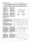
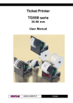
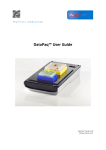
1
FT190 II
USER MANUAL
OEM
All rights reserved. Total or partial reproduction of this manual in whatever form, whether by printed or electronic
means, is forbidden. While guaranteeing that the information contained in it has been carefully checked, CUSTOM
ENGINEERING SPA and other entities utilized in the realization of this manual bear no responsibility for how the
manual is used.
Information regarding any errors found in it or suggestions on how it could be improved are appreciated. Since products are subject to continuous check and improvement, CUSTOM ENGINEERING SPA reserves the right to make
changes in information contained in this manual without prior notification.
Copyright © 2009 CUSTOM ENGINEERING S.p.a. – Italy
CUSTOM ENGINEERING SPA
Str. Berettine 2 - 43010 Fontevivo (PARMA) - Italy
Tel.: +39 0521-680111 Fax: +39 0521-610701
http: www.custom.it
Customer Service Department:
Tel.: +39 059 88 69 587
Email: [email protected]
PRINTER COMPONENTS
A. FT190 II - Front external view
1- Printing mechanism
2- Case
3- Paper output
4- Paper loading label
5- Front panel
6- Paper roll compartment
7- Control panel
1
2
POWER
3
STATUS
4
Print
Feed
7
6
5
User Manual
FT190 II 3
B. FT190 II - Rear external view
1- Power supply connector
2- Paper winder connector
3- Interface connector
4- External “Print” key connector
1
4
3
2
4 FT190 II
User Manual
TABLE OF CONTENTS
1. INTRODUCTION
1.1 MANUAL CONTENTS .............................................................................................................................1-1
1.2 EXPLANATORY USED IN THIS MANUAL ..............................................................................................1-1
1.3 GENERAL SAFETY INFORMATION.......................................................................................................1-1
1.4 UNPACKING THE PRINTER ..................................................................................................................1-2
1.5 PRINTER FEATURES ............................................................................................................................1-2
1.6 PRINTER DESCRIPTION .......................................................................................................................1-3
2. INSTALLATION AND USE
2.1 CONNECTIONS ......................................................................................................................................2-1
2.1.1 Power supply ...................................................................................................................................2-1
2.1.2 Paper winder ...................................................................................................................................2-2
2.1.3 External Print key ............................................................................................................................2-2
2.2 CONFIGURATION...................................................................................................................................2-3
2.3 AUTOTEST..............................................................................................................................................2-4
2.4 HEXADECIMAL DUMP ...........................................................................................................................2-4
2.5 MAINTENANCE ......................................................................................................................................2-4
2.5.1 Changing the paper roll ...................................................................................................................2-4
3. INTERFACES
3.1 RS232 SERIAL ........................................................................................................................................3-1
3.2 CENTRONICS PARALLEL ......................................................................................................................3-3
3.3 CALENDAR CLOCK (optional)................................................................................................................3-4
3.3.1 Adjusting the clock through the keypad ...........................................................................................3-4
4. PRINTER FUNCTIONS
4.1 PRINT DIRECTION .................................................................................................................................4-1
4.2 COMMAND DESCRIPTIONS..................................................................................................................4-2
4.2.1 Command description preliminary remark.......................................................................................4-3
5. TECHNICAL SPECIFICATIONS
5.1 TECHNICAL SPECIFICATIONS..............................................................................................................5-1
5.2 DIMENSIONS ..........................................................................................................................................5-2
6. CHARACTER SETS
6.1 CHARACTER SETS ................................................................................................................................6-1
APPENDIX A - ACCESSORIES AND SPARE PARTS
A.1 ACCESSORIES ..................................................................................................................................... A-1
A.1.1 Power supply ................................................................................................................................. A-1
A.1.2 Paper winder .................................................................................................................................. A-2
A.2 SPARE PARTS....................................................................................................................................... A-2
A.2.1 Supplies ......................................................................................................................................... A-2
User Manual
FT190 II i
TABLE OF CONTENTS
Blank page
ii FT190 II
User Manual
1. INTRODUCTION
1.1 MANUAL CONTENTS
In addition to the Introduction which includes a description of the explanatory notes used in the manual, general
safety information, how to unpack the printer and a brief description of the printer including its basic features,
this manual is organized as follows:
Chapter 1:
Chapter 2:
Chapter 3:
Chapter 4:
Chapter 5:
Appendix:
Contains the information required for correct printer installation and its proper use
Contains information on interface specifications
Contains a description of the printer command set
Contains Technical Specifications of the printer
Contains the character sets (fonts) used by the printer.
Contains a description of printer accessories and spare parts.
1.2 EXPLANATORY USED IN THIS MANUAL
N. B.
Gives important information or suggestions relative to the use of the printer.
WARNING
Information marked with this symbol must be carefully followed to guard against damaging the
printer.
DANGER
Information marked with this symbol must be carefully followed to guard against operator injury
or damage.
1.3 GENERAL SAFETY INFORMATION
•
•
•
•
•
•
•
•
•
•
•
•
Read and keep the instructions which follow.
Follow all warnings and instructions indicated on the printer.
Before cleaning the printer, disconnect the power supply.
Clean the printer with a damp cloth. Do not use liquid or spray products.
Do not operate the printer near water.
Do not use the printer on unstable surfaces that might cause it to fall and be seriously damaged.
Position the printer in such a way as to ensure that the cables connected to it will not be damaged.
Use the type of electrical power supply indicated on the printer label. If in doubt, contact your retailer.
Do not introduce foreign objects of any kind into the printer as this could cause a short circuit or damage
parts that could jeopardize printer functioning.
Do not spill liquids onto the printer.
Do not carry out technical operations on the printer, with the exception of the scheduled maintenance
procedures specifically indicated in the user manual.
Disconnect the printer from the electricity supply and have it repaired by a specialized technician when:
A.
The feed connector has been damaged;
B.
Liquid has seeped inside the printer;
C.
The printer has been exposed to rain or water;
D.
The printer is not functioning normally despite the fact that all instructions in the users
manual have been followed;
E.
The printer has been dropped and its outer casing damaged;
F.
Printer performance is poor;
G.
The printer is not functioning.
User Manual
FT190 II 1-1
1. INTRODUCTION
1.4 UNPACKING THE PRINTER
Remove the printer from the carton, taking care not to damage the packing materials which should be retained
for future shipping/moving. Make sure all components listed below are present and not damaged. If any part is
missing and/or damaged, contact customer service.
1.
2.
3.
4.
Printer
Installation instructions
Paper roll (inside the printer)
Long screws.
1
2
3
4
(Fig.1)
N.B.
Before using the long screws, read the note to paragraph 4.2.
1.5 PRINTER FEATURES
The FT190II is a printer which, in addition to having an innovative design, guarantees high performance and
is reliable and user-friendly.
For these reasons, it is the ideal solution for applications which require the immediate printing of data on a
ticket, whether they be of an industrial, professional or laboratory nature. Typical fields of application are:
weighing systems, receipts (not for tax purposes) as well as for security, controlling and diagnostics purposes.
It has a 200 dpi thermal print mechanism and uses 57.5mm paper rolls. It can print 24 or 40 characters per
line according to the selection made at the setup stage or through a software command.
The FT190II printer is so compact and lightweight that it can be installed extremely easily on any type of
equipment. It is supplied with two interfaces: an RS232 serial and Centronics parallel interface. To select one
or the other interface, some jumpers must be moved. The reception buffer is 1Kbytes. It can also be equipped with a Real Time Clock.
1-2 FT190 II
User Manual
1. INTRODUCTION
1.6 PRINTER DESCRIPTION
The FT190II printer has an ABS casing (1) with a front cover (2) which opens to allow access to the paper
roll and print head. The control panel is located on the front (3) and has a PRINT key, a FEED key and two
LEDs: Power and Status.
POWER
STATUS
Print
2
Feed
3
1
(Fig.2)
• PRINT key
When pressed, in serial causes the “$0D” control character to be transmitted if
enabled during printer setup. In parallel to the PRINT key is the J6 connector which
can be used to connect to an external key (fig.1.1).
• FEED key
When this is pressed, the paper feeds forward manually. If this key is pressed
briefly, when the RTCK option is installed, the date and time of day is printed.
• The POWER LED
Indicates that the printer is receiving a digital power supply.
• The STATUS LED
When flashing, signals that the paper is finished. When lit steadily, it signals the
presence of an error (head power supply too high or too low or head temperature
too high).
User Manual
FT190 II 1-3
1. INTRODUCTION
Blank page
1-4 FT190 II
User Manual
2. INSTALLATION AND USE
2.1 CONNECTIONS
(Fig.2.1)
2.1.1 Power supply
The printer is equipped with a standard 4-pin male AMPMODU1-type connector (J4) for the power supply
(see Fig. 2.1). The signals on the connector pins are as follows:
WARNING:
Respect the polarity of the power supply.
5V VERSION
PIN
SIGNAL
NOTES
1
GND
Ground signal
2
GND
Ground signal
3
+ VT: da 4.5 Vdc a 7 Vdc
(Head power supply)
4
+ VCC: 5 Vdc ± 7%
(Logic power supply)
(Tab. 2.1)
9-40V VERSION
PIN
SIGNAL
NOTES
1
GND
Ground signal
2
GND
Ground signal
3
from 9 Vdc to 40 Vdc
(Head power supply)
4
N.C.
Not connected
(Tab. 2.2)
User Manual
FT190 II 2-1
2. INSTALLATION AND USE
2.1.2 Paper winder
Connector J5 (fig.2.1) is used to feed the external paper winder. The position and function of the signals are
given below in Table 2.3.
PIN
SIGNAL
1
MOTOR +
2
MOTOR (Tab. 2.3)
2.1.3 External Print key
An external print key may be connected to connector J6 (fig. 2.1). The polarity and function of the signals are
given in Table 2.4.
PIN
SIGNAL
1
PRINT
2
GND
(Tab. 2.4)
2-2 FT190 II
User Manual
2. INSTALLATION AND USE
2.2 CONFIGURATION
The FT190II enables the configuration of the printer default parameters.This procedure is enabled by holding
down the PRINT and FEED keys while switching on, with the jumper JP2 (Fig. 3.1) present on the printer
card open. After this, each time the PRINT key is pressed, the parameter is modified and its current value is
printed. Once the required value has been obtained, press the FEED key to proceed to the next parameter,
and so on. Once all the parameters have been run through, the printing of a message signals the end of the
setting procedure. The parameters affected during configuration are:
•
•
•
•
•
•
•
•
Number of columns: 24 Columns (16x24) D, 40 Columns (9x24).
Print direction: Normal or Reverse D.
Character dimension: SmallD, double width, double height, expanded.
Character set: Font1 D or Font2.
Automatic feed: CR disabled or CR enabledD.
Autofeed (1): attivato D o disattivato.
Velocità/Consumo: LowD, Medium, High.
Selection of the red intensity (2): 0, 1, 2, 3, 4, 5 D, 6, 7.
If present serial interface :
• Baud Rate: 19200, 9600 D, 4800, 2400, 1200, 600, 300.
• Protocol: 8, N, 1D (8 bit, parity none, 1 Stop bit)
8, E, 1 (8 bit, parity even, 1 Stop bit)
8, O, 1 (8 bit, parity odd, 1 Stop bit)
7, N, 2 (7 bit, parity none, 2 Stop bit)
7, E, 1 (7 bit, parity even, 1 Stop bit)
7, O, 1 (7 bit, parity odd, 1 Stop bit)
• Flow control: CTS, RTS, XON, XOFF D.
• PRINT key setting: Null PRINT key, Enables $0D character transmission on pressing PRINT keyD.
If present parallel interface :
• Length of data: 7 D, 8 bits/car.
• Reception buffer dimension: 1K byteD , 24 byte.
If present RTCK (real time clock):
• Real Time Clock setting: Enable RTCK D, Disable RTCK.
• Printing seconds setting: Enable seconds, Disable secondsD.
General note:
Note(1):
Note(2):
The parameters marked with the symbol D represent the default values.
If the function is enabled when the printer receives a characters number equal to the line
buffer the next character will place on the left margin in a new line.
Using two-colour thermal paper is possible to set different red tonality.
The settings made are saved on the EEPROM (non volatile memory).
User Manual
FT190 II 2-3
2. INSTALLATION AND USE
2.3 AUTOTEST
To run the autotest, hold down the FEED key, while switching on the printer. The autotest causes the printing
of the printer’s current setting data and the printing of the complete ASCII character set.
2.4 HEXADECIMAL DUMP
If the PRINT key is held down during switching on, the printer enters Hexadecimal Dump mode. This function
is used for the diagnostics of characters received in serial or parallel. In fact, these are printed in hexademical code together with the corresponding ASCII code.
2.5 MAINTENANCE
2.5.1 Changing the paper roll
To change the paper roll, proceed as follows:
1. Open the printer cover and press down the swinging support of the print mechanism at the point marked
PUSH;
2. Insert the end of the paper roll in the slit of the print mechanism and position the paper roll so that it rotates in the right direction, as shown in the figure;
3. The paper is automatically pulled by the roller for 3 or 4 centimetres;
4. Tear off the paper and re-close the cover.
(Fig.2.2)
WARNING
Make sure the paper edge is straight before inserting it in the
machine.
2-4 FT190 II
User Manual
3. INTERFACES
(Fig.3.1)
The selection of the RS232 or CENTRONICS interface is made through the 20-contact strip:
When the strip is placed in position 1-2 (fig.3.1) the standard CENTRONICS interface is selected; when placed in position 2-3 the RS232 interface is selected.
3.1 RS232 SERIAL
The printer has an RS232 serial interface and is connected using a 25-pin female connector. The communication signals used for serial protocol are TXD, RXD and RTS if the RTS/CTS protocol was selected or TXD
and RXD if the XON/XOF protocol was selected. Given below are the signals present on the connector:
PIN
SIGNAL
DIRECTION
DESCRIPTION
1
N.C.
-
Not connected
2
TXD
Output
Data transmission
3
RXD
Input
Data reception
4
RTS
Output
Same as DTR signal
7
SG
-
Groung signal
20
DTR
Output
When the DTR/DSR command is selected, this signal indicates when the printer is busy. SPACE indicates that the
printer is ready to receive data and MARK that the printer
is busy.
23
GND
-
Ground
24
GND
-
Ground
25
GND
-
Ground
(Tab. 3.1)
User Manual
FT190 II 3-1
3. INTERFACES
The diagrams below give sample connections between the printer and Personal Computer using a 25- and
9-pin female connector.
(Fig.3.2)
1
2
3
4
5
6
7
8
9
10
11
12
13
14
15
16
17
18
19
20
21
22
23
24
25
TXD
RXD
TXD
RXD
RTS
CTS
DSR
SIGNAL GND
DCD
DTR
PRINTER
(Fig.3.3)
1
2
3
4
5
6
7
8
9
10
11
12
13
14
15
16
17
18
19
20
21
22
23
24
25
TXD
RXD
RTS
PC
DCD
RXD
TXD
GND
DSR
GND
CTS
1
2
3
4
5
6
7
8
9
DTR
PRINTER
3-2 FT190 II
1
2
3
4
5
6
7
8
9
10
11
12
13
14
15
16
17
18
19
20
21
22
23
24
25
User Manual
PC
3. INTERFACES
3.2 CENTRONICS PARALLEL
The printer has a Centronics parallel interface and is connected using a 25-pin female connector. The following signals can be used for parallel communication:
1.
2.
3.
4.
7 or 8 bit data bus;
STROBE signal that indicates data validity;
BUSY signal that indicates if printer is available to receive data;
ACK signal for data read confirmation.
Given below are the signals present on the connector:
PIN
SIGNAL
DIRECTION
1
Strobe
Input
2
Data bit 0
Input
3
Data bit 1
Input
4
Data bit 2
Input
5
Data bit 3
Input
6
Data bit 4
Input
7
Data bit 5
Input
8
Data bit 6
Input
9
Data bit 7
Input
10
ACK
Output
11
BUSY
Output
12
PAPER END
Output
13
HIGHT
Output
14
N.C.
-
15
FALT
Output
16
RESET
Input
17-25
GND
(Tab. 3.2)
User Manual
FT190 II 3-3
3. INTERFACES
3.3 CALENDAR CLOCK (optional)
The Real Time Clock is available as an option.
Printing and adjustment of the clock are managed by a series of control characters.
N.B.
For the real time clock control characters, please refer to the description of the printer command
sets in chapter 4.
3.3.1 Adjusting the clock through the keypad
The time and date can be adjusted using the PRINT and FEED keys on the printer’s front panel. To set,
proceed as follows:
•
•
•
•
While holding down the FEED key, press the PRINT key. The printer will print the time and date with an
arrow indicating the digit to be modified;
Each time the PRINT key is pressed, the digit marked by the arrow will increase and an updated version
will be printed;
To proceed to modify another digit, press the FEED key again. Each time the printer will print the updated time and date, highlighting with an arrow the currently selected digit;
To terminate the setting procedure, press PRINT and FEED at the same time.
3-4 FT190 II
User Manual
4. PRINTER FUNCTIONS
4.1 PRINT DIRECTION
The printer has two printing directions wich can be selected by means of the control characters: normal and
reverse.
(Fig.4.1)
FT190II
Panel printer
Normal mode
PAPER OUTFEED DIRECTION
FT190II
Panel printer
Reverse mode
User Manual
FT190 II 4-1
4. PRINTER FUNCTIONS
4.2 COMMAND DESCRIPTIONS
The command table lists all the commands for the management of the printer functions. These commands
can be transmitted to the printer with both the serial and parallel interfaces; if, however, the parallel interface
is being used, the user will not be able to receive any kind of response, as this interface is mono-directional.
The commands can be transmitted to the printer at any moment, but they will only be carried out when the
characters previously transmitted have been printed or the commands previously transmitted have been
carried out. There are no commands with priority status; all the commands are carried out when the circular
buffer is free to do so.
COMMAND DESCRIPTION TABLE
(Tab.4.1)
HEX Com.
ASCII Com.
Description
$00
Prints in small characters
$01
Prints in double width
$02
Prints in double height
$03
Expanded printing
$04
Restore small character printing
$0A
LF
Forward feeds one line
(n) $0B
(n) VT
Forward feeds (n) line
$0D
CR
Print line buffer
$0F
Sets CRLF mode
$11
Graphic mode
$12
Print time and date
$13
Sets time and date
$14
Transmits time and date in serial
$17
Prints 1st programmable character
$18
Prints 2nd programmable character
$19
Prints 3rd programmable character
$1A
Prints 4th programmable character
$1C
Prints 5th programmable character
$1D
Prints 6th programmable character
$1E
Prints 7th programmable character
$1F
Prints 8th programmable character
$1B $40
ESC @
Resets the printer
$1B $41
ESC A
Executes [n] dots line feed
$1B $44
ESC D
Enter date in print buffer
$1B $4E
ESC N
Sets normal mode printing
$1B $52
ESC R
Sets reverse mode printing
$1B $53
ESC S
Enables printing of seconds
$1B $54
ESC T
Enter time in print buffer
$1B $55
ESC U
Enter date (mm :dd :yy) in print buffer
$1B $58
ESC X
Prints in red
$1B $78
ESC x
Prints in black
$1B $42
ESC B
Sets character font 1
$1B $62
ESC b
Sets character font 2
4-2 FT190 II
User Manual
4. PRINTER FUNCTIONS
HEX Com.
ASCII Com.
Description
$1B $49
ESC I
Selects 24 columns
$1B $69
ESC i
Selects 40 columns
(aa) $1B $72
(aa) ESC r
Reads data at an address (aa)
(aadd) $1B $77
(aadd) ESC w
Write data (dd) in an address (aa)
(dd) $1B $47
(dd) ESC G
Write value (dd) in option register
(dd) $1B $4B
(dd) ESC K
Write value (dd) in option register 1
(dd) $1B $4D
(dd) ESC M
Write value (dd) in print mode
$1B $70
ESC p
Transmits option register in serial
$1B $6B
ESC k
Transmits option register 1 in serial
$1B $6D
ESC m
Transmits print mode in serial
$1B $73
ESC s
Transmits next character in serial
(dd) $1B $61
(dd) ESC a
Selects number of dot spaces
$1B $4A
ESC J (n)
Load programmable character
$1B $57
ESC W
Prints graphic line of 200 dpi
$1B $63
ESC c
Management of bar code printing
$1B $51
ESC Q
Enables underlining
$1B $71
ESC q
Disables underlining
A more detailed description of the single commands can be found below.
4.2.1 Command description preliminary remark
The first heading line (grey colour) is reported the hexadecimal command value. The next fields give all the
information useful to use the command.
[Name]
[Format]
[Range]
[Description]
[Notes]
[Default]
[Reference]
[Example]
LEGEND
$
{}
n, m, t, x, y
Command title
ASCII, hexadecimal and decimal command value.
Limits of the values the command and its variables can take
Description of command function
Additional information about command use and settings.
Default value of the command and its variables.
Pertaining commands related to described command.
indicates the representation of the command hexadecimal value (for example $40 means
HEX 40).
indicates an ASCII character not performable.
are optional parameters that can have different values.
User Manual
FT190 II 4-3
4. PRINTER FUNCTIONS
$00
[Name]
[Format]
[Range]
[Description]
[Notes]
[Default]
[Reference]
[Example]
$01
[Name]
[Format]
[Range]
[Description]
[Notes]
[Default]
[Reference]
[Example]
$02
[Name]
[Format]
[Range]
[Description]
[Notes]
[Default]
[Reference]
[Example]
$03
[Name]
[Format]
[Range]
[Description]
[Notes]
[Default]
[Reference]
[Example]
4-4 FT190 II
Small character printing
ASCII
{}
Hex
00
Decimal
0
The printer prints in small characters (normal).
• The commands $00 - $09 do not cancel the print buffer
• The commands which modify the direction of the characters are only active at the beginning of the line
Setting in option register by means of front keys.
$01, $02, $03, $04
Double width printing
ASCII
{}
Hex
01
Decimal
1
The printer prints in double width format
• The commands $00 - $09 do not cancel the print buffer
• The commands which modify the direction of the characters are only active at the beginning of the line
Setting in option register by means of front keys.
$00, $02, $03, $04
Double height printing
ASCII
{}
Hex
02
Decimal
2
The printer prints in double height format.
• The commands $00 - $09 do not cancel the print buffer
• The commands which modify the direction of the characters are only active at the beginning of the line
Setting in option register by means of front keys.
$00, $01, $03, $04
Expanded printing
ASCII
{}
Hex
03
Decimal
3
The printer prints in expanded character mode.
• The commands $00-$09 do not cancel the print buffer
• the commands which modify the dimensions of the characters are only active at the
beginning of the line
Impostazione nell’option register tramite i tasti frontali
$00, $01, $02, $04
User Manual
4. PRINTER FUNCTIONS
$04
[Name]
[Format]
[Range]
[Description]
[Notes]
[Default]
[Reference]
[Example]
$0A
[Name]
[Format]
[Range]
[Description]
[Notes]
[Default]
[Reference]
[Example]
(n) $0B
[Name]
[Format]
[Range]
[Description]
[Notes]
[Default]
[Reference]
[Example]
$0D
[Name]
[Format]
[Range]
[Description]
[Notes]
[Default]
[Reference]
[Example]
Restore small character printing
ASCII
{}
Hex
04
Decimal
4
The printer resumes printing with small characters.
• The commands $00-$09 do not cancel the print buffer
• The commands which modify the dimensions of the characters are only active at the
beginning of the line
Setting in the option register by means of the front keys.
$00, $01, $02, $03
Forward feeds one line
ASCII
LF
Hex
0A
Decimal
10
Forward feeds one line equivalent to a line of print.
• This command brings about the printing of the contents of the line buffer.
$0B
Forward feeds (n) lines
ASCII
n
VT
Hex
n
0B
Decimal
n
11
0≤n≤9
Carries out the number of line feeds specified by n number.
• When n=0 the command is ignored.
• This command clears the line buffer.
$0A
Print the line buffer
ASCII
CR
Hex
0D
Decimal
13
This command prints the line buffer.
• If the line buffer is empty, the command is ignored.
• If the CRLF option is set, this command is ignored and printing can only be ordered
through the command $0A.
$0F
User Manual
FT190 II 4-5
4. PRINTER FUNCTIONS
$0F
[Name]
[Format]
[Range]
[Description]
[Notes]
[Default]
[Reference]
[Example]
$11
[Name]
[Format]
[Range]
[Description]
[Notes]
Set CRLF mode
ASCII
{}
Hex
0F
Decimal
15
Inhibits the command $0D maintaining enabled only the command $0A for printing.
• This command clears the line buffer
• On switching on the default value is in the Option Register.
Setting in the option register by means of the front keys
$0D
Graphic mode
ASCII
{}
Hex
11
Decimal
17
Enables graphic mode: a line in 24 column mode corresponds to 144 horizontal dots
divided into 24 blocks of 6 dots each; a line in 40 column mode corresponds to 240 horizontal dots divided into 40.
• To obtain graphic printing, enter the command $11 at the beginning of each line. The
format of the byte in graphic configuration is:
X
R
P6
P5
P4
P3
P2
P1
D7
D6
D5
D4
D3
D2
D1
D0
where :
X is not used (0 is recommended);
R must be fixed at level 1;
P1 ÷ P6 are the graphic dot data (1 prints, 0 does not print). The P6 bit of the string of
dots transmitted is printed on the left and the others follow from left to right (P5, P4, P3,
P2,P1) as shown:
[Default]
[Reference]
[Example]
$12
[Name]
[Format]
[Range]
[Description]
[Notes]
[Default]
[Reference]
[Example]
4-6 FT190 II
1st byte -->
2nd byte -->
3rd byte -->
P6, P5,P4,P3,P2,P1
P6, P5,P4,P3,P2,P1
P6, P5,P4,P3,P2,P1
• To print a line of dots, transmit: $11, n x $7F (where n is the number of characters per
line), $0D.
• To print an empty line, transmit: $11, $40, $0D.
Print time and date
ASCII
{}
Hex
12
Decimal
18
Prints the time and date in the following format:
hh : mm
dd - mm - yy
• If seconds printing is enabled, the format will be:
hh : mm : ss
dd - mm - yy
• The command resets the line.
$13, $14
User Manual
4. PRINTER FUNCTIONS
$13
[Name]
[Format]
[Range]
[Description]
[Notes]
[Default]
[Reference]
[Example]
Set time and date
ASCII
{}
Hex
13
Decimal
19
This command sets the time and date in two possible ways: the first uses the 24-hour
clock and the second the 12-hour am/pm clock. In the first case, transmit the 10 ASCII
characters representing the time and the date followed by $13 and in the second case
transmit the 10 ASCII characters representing the time and the date preceded by “A” or
“P” and followed by $13.
• It is advisable to transmit the command $0D first, in order to empty the print buffer.
$12, $14
• To set the time 12:45 on 19-01-93, transmit:
1
2
4
5
1
9
0
1
9
3
$13
$31
$32
$34
$35
$31
$39
$30
$31
$39
$33
$13
• To set the time A12:45 on 19-01-93, transmit:
$14
[Name]
[Format]
[Range]
[Description]
[Notes]
[Default]
[Reference]
[Example]
$17,...$1F
[Name]
[Format]
[Range]
[Description]
[Notes]
[Default]
[Reference]
[Example]
A
1
2
4
5
1
9
0
1
9
3
$13
$41
$31
$32
$34
$35
$31
$39
$30
$31
$39
$33
$13
Transmit the time and date in serial
ASCII
{}
Hex
14
Decimal
20
Transmit the time and date on the serial port in 11 ASCII character format:
hours/minutes/day/month/year + (CR) $0D
$12, $13
Print 1st (...8th) programmable character
ASCII
{}
Hex
17,... 1F
Decimal
23,... 31
This command prints the corresponding programmable character.
BITMAP contained in flash
$17, $18, $19, $1A, $1C, $1D, $1E, $1F
User Manual
FT190 II 4-7
4. PRINTER FUNCTIONS
$1B $40
[Name]
[Format]
[Range]
[Description]
[Notes]
[Default]
[Reference]
[Example]
$1B $41
[Name]
[Format]
[Range]
[Description]
[Notes]
[Default]
[Reference]
[Example]
$1B $44
[Name]
[Format]
[Range]
[Description]
[Notes]
[Default]
[Reference]
[Example]
$1B $4E
[Name]
[Format]
[Range]
[Description]
[Notes]
[Default]
[Reference]
[Example]
4-8 FT190 II
Resets the printer
ASCII
ESC
Hex
1B
Decimal
27
@
40
64
Cancels all the data in the print buffer and resets the printer mode, restoring the mode
which was enabled at the moment of switching on.
• Same as hardware reset.
• After the command has been transmitted, 1.5 seconds elapse before the printer is enabled
This can be useful during switching on in order to avoid the sending of false characters
during initialization by the master device
Executes [n] dots line feed
ASCII
ESC A
Hex
1B
41
Decimal
27
65
nH
nH
nH
nL
nL
nL
Executes [n] dots line feed
Enters the date in the print buffer
ASCII
ESC D
Hex
1B
44
Decimal
27
68
Enters in the buffer the date of the calender clock installed inside the printer, in the following format: dd - mm -yy.
• The date is printed in 8 characters: if there is not enough space in the buffer, it will not
be printed
• It does not zero-set the line buffer
$1B $54, $1B $55
If you wish to write:
transmit
to print just the date
DATE: 11-09-93 TEST OK
DATE: $1B $44 TEST OK $0D
$1B $44 $0D
Set normal mode printing
ASCII
ESC N
Hex
1B
4E
Decimal
27
78
Select normal mode printing:the receipt feeds out of the printer with the printing upside
down running from right to left.
Setting in option register by means of front keys
$1B $52
User Manual
4. PRINTER FUNCTIONS
$1B $52
[Name]
[Format]
[Range]
[Description]
[Notes]
[Default]
[Reference]
[Example]
$1B $53
[Name]
[Format]
[Range]
[Description]
[Notes]
[Default]
[Reference]
[Example]
$1B $54
[Name]
[Format]
[Range]
[Description]
[Notes]
[Default]
[Reference]
[Example]
$1B $55
[Name]
[Format]
[Range]
[Description]
[Notes]
Set reverse mode printing
ASCII
ESC R
Hex
1B
52
Decimal
27
82
Selects printing in reverse mode: the receipt feeds out of the printer with the printing in
normal mode running from left to right.
Setting in option register by means of front keys
$1B $4E
Enables printing of seconds
ASCII
ESC S
Hex
1B
53
Decimal
27
83
Enables the printing of the seconds when the time of day is requested through command
$1B $54.
Setting in option register by means of front keys
$1B $54
Enters the time in the print buffer
ASCII
ESC T
Hex
1B
54
Decimal
27
84
Enters in the buffer the time on the calendar clock installed inside the printer, in the following format: hh:mm
• The time is printed in 5 characters and, if the seconds option is enabled, in 8 characters:
if there is not enough space in the buffer, it will not be printed
• It does not zero-set the line buffer
$1B $44, $1B $53, $1B $55
If you wish to write:
HOUR: 16:45 TEST OK
transmit
HOUR: $1B $54 TEST OK $0D
to print just the date
$1B $54 $0D
Enter the date (mm - dd - yy) in the print buffer
ASCII
ESC U
Hex
1B
55
Decimal
27
85
Enter in the buffer the date on the calendar clock installed inside the printer, American
style: mm-dd-yy
• The date is printed in 8 characters: if there is not enough space in the buffer, it will not
be printed
User Manual
FT190 II 4-9
4. PRINTER FUNCTIONS
• It does not zero-set the line buffer
[Default]
[Reference]
[Example]
$1B $58
[Name]
[Format]
[Range]
[Description]
[Notes]
[Default]
[Reference]
[Example]
$1B $78
[Name]
[Format]
[Range]
[Description]
[Notes]
[Default]
[Reference]
[Example]
$1B $42
[Name]
[Format]
[Range]
[Description]
[Notes]
[Default]
[Reference]
[Example]
$1B $62
[Name]
[Format]
[Range]
[Description]
[Notes]
[Default]
[Reference]
[Example]
4-10 FT190 II
$1B $44, $1B $54
If you wish to write:
transmit
to print just the date
DATE: 09-11-93 TEST OK
DATE: $1B $55 TEST OK $0D
$1B $55 $0D
Prints in red
ASCII
Hex
Decimal
X
58
88
ESC
1B
27
After receiving this command the printer prepares itself to print in red.
Prints in black
ASCII
ESC
Hex
1B
Decimal
27
x
78
120
After receiving this command the printer prepares itself to print in black.
Sets font 1
ASCII
Hex
Decimal
ESC
1B
27
B
42
66
Selects the first character font.
• The complete font is printed during the autotest. Some codes are not standard: $60,
$7B, $7C, $7D, $7E, $7F, $8D, $ED, $FA, $FF
Setting in the option register by means of the front keys
$1B $62
Sets font 2
ASCII
Hex
Decimal
ESC
1B
27
b
62
98
Selects the second character font.
• The complete font is printed during the autotest. The font contains cyrillic characters.
Setting in the option register by means of the front keys
$1B $42
User Manual
4. PRINTER FUNCTIONS
$1B $49
[Name]
[Format]
[Range]
[Description]
[Notes]
[Default]
[Reference]
[Example]
$1B $69
[Name]
[Format]
[Range]
[Description]
[Notes]
[Default]
[Reference]
[Example]
(aa) $1B $72
[Name]
[Format]
[Range]
[Description]
[Notes]
[Default]
[Reference]
[Example]
Select 24 columns
ASCII
ESC
Hex
1B
Decimal
27
I
49
73
On receiving this command, the printer enters 24-column per line printing mode
$1B $69
Select 40 columns
ASCII
ESC
Hex
1B
Decimal
27
i
69
105
On receiving this command, the printer enters 40-column per line printing mode
$1B $49
Read data at an address (aa)
ASCII
aH
aL
ESC
Hex
aH
aL
1B
Decimal
aH
aL
27
r
72
114
Read a memory location (EEPROM) at address a :
aH is the most significant nibble of a expressed in ASCII
aL is the least significant nibble of a expressed in ASCII
• There are 256 legible locations (from $00 to $FF)
The whole memory bank contains the value $20 by default
$1B $77
To read address $01, transmit in ASCII: $30 $31 $1B $72
If address $01 contains $A5, we will receive: $41 $35
User Manual
FT190 II 4-11
4. PRINTER FUNCTIONS
(aadd) $1B $77
[Name]
[Format]
[Range]
[Description]
[Notes]
[Default]
[Reference]
[Example]
(dd) $1B $47
[Name]
[Format]
[Range]
[Description]
Write data (dd) in address (aa)
ASCII
aH
aL
dH
Hex
aH
aL
dH
Decimal
aH
aL
dH
Modify the configuration register.
(dd) are two ascii characters which represent the hexadecimal code for the programming of
the register; in the following table is indicated the value of dd send it in a byte format:
1
2
3
4
5
6
7
4-12 FT190 II
w
77
119
Write the value (dd) in the option register
ASCII
dH
dL
ESC G
Hex
dH
dL
1B
47
Decimal
dH
dL
27
71
0
[Default]
[Reference]
[Example]
ESC
1B
27
Save datad in addressa in the memory (EEPROM):
aH is the most significant nibble of a expressed in ASCII
aL is the least significant nibble of a expressed in ASCII
dH is the most significant nibble of d expressed in ASCII
dL is the least significant nibble ofd expressed in ASCII
• There are 256 writable locations (from $00 to $FF); the data maximum is $FF (255) and
both the addresses and the data must be expressed in ASCII on two bytes
The whole memory bank contains the value $20 by default
$1B $72
To save the data $A5 in the address $01, transmit:
$30 $31 $41 $35 $1B $77
BIT
[Notes]
dL
dL
dL
OFF/ON
HEX
Decimal
Off
00
0
setting of real time clock disabled
FUNCTION
On
01
1
setting of real time clock enabled
Off
00
0
Print direction normal
On
02
2
Print direction reverse
Off
00
0
number bits in parallel reception 8
On
04
4
number bits in parallel reception 7
Off
00
0
Printing of seconds disabled
On
08
8
Printing of seconds enabled
Off
00
0
CR ($0D) enabled
On
10
16
CR ($0D) disabled
Off
00
0
On
20
32
Off
00
0
Selection font 1
On
40
64
Selection font 2
Off
00
0
Reception buffer = 1Kbyte
On
80
128
Reception buffer = N° columns
• The setting is memorized in the EEPROM and assumed as the default value the next
time the printer is switched on
$1B $4B
To send setting byte 00001001 ($09):
User Manual
$30 $39 $1B $47
4. PRINTER FUNCTIONS
(dd) $1B $4B
[Name]
[Format]
[Range]
[Description]
Write the value (dd) in the option register 1
ASCII
dH
dL
ESC K
Hex
dH
dL
1B
4B
Decimal
dH
dL
27
75
Modifies the configuration register.
(dd) are two ASCII characters representing the hexadecimal code for the programming
of the register :
BIT
0
[Notes]
[Default]
[Reference]
[Example]
(dd) $1B $4D
[Name]
[Format]
[Range]
[Description]
[Notes]
[Default]
[Reference]
[Example]
$1B $70
[Name]
[Format]
[Range]
[Description]
[Notes]
[Default]
[Reference]
[Example]
OFF/ON
HEX
Decimal
Off
00
0
Sets 24 columns
FUNCTION
On
01
1
Sets 40 columns
• The setting is memorized in the EEPROM and assumed as default value the next time
the printer is switched on
$1B $47
To send setting byte 00001001 ($09):
$30 $39 $1B $47
Writes the value (dd) in the print mode
ASCII
dH
dL
ESC M
Hex
dH
dL
1B
4D
Decimal
dH
dL
27
77
Sets the print mode default parameters:
$00 small character printing
$01 double width printing
$02 double height printing
$03 expanded printing
• The setting is stored in the EEPROM
Setting by means of the front keys
$1B $6D
For double height printing, transmit: $30 $32 $1B $4D
Transmit the configuration register in serial
ASCII
ESC p
Hex
1B
70
Decimal
27
112
Transmit the option register byte on the serial port.
• If the printer is using the parallel protocol, nothing with be transmitted
$1B $47, $1B $4B, $1B $6B
The response is on two bytes. E.g., if you receive: $30 $39
it means that the default configuration is 00001001
User Manual
FT190 II 4-13
4. PRINTER FUNCTIONS
$1B $6B
[Name]
[Format]
[Range]
[Description]
[Notes]
[Default]
[Reference]
[Example]
$1B $6D
[Name]
[Format]
[Range]
[Description]
[Note]
[Default]
[Reference]
[Example]
$1B $73
[Name]
[Format]
[Range]
[Description]
[Notes]
[Default]
[Reference]
[Example]
(dd) $1B $61
[Name]
[Format]
[Range]
[Description]
[Notes]
[Default]
[Reference]
[Example]
4-14 FT190 II
Transmits the second configuration register in serial
ASCII
ESC k
Hex
1B
6B
Decimal
27
107
Transmits in serial the value of the second configuration register in ASCII format on two
characters which represent the hexadecimal value.
• If the printer is using the parallel protocol, nothing with be transmitted
$1B $4B
The response is on two bytes. E.g. if you receive: $30 $39
it means that the default register is 00001001
Transmits the print mode in serial
ASCII
ESC m
Hex
1B
6D
Decimal
27
109
Transmits the print mode configuration on the serial port.
• If the printer is using the parallel protocol, nothing with be transmitted
Setting in the option register by means of the front keys
$1B $42
The response is on two bytes. E.g. if you receive: $30 $32
it means that printing is in double height mode
Transmits the next character in serial
ASCII
ESC s
Hex
1B
73
Decimal
27
115
Transmits the next character it receives on the serial port.
If you transmit: ESC s A
the last character, A, will not be printed but immediately transmitted on the serial line
Selects the number of dot spaces
ASCII
dd
ESC a
Hex
dd
1B
61
Decimale
dd
27
97
(dd) are two ASCII characters which identify a hexadecimal byte and correspond to the
number of dot lines between one print line and another
=0
User Manual
4. PRINTER FUNCTIONS
$1B $4A
[Name]
[Format]
[Range]
[Description]
[Notes]
[Default]
[Reference]
[Example]
$1B $57
[Name]
[Format]
[Range]
[Description]
Load the programmable character
ASCII
ESC J
(n)
Hex
1B
4A
(n)
Decimal
27
74
(n)
(n) corresponds to the character number, i.e. between 1 and 8.
The bitmap that represents the character is contained in the next 10 bytes expressed in
binary code. The formatting of these bytes is as follows:
bit
7
6
5
4
3
2 1
0
0
1
d
d
d
d d
d
● To modify these bit maps, a firmware upgrade is required.
The 8 characters available on switching on are loaded with a bitmap contained in the
printer’s flash.
If you wish the symbol of the code $1F to be #, transmit ESC J 2 followed by the 10 bytes
making up the character:
$1B $4A $32 $52 $52 $52 $7F $52 $52 $7F $52 $52 $52
Print a graphic line at 200 dpi
ASCII
ESC W
Hex
1B
57
Decimal
27
87
After receiving this command, the printer waits for 48 bytes which correspond to an entire
graphic line. In fact, 48 bytes of 8 bits each correspond to 384 dots per line.
[Notes]
[Default]
[Reference]
[Example]
User Manual
FT190 II 4-15
4. PRINTER FUNCTIONS
$1B $63
[Name]
[Format]
[code]
[height]
[position]
Management of bar code printing
ASCII
ESC c
Hex
1B
63
Decimal
27
99
[Range]
[Description]
[ASCII code]
I
C
B
e
E
[height]
[position]
[options]
[options]
[length]
[data]
Type of bar code
Interleved 2/5
Code 39
CodaBar
EAN8
EAN13
Number of dot lines in 1/8 mm. units.
Left hand margin, expressed in 1/8 mm. units.
bit
bit 0
bit 1
bit0: check digit
is not printed is printed
bit3,2: HRI
0=no 1=above
2=below
3=above & below
bit5,4: size
0=normal
1=double 2=triple 3=quadruple
[maximum length]
Interleaved 2/5
= 12 characters
Code 39
= 10 characters
CodaBar
= 10 characters
EAN8
= 8 characters
EAN13
= 13 characters
[data]
Expressed in ASCII
[Notes]
[Default]
[Reference]
[Example]
$1B $51
[Name]
[Format]
[Range]
[Description]
[Notes]
[Default]
[Reference]
[Example]
$1B $71
[Name]
[Format]
[Range]
[Description]
[Notes]
[Default]
[Reference]
[Example]
4-16 FT190 II
Enable underlined printing
ASCII
ESC Q
Hex
1B
51
Decimal
27
81
After this command has been received, the characters are printed underlined.
$1B $71
Disables underlined printing
ASCII
ESC q
Hex
1B
71
Decimal
27
113
Annuls underlined printing
$1B $51
User Manual
4. PRINTER FUNCTIONS
Blank page
User Manual
FT190 II 4-17
5. TECHNICAL SPECIFICATIONS
5.1 TECHNICAL SPECIFICATIONS
The main technical features of the printer are listed in Table 5.1.
(Tab.5.1)
Columns
24
40
Normal
2x3
1x3
Double height
2x6
1x6
Double width
4x3
2x3
Expanded
4x6
2x6
0,125 x 0,125
0,125 x 0,125
144
240
Lines / sec
30
30
Characters / sec
220
320
Feed (lines / sec)
53
53
Line buffer
24
40
Character (L x H mm)
Graphic dot
Custom emulation dots per line
Print speed (speed/current = normal)
Print buffer
1 Kbyte
Print method
Thermal dot matrix
Character matrix
16x24
8x24
Print direction
Normal or reverse
Character set
Normal and extended
Paper roll dimension
58 ± 1mm x Ø 50 mm max
Standard interfaces
RS232 or Centronics
Double or single 5 Vdc ± 10%
Single 9-40 Vcc optional
Power supply
Absorption (with 5 Volt power supply)
Selection “Speed/current = NORMAL”
Average (1)
1,2 A
Stand by
60 mA
Environmentals conditions
Operating temperature
Operating humidity
0°C ÷ +50°C
20-85% (no condensing)
Storage temperature / Humidity
-25 °C – +70 °C / 10% - 90%
Real time clock
9 - 40 Vcc Power supply
Options
NOTE:
(1)
Referred to a standard CUSTOM receipt (L=10cm, Density = 12,5% dots on).
User Manual
FT190 II 5-1
5. TECHNICAL SPECIFICATIONS
5.2 DIMENSIONS
The dimensions of the panel printer are shown in the figure below. With the screws fitted in the printer,
the maximum thickness of the panel is 5 mm; using the two additional screws provided, the printer can be
mounted on panels with a maximum thickness of 15 mm. For even thicker panels, use longer M3 screws.
(Fig.5.1)
5-2 FT190 II
User Manual
6. CHARACTER SETS
6.1 CHARACTER SETS
The printer has two characters sets, each containing 224 characters (font 1 and font 2), which can be called
up through the programming (paragraph 2.2) or through the control characters (paragraph 4.2).
FONT 1
FONT 2
(Fig.6.1)
(Fig.6.2)
User Manual
FT190 II 6-1
6. CHARACTER SETS
Blank page
6-2 FT190 II
User Manual
APPENDIX A - ACCESSORIES AND SPARE PARTS
A.1 ACCESSORIES
A.1.1 Power Supply
VADJ
The following figure illustrates the power supply provided by Custom to be used for printer operation. The
power supply is available in 3 models:
• PPSPS-025-05 for the 5V version
• PPSPS-025-12 and PPSPS-025-24 for the 9-40V version.
+V
OUT
+V
-V
-V
N
N
IN
L
L
PE
PE
(Fig. A.1)
(Tab. A.1)
Input specifications
Input voltage
85Vac to 264 Vac
Input frequency
47 Hz to 63 Hz
PPSPS-025-05 Output specifications
Output voltage
Output current
5V
Maximum
5.0 A
PPSPS-025-12 Output specifications (for 9-40 VDC version)
Output voltage
Output current
12 V
Maximum
2.1 A
PPSPS-025-24 Output specifications (for 9-40 VDC version)
Output voltage
Output current
24 V
Maximum
1.1 A
User Manual
FT190 II A-1
APPENDIX A - ACCESSORIES AND SPARE PARTS
A.1.2 Paper winder
The AV05 model paper winder can be connected to the printer at the J5 connector.
(Fig. A.2)
A.2 SPARE PARTS
A.2.1 Supplies
RCT57X50
57mm Thermal paper roll core 13mm Ø 50
A-2 FT190 II
User Manual
APPENDIX A - ACCESSORIES AND SPARE PARTS
Blank page
User Manual
FT190 II A-3
Rev. 1.01
Part Number : DOME-FT190II
CUSTOM ENGINEERING SPA
World Headquarters
Via Berettine, 2 - 43100 Fontevivo
Tel. +39 0521 680111 - Fax +39 0521 610701
[email protected] - www.custom.biz
All rigths reserved
www.custom.biz