1
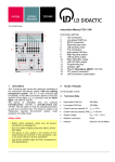
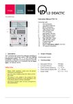
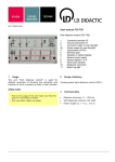
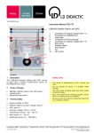
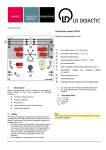
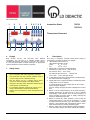
Instruction Sheet 725 721 8 9 10 11 12 13 14 15 16 3 Button for selection of AC (1) or three-phase voltage (3). In the single-phase operation, voltage is only applied between U and N; in the three-phase operation, sockets U, V and W are active. LED indicates the selected operating mode. If this button is held pressed during power on, the maximum line voltage in 3~ mode is increased to 41 V. Button to change the phase sequence for selecting the field rotation direction, LED indicates the rotation direction. Illuminated power switch. Rotary encoder for adjusting the frequency or position of the field set with the “Stepˮ button (6). A clockwise turn increases the value, while a counterclockwise turn reduces it: 0.01 – 0.09 Hz in 0.01 Hz steps 0.1 – 0.9 Hz in 0.1 Hz steps 1 – 9.5 Hz in 0.5 Hz steps 10 – 99 Hz in 1 Hz steps 100 – 500 Hz in 5 Hz steps Safety sockets for three-phase or AC voltage. In AC operation mode, a maximum of 24 V can be drawn between N and the phase conductor U. In 3~ mode, 24 V or 41 V can be obtained between the phase conductors U-V-W (see point 8) and 14 V or 24 V between the phase conductor and N respectively. The outputs are short-circuit-proof. Rotary encoder for setting the AC voltage. Turning clockwise increases the value, turning counterclockwise reduces it. Pressing wheel inward against the front panel toggles voltage on and off, with state indicated by LED. 6-pin DIN socket for the rotor position sensor 727 812. If connected, “BLDCˮ mode is automatically activated. LED activated when rotor position sensor is connected. The rotor position sensor only works with the ELM magnet rotor 563 19 or ELM 4 pole magnet rotor 563 191 manufactured after May 2012. In BLDC mode, buttons 5-9 are deactivated. Rotary encoder for setting the DC voltage. A clockwise turn increases voltage, while turning counterclockwise reduces it. Pressing the wheel inward against the front panel toggles the voltage on and off. LED indicates the on/off state. Safety sockets provide a maximum DC voltage of 15 V. Positive is applied to the red socket, negative is applied to the blue socket. The outputs are short-circuit-proof. Page 2/2 4 Technical data 3 HU rack panel equipped with illuminated power switch Output voltage AC 0…24 V Output voltage 3~ 3 x 0…24 V/41 V Output voltage DC 0…15 V All outputs are short-circuit-proof. Voltage generation: Sine or block commutated pulse width modulation Output current 1.5 A Output frequency 10 mHz to 500 Hz, adjustable Intermediate circuit voltage 96 V= Outputs 6 x 4 mm safety sockets Mains connection 725721: 5-pin connector system with leading protective contact, wired and ready for connection 725721G IEC socket C13 Width: 56 DU (depth units) Usage The electronic three-phase generator 725 721 or 725 721G enables the generation of variable frequency and variable amplitude small AC voltages and three-phase AC voltages by means of PWM and DC voltages. Two different waveforms are available to simultaneously perform experiments in AC and three-phase fields. The electronic three-phase generator is used for powering Electric Training Machines (ELM) in the geared towards Electrical Engineering and Automotive Technology A 2.7.2.2. Here it is meant for powering three-phase, AC and DC machines including the linear motor. LD DIDACTIC GMBH Leyboldstrasse 1 D-50354 Hürth Phone (02233) 604-0 Fax (02233) 604-222 e-mail: [email protected] by LD Didactic GmbH Printed in the Federal Republic of Germany Technical alterations reserved