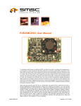
1
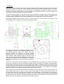
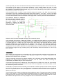
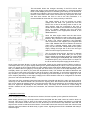
User's Manual for “teba“ Solar T-62T-32 ECU
(Firmware Revision 1.5)
1. Basic Features of the ECU:
➔ specifically designed for the Solar T-62T-32 turbine engines
➔ controls all the engine systems and monitors their functions
➔ includes analogue governor (RPM stability appr. +-0.5% no-load / full-load), startup sequencer,
safety monitoring systems
➔ internal data logging of the last 136 minutes of operation on a secondly schedule as well as total run
time and startup cycle counter, data can be retrieved by an USB 2.0 interface onto a PC
➔ post-shutdown status indicator to show the reason for a "red light" (if any) during engine operation
➔ optional 12V lead-acid chemistry back-up battery can be attached so the engine will be kept running
if main power fails, backup battery is recharged during normal operation
➔ operates from 12V to 28V, maximum current consumption during startup 25A, during normal
operation approx. 5A (12V operation)
➔ internal, electronic RPM preset pot to eliminate long, RFI-sensitive and safety-critical wires as well
as failure-prone mechanical pots
➔ control panel is equipped with three back-lit LCDs to show preset RPM percentage, actual engine
RPM percentage and EGT in degrees centigrade (can be modified to display fahrenheit), one
momentary "start engine" switch and an ultrabright two-colour LED indicator to indicate engine status
➔ connections for rpm trim up, rpm trim down and "kill engine" momentary switches
➔ up to four auxiliary inputs for pressure or temperature switches or chip detectors
➔ two auxiliary digital/analogue inputs/outputs to interface to optional switch box or sensors
➔ RFI insensitive optocouplers on all digital external connections (including USB)
➔ hermetically sealed aluminium enclosure, Amphenol/Cannon MIL style connector, sealed industrial
USB connector
➔ ECU is pre-adjusted to work directly, without additional adjustment, on any stock T-62T-32 engine
with an aftermarket 12V starter (original starters will also work if 24V power system or external 24V
supply is used)
➔ ECU firmware is user-upgradable through the USB port by a boot loader running on a PC
2. Installation
The ECU is mounted in close proximity to the turbine engine, preferably at the right hand side of the gearbox
when looking at the exhaust. Four rubber damping elements are provided to isolate the ECU from highfrequency vibration of the engine or the mounting frame. The orientation of the ECU is arbitrary. Yet, it may
be useful to have the USB connector easily accessible for engine data download. If this isn't possible, an
USB extension lead with sealed connectors is available.
The main electrical connector to the engine and control accessories is a single, 35-pin Amphenol MIL style
connector, type M53106R32-7S, which is supplied with the ECU. The ground connection is established via
two M6 stud bolts. Suitable ring wire lugs are supplied. Don't overtighten the nuts on the stud bolts!
The following diagram shows the basic “minimum“ interconnection for a running system. For testing only, the
backup battery can be omitted. The master caution light is optional.
The ground connection is of essential importance. Since
the voltages at the EGT thermocouple terminals are just a
few millivolts while the body of the engine may carry
several hundreds of amperes of current, electric
interference is a sure thing if the instructions provided here
aren't followed. Most important thing to observe: Avoid
major ground loops! Connect the battery minus only to the
place where the highest current consumption is expected.
This is the mounting flange of the starter motor (see above
diagram).
The ECU is connected to the engine gearbox by two substantial wires of at least 4mm² cross-section (AWG
6) that are to be kept as short as reasonably possible (GND1 and GND2 are arbitrarily interchangeable).
Further system ground connections have to be referenced to GND1 or GND2 at the ECU enclosure. A stack
of multiple wire lugs may be used on these threaded bolts. Only very high current return lines should be
directly referenced to the starter mounting flange (like the ground return of an alternator for example).
NEVER rely solely on a metallic frame structure to close the ground circuit!
The main battery must be fused for all devices connected to it except the starter motor. It's a good practice to
place a high-current fuse (i.e. 100A) in close proximity to the battery as a fire protection device. Also try to
keep the positive wire from the battery to the starter as short as possible, use good quality wire and sleeve it
so it won't fray if it touches vibrating metallic surfaces. Thoroughly isolate the connections of the substantial
positive wires so they cannot be touched accidentally with tools or other instruments. Always disconnect the
NEGATIVE of the main battery when working on the electrical system.
The backup battery is of the 12V lead-acid chemistry and should be able to provide a current of at least 10A.
The capacity of this battery is of secondary importance. A 5Ah lead-gel battery (as used for small
uninterruptable power supplies) should do. Since the backup battery is a safety-critical component, it should
be considered a consumable and be replaced every year. A check of the backup power system is mandatory
and should be included in the check-list.
In the schematic shown, a switch is used to directly supply main power to the ECU. Since the current
consumption of the ECU is substantial (especially during engine startup) – up to 25A –, it may not be viable
to use a (key) switch directly for this purpose. The following schematic shows a method to use a power relay
to remove the substantial currents for the Main Power (key) switch. The relay should be rated at least 60A.
The schematic features an additional
advantage by incorporating the diode D1
as a reverse polarity protection device. If
the main battery is accidentally
connected in reverse, the diode will
block and the relay will not close the
circuit to the ECU.
Otherwise, the ECU will be damaged if the supply is connected in reverse.
In the schematic shown above, an alternator is added -- we modified the Solar gearbox to accommodate the
alternator opposite to the starter. The Alternator we used is a Nippon Denso, model 31400-75F0 / F5, found
in a Suzuki Wagon R+ 1.0l 48kW. The color-scheme of the wires refers to that particular alternator. Another
interesting detail shown in the schematic is the utilization of the start fuel valve signal to activate the
alternator only after the engine transitions from “acceleration“ to “run“ mode by using a normally closed relay
configuration. Yet, the optional “Switch Box“ is a more elegant way to control an alternator since this will take
into account the engine load (by monitoring EGT) and momentarily disable the alternator in case of high
power demand.
3. Accessories
Upon inquiries of some customers, we decided to offer (so far) two optional extension boxes to interface the
ECU to third-party equipment such as an EFIS type glass cockpit, an air condition compressor or an
alternator with extended control capabilities.
These two extension boxes are the “Isolation Amplifier“ (IA) to eliminate ground voltage differentials when
interfacing the analog engine parameters to an EFIS, and the “Switch Box“ (SB), containing two
independently controllable relays in SPOC configuration.
The IA features an adjustment to calibrate the values displayed on the EFIS and to match the output voltage
to the input voltage range of the particular EFIS model. The IA is independent of the ECU firmware and can
be used with any version of the ECU.
The SB will be connected to the two auxiliary in/out channels of the ECU (X106) and also receives its power
from the ECU. The firmware needs to be adapted to the particular functions required by the customer and
has to be negotiated upon for every new application. A customized firmware version will be supplied for
flashing into the ECU.
The connectors of the accessory modules are spring-loaded wire clamps. The rated cross-section for flexible
wires is 1mm² (AWG 17). The wires should be stripped about 8mm long, twisted and tinned. Then they are
just pushed into the connector as far as they will go. To remove them, push in the orange tab with a small,
flat screwdriver and pull out the wire. Only a single wire can be connected to each socket!
This schematic shows the changes necessary if the ECU will be used
without the engine control terminal and connected to a customer-supplied
EFIS or other display terminal. To eliminate ground loops, the IA will have to
be used as an interface. The input section of the IA receives its power from
the ECU. These wires must not be connected to any other place. Since the
five lines that connect the ECU to the IA are RFI insensitive, it is
recommendable to locate the IA in close proximity of the EFIS.
The output section of the IA receives its supply
voltage from the EFIS. The ground wire from the
EFIS to the IA has to be solely used for the IA. No
other devices must be connected to this wire. If
another device needs to be referenced to this ground
point, run another, separate wire from the EFIS
ground terminal to the appropriate terminal of the
additional device.
Since the start engine switch and the dual colour
engine status indicator are part of the engine control
terminal, they will have to be connected separately
as shown. The colours specified in the schematic
refer to the wires of the supplied, pre-configured dual
colour LED. Parallel with the red element of the dual
colour LED, a “Master Caution Light“ (aka “Devil's
Eye“) may be connected. Independent of the system
supply voltage, this light has to be of the 24V type
and must not be higher power than 12W.
The IA includes three 20-turn trimmers to calibrate
the instruments of the EFIS. After you set up the
EFIS to display three analog gauges for preset RPM
(PRS), actual engine RPM (RPM) and exhaust gas
temperature (EGT), only connect X103 Y to input A of
the IA as well as the power supply (X103 W and a).
So far, leave the inputs B and C of the IA unconnected. Power up the system and trim RPM to maximum.
Then adjust Gain A so you get a display reading for the preset RPM (PRS) of 102.5%. Now connect the wire
X103 Y to input B of the IA. Adjust Gain B to get a reading of the actual engine RPM gauge of 100.0%. After
that, you calibrate the EGT gauge by moving the wire from X103 Y to input C of the IA and adjusting Gain C
to display 1000°C (or 1832F if you prefer this temperature scale). This finalizes the IA/EFIS calibration and
you can connect the wires to the inputs of the IA as shown in the schematic. If you find the adjustment to be
very sensitive, you may have selected a too high sensitivity of the EFIS inputs. The IA can supply up to 12V
at the outputs (depending on the supply voltage) so the EFIS wouldn't need to be configured too sensitive
(five to ten volt full-scale would be ideal).
The lower part of the schematic shows the interconnection of the SB with the ECU. Again, the wires must be
used only for the SB and shouldn't be connected to anything else. Also these lines are RFI insensitive so
they can be kept at an arbitrary length. The interconnection with the accessories to be controlled via the SB
has to be figured out depending on the particular set-up. The relays in the SB have a contact rating of
24VDC / 250VAC at 16A. Yet, due to the connectors, the maximum continuous current should be limited to
10A.
4. Operation of the ECU
Once everything is installed, checked and re-checked, it's time to power up the system for the first time.
When initially powering up, the torque motor will be energized with the rated current of 0.5A for about 1.5
seconds. This can be used to check if the return spring of the throttle actuating mechanism is configured
correctly. The throttle control lever has to move all the way to the maximum stop setscrew. After that, the
torque motor current is reduced to the minimum. The throttle control lever must now touch the minimum stop
setscrew. Now the indicator will blink slowly in green colour, signaling that the ECU is initialized and ready to
start the engine.
Before actually starting the engine for the first time, it is a good idea to check that the EGT thermocouple is
connected properly. Point a torch or a heat gun at the tip of the thermocouple and observe that the EGT
gauge actually shows an increase in temperature. If it doesn't, reverse the polarity at the thermocouple
terminals.
The analog RPM measuring circuitry of the ECU that also provides the signal for the RPM gauge is only
working properly if there's an input frequency present at the RPM pickup terminals. If the engine is at rest,
the RPM value may droop. This is not a fault and will automatically reset upon the first revolution of the
engine.
Please also make sure that the engine has got a good supply of fuel and that the fuel system is primed (i.e.
with the main fuel cock open and the fuel boost pump energized, carefully loosen the fuel inlet fitting at the
FCU a tiny bit until fuel starts to weep from it). Also check the oil level and tip up if necessary. Make sure that
both the compressor intake and the turbine exhaust aren't obstructed and that there's no loose material
nearby that can be sucked in or blown over.
After the system is prepared so far, a cold crank should be attempted. To do this, momentary press the
“Engine Shutdown” button. The slow green flashing of the indicator will go solid green. In this configuration,
upon the next start cycle, neither the ignition exciter nor the main or start fuel valves will be opened. This is
useful for blowing out excessive fuel or fuel vapor after a failed start or for priming the lubrication system
after an oil change or a long period of rest of the engine. Make sure that the engine reaches at least 15%
RPM. If it won't, check (and recharge) the battery and the starter. Don't cold crank the engine too long since
it highly stresses the starter and the battery and allow the starter to cool for several minutes before
attempting another cold crank or start. If not done by the operator before, the cold crank cycle will be
terminated by the ECU after 30 seconds. Since the engine has not reached self-sustain, the indicator will
always flash an error code (either 6 flashes, indicating that the startup attempt took longer than 30 seconds –
if the ECU terminated the cycle – or 7 flashes, indicating that the startup button has been released before
self sustain speed was reached). The system can be returned to the “ready to start mode” by momentarily
pressing the start button.
Now that all systems have been checked successfully, it's time for the first real engine start. Press and hold
the engine start button until the engine exceeds approx. 35% RPM and the fast flashing of the green
indicator will go solid. The engine should smoothly accelerate to preconfigured idle RPM and stabilize
(around) there. If the engine continues to accelerate, immediately shut it down and unscrew the minimum
stop setscrew at the FCU by half a turn. With the ECU powered up and idle, make sure the throttle control
lever is actually touching the minimum stop setscrew. If it is not, you may readjust the return spring at the
torque motor lever a little to arrange this. Then reattempt a start.
If the engine idles satisfactorily, have a close look at the position of the throttle control lever and check that
the distance between the minimum stop setscrew and the lever is approximately equivalent to a quarter turn
of the setscrew. Otherwise, correct this. If you manually move the lever to the minimum stop, the engine
should slowly decelerate but not flame out. If you release the lever again, the engine should immediately
accelerate back to idle.
NEVER Manipulate The Throttle Control Lever With The Engine Running Above 65% RPM!
You may cause a dangerous runaway situation since the engine will accelerate more aggressively the higher
it revolves. The ECU will shut down the engine in case of a severe overspeed but if for instance an NO
modified main fuel valve is being used and the connector was pulled, or electric power is lost, all the safety
systems are bypassed. The engine will self-destruct between 120 and 130% RPM.
At idle without any mechanical load, EGT should read between 300C and 350C, depending on ambient
temparatures. Now you can trim up engine RPM. At around 80% (or whatever acceleration → run mode
transition speed had been configured), you may notice a slight RPM instability and a slight tendency to
hunting that should even out within a second. It should be possible to smoothly trim up the engine to 100%
and (only with a further five manual increments) to 102.5%. If you notice hunting tendencies, the FCU may
not be properly adjusted or the friction washers on top of the FCU's throttle control shaft may not be installed
or not properly pre-tensioned. To correct this is a delicate thing and it should be done by somebody who's
experienced with the engine. When trimming down the RPM too quickly, the engine may flame out between
70 and 50% RPM which is a result of the FCU having never been designed for this kind of operation. If it is
desirable to trim down back to idle completely automatically, a firmware version with a slow auto decrement
is available upon request. At 100% RPM no load, the EGT will read 340C on a good engine.
Shut down the engine by pressing and holding the “Shutdown” button for at least half a second. Don't turn off
the electrical systems before the engine came to a complete rest.
Appendix 1 – The operation of the ECU in detail
When the ECU is powered up, the main fuel valve is closed and the torque motor is supplied with the full
drive current (0.5A) for slightly less than two seconds. That's actually the time the ECU is being reset and
waits for the bootloader program to establish communication. If the bootloader master is not found, normal
operation (governor/sequencer mode or data communication mode if the stop switch is being pressed during
power-up) commences. The 0.5A current to the torque motor permits to check the proper movement
range/power of the fuel metering system.
Now here's the sequence that is processed during engine start-up:
1.
2.
3.
4.
5.
6.
7.
The engine operator presses and holds the "Start Engine" button
The ECU checks the battery voltage (has to be more than 12V while the starter is not running).
The Master Caution Light (Devil's Eye) is illuminated for two seconds to permit to check it's working
The digital "throttle preset pot" is initialized to idle RPM
The governor ciruitry of the ECU is enabled and reset
The starter motor is energized
Now the system checks if the startup cycle is commanded as a "real" start or just a cold crank cycle, in
which case the following steps except for the starter time limit check are skipped.
8. The backup supply is switched on.
9. At 2% engine RPM, the ignition exciter is energized
10. At 4% RPM the start fuel valve is opened
11. At 15% RPM the EGT is checked to be at least 100C (212F). If this is found true, the main fuel valve is
opened. The start fuel valve will stay energized at that time, so the engine accelerates on both start fuel
and main fuel (the latter routed through the acceleration limiting valve by the energized start fuel valve).
12. At 35% RPM the engine is able to self-sustain and the starter and ignition exciter are deenergized. The
start fuel valve still stays energized to allow smooth acceleration. The startup cycle is completed and the
system switches over to "acceleration mode". The green indicator stops flashing and goes solid. The
startup cycle counter in the engine logs is incremented. The "Start Engine" button can be released.
At the same time, the following parameters are monitored to identify a malfunction and to prevent the engine
from being damaged:
13.
14.
15.
16.
17.
If the "Start Engine" button is released before step 12, the startup cycle is immediately terminated.
If the start cycle takes longer than 30 seconds, it is terminated to prevent the starter from overheating.
If at 30% engine RPM no oil pressure is indicated, the startup cycle is terminated.
If EGT exceeds 600C (1112F), the startup cycle is terminated.
If the ECU finds an internal control flag set that checks for faulty code execution in the microprocessor,
the startup cycle is terminated.
The fault conditions can be identified by an unique flash pattern of the "Devil's Eye" or by downloading and
checking the engine logs, see Appendix 2 for details.
Acceleration mode:
18. The engine accelerates to preset idle RPM and stays governed there (provided the mechanical
minimum fuel flow adjustment at the FCU matches the electronic idle RPM setting. Up to this speed, the
governor will keep the throttle valve fully open (i.e. at the maximum stop setscrew).
19. The RPM can now be trimmed up and down by inputs to the trim switches. There is an "auto
increment/decrement" function available that continues to increase/decrease preset RPM if the
corresponding switch is pressed longer than one second.
20. The RPM trim up function is momentarily inhibited if the actual engine RPM is more than 3.5% below the
preset RPM.
21. The RPM trim up function is also momentarily inhibited if EGT reaches 600C. The indicator will be lit
orange and the "Devil's Eye" will turn on.
22. If EGT increases further (between 625C and 650C), RPM preset will be automatically decremented.
23. If EGT exceeds 650C, the engine will be shut down.
24. If no oil pressure is signaled to the ECU for longer than one second, the engine will be shut down.
25. If no oil pressure is signaled to the ECU for less than one second, the indicator will be lit orange and the
"Devil's Eye" will turn on. If oil pressure returns within this period, normal engine operation will be
resumed.
26. If the main power supply voltage drops below 9V, the indicator will be lit orange and the "Devil's Eye" will
turn on.
27. If the ECU finds an internal control flag set that checks for faulty code execution in the microprocessor,
the engine will be shut down.
28. If engine RPM exceeds the "run mode transition point" (standard is 80% or configured in firmware as
requested by the customer) by more than 5%, the engine will be shut down.
29. The "auto increment" function will terminate at the "run mode transition point" and the ECU will wait for
actual engine RPM to reach that RPM by a margin of no more than one percent. If then "RPM Trim Up"
is pressed once, the ECU deenergizes the start fuel valve and switches over to "run mode".
Run Mode:
30. In "run mode", the acceleration limiter valve in the FCU is bypassed and the acceleration can be quite
violent if preset RPM is increased too quickly.
31. The engine protection features of "start mode" and "acceleration mode" are disabled and only warnings
are issued via the "Devil's Eye" if a possible problematic engine condition is identified. It's the pilot's
decision to take corrective action.
32. There's one situation that is indicative for an automatic engine shutdown and that's either a faulty engine
RPM signal or an engine RPM reading more than 110%. If either of this failure occurs, the engine
cannot be governed anymore and further operation is a bigger hazard than a forced landing.
33. The "auto increment" will permit to accelerate the engine up to 100% rpm. Manually, the RPM can be
trimmed up to 102.5% if the situation requires that.
34. If actual RPM drops more than 5% below preset RPM and an EGT less than 450C is recorded, the
ECU "assumes" a flameout and will attempt a relight which can take several seconds, requires the
engine to be unloaded and may even be not successful. The procedure in detail is quite complex and
isn't essential for understanding the engine operation. It is sufficient to know that after a successful
relight, the engine will be accelerated back to the RPM where the flameout occurred.
Shutdown:
35. The shutdown button has to be pressed longer than 0.5 seconds in order to have an effect.
36. If during normal operation the shutdown signal is active for less than 0.5 seconds continuously, the ECU
will log a "Shutdown Signal Error" and display a warning after shutdown to indicate a possible electrical
problem with the shutdown line.
37. If the shutdown has been successfully commanded, the main fuel valve is closed, the governor is shut
down and RPM is monitored while the engine coasts to a halt. The time the engine rotor needs to coast
from 35% to a complete stop is logged and compared to the previous coast-down time. If there's a
difference of more than five seconds, a warning code is flashed. In this case, the situation should be
further analyzed (by downloading the logs and comparing the conditions).
38. Only after the engine rotor has come to a complete stop, the engine log record is closed, the coastdown
time written and then the backup power supply is cut. This means, even if the main power is removed
from the engine before, the records will be closed in a "clean" manner and – if the engine has been
converted to a “NO“ main fuel valve configuration - the main fuel valve will stay closed until the fuel
pump stopped turning, preventing smoke or a torching turbine.
Appendix 2 – Error codes
The code will be flashed with the red LED and the “Devil's Eye“ (if connected). There will be a number of
flashes displayed after engine shutdown in quick sequence, followed by a pause.
Count / Colour
of flashes
Description / Countermeasures
Infinite / Green normal manual shutdown, no errors
1 / Red
no oil pressure signal present for longer than one second
2 / Red
EGT extremely high (beyond 650°C)
3 / Red
relight attempt not successful
4 / Red
engine RPM went below 35% (if this occurs during acceleration phase, check clutch)
5 / Red
engine speed has exceeded 110% and as a consequence has been shut down by the ECU
6 / Red
startup attempt took longer than 30 seconds and has been terminated by the ECU
7 / Red
start button has been released before the engine reached self-sustain speed
8 / Red
battery voltage less than 12V before engine startup
9 / Red
intermittent signals on the "kill engine" line - check wiring / kill switch
10 / Red
engine coast down time 35% -> 0% differs more than 5 seconds from last time - check
engine oil / bearings
Infinite / Red
An error in execution of the firmware has been detected, have the ECU checked / replaced
Warning conditions during engine operation:
Indicated by a Momentary orange LED and an illuminated “Devil's EYE“ (if installed), which are
– momentary high EGT (between 620°C and 650°C)
– momentary low oil pressure indication of less than one second duration
These limiting situations are considered acceptable if they don't persist for a substantial time or occur
repeatedly. They are meant as a warning signal to catch the engine operator's attention before actually a
dangerous situation evolves.
If these conditions are exceeded or persist longer than specified, or other serious malfunctions in the power
plant system are detected, the ECU will take preventive measures, depending on its current operation mode.
During engine startup or acceleration, the engine will be shut down by the ECU since
this won't be safety-critical.
During run mode, the engine won't be shut down except there's a severe overspeed. Instead, the LED
indicator will be lit red permanently, indicating that there is a serious problem and continued operation of the
engine may not be safe anymore.