1
EPPCBug
Firmware Package
User’s Manual
Version 1.1
EPPCBUGA1/UM1
Notice
While reasonable efforts have been made to assure the accuracy of this document,
Motorola, Inc. assumes no liability resulting from any omissions in this document,
or from the use of the information obtained therein. Motorola reserves the right to
revise this document and to make changes from time to time in the content hereof
without obligation of Motorola to notify any person of such revision or changes.
No part of this material may be reproduced or copied in any tangible medium, or
stored in a retrieval system, or transmitted in any form, or by any means, radio,
electronic, mechanical, photocopying, recording or facsimile, or otherwise,
without the prior written permission of Motorola, Inc.
It is possible that this publication may contain reference to, or information about
Motorola products (machines and programs), programming, or services that are
not announced in your country. Such references or information must not be
construed to mean that Motorola intends to announce such Motorola products,
programming, or services in your country.
Restricted Rights Legend
If the documentation contained herein is supplied, directly or indirectly, to the U.S.
Government, the following notice shall apply unless otherwise agreed to in
writing by Motorola, Inc.
Use, duplication, or disclosure by the Government is subject to restrictions as set
forth in subparagraph (c)(1)(ii) of the Rights in Technical Data and Computer
Software clause at DFARS 252.227-7013.
Motorola, Inc.
Computer Group
2900 South Diablo Way
Tempe, Arizona 85282
Preface
The EPPCBug Firmware Package UserÕs Manual provides information on the EPPCBug
Þrmware, the start-up and boot routines, the debugger commands, the one-line assembler/
disassembler, and the debugger system calls. All information contained herein is speciÞc to
MotorolaÕs PowerPCª-based MBX Series boards.
This manual covers release 1.1 of EPPC1Bug.
Motorola¨ and the Motorola symbol are registered trademarks of Motorola, Inc.
PowerStack is a trademark of Motorola, Inc.
PowerPCª is a trademark of IBM, and is used by Motorola with permission.
AIXTM is a trademark of IBM Corp.
SunOSª is a trademark of Sun Microsystems.
Windows¨ is a registered trademark of Microsoft Corp.
All other products mentioned in this document are trademarks or registered
trademarks of their respective holders.
Safety Summary
Safety Depends On You
The following general safety precautions must be observed during all phases of operation, service, and
repair of this equipment. Failure to comply with these precautions or with speciÞc warnings elsewhere in
this manual violates safety standards of design, manufacture, and intended use of the equipment.
Motorola, Inc. assumes no liability for the customer's failure to comply with these requirements.
The safety precautions listed below represent warnings of certain dangers of which Motorola is aware. You,
as the user of the product, should follow these warnings and all other safety precautions necessary for the
safe operation of the equipment in your operating environment.
Ground the Instrument.
To minimize shock hazard, the equipment chassis and enclosure must be connected to an electrical ground.
The equipment is supplied with a three-conductor ac power cable. The power cable must be plugged into
an approved three-contact electrical outlet. The power jack and mating plug of the power cable meet
International Electrotechnical Commission (IEC) safety standards.
Do Not Operate in an Explosive Atmosphere.
Do not operate the equipment in the presence of ßammable gases or fumes. Operation of any electrical
equipment in such an environment constitutes a deÞnite safety hazard.
Keep Away From Live Circuits.
Operating personnel must not remove equipment covers. Only Factory Authorized Service Personnel or
other qualiÞed maintenance personnel may remove equipment covers for internal subassembly or
component replacement or any internal adjustment. Do not replace components with power cable
connected. Under certain conditions, dangerous voltages may exist even with the power cable removed. To
avoid injuries, always disconnect power and discharge circuits before touching them.
Do Not Service or Adjust Alone.
Do not attempt internal service or adjustment unless another person capable of rendering Þrst aid and
resuscitation is present.
Use Caution When Exposing or Handling the CRT.
Breakage of the Cathode-Ray Tube (CRT) causes a high-velocity scattering of glass fragments (implosion).
To prevent CRT implosion, avoid rough handling or jarring of the equipment. Handling of the CRT should
be done only by qualiÞed maintenance personnel using approved safety mask and gloves.
Do Not Substitute Parts or Modify Equipment.
Because of the danger of introducing additional hazards, do not install substitute parts or perform any
unauthorized modiÞcation of the equipment. Contact your local Motorola representative for service and
repair to ensure that safety features are maintained.
Dangerous Procedure Warnings.
Warnings, such as the example below, precede potentially dangerous procedures throughout this manual.
Instructions contained in the warnings must be followed. You should also employ all other safety
precautions which you deem necessary for the operation of the equipment in your operating environment.
!
WARNING
Dangerous voltages, capable of causing death, are present in this
equipment. Use extreme caution when handling, testing, and
adjusting.
The computer programs stored in the Read Only Memory of this device contain
material copyrighted by Motorola Inc., 1997, and may be used only under a license
such as those contained in MotorolaÕs software licenses.
The software described herein and the documentation appearing herein are
furnished under a license agreement and may be used and/or disclosed only in
accordance with the terms of the agreement.
The software and documentation are copyrighted materials. Making unauthorized
copies is prohibited by law. No part of the software or documentation may be
reproduced, transmitted, transcribed, stored in a retrieval system, or translated
into any language or computer language, in any form or by any means without the
prior written permission of Motorola, Inc.
Disclaimer of Warranty
Unless otherwise provided by written agreement with Motorola, Inc., the software
and the documentation are provided on an Òas isÓ basis and without warranty.
This disclaimer of warranty is in lieu of all warranties whether express, implied, or
statutory, including implied warranties of merchantability or Þtness for any
particular purpose.
!
WARNING
This equipment generates, uses, and can radiate electromagnetic energy. It may cause or be susceptible to electromagnetic interference (EMI) if not installed and used in a
cabinet with adequate EMI protection.
© Copyright Motorola, Inc. 1997
All Rights Reserved
Printed in the United States of America
June 1997
Contents
Introduction 1-1
Typographic Conventions 1-2
Terminology Conventions 1-3
Related Documentation 1-4
Product Structure 2-1
Firmware (Debugger) Overview 2-3
Description of EPPCBug 2-3
Comparison with other Motorola Firmware 2-4
EPPCBug Implementation 2-5
General Installation and Startup 2-6
Hardware Initialization 2-7
Restarting the System 2-9
Reset 2-9
Break 2-9
Diagnostic Facilities 2-11
Memory Requirements 2-11
I/O and Memory Address Map 2-12
Terminal Input/Output Control 2-15
How to Enter Debugger Command Lines 3-1
Control Characters 3-2
Syntactic Variables 3-3
Expression as a Parameter 3-4
Address as a Parameter 3-5
Address Formats 3-5
Offset Registers 3-6
Port Numbers 3-7
EPPCBug Port Numbers 3-7
How to Enter and Debug Programs 3-7
Call System Utilities from User Programs 3-8
Preserve the Debugger Operating Environment 3-8
EPPCBug Vector Table and Workspace 3-8
Hardware Functions 3-9
Exception Vectors Used by EPPCBug 3-9
MPU/CPU Registers 3-10
MPU Register SPR272 3-10
MPU Registers SPR273-SPR275 3-10
Context Switching 3-10
Floating Point Support 3-11
Single Precision Real 3-12
Double Precision Real 3-12
ScientiÞc Notation 3-13
Command Descriptions 4-1
AS - One Line Assembler 4-4
Command Input 4-4
Description 4-4
BC - Block of Memory Compare 4-5
Command Input 4-5
Options 4-5
Description 4-5
Examples 4-5
BF - Block of Memory Fill 4-7
Command Input 4-7
Options 4-7
Description 4-7
Examples 4-8
BI - Block of Memory Initialize 4-10
Command Input 4-10
Options 4-10
Description 4-10
Examples 4-10
BM - Block of Memory Move 4-12
Command Input 4-12
Options 4-12
Description 4-12
Examples 4-12
BR - Breakpoint Insert/Delete 4-15
Command Input 4-15
Description 4-15
Examples 4-15
BS - Block of Memory Search 4-17
Command Input 4-17
Options 4-17
Description 4-17
Examples 4-19
BV - Block of Memory Verify 4-22
Command Input 4-22
Options 4-22
Description 4-22
Examples 4-23
CS - Checksum a Block of Data 4-25
Command Input 4-25
Options 4-25
Description 4-25
CSAR - PCI ConÞguration Space READ Access 4-27
Command Input 4-27
Options 4-27
Description 4-27
Example 4-27
CSAW - PCI ConÞguration Space WRITE Access 4-28
Command Input 4-28
Options 4-28
Description 4-28
Example 4-28
DC - Data Conversion 4-29
Command Input 4-29
Options 4-29
Description 4-29
Examples 4-29
DS - One Line Disassembler 4-31
Command Input 4-31
Description 4-31
DTT - Display Temperature 4-32
Command Input 4-32
Description 4-32
Example 4-32
DU - Dump S-Records 4-33
Command Input 4-33
Description 4-33
Examples 4-34
ECHO - Echo String 4-35
Command Input 4-35
Description 4-35
Examples 4-35
ENV - Edit Environment 4-37
Command Input 4-37
ENV Command Parameters 4-38
GD - Go Direct (Ignore Breakpoints) 4-41
Command Input 4-41
Description 4-41
Examples 4-41
GN - Go to Next Instruction 4-43
Command Input 4-43
Description 4-43
Examples 4-43
GO - Go Execute User Program 4-45
Command Input 4-45
Description 4-45
Examples 4-45
GT - Go to Temporary Breakpoint 4-48
Description 4-48
Examples 4-48
HBD - History Buffer Display 4-51
Command Input 4-51
Description 4-51
Examples 4-51
HBX - History Buffer Entry-Execute 4-52
Command Input 4-52
Description 4-52
Examples 4-52
HE - Help 4-53
Command Input 4-53
Description 4-53
Examples 4-53
I2C - I2C Device Read/Write 4-56
Command Input 4-56
Arguments 4-56
Options 4-56
Description 4-56
Examples 4-56
IOC - I/O Control for Disk 4-58
Command Input 4-58
Description 4-58
IOI - I/O Inquiry 4-60
Command Input 4-60
Options 4-60
Description 4-60
IOP - I/O Physical to Disk 4-62
Command Input 4-62
Description 4-62
IOT - I/O ÒTeachÓ for ConÞguring Disk Controller 4-66
Command Input 4-66
Options 4-66
Description 4-66
Attribute Parameters 4-69
LO - Load S-Records from Host 4-73
Command Input 4-73
Description 4-73
Examples 4-75
MA/NOMA - Macro DeÞne/Display/Delete 4-78
Command Input 4-78
Description 4-78
Examples 4-79
MAE - Macro Edit 4-82
Command Input 4-82
Options 4-82
Description 4-82
Examples 4-83
MAL/NOMAL - Enable/Disable Macro Expansion Listing 4-84
Command Input 4-84
Description 4-84
MD - Memory Display 4-85
Command Input 4-85
Options 4-85
Examples 4-86
MM - Memory Modify 4-89
Command Input 4-89
Options 4-89
Description 4-89
Examples 4-90
MMAP - Memory Map Display 4-93
Command Input 4-93
Description 4-93
Examples 4-93
MMD - Memory Map Diagnostic 4-95
Command Input 4-95
Options 4-95
Description 4-95
Examples 4-95
MS - Memory Set 4-97
Command Input 4-97
Description 4-97
Examples 4-97
MW - Memory Write 4-98
Command Input 4-98
Options 4-98
Description 4-98
Examples 4-98
NIOC - Network I/O Control 4-100
Command Input 4-100
Description 4-100
NIOP - Network I/O Physical 4-102
Command Input 4-102
Description 4-102
NIOT - I/O ÒTeachÓ for ConÞguring Network Controller 4-105
Command Input 4-105
Options 4-105
Description 4-105
NPING - Network Ping 4-110
Command Input 4-110
Arguments 4-110
Description 4-110
OF - Offset Registers Display/Modify 4-112
Command Input 4-112
Command Use 4-112
Description 4-112
Offset Register Rules 4-113
Examples 4-114
PA/NOPA - Printer Attach/Detach 4-115
Command Input 4-115
Description 4-115
Examples 4-115
PF /NOPF - Port Format/Detach 4-117
Command Input 4-117
Description 4-117
Listing Current Port Assignments 4-118
Examples 4-118
Configuring a Port 4-118
Examples 4-119
PFLASH - Program FLASH Memory 4-122
Command Input 4-122
Arguments 4-122
Options 4-122
Description 4-123
PL - Program Load 4-125
Command Input 4-125
Arguments: 4-125
Description 4-126
Examples 4-128
RD - Register Display 4-130
Command Input 4-130
Arguments 4-130
Description 4-130
Examples 4-132
RESET - Cold/Warm Reset 4-135
Command Input 4-135
Description 4-135
Examples 4-135
RL - Read Loop 4-137
Command Input 4-137
Options 4-137
Description 4-137
RM - Register Modify 4-138
Command Input 4-138
Description 4-138
Examples 4-138
RS - Register Set 4-140
Command Input 4-140
Description 4-140
Examples 4-140
SD - Switch Directories 4-141
Command Input 4-141
Description 4-141
Examples 4-141
SET - Set Time and Date 4-142
Command Input 4-142
Description 4-142
Examples 4-142
SYM - Symbol Table Attach 4-143
Command Input 4-143
Description 4-143
Examples 4-144
NOSYM - Symbol Table Detach 4-146
Command Input 4-146
Description 4-146
Example 4-146
SYMS - Symbol Table Display/Search 4-147
Command Input 4-147
Description 4-147
Examples 4-147
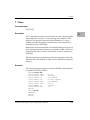
T - Trace 4-149
Command Input 4-149
Description 4-149
Examples 4-149
TA - Terminal Attach 4-153
Command Input 4-153
Description 4-153
Examples 4-153
TIME - Display Time and Date 4-154
Command Input 4-154
Description 4-154
Example 4-154
TM-Transparent Mode 4-155
Command Input 4-155
Description 4-155
Examples 4-156
TT-Trace to Temporary Breakpoint 4-157
Command Input 4-157
Description 4-157
Examples 4-157
UPM - MPC8xx User Programmable Machine (UPM) Display/Read/Write
4-160
Command Input 4-160
Arguments 4-160
Description 4-160
Example 4-160
VE - Verify S-Records Against Memory 4-162
Command Input 4-162
Options 4-162
Arguments 4-162
Description 4-163
Examples 4-164
VER - Revision/Version Display 4-167
Command Input 4-167
Description 4-167
Examples 4-167
VPD - (Vital Product Data) Display 4-169
Command Input 4-169
Description 4-169
Example 4-169
WL - Write Loop 4-170
Command Input 4-170
Options 4-170
Description 4-170
Overview 5-1
PowerPC Assembly Language 5-2
Machine-Instruction Operation Codes 5-2
Directives 5-2
Comparison with PowerPC Standard Assembler 5-3
Source Program Coding 5-4
Source Line Format 5-4
Operation Field 5-4
Operand Field 5-5
Disassembled Source Line 5-5
Mnemonics and Delimiters 5-6
Pseudo-Registers 5-6
Main Processor Registers 5-7
Character Set 5-9
Addressing Modes 5-10
The WORD DeÞne Constant Directive 5-12
The SYSCALL System Call Directive 5-12
How To Enter and Modify Source Programs 5-13
Invoke the Assembler/Disassembler 5-14
Enter a Source Line 5-15
How to Enter Branch Operands 5-16
Assembler Output/Program Listings 5-16
Assembler Error Messages 5-17
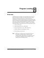
Overview 6-1
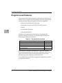
Program Load Features 6-2
Default Load Address Point (LAP) 6-3
Default Execution Address Point (EAO) 6-3
Default Intermediate Load Address Point (ILAP) 6-3
Additional Program Load Interfaces 6-3
Command Line Syntax 6-5
Automatic Program Load (AutoBoot) 6-5
Network 6-5
UDP/IP Protocol Modules 6-6
RARP/ARP Protocol Modules 6-7
BOOTP Protocol Module 6-7
TFTP Protocol Module 6-7
Network Boot Control Module 6-7
Mass Storage 6-8
Serial (SCC, SCM, SuperI/O) 6-8
PCMCIA (ATA/ROM/FLASH-Memory Cards) 6-8
FLASH Memory 6-9
ROM Boot 6-9
Disk File System (FAT) 6-9
File Formats 6-10
CDROM File System (ISO9660) 6-10
PowerPC ELF 6-10
S-Records 6-10
Command(s) Processor 6-10
Motorola ROM Boot 6-11
Register State at Program Load Time 6-12
Overview 7-1
How to Invoke System Calls 7-1
Input/Output Argument pointers 7-2
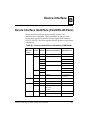
CLUN/DLUN Use by System Calls 7-3
System Call Routines 7-4
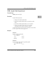
.CIO_READ 7-6
Description 7-6
Entry Conditions 7-6
Exit Conditions 7-7
.CIO_WRIT 7-8
Description 7-8
Entry Conditions 7-8
Exit Conditions 7-9
.CIO_STAT 7-10
Description 7-10
Entry Conditions 7-10
Exit Conditions 7-10
.CIO_CNFG 7-12
Description 7-12
Entry Conditions 7-12
Exit Conditions 7-13
.CIO_PUTS 7-14
Description 7-14
Entry Conditions 7-14
Exit Conditions 7-14
.CIO_GETS 7-15
Description 7-15
Entry Conditions 7-15
Exit Conditions 7-15
.MSIO_READ and .MSIO_WRIT 7-16
Description 7-16
Entry Conditions 7-16
Exit Conditions 7-17
.MSIO_CNFG 7-18
Description 7-18
Entry Conditions 7-18
Exit Conditions 7-18
Configuration Area Block CFGA Fields 7-22
.MSIO_CTRL 7-27
Description 7-27
Entry Conditions 7-27
Exit Conditions 7-28
.MSIO_FRMT 7-29
Description 7-29
Entry Conditions 7-29
Exit Conditions 7-30
.NIO_READ and .NIO_WRIT 7-31
Description 7-31
Entry Conditions 7-31
Exit Conditions 7-32
.NIO_CNFG 7-33
Description 7-33
Entry Conditions 7-33
Exit Conditions 7-33
.NIO_CTRL 7-38
Description 7-38
Entry Conditions 7-38
Exit Conditions 7-38
.RTC_READ 7-39
Description 7-39
Entry Conditions 7-39
Exit Conditions 7-39
.RTC_WRIT 7-40
Description 7-40
Entry Conditions 7-40
Exit Conditions 7-40
.FM_WRIT 7-41
Description 7-41
Entry Conditions 7-41
Exit Conditions 7-42
.SYMBOLTA 7-43
Description 7-43
Entry Conditions 7-43
Exit Conditions 7-43
.SYMBOLTD 7-45
Description 7-45
Entry Conditions 7-45
Exit Conditions 7-45
.RETURN 7-46
Description 7-46
Entry Conditions 7-46
Exit Conditions 7-46
.DELAY 7-47
Description 7-47
Entry Conditions 7-47
Exit Conditions 7-47
.BRDINFO 7-48
Description 7-48
Entry Conditions 7-48
Exit Conditions 7-48
.SCREV 7-50
Description 7-50
Entry Conditions 7-50
Exit Conditions 7-50
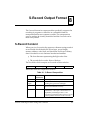
S-Record Content 8-1
S-Record Types 8-3
Creation of S-Records 8-5
Example 8-5
Overview A-1
Software Notes A-1
VPD Data Format A-2
VPD Data DeÞnitions A-3
Product ConÞguration Options Data A-5
FLASH Memory ConÞguration Data A-6
EEPROM Example A-6
C Header Files A-8
VPD.H A-8
DIMM.H A-10
SROM_CRC.C A-13
Device Interface IdentiÞers (CLUN/DLUN Pairs) B-1
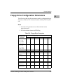
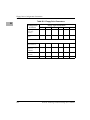
Floppy Drive ConÞguration Parameters B-3
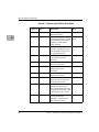
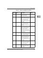
Overview D-1
History Buffer Commands D-1
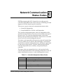
Introduction E-1
SCSI Firmware Status Codes E-2
1General Information
1
Introduction
This manual is intended for anyone who designs OEM systems,
supplies additional capability to an existing compatible system, or
works in a lab environment for experimental purposes.
A basic knowledge of computers and digital logic is assumed. Refer
to Related Documentation on page 1-4, of this manual for a list of
documents that may provide helpful information.
PowerPC EPPCBug Firmware Package UserÕs Manual
1-1
1
Typographic Conventions
Typographic Conventions
The following conventions are used in this document:
bold
Used for input that you type just as it appears. Bold is also
used for commands, options and arguments to
commands, and names of programs, directories, and Þles.
italic
Used for names of variables to which you assign values.
Italic is also used for comments in screen displays and
examples.
courier
Used for system output such as screen displays, reports,
examples, and system prompts.
RETURN
Represents the Enter, Return, or Carriage Return <CR>
key.
CTRL
Represents the Control key. Execute control characters by
pressing the CTRL key and the letter simultaneously, for
example, CTRL-d.
|
Separates two or more items that you can select from (one
only).
[]
Encloses an optional item that may occur zero or one time.
{}
Encloses an optional item that may occur zero or more
times.
1-2
PowerPC EPPCBug Firmware Package UserÕs Manual
General Information
Terminology Conventions
Throughout this manual, a convention has been maintained
whereby data and address parameters are preceded by a character
which speciÞes the numeric format as follows:
$
Dollar sign, speciÞes a hexadecimal character.
% Percent sign, speciÞes a binary number.
& Ampersand sign, speciÞes a decimal number.
Unless otherwise speciÞed, all address references are in
hexadecimal throughout this manual.
An asterisk (*) following the signal name for signals which are
level-signiÞcant denotes that the signal is true or valid when the
signal is low.
An asterisk (*) following the signal name for signals which are
edge-signiÞcant denotes that the actions initiated by that signal
occur on high to low transition.
In this manual, assertion and negation are used to specify forcing a
signal to a particular state. In particular
❏
Assertion and assert refer to a signal that is active or true
❏
Negation and negate indicate a signal that is inactive or false
These terms are used independently of the voltage level (high or
low) that they represent.
Throughout this manual, it is assumed that the MPU on the MBX is
programmed to big-endian byte ordering. Any attempt to use
little-endian byte ordering immediately renders the EPPCBug
debugger unusable.
PowerPC EPPCBug Firmware Package UserÕs Manual
1-3
1
1
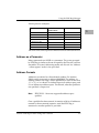
Related Documentation
Related Documentation
The following publications may provide additional helpful
information. If not shipped with this product, they may be
purchased by contacting your local Motorola sales ofÞce.
Document Title
Motorola Publication
Number
MBX Series Embedded Controller
Installation and Use
MBXA/IH
MBX Series ProgrammerÕs Guide
MBXA/PG
PowerPC Microprocessor Family:
The Programming Environments
MPCFPE/AD
DARPA Internet Request for Comments RFC-792
ISO-9660, Information processing - Volume and Þle structure of
CD-ROM for information interchange, International Organization for
Standardization.
System V Application Binary Interface, PowerPC Processor Supplement,
Sunsoft.
1-4
PowerPC EPPCBug Firmware Package UserÕs Manual
2Introduction to PowerPC
EPPCBug Firmware
2
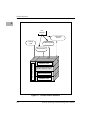
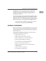
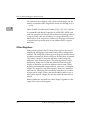
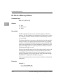
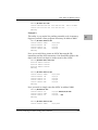
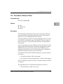
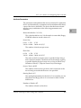
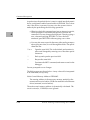
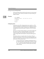
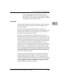
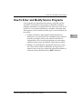
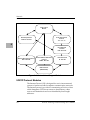
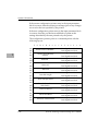
Product Structure
The overall product structure of the PowerPC EPPCBug Firmware
Package is the classic Operating System model. The devices and
hardware entities are abstracted via device and hardware drivers.
The user interfaces: remote, command, and programmatic, permit
you to access the devices and or hardware through a set of device
drivers. The kernel/monitor layer oversees all activities of the
product.
The hardware and Þrmware initialization attachment is responsible
for initialization of the hardware to enable a system boot. System
boot is the primary purpose of the Þrmware. System boot can be
viewed from loading a program for debugging purposes, to loading
an operating system which completely acquires control of the
hardware.
PowerPC EPPCBug Firmware Package UserÕs Manual
2-1
Product Structure
2
User
Interfaces
Programmatic
Interface
Powerup/
Reset
Command Interface
H/W & F/W INITIALIZATION
Remote Interface
INTERFACE LAYER
KERNEL (MONITOR) LAYER
DEVICE DRIVERS LAYER
HARDWARE LAYER
Figure 2-1. Overall Product Structure
2-2
PowerPC EPPCBug Firmware Package UserÕs Manual
Introduction to PowerPC EPPCBug Firmware
Firmware (Debugger) Overview
2
The firmware for the PowerPC-based (MPC 821/860) MBX Series of
board and system level products is derived from the BUG Þrmware
currently used on all Motorola Computer Group M68000 and
M88000 based CPU modules. The PowerPC Þrmware family
provides a high degree of functionality and user friendliness, yet
stresses portability and ease of maintenance. The Þrmware is
portable and comprehensive because it is written entirely in the C
programming language, except where forced to utilize assembler
functions.
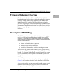
Description of EPPCBug
The EPPCBug package is a powerful evaluation and debugging
tool for systems built around the Motorola MBX Series boards.
Facilities are available for loading and executing user programs
under complete operator control for system evaluation. EPPCBug
includes commands for:
❏
Display and modification of memory
❏
Breakpoint and tracing capabilities
❏
Assembler/disassembler, useful for patching programs
Various EPPCBug routines that handle I/O, and general service
functions are available to user programs through the System Call
handler. The System Call handler is accessible through the system
call (SC) instruction, with exception vector $00C00 (System Call
Exception).
EPPCBug consists of:
A command-driven user-interactive software debugger, described in
Chapter 3 and hereafter referred to as the debugger or EPPCBug.
A user interface, which accepts commands from the system console
terminal. When using EPPCBug, you operate out of either the
debugger directory or the diagnostic directory.
PowerPC EPPCBug Firmware Package UserÕs Manual
2-3
Description of EPPCBug
If you are in the debugger directory, then the debugger prompt
EPPC-Bug> is displayed and you have all of the debugger
commands at your disposal.
2
If you are in the diagnostic directory, then the diagnostic prompt
EPPC-Diag> is displayed and you have all of the diagnostic
commands at your disposal as well as all of the debugger
commands.
You may switch between directories by using the Switch Directories
(SD) command, or examine the commands in the particular
directory that you are currently in by using the Help (HE)
command. Refer to Chapter 4 for debugger commands.
Because EPPCBug is command-driven, it performs its various
operations in response to user commands entered at the keyboard.
The ßow of control in EPPCBug is shown in the individual boardspeciÞc debugger manuals. When you enter a command, EPPCBug
executes the command and the prompt reappears. However, if you
enter a command that causes execution of user target code (for
instance GO), then control may or may not return to EPPCBug,
depending on the outcome of the user program.
Comparison with other Motorola Firmware
If you have used one or more of Motorola Computer Group's other
Þrmware debugging packages you will Þnd the PowerPC
EPPCBug very similar, after making due allowances for the
architectural differences between the microprocessor architectures.
These are primarily reßected in the instruction mnemonics, register
displays, addressing modes of the assembler/disassembler, and
argument passing to the system calls.
Data and address sizes are deÞned as follows:
2-4
❏
A byte is eight bits, numbered 0 through 7, with bit 7 being
the least significant.
❏
A half-word is 16 bits, numbered 0 through 15, with bit 15
being the least significant.
PowerPC EPPCBug Firmware Package UserÕs Manual
Introduction to PowerPC EPPCBug Firmware
❏
A word is 32 bits, numbered 0 through 31, with bit 31 being
the least significant.
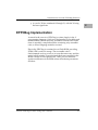
EPPCBug Implementation
As noted in the overview, EPPCBug is written largely in the C
programming language, which provides beneÞts of portability and
maintainability. Where necessary, assembler has been used in the
form of separately compiled modules containing only assembler
code, no mixed language modules are used.
Physically, EPPCBug is contained in one Flash ROM, providing
512Kb (128K words) of storage. The executable code is
checksummed at every power-on or reset Þrmware entry, and the
result (which includes a precalculated checksum contained in the
ROM) is tested for an expected zero. Thus, you are cautioned
against modiÞcation of the ROM unless rechecksum precautions
are taken.
PowerPC EPPCBug Firmware Package UserÕs Manual
2-5
2
General Installation and Startup
2
General Installation and Startup
Even though the EPPCBug FlashROM is installed on the MBX
module, for EPPCBug to operate properly with the MBX, follow
this general set-up procedure and the details given in the modulespeciÞc manual.
Note, that inserting or removing components or modules while
power is applied could damage module components.
1. Turn all equipment power OFF. Refer to the individual
module hardware manual and install/remove jumpers on
headers and/or set configuration switches as required for
your particular application.
2. Be sure that the EPPCBug Flash ROM is installed in the
proper socket on the MBX board. Refer to the module-specific
manual for details.
3. Refer to the set-up procedure for your particular chassis or
system for details concerning the installation of the MBX.
4. Connect the terminal which is to be used as the EPPCBug
system console to the default debug EIA-232-D port at the
proper location described in the MBX hardware manual.
5. Set up the terminal as follows:
Ð Eight bits per character
Ð One stop bit per character
Ð Parity disabled (no parity)
Ð Baud rate 9600 baud (default baud rate of MBX ports at
power-up)
6. After power-up, the baud rate of the debug port can be
reconfigured by using the Port Format (PF) command of the
EPPCBug debugger.
In order for high-baud rate serial communication between
EPPCBug and the terminal to work, the terminal must do some
form of handshaking. If your terminal does not do hardware
2-6
PowerPC EPPCBug Firmware Package UserÕs Manual
Introduction to PowerPC EPPCBug Firmware
handshaking via the CTS line, then it must do XON/XOFF
handshaking. If you get unintelligible messages and missing
characters, check the terminal to make sure XON/XOFF
handshaking is enabled.
2
If you want to connect a device, such as a host computer system
and/or a serial printer, to the other EIA-232-D port(s), connect the
appropriate cables and conÞgure the port(s) as detailed in step 5.
After power-up, you can reconÞgure the port by programming the
MBX console interface, or by using the EPPCBug PF command.
7. Power up the system. EPPCBug executes some self-checks
and displays the debugger prompt EPPC-Bug>.
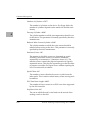
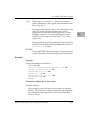
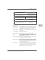
Hardware Initialization
Hardware initialization occurs from the hardware power-up/reset
state to some point prior to the initialization and/or setup of the
productÕs features. Normally, this initialization is performed only
once, during a reset.
The following list identiÞes the hardware components that are
initialized following the power-up/reset.
❏
MPC821/860 PowerPC Core
❏
MPC821/860 System Interface Unit (SIU)
❏
MPC821/860 Memory-Controller and Memory
❏
Primary PCI Bus Bridge Device (QSpan)
❏
ISA Bus Bridge Device (Winbond SL82C565)
❏
Super I/O Device (SMC FDC37C93X)
❏
PCI Device Configuration (PCI I/O and PCI Memory
Address Spaces)
❏
PCMCIA Module Configuration
❏
I/O and Memory Address Map
PowerPC EPPCBug Firmware Package UserÕs Manual
2-7
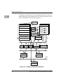
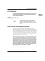
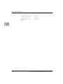
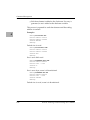
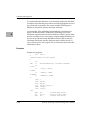
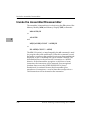
Hardware Initialization
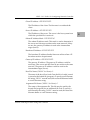
The hardware initialization follows a predetermined ßow, due to an
inherent hierarchy in the hardware.The following Þgure shows the
ßow of the hardware initialization sequence.
2
START/FLOW
MPC821/860 PowerPC Core
MPC821/860
MPC821/860 System Interface
SROM
MPC821/860 Memory Controller
I2C BUS
PCI Bus Bridge Device
DRAM (DIMM)
ISA Bus Bridge Device
MPC INTERNAL
BUS
Super I/O Device
DRAM
PCI Device Configuration
I/O and Memory Address
SYSTEM BUS
FLASH
BOOTROM
NVRAM
PCI BUS BRIDGE
PCMCIA SLOT
PCI BUS
ISA BUS BRIDGE
PCI SLOT
ISA BUS
SUPER I/O
Figure 2-2. Hardware Initialization Sequence
2-8
PowerPC EPPCBug Firmware Package UserÕs Manual
Introduction to PowerPC EPPCBug Firmware
Restarting the System
2
You can initialize the system to a known state in three different
ways: reset, break and abort. Each has characteristics which make it
more appropriate than the others in certain situations.
Reset
Powering up the MBX Series board initiates a system reset.
Additionally, reset can be asserted through the utility connector.
COLD and WARM reset modes are available. By default, EPPCBug
is in COLD mode (refer to the RESET command description in
Chapter 4.
During COLD reset, these system initialization processes occur, as
if the MBX had just been powered up.
❏
All static variables are restored to their default states
❏
Breakpoint table and offset registers are cleared
❏
Target registers are invalidated
❏
Input and output character queues are cleared
❏
Onboard devices are reset, and the first two serial ports are
reconfigured to their default state
During WARM reset, the EPPCBug variables and tables are
preserved, as are the target state registers and breakpoints. Revision
1.1 of the EPPCBug does not support the WARM reset feature.
Reset must be used if the processor ever halts or if the EPPCBug
environment is ever lost (vector table is destroyed, stack corrupted,
etc.).
Break
To invoke a Break, press and release the BREAK key on the terminal
keyboard. Break does not generate an interrupt. The only time
break is recognized is when characters are sent or received by the
PowerPC EPPCBug Firmware Package UserÕs Manual
2-9
Restarting the System
console port. Break removes any breakpoints in the user code and
keeps the breakpoint table intact. Break also takes a snapshot of the
machine state if the function was entered using SYSCALL. This
machine state is then accessible to you for diagnostic purposes.
2
Occasionally, it may be desirable to terminate a debugger command
prior to its completion, for example, the display of a large block of
memory. Break allows you to terminate the command.
Note
2-10
EPPCBug 1.1 does not support ABORT.
PowerPC EPPCBug Firmware Package UserÕs Manual
Introduction to PowerPC EPPCBug Firmware
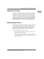
Diagnostic Facilities
2
Included in the EPPCBug package is a complete set of hardware
diagnostics intended for testing and troubleshooting of the MBX
Series boards. In order to use the diagnostics, you must switch
directories to the diagnostic directory. If you are in the debugger
directory, you can switch to the diagnostic directory by entering the
debugger command Switch Directories (SD). The EPPC-Diag>
prompt should appear. Note that some diagnostics depend on
restart defaults that are set up only in a particular restart mode.
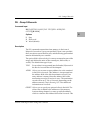
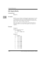
Memory Requirements
EPPCBug requires a minimum of 128Kb of contiguous read/write
memory to operate. This memory resides at the upper end of
memory. This read/write memory must not be modiÞed by a userÕs
application. This 128Kb is used for EPPCBug stack and static
variable space and the remainder is reserved as user space.
Whenever the MBX Series board is reset, the
❏
Target IP is initialized to the address corresponding to the
beginning of the user space, and
❏
Target stack pointers are initialized to addresses within the
user space, with the target Pseudo Stack Pointer (R1) set to the
top of the user space
PowerPC EPPCBug Firmware Package UserÕs Manual
2-11
I/O and Memory Address Map
2
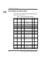
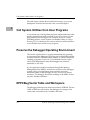
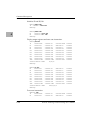
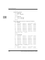
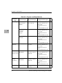
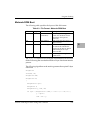
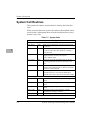
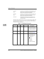
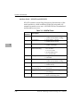
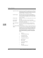
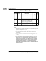
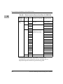
I/O and Memory Address Map
The hardware source of all address decode is the eight Òchip selectÓ
banks located within the MPC821/860. The Þrmware initializes the
systemÕs address map as follows:
Table 2-1. System Address Map - MPU View
2-12
Start
End
Size
DeÞnition
CS
Note
00000000
00XFFFFF
4/16M
On-Board DRAM
X = 3, 4M
X = F, 16M
1
1, 3, 12
00X00000
0XXXXXXX
xM
DIMM Slot (Bank 0 and 1)
(8/16/32/64M)
2, 3
1, 10, 11, 12
80000000
9FFFFFFF
512M
PCI/ISA I/O Space
5
A0000000
BFFFFFFF
512M
Reserved
C0000000
DFFFFFFF
512M
PCI/ISA Memory Space
5
2, 4, 7
E0000000
E3FFFFFF
64M
PCMCIA Memory Space
N/A
5, 13
E4000000
E7FFFFFF
64M
PCMCIA DMA Memory
Space
N/A
5, 13
E8000000
EBFFFFFF
64M
PCMCIA Attribute Space
N/A
5, 13
EC000000
EFFFFFFF
64M
PCMCIA I/O Space
N/A
F0000000
F9FFFFFF
160M
Unused
FA000000
FA0FFFFF
1M
NVRAM (BBRAM)
(32/128/512K Internal
Decode)
4
5, 7
FA100000
FA1FFFFF
1M
Status/Control Register
#1/#2
4
5, 7
FA200000
FA20FFFF
64K
MPC821/860 Dual Port
RAM
(16K Internal Decode)
N/A
5
FA210000
FA21FFFF
64K
PCI Bus Bridge
Control/Status Registers
(4K Internal Decode)
6
2, 4
FA220000
FBFFFFFF
30592K
Unused
FC000000
FC7FFFFF
1/2/4/8
M
FLASH Memory
(1/2/4/8M)
FC800000
FDFFFFFF
24M
Reserved
2, 4, 7
6
5, 13
6
6
0 or 7
3, 8, 9
6
PowerPC EPPCBug Firmware Package UserÕs Manual
Introduction to PowerPC EPPCBug Firmware
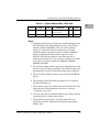
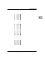
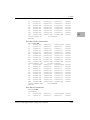
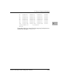
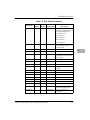
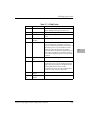
Table 2-1. System Address Map - MPU View
Start
End
Size
DeÞnition
FE000000
FE7FFFFF
8M
Boot ROM
(128/256/512K)
FE800000
FFFFFFFF
24M
Reserved
2
CS
0 or 7
Note
5, 8, 9
6
Notes
1. Dependent upon the size of memory installed (plugged into
the DIMM slot), the onboard memory may or may not be
located at address 00000000. If the size of the installed
memory is larger than the onboard memory, then the
installed memory should be located at address 00000000.
When configuring the bank address registers of the
MPC821/860, the base address of the bank must be a
modulus of the bank size. For example, If a bank was 32Mb,
it can only be located at addresses 00000000, 02000000,
04000000, 06000000.
2. The location of these address spaces are dependent upon the
presence of the PCI-bus host bridge. These address spaces are
programmable via the PCI-bus host bridge device (QSpan).
3. The size of these address spaces is queried from the SROM
device.
4. The presence of the PCI-bus host bridge device is queried
from the SROM device.
5. These address spaces are smaller than the indicated size. The
actual decode is dependent upon the device. Address
ÒwrappingÓ may occur.
6. Access to any reserved/unused address space either perform
a machine check or return useless data.
7. These address spaces share a common chip select, the
specified selection is further decoded by the appropriate
address lines.
PowerPC EPPCBug Firmware Package UserÕs Manual
2-13
I/O and Memory Address Map
8. The actual chip select used is dependent upon the position of
the Boot-ROM jumper (J-4). Chip select #0 is always utilized
by the MPC821/860 as the source to the reset vector.
2
9. EPPCBug can be executed from either the onboard FLASH or
the socketed FLASH the Boot ROM. EPPCBug configures the
reset FLASH device at the lower address, and the nonreset
FLASH device is configured at the higher address.
10. The DIMM is 64 data bits wide, however it can only be
accessed 32 bits at a time. The 32-bit data width is a limitation
of the MPC821/860. With this is mind, the DIMM can be
viewed as two contiguous banks of memory (bank 0 and bank
1). The RAS0 signal is logically connected to the first chip
selection and the RAS2 signal is logically connected to the
second chip selection.
11. When installing DIMM modules, ensure the jumpers
(J8/10/11) on the MBX Series board are configured to match
the size of the DIMM being installed. The MBX board
supports only 4K refresh single bank DIMM modules.
12. Both the onboard DRAM and the DIMM DRAM
share/utilize the same UPM, UPMA. UPMB is used for PCIbus resource bursting (when available).
13. PCMCIA decodes are enabled only if a PCMCIA card is
present in the PCMCIA socket.
For more information on initialization values for various hardware
components for the MBX Series boards, please refer to the MBX
Series ProgrammerÕs Guide.
2-14
PowerPC EPPCBug Firmware Package UserÕs Manual
Introduction to PowerPC EPPCBug Firmware
Terminal Input/Output Control
2
Information regarding command line control can be found in
Appendix D.
PowerPC EPPCBug Firmware Package UserÕs Manual
2-15
Terminal Input/Output Control
2
2-16
PowerPC EPPCBug Firmware Package UserÕs Manual
3Using the EPPCBug Debugger
3
How to Enter Debugger Command Lines
EPPCBug is command-driven and performs its various operations
in response to commands that you enter at the keyboard. When the
debugger prompt (EPPC-Bug>) appears on the terminal screen, the
debugger is ready to accept commands.
When you enter a command, it is stored in an internal buffer.
Execution begins only after you press RETURN. This allows you to
correct entry errors, if needed, using the control characters
described on page 3-2.
When you enter a command, the debugger executes the command
and the prompt reappears. However, if the command that you enter
causes execution of user target code, for example GO, then control
may or may not return to the debugger, depending on what the user
program does. For example, if a breakpoint has been speciÞed, then
control returns to the debugger when the breakpoint is encountered
during execution of the user program. Alternately, the user
program could return to the debugger by means of the System Call
Handler function .RETURN as described in Chapter Running H/F 3.
For more information, refer to the descriptions in Chapter Running
H/F 3 for the GD, GO, and GT commands.
In general, a debugger command is made up of the following parts:
1. The command identifier (MD or md for the Memory Display
command). Note that either uppercase or lowercase is
allowed.
2. A port number if the command is set up to work with more
than one port.
3. At least one intervening space before the first argument.
4. Any required arguments, as specified by command.
PowerPC EPPCBug Firmware Package UserÕs Manual
3-1
How to Enter Debugger Command Lines
5. An option field, set off by a semicolon (;) to specify conditions
other than the default conditions of the command.
6. The metasymbols used in the command syntax are:
3
boldface strings
A boldface string is a literal such as a command or
a program name. Type it just as it appears.
italic strings
An italic string is a "syntactic variable". Replace it
with one of a class of items it represents.
|
A vertical bar separating two or more items
indicates that a choice is to be made. Choose only
one of the items separated by this symbol.
[]
Square brackets enclose an item that is optional.
The item may appear zero or one time.
{}
Braces enclose an optional symbol that may occur
zero or more times.
Control Characters
Some commands, such as ENV, MM, or RM, allow you to edit
parameter Þelds or the contents of registers or memory. You may
use the following control characters to scroll through the listed
items:
3-2
V or v
Go to the next Þeld, register, or memory location. This is the
default, and remains in effect until changed by entering one of the
other special characters.
^
Back up to the previous Þeld register, or memory location. This
remains in effect until changed by entering one of the other
special characters.
=
Reopen the same Þeld register, or memory location.
.
Terminate the command, and return to EPPC-Bug> prompt
PowerPC EPPCBug Firmware Package UserÕs Manual
Using the EPPCBug Debugger
You may use the following control characters for limited editing
while entering commands at the EPPC-Bug> prompt. Additional
command line history and editing control characters are described
in Appendix D.
DEL
Delete: move the cursor back one position and erase the character
at the new cursor position. If a printer port is conÞgured
(hardcopy mode), a slash (/) character is typed along with the
deleted character.
CTRL-h
Performs the same function as DEL.
The XON and XOFF characters in effect for the terminal port may
be entered to control the output from any debugger command, if
the XON/XOFF protocol is enabled (default). The characters
initialized by EPPC-Bug are:
CTRL-s
Wait: halt console output (XON)
CTRL-q
Resume console output (XOFF).
Syntactic Variables
The following syntactic variables are encountered in the command
descriptions which follow. In addition, other syntactic variables
may be used and are deÞned in the particular command description
in which they occur.
DEL
Delimiter; either a comma or a space.
EXP
Expression (described in detail in a following section).
ADDR
Address (described in detail in a following section).
COUNT
Count; the syntax is the same as for EXP.
RANGE
A range of memory addresses which may be speciÞed either by
ADDR DEL ADDR or by ADDR : COUNT.
TEXT
An ASCII string of up to 255 characters, delimited at each end by
the single quote mark (').
PowerPC EPPCBug Firmware Package UserÕs Manual
3-3
3
How to Enter Debugger Command Lines
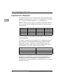
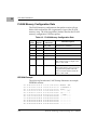
Expression as a Parameter
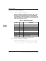
An expression can be one or more numeric values separated by the
arithmetic operators: plus (+), minus (-), multiplied by (*), divided
by (/), logical AND (&), shift left (<<), or shift right (>>).
3
Numeric values may be expressed in either hexadecimal, decimal,
octal, or binary by immediately preceding them with the proper
base identiÞer.
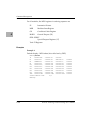
Data Type
Base
IdentiÞer
Examples
Integer
Hexadecimal
$
$FFFFFFFF
Integer
Decimal
&
&1974, &10-&4
Integer
Octal
@
@456
Integer
Binary
%
%1000110
If no base identiÞer is speciÞed, then the numeric value is assumed
to be hexadecimal.
A numeric value may also be expressed as a string literal of up to
four characters. The string literal must begin and end with the
single quote mark ('). The numeric value is interpreted as the
concatenation of the ASCII values of the characters. This value is
right-justiÞed, as any other numeric value would be.
String Literal
Numeric Value (In Hexadecimal)
'A'
41
'ABC'
414243
'TEST'
54455354
Evaluation of an expression is always from left to right unless
parentheses are used to group part of the expression. There is no
operator precedence. Subexpressions within parentheses are
evaluated Þrst. Nested parenthetical subexpressions are evaluated
from the inside out.
3-4
PowerPC EPPCBug Firmware Package UserÕs Manual
Using the EPPCBug Debugger
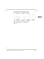
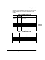
Valid expression examples:
Expression
Result (In
Hexadecimal)
FF0011
FF0011
45+99
DE
&45+&99
90
@35+@67+@10
5C
Notes
3
%10011110+%1001
A7
88<<4
880
shift left
AA&F0
A0
logical AND
The total value of the expression must be between 0 and $FFFFFFFF.
Address as a Parameter
Many commands use ADDR as a parameter. The syntax accepted
by EPPCBug is similar to the one accepted by the PowerPC one-line
assembler. All control addressing modes are allowed. An "address
+ offset register" mode is also provided.
Address Formats
Addresses are entered as a hexadecimal number. For instance,
20000 would correspond to address $00020000. The address, or
starting address of a range, can be qualiÞed by a sufÞx of the form
^S, ^s, ^U, or ^u where S or s deÞnes Supervisor address space, and
U or u deÞnes user address space. The default, when the qualiÞer is
not speciÞed, is Supervisor.
Note
EPPCBUG 1.1 does not support the address space
qualifier.
Once a qualiÞer has been entered, it remains valid for all addresses
entered for that command sequence, until the EPPCBug is
reentered or another qualiÞer is provided.
PowerPC EPPCBug Firmware Package UserÕs Manual
3-5
How to Enter Debugger Command Lines
An alternate form of address is Rn, which tells the bug to use the
address contained in MPU Register Rn, where n=0 through 31 (0, 1,
..., or 31).
3
Hence ADDR:= Hexadecimal Number{[^S]|[^s]|[^U]|[^u]}|Rn
In commands with RANGE speciÞed as ADDR DEL ADDR, and
with size option H or W chosen, data at the second (ending) address
is acted on only if the second address is a proper boundary for a
half-word or word, respectively. Otherwise, the range is truncated
so that the last byte acted upon is at an address that is a proper
boundary.
Offset Registers
Eight pseudo-registers (Z0-Z7) called offset registers are used to
simplify the debugging of relocatable and position-independent
modules. The listing Þles in these types of programs usually start at
an address (normally 0) that is not the one at which they are loaded.
This makes it harder to correlate addresses in the listing with
addresses in the loaded program. The offset registers solve this
problem by taking into account this difference and forcing the
display of addresses in a relative address+offset format. Offset
registers have adjustable ranges and may even have overlapping
ranges. The range for each offset register is set by two addresses:
base and top. Specifying the base and top addresses for an offset
register sets its range. In the event that an address falls in two or
more offset registers' ranges, the one that yields the least offset is
chosen.
Relative addresses are limited to 1Mb (5 digits), regardless of the
range of the closest offset register.
3-6
PowerPC EPPCBug Firmware Package UserÕs Manual
Using the EPPCBug Debugger
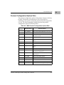
Port Numbers
Some EPPCBug commands give you the option to choose the port
to be used to input or output. Valid port numbers which may be
used for these commands are:
EPPCBug Port Numbers
PORT0
SMC Port 1. Sometimes known as the console port. It is
used for interactive user input/output by default.
PORT1
SMC Port 2. Sometimes known as the host port. This is
the default for downloading, uploading and transparent
modes.
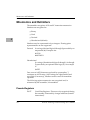
How to Enter and Debug Programs
There are various ways to enter a user program into system
memory for execution. One way is to create the program using the
Memory Modify (MM) command with the assembler/disassembler
option. You enter the program one source line at a time. After each
source line is entered, it is assembled and the object code is loaded
to memory. Refer to Chapter Running H/F 3 for complete details of
the EPPCBug Assembler/Disassembler.
Another way to enter a program is to download an object Þle from
a host system. The program must be in S-record format and may
have been assembled or compiled on the host system. Alternately,
the program may have been previously created using the EPPCBug
MM command as outlined above and stored to the host using the
Dump (DU) command. A communication link must exist between
the host system and the MBX serial port. Refer to the Installation
guide for the MBX Series boards. The Þle is downloaded from the
host to MBX memory by the Load (LO) command.
Additionally, the PL command allows programs to be loaded from
network or mass storage I/O devices.
PowerPC EPPCBug Firmware Package UserÕs Manual
3-7
3
Call System Utilities from User Programs
Once the object code has been loaded into memory, you can set
breakpoints if desired and run the code or trace through it.
3
Call System Utilities from User Programs
A convenient way of doing character input/output and many other
useful operations has been provided so you do not have to write
these routines into the target code. You have access to various
EPPCBug routines via the System Call Handler. Refer to Chapter
Running H/F 3 for details on the various utilities available and how
to invoke them from within a user program.
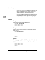
Preserve the Debugger Operating Environment
This section explains how to avoid contaminating the operating
environment of the debugger. EPPCBug uses certain MBX onboard
resources and also offboard system memory to contain temporary
variables, exception vectors, etc. If you disturb resources upon
which EPPCBug depends, then the debugger may function
unreliably or not at all.
If your application enables translation through the Memory
Management Unit (MMU), and utilizes resources of the debugger
(system calls), your application must create the necessary
translation tables for the debugger to have access to its various
resources. The debugger honors the enabling of the MMU. It does
not alter/disable translation.
EPPCBug Vector Table and Workspace
The debugger and diagnostic Þrmware resides in EPROM. The last
128Kb of RAM are also used by the debugger for storage of the
vector table, executable code, variables, and stack.
3-8
PowerPC EPPCBug Firmware Package UserÕs Manual
Using the EPPCBug Debugger
Hardware Functions
The only hardware resources used by the debugger are the
EIA-232-D ports, which are initialized to interface to the debug
terminal. If these ports are reprogrammed, the terminal
characteristics must be modiÞed to suit, or the ports should be
restored to the debugger-set characteristics prior to reinvoking the
debugger.
Exception Vectors Used by EPPCBug
These exception vectors are reserved for use by the debugger:
00100
System Reset
Used for the ABORT Switch soft reset
feature.
00700
Program
Used for instruction breakpoints.
00C00
System Call
Used for the System Call Handler.
Note that revision 1.1 of the
EPPCBug this feature is not
supported.
00D00
Used for instruction tracing.
Run Mode
These vectors may be taken over under an userÕs application.
However, prior to returning control to the debugger these vectors
must be restored for proper operation of the affected features.
PowerPC EPPCBug Firmware Package UserÕs Manual
3-9
3
MPU/CPU Registers
MPU/CPU Registers
Certain MPU/CPU registers must be preserved for their speciÞc
uses.
3
MPU Register SPR272
MPU register SPR272 is reserved for use by the debugger. If SPR272
is to be used by the user program, it must be restored prior to
utilizing debugger resources (system calls) and or returning control
to the debugger.
MPU Registers SPR273-SPR275
These MPU registers are utilized by debugger as scratch registers.
Context Switching
Context switching is viewed as switching from the debugger state
to the user (target) state, or vice a versa. This switching occurs upon
the invocation of debugger commands GD, GN, GO, GT, T, and TT,
or the return from user state to the debugger state.
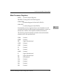
When the context switch transitions from the user state to the
debugger state, the following MPU registers are captured:
3-10
R0-R31
General Purpose Registers
SPRns
Special Purpose Registers (SPR1, SPR8, SPR9, SPR18, SPR19, SPR22,
SPR26, SPR27, SPR268, PSR269, SPR272, SPR273, SPR274, SPR275,
SPR284, SPR285,SPR286)
IP
Instruction Pointer (copy of SPR26)
MSR
Machine State Register (copy of SPR27)
CR
Condition Register
PowerPC EPPCBug Firmware Package UserÕs Manual
Using the EPPCBug Debugger
When the context switch transitions from the debugger state to the
user state, the following MPU registers are restored:
R0-R31
General Purpose Registers
SPR26
Restored from IP Register Image
SPR27
Restored from MSR Register Image
SPRns
Special Purpose Registers (SPR1, SPR8, SPR9, SPR275)
CR
Condition Register
3
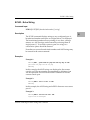
Floating Point Support
For EPPCBug, the commands MD and MM have been extended to
allow display and modiÞcation of ßoating point data in memory.
Floating point instructions can be assembled/disassembled with
the DI option of the MD and MM commands.
Valid data types that can be used when modifying a ßoating point
data register or a ßoating point memory location:
Integer Data Types
12
Byte
1234
Half-Word
12345678
Word
Floating Point Data Types
1_FF_7FFFFF
Single Precision Real Format
1_7FF_FFFFFFFFFFFFF
Double Precision Real Format
-3.12345678901234501_E+123
ScientiÞc Notation Format (decimal)
When entering data in single or double precision format, the
following rules must be observed:
1. The sign field is the first field and is a binary field.
2. The exponent field is the second field and is a hexadecimal
field.
PowerPC EPPCBug Firmware Package UserÕs Manual
3-11
Single Precision Real
3. The mantissa field is the last field and is a hexadecimal field.
4. The sign field, the exponent field, and at least the first digit of
the mantissa field must be present (any unspecified digits in
the mantissa field are set to zero).
3
5. Each field must be separated from adjacent fields by an
underscore.
6. All the digit positions in the sign and exponent fields must be
present.
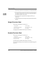
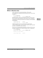
Single Precision Real
This format would appear in memory as:
1-bit sign Þeld
(1 binary digit)
8-bit biased exponent Þeld
(2 hex digits. Bias = $7F)
23-bit fraction Þeld
(6 hex digits)
A single precision number takes 4 bytes in memory.
Double Precision Real
This format would appear in memory as:
1-bit sign Þeld
(1 binary digit)
11-bit biased exponent Þeld
(3 hex digits. Bias = $3FF)
52-bit fraction Þeld
(13 hex digits)
A double precision number takes 8 bytes in memory.
The single and double precision formats have an implied integer bit
(always 1).
3-12
PowerPC EPPCBug Firmware Package UserÕs Manual
Using the EPPCBug Debugger
Scientific Notation
This format provides a convenient way to enter and display a
ßoating point decimal number. Internally, the number is assembled
into a packed decimal number and then converted into a number of
the speciÞed data type.
Entering data in this format requires the following Þelds:
❏
An optional sign bit (+ or -)
❏
One decimal digit followed by a decimal point
❏
Up to 17 decimal digits (at least one must be entered)
❏
An optional Exponent field that consists of:
Ð An optional underscore
Ð The Exponent field identifier, letter "E"
Ð An optional Exponent sign (+, -)
Ð From 1 to 3 decimal digits
PowerPC EPPCBug Firmware Package UserÕs Manual
3-13
3
Scientific Notation
3
3-14
PowerPC EPPCBug Firmware Package UserÕs Manual
4Debugger Commands
4
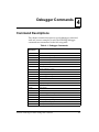
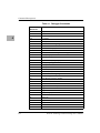
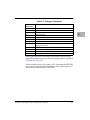
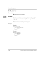
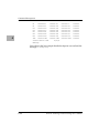
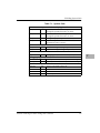
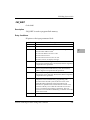
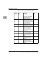
Command Descriptions
This chapter contains descriptions of each debugger command,
with one or more examples of each.The EPPCBug debugger
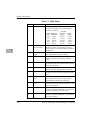
commands are summarized in the following table.
Table 4-1. Debugger Commands
Command
Mnemonic
Title
AS
One Line Assembler
BC
Block of Memory Compare
BF
Block of Memory Fill
BI
Block of Memory Initialize
BM
Block of Memory Move
BR/NOBR
Breakpoint Insert/Delete
BS
Block of Memory Search
BV
Block of Memory Verify
CS
Checksum a Block of Data
CSAR
PCI ConÞguration Space READ Access
CSAW
PCI ConÞguration Space WRITE Access
DC
Data Conversion
DS
One Line Disassembler
DTT
Display Temperature
DU
Dump S-Records
ECHO
Echo String
ENV
Edit Environment
GD
Go Direct (Ignore Breakpoints)
GN
Go to Next Instruction
GO
Go Execute User Program
GT
Go to Temporary Breakpoint
HBD
History Buffer Display
HBX
History Buffer Entry-Execute
PowerPC EPPCBug Firmware Package UserÕs Manual
4-1
Command Descriptions
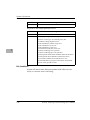
Table 4-1. Debugger Commands
4
Command
Mnemonic
Title
HE
Help
I2C
I2C Device Read/Write
IOC
I/O Control for Disk
IOI
I/O Inquiry
IOP
I/O Physical to Disk
IOT
I/O ÒTeachÓ for ConÞguring Disk Controller
LO
Load S-Records from Host
MA/NOMA
Macro DeÞne/Display/Delete
MAE
Macro Edit
MAL/NOMAL Enable/Disable Macro Expansion Listing
4-2
MD/MDS
Memory Display
MM
Memory Modify
MMAP
MPC8xx Memory Map Display
MMD
Memory Map Diagnostic
MS
Memory Set
MW
Memory Write
NIOC
Network I/O Control
NIOP
Network I/O Physical
NIOT
I/O ÒTeachÓ for ConÞguring Network Controller
NPING
Network Ping
OF
Offset Registers Display/Modify
PA/NOPA
Printer Attach/Detach
PF/NOPF
Port Format/Detach
PFLASH
Program FLASH Memory
PL
Program Load
PLH
Program Load and Halt
RD
Register Display
RESET
Cold/Warm Reset
RL
Read Loop
RM
Register Modify
RS
Register Set
SD
Switch Directories
SET
Set Time and Date
PowerPC EPPCBug Firmware Package UserÕs Manual
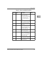
Table 4-1. Debugger Commands
Command
Mnemonic
Title
SYM/NOSYM
Symbol Table Attach/Detach
SYMS
Symbol Table Display/Search
T
Trace
TA
Terminal Attach
TIME
Display Time and Date
TM
Transparent Mode
TT
Trace to Temporary Breakpoint
UPM
MPC8xx User Programmable Memory (UPM)
Display/Read/Write
VE
Verify S-Records Against Memory
VER
Revision/Version Display
VPD
VPD (Vital Product Data) Display
WL
Write Loop
4
Each of the individual commands is described in the following
pages.The command syntax is shown using the symbols explained
in Chapter Running H/F 3.
In the examples shown, the symbol <CR> represents the RETURN
key on your terminal keyboard.Whenever this symbol appears, it
means that you should enter a RETURN.
PowerPC EPPCBug Firmware Package UserÕs Manual
4-3
Command Descriptions
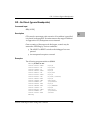
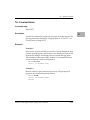
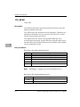
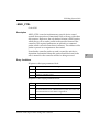
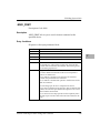
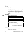
AS - One Line Assembler
Command Input
AS ADDR
4
Description
This is synonymous with the MM ADDR;DI command. Refer to
MM - Memory Modify on page 4-89 for details. It provides access to
the one-line assembler described in Chapter Running H/F 3.
Accordingly, it is not described further here.
4-4
PowerPC EPPCBug Firmware Package UserÕs Manual
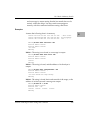
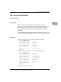
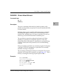
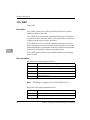
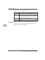
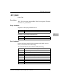
BC - Block of Memory Compare
BC - Block of Memory Compare
Command Input
BC RANGE DEL ADDR [;B|H|W]
Options
4
B Byte
H Half-word
W Word
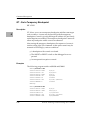
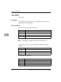
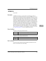
Description
The BC command compares the contents of memory deÞned by
RANGE with another place in memory, beginning at ADDR.
The option Þeld B, H, or W (upper or lower case) deÞnes the size of
data compared, and if RANGE is speciÞed using a count, deÞnes
the size of data element to which the count refers. For example, a
count of 4 with an option of W would mean to compare 4 words (16
bytes). The default data type is word.
If the RANGE beginning address is greater than or equal to the end
address, an error message is displayed and no comparison takes
place.
For the following examples, assume that memory blocks
20000-20020 and 21000-21020 contain identical data.
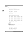
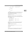
Examples
Example 1:
EPPC-Bug>BC 20000 2001F 21000 <CR>
Effective address: 00020000
Effective address: 0002001F
Effective address: 00021000
EPPC-Bug>
Memory compare, nothing printed.
PowerPC EPPCBug Firmware Package UserÕs Manual
4-5
Command Descriptions
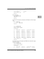
Example 2:
EPPC-Bug>BC 20000:20 21000;B <CR>
Effective address: 00020000
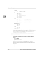
Effective count : &32
Effective address: 00021000
EPPC-Bug>
4
Memory compare, nothing printed.
Example 3:
EPPC-Bug>MM 2100F;B <CR>
0002100F 21? 0. <CR>
EPPC-Bug>
Create a mismatch.
EPPC-Bug>BC 20000:20 21000;B <CR>
Effective address: 00020000
Effective count : &32
Effective address: 00021000
0002000F|21 0002100F|00
EPPC-Bug>
Mismatches are printed out.
4-6
PowerPC EPPCBug Firmware Package UserÕs Manual
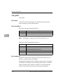
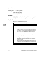
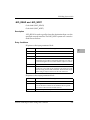
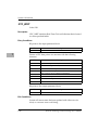
BF - Block of Memory Fill
BF - Block of Memory Fill
Command Input
BF RANGE DEL data [DEL increment] [;B|H|W]
where data and increment are both expression parameters.
4
Options
(length of data Þeld):
B Byte
H Half-word
W Word
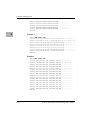
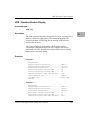
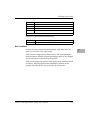
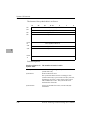
Description
The BF command Þlls the speciÞed range of memory with a data
pattern. If an increment is speciÞed, then data is incremented by
this value following each write, otherwise data remains a constant
value. A decrementing pattern may be accomplished by entering a
negative increment. The data you enter is right-justiÞed in either a
byte, half-word, or word Þeld (as speciÞed by the option selected).
The default Þeld length is W (word).
If data you entered does not Þt into the data Þeld size, then leading
bits are truncated to make it Þt. If truncation occurs, then a message
is printed stating the data pattern which was actually written (or
initially written if you speciÞed an increment).
If the increment you entered does not Þt into the data Þeld size, then
leading bits are truncated to make it Þt. If truncation occurs, then a
message is printed stating the increment which was actually used.
If the upper address of the range is not on the correct boundary for
an integer multiple of the data to be stored, then data is stored to the
last boundary before the upper address. No address outside of the
speciÞed range is ever disturbed in any case. The "Effective
address" messages displayed by the command show exactly where
data was stored.
PowerPC EPPCBug Firmware Package UserÕs Manual
4-7
Command Descriptions
Examples
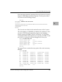
Example 1:
Assume memory from $20000 through $2002F is clear.
EPPC-Bug>BF 20000,2001F 4E71 <CR>
Effective address: 00020000
Effective address: 0002001F
EPPC-Bug>
4
EPPC-Bug>MD 20000:18;H <CR>
00020000 0000 4E71 0000 4E71 0000 4E71 0000 4E71 ..Nq..Nq..Nq..Nq
00020010 0000 4E71 0000 4E71
0000 4E71 0000 4E71 ..Nq..Nq..Nq..Nq
00020020 0000 0000 0000 0000 0000 0000 0000 0000 ................
Because no option was speciÞed, the length of the data Þeld
defaulted to word.
Example 2:
Assume memory from $20000 through $2002F is clear.
EPPC-Bug>BF 20000:10 4E71;B <CR>
Effective address: 00020000
Effective count : &16
Data = $71
EPPC-Bug>
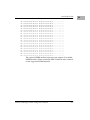
EPPC-Bug>MD 20000:18;H <CR>
00020000 7171 7171 7171 7171 7171 7171 7171 7171
00020010 0000 0000 0000 0000 0000 0000 0000 0000
00020020 0000 0000 0000 0000 0000 0000 0000 0000
EPPC-Bug>
qqqqqqqqqqqqqqqq
................
................
The speciÞed data did not Þt into the speciÞed data Þeld size. The
data was truncated and the "Data = " message was output.
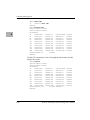
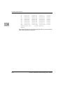
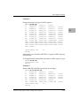
Example 3:
Assume memory from $20000 through $2002F is clear.
EPPC-Bug>BF 20000,20006 12345678;W <CR>
Effective address: 00020000
Effective address: 00020003
EPPC-Bug>
4-8
PowerPC EPPCBug Firmware Package UserÕs Manual
BF - Block of Memory Fill
EPPC-Bug>MD 20000:18;H <CR>
00020000 1234 5678 0000 0000 0000 0000 0000 0000
00020010 0000 0000 0000 0000 0000 0000 0000 0000
00020020 0000 0000 0000 0000 0000 0000 0000 0000
.4Vx............
................
................
The word pattern would not Þt evenly in the given range. Only one
word was written and the "Effective address" messages reßect the
fact that data was not written all the way up to the speciÞed
address.
Example 4:
Assume memory from $20000 through $2002F is clear.
EPPC-Bug>BF 20000:18 0 1;H <CR>
Effective address: 00020000
Effective count : &48
EPPC-Bug>
EPPC-Bug>MD 20000:18;H <CR>
00020000 0000 0001 0002 0003 0004 0005 0006 0007
00020010 0008 0009 000A 000B 000C 000D 000E 000F
00020020 0010 0011 0012 0013 0014 0015 0016 0017
EPPC-Bug>
PowerPC EPPCBug Firmware Package UserÕs Manual
................
................
................
4-9
4
Command Descriptions
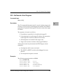
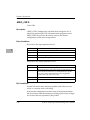
BI - Block of Memory Initialize
Command Input
BI RANGE [;B|H|W]
4
Options
B Byte
H Half-word
W Word
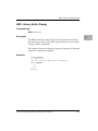
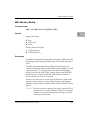
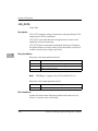
Description
The BI command may be used to initialize parity for a block of
memory. The BI command is nondestructive. If the parity is correct
for a memory location, then the contents of that memory location
are not altered.
The limits of the block of memory to be initialized may be speciÞed
using a RANGE. The option Þeld speciÞes the data size in which
memory is initialized if RANGE is speciÞed using a COUNT. The
option also speciÞes the size of data element to which the COUNT
refers. The length option is valid only when a COUNT is entered.
The default data type is word.
BI works through the memory block by reading from locations and
checking parity. If the parity is not correct, then the data read is
written back to the memory location in an attempt to correct the
parity. If the parity is not correct after the write, then the message
"RAM FAIL" is output and the address is given.
This command may take several seconds to initialize a large block
of memory.
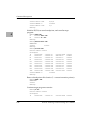
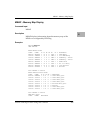
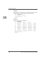
Examples
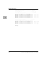
Example 1:
EPPC-Bug>BI 0:10000;B <CR>
Effective address: 00000000
4-10
PowerPC EPPCBug Firmware Package UserÕs Manual
BI - Block of Memory Initialize
Effective count : &65536
EPPC-Bug>
Example 2:
Assume system memory from $0 to $000FFFFF.
EPPC-Bug>BI 0,1FFFFF <CR>
Effective address: 00000000
Effective address: 001FFFFF
RAM FAIL AT $00100000
EPPC-Bug>
PowerPC EPPCBug Firmware Package UserÕs Manual
4
4-11
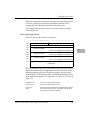
Command Descriptions
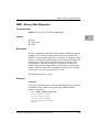
BM - Block of Memory Move
Command Input
BM RANGE DEL ADDR [;B|H|W]
4
Options
B Byte
H Half-word
W Word
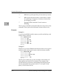
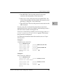
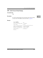
Description
The BM command copies the contents of the memory addresses
deÞned by RANGE to another place in memory, beginning at
ADDR.
The option Þeld is only allowed when RANGE is speciÞed using a
COUNT. In this case, the B, H, or W deÞnes the size of data that the
COUNT is referring to. For example, a COUNT of 4 with an option
of W would mean to move 4 words (or 16 bytes) to the new location.
If an option Þeld is speciÞed without a COUNT in the RANGE, an
error results. The default data type is Word.
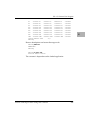
Examples
Example 1:
Assume memory from 20000 to 2000F is clear.
EPPC-Bug>MD 21000:10;H <CR>
00021000 5448 4953 2049 5320 4120 5445 5354 2121
00021010 0000 0000 0000 0000 0000 0000 0000 0000
EPPC-Bug>
THIS IS A TEST!!
................
EPPC-Bug>BM 21000 2100F 20000 <CR>
Effective address: 00021000
Effective address: 0002100F
Effective address: 00020000
EPPC-Bug>
4-12
PowerPC EPPCBug Firmware Package UserÕs Manual
BM - Block of Memory Move
EPPC-Bug>MD 20000:10;H <CR>
00020000 5448 4953 2049 5320 4120 5445 5354 2121
00020010 0000 0000 0000 0000 0000 0000 0000 0000
EPPC-Bug>
THIS IS A TEST!!
................
Example 2:
This utility is very useful for patching assembly code in memory.
Suppose you had a short program in memory at address 20000.
EPPC-Bug>MD 20000
00020000 3C401000
00020004 60420001
00020008 7C631378
0002000C 7CA53214
EPPC-Bug>
2000F;DI <CR>
ADDIS
R2,R0,$1000
ORI
R2,R2,$1
OR
R3,R3,R2
ADD
R5,R5,R6
Now, you would like to insert an ANDC between the OR
instruction and the ADD instruction. You should Block Move the
object code down four bytes to make room for the ANDC.
EPPC-Bug>BM 20008 20010 2000C <CR>
Effective address: 00020008
Effective address: 0002000F
Effective address: 0002000C
EPPC-Bug>
EPPC-Bug>MD 20000
00020000 3C401000
00020004 60420001
00020008 7C631378
0002000C 7C631378
00020010 7CA53214
EPPC-Bug>
20014;DI <CR>
ADDIS
R2,R0,$1000
ORI
R2,R2,$1
OR
R3,R3,R2
OR
R3,R3,R2
ADD
R5,R5,R6
Now you need to simply enter the ANDC at address 20008.
EPPC-Bug>MM 20008;DI <CR>
00020008 7C631378 OR
00020008 7C631078 ANDC
0002000C 7C631378 OR
EPPC-Bug>
R3,R3,R2? ANDC R3,R3,R2 <CR>
R3,R3,R2
R3,R3,R2? . <CR>
EPPC-Bug>MD 20000 20014;DI <CR>
00020000 3C401000 ADDIS
R2,R0,$1000
PowerPC EPPCBug Firmware Package UserÕs Manual
4-13
4
Command Descriptions
00020004 60420001
00020008 7C631078
0002000C 7C631378
00020010 7CA53214
EPPC-Bug>
ORI
ANDC
OR
ADD
R2,R2,$1
R3,R3,R2
R3,R3,R2
R5,R5,R6
4
4-14
PowerPC EPPCBug Firmware Package UserÕs Manual
BR - Breakpoint Insert/Delete
BR - Breakpoint Insert/Delete
Command Input
BR [ADDR[:COUNT]]
NOBR [ADDR]
4
Description
The BR command allows you to set a target code instruction
address as a "breakpoint address" for debugging purposes. If,
during target code execution, a breakpoint with 0 count is found,
the target code state is saved in the target registers and control is
returned back to EPPCBug. This allows you to see the actual state
of the processor at selected instructions in the code.
Up to eight breakpoints can be deÞned. The breakpoints are kept in
a table which is displayed each time either BR or NOBR is used. If
an address is speciÞed with the BR command, that address is added
to the breakpoint table. The COUNT Þeld speciÞes how many times
the instruction at the breakpoint address must be fetched before a
breakpoint is taken. The count, if greater than zero, is decremented
with each fetch. Every time that a breakpoint with zero count is
found, a breakpoint handler routine prints the CPU state on the
screen and control is returned to EPPCBug.
NOBR is used for deleting breakpoints from the breakpoint table. If
an address is speciÞed, then that address is removed from the
breakpoint table. If NOBR <RETURN> is entered, then all entries
are deleted from the breakpoint table and the empty table is
displayed.
Examples
EPPC-Bug>BR 1E000,1E200 1E700:&12 <CR>
BREAKPOINTS
0001E000
0001E200
0001E700:C
EPPC-Bug>
PowerPC EPPCBug Firmware Package UserÕs Manual
4-15
Command Descriptions
Set some breakpoints.
EPPC-Bug>NOBR 1E200 <CR>
BREAKPOINTS
0001E000
0001E700:C
EPPC-Bug>
Delete speciÞed breakpoint.
4
EPPC-Bug>NOBR <CR>
BREAKPOINTS
EPPC-Bug>
Delete all breakpoints.
4-16
PowerPC EPPCBug Firmware Package UserÕs Manual
BS - Block of Memory Search
BS - Block of Memory Search
Command Input
BS RANGE DEL TEXT [;B|H|W]
or
4
BS RANGE DEL data [DEL mask] [;B|H|W [,N][,V]]
Options
B Byte
H Half-word
W Word
Description
The BS command searches the speciÞed range of memory for a
match with a user-entered data pattern. This command has three
modes, as described below.
Mode 1 - Literal String Search
In this mode, a search is carried out for the ASCII equivalent of the
literal string you entered. This mode is assumed if the single
quote (') indicating the beginning of a TEXT Þeld is encountered
following RANGE. The size as speciÞed in the option Þeld tells
whether the COUNT Þeld of RANGE refers to bytes, half-words,
or words. If RANGE is not speciÞed using a COUNT, then no
options are allowed. If a match is found, then the address of the
Þrst byte of the match is output.
Mode 2 - Data Search
In this mode, you enter a data pattern as part of the command line
and either enter a size in the option Þeld or it will be is assumed
(the assumption is word). The size entered in the option Þeld also
dictates whether the COUNT Þeld in RANGE refers to bytes, halfwords, or words. The following actions occur during a data
search:
PowerPC EPPCBug Firmware Package UserÕs Manual
4-17
Command Descriptions
1. The user-entered data pattern is right-justified and leading
bits are truncated or leading zeros are added as necessary to
make the data pattern the specified size.
2. A compare is made with successive bytes, half-words, or
words (depending on the size in effect) within the range for a
match with the user-entered data. Comparison is made only
on those bits at bit positions corresponding to a "1" in the
mask. If no mask is specified, then a default mask of all ones
is used (all bits are compared). The size of the mask is taken
to be the same size as the data. The default data size is word.
4
3. If the N (nonaligned) option has been selected, then the data
is searched for on a byte-by-byte basis, rather than by halfwords or words, regardless of the size of data. This is useful
if a half-word (or word) pattern is being searched for, but is
not expected to lie on a half-word (or word) boundary.
4. If a match is found, then the address of the first byte of the
match is output along with the memory contents. If a mask
was in use, then the actual data at the memory location is
displayed, rather than the data with the mask applied.
Mode 3 - Data VeriÞcation
If the V (verify) option has been selected, then displaying of
addresses and data is done only when the memory contents do
NOT match the user-speciÞed pattern. Otherwise this mode is
identical to the Mode 2.
For all three modes, information on matches is output to the
screen in a four-column format. If more than 24 lines of matches
are found, then output is inhibited to prevent the Þrst match from
rolling off the screen. A message is printed at the bottom of the
screen indicating that there is more to display. To resume output,
you should simply press any character key. To cancel the output
and exit the command, you should press the BREAK key.
If a match is found (or, in the case of Mode 3, a mismatch) with a
series of bytes of memory whose beginning is within the range
but whose end is outside of the range, then that match is output
4-18
PowerPC EPPCBug Firmware Package UserÕs Manual
BS - Block of Memory Search
and a message is output stating that the last match does not lie
entirely within the range. You may search noncontiguous
memory with this command without causing a Bus Error.
Examples
Assume the following data is in memory.
00030000 0000 0045 7272 6F72 2053 7461 7475 733D
00030010 3446 2F2F 436F 6E66 6967 5461 626C 6553
00030020 7461 7274 3A00 0000 0000 0000 0000 0000
...Error Status=
4F//ConfigTableS
tart:...........
EPPC-Bug>BS 30000 3002F 'Task Status' <CR>
Effective address: 00030000
Effective address: 0003002F
-not foundEPPC-Bug>
Mode 1: The string is not found, so a message is output.
EPPC-Bug>BS 30000 3002F 'Error Status' <CR>
Effective address: 00030000
Effective address: 0003002F
00030003
EPPC-Bug>
Mode 1: The string is found, and the address of its Þrst byte is
output.
EPPC-Bug>BS 30000 3001F 'ConfigTableStart' <CR>
Effective address: 00030000
Effective address: 0003001F
-last match extends over range boundaryEPPC-Bug>
Mode 1: The string is found, but it ends outside of the range, so the
address of its Þrst byte and a message are output.
EPPC-Bug>BS 30000:30 't';B <CR>
Effective address: 00030000
Effective count : &48
0003000A 0003000C 00030020 00030023
EPPC-Bug>
PowerPC EPPCBug Firmware Package UserÕs Manual
4-19
4
Command Descriptions
Mode 1, using RANGE with count and size option: count is
displayed in decimal, and address of each occurrence of the string
is output.
EPPC-Bug>BS 30000:18,2F2F;H <CR>
Effective address: 00030000
Effective count : &48
00030012|2F2F
EPPC-Bug>
4
Mode 2, using RANGE with count: count is displayed in decimal
bytes, and the data pattern is found and displayed.
EPPC-Bug>BS 30000,3002F 3D34 <CR>
Effective address: 00030000
Effective address: 0003002F
-not foundEPPC-Bug>
Mode 2, the default size is word and the data pattern is not found,
so a message is output.
EPPC-Bug>BS 30000,3002F 3D34;HN <CR>
Effective address: 00030000
Effective Address: 0003002F
0003000F|3D34
EPPC-Bug>
Mode 2, the size is half-word and non-aligned option is used, so the
data pattern is found and displayed.
EPPC-Bug>BS 30000:30 60,F0;B <CR>
Effective address: 00030000
Effective count : &48
00030006|6F 0003000B|61 00030015|6F
00030017|66 00030018|69 00030019|67
0003001C|62 0003001D|6C 0003001E|65
EPPC-Bug>
00030016|6E
0003001B|61
00030021|61
Mode 2, using RANGE with count, mask option, and size option:
count is displayed in decimal, and the actual unmasked data
patterns found are displayed.
EPPC-Bug>BS 3000 1FFFF 0000 000F;VH <CR>
Effective address: 00003000
Effective address: 0001FFFF
0000C000|E501 0001E224|A30E
4-20
PowerPC EPPCBug Firmware Package UserÕs Manual
BS - Block of Memory Search
EPPC-Bug>
Mode 3, on a different block of memory, mask option, scan for
words with low nibble nonzero: two locations failed to verify.
4
PowerPC EPPCBug Firmware Package UserÕs Manual
4-21
Command Descriptions
BV - Block of Memory Verify
Command Input
BV RANGE DEL data [increment] [;B|H|W]
Where data and increment are both expression parameters.
4
Options
B Byte
H Half-word
W Word
Description
The BV command compares the speciÞed range of memory against
a data pattern. If an increment is speciÞed, then data is incremented
by this value following each comparison, otherwise data remains a
constant value. A decrementing pattern may be accomplished by
entering a negative increment. The data you entered is rightjustiÞed in either a byte, half-word, or word Þeld (as speciÞed by
the option selected). The default Þeld length is Word.
If the user-entered data or increment (if speciÞed) do not Þt into the
data Þeld size, then leading bits are truncated to make them Þt. If
truncation occurs, then a message is printed stating the data pattern
and, if applicable, the increment value actually used.
If the range is speciÞed using a count, then the count is assumed to
be in terms of the data size.
If the upper address of the range is not on the correct boundary for
an integer multiple of the data to be veriÞed, data is veriÞed to the
last boundary before the upper address. No address outside of the
speciÞed range is read from in any case. The "Effective address"
messages displayed by the command show exactly the extent of the
area read from.
4-22
PowerPC EPPCBug Firmware Package UserÕs Manual
BV - Block of Memory Verify
Examples
Example 1:
Assume memory from $20000 to $2002F is as indicated.
EPPC-Bug>MD 20000:18;H <CR>
00020000 4E71 4E71 4E71 4E71 4E71 4E71 4E71 4E71
NqNqNqNqNqNqNqNq
00020010 4E71 4E71 4E71 4E71 4E71 4E71 4E71 4E71
NqNqNqNqNqNqNqNq
00020020 4E71 4E71 4E71 4E71 4E71 4E71 4E71 4E71
NqNqNqNqNqNqNqNq
EPPC-Bug>
EPPC-Bug>BV 20000 2001F 4E714E71 <CR>
Effective address: 00020000
Effective address: 0002001F
EPPC-Bug>
In this example the default data element size is word, and the block
verify was successful (nothing printed).
Example 2:
Assume memory from $20000 to $2002F is as indicated.
EPPC-Bug>MD 20000:18;H <CR>
00020000 0000 0000 0000 0000 0000 0000 0000 0000
................
00020010 0000 0000 0000 0000 0000 0000 0000 0000
................
00020020 0000 0000 0000 0000 0000 4AFB 4AFB 4AFB
..........J{J{J{
EPPC-Bug>
EPPC-Bug>BV 20000:30 0;B <CR>
Effective address: 00020000
Effective count : &48
0002002A|4A 0002002B|FB 0002002C|4A
0002002E|4A 0002002F|FB
EPPC-Bug>
0002002D|FB
Mismatches are printed out.
PowerPC EPPCBug Firmware Package UserÕs Manual
4-23
4
Command Descriptions
Example 3:
Assume memory from $20000 to $2002F is as indicated.
EPPC-Bug>MD 20000:18;H <CR>
4
00020000 0000 0001 0002 0003 0004 0005 0006 0007
................
00020010 0008 FFFF 000A 000B 000C 000D 000E 000F
................
00020020 0010 0011 0012 0013 0014 0015 0016 0017
................
EPPC-Bug>
EPPC-Bug>BV 20000:18 0 1;H <CR>
Effective address: 00020000
Effective count : &48
00020012|FFFF
EPPC-Bug>
Size is half-word, mismatches are printed out.
4-24
PowerPC EPPCBug Firmware Package UserÕs Manual
CS - Checksum a Block of Data
CS - Checksum a Block of Data
Command Input
CS RANGE [;B|H|W]
Options
4
B Byte
H Half-word
W Word
Description
The Checksum command provides access to the same checksum
routine used by the power-up self-test Þrmware. This routine is
used in two ways within the Þrmware monitor.
The option Þeld serves both as a data size identiÞer and scale factor
if a COUNT is speciÞed as part of the RANGE. The size option is
byte, half-word, or word for the items checked. The default data
size is Word.
At power-up, the power-up conÞdence test is executed. One of the
items veriÞed is the checksum contained in the Þrmware monitor
EPROM. If for any reason the contents of the EPROM were to
change from the factory version, the checksum test is designed to
detect the change and inform you of the failure.
The addresses used in the RANGE parameters can be provided in
two forms:
❏
An absolute address (32-bit maximum)
❏
An expression using a displacement + relative offset register
The CS command is used to calculate/verify the contents of a block
of memory.
The algorithm used to calculate the checksum is as follows:
❏
The checksum variable is set to zero.
PowerPC EPPCBug Firmware Package UserÕs Manual
4-25
Command Descriptions
❏
Each data element is added to the checksum. If a carry is
generated, a one is added to the checksum variable.
This process is repeated for each data element until the ending
address is reached.
Examples:
4
EPPC-Bug>CS 1000 2000 <CR>
Effective address: 00001000
Effective address: 00001FFF
Checksum: FF8D3E87
EPPC-Bug>
Default size is word.
EPPC-Bug>CS 1000 2000;H <CR>
Effective address: 00001000
Effective address: 00001FFF
Checksum: 3E15
EPPC-Bug>
Size is set to half-word.
EPPC-Bug>CS FF800000:400;B <CR>
Effective address: FF800000
Effective count : &1024
Checksum: 1C
EPPC-Bug>
Size is set to byte, count is in hexadecimal.
EPPC-Bug>CS FF800000:400 <CR>
Effective address: FF800000
Effective count : &4096
Checksum: 00B50D05
EPPC-Bug>
Default size is word, count is in hexadecimal.
4-26
PowerPC EPPCBug Firmware Package UserÕs Manual
CSAR - PCI Configuration Space READ Access
CSAR - PCI Configuration Space READ Access
Command Input
CSAR [Bus-NO] [Device-NO] [Function-NO] [OFFSET] [;B|H|W]
Options
4
B Byte
H Half-word
W Word (default)
Description
The CSAR command reads the PCI conÞguration space of the
device speciÞed by the BUS-NUMBER, DEVICE-NUMBER, and
FUNCTION-NUMBER. The register to be read is speciÞed by its
OFFSET into the PCI conÞguration space.
Example
Reads 32-bit PCI conÞguration register @ offset 0 from device
function 0 on PCI bus #0.
EPPC-Bug>csar 0 13 0 0;w<cr>
Read Data =056510AD
EPPC-Bug>
PowerPC EPPCBug Firmware Package UserÕs Manual
4-27
Command Descriptions
CSAW - PCI Configuration Space WRITE Access
Command Input
CSAW [B-NO] [D-NO] [F-NO] [OFFSET] [WRITE-DATA]
[;B|H|W]
4
Options
B Byte
H Half-word
W Word (default)
Description
The CSAW command writes to the PCI conÞguration space of the
device speciÞed by the BUS-NUMBER, DEVICE-NUMBER, and
FUNCTION-NUMBER. The register to be written to is speciÞed by
its OFFSET into the PCI conÞguration space. The value to be
written is speciÞed by DATA.
Note
CSAW does not do a read verify of the data written to
the device. If the device does not accept the written
data, no notice is given to the user.
Example
Writes a zero byte to register offset 0x3c on device 0x13, function 0
on PCI bus #0.
EPPC-Bug>csaw 0 13 0 3c 0;b<cr>
EPPC-Bug>
4-28
PowerPC EPPCBug Firmware Package UserÕs Manual
DC - Data Conversion
DC - Data Conversion
Command Input
DC EXP | ADDR [;[B][O][A]]
Options
4
B
O
A
Binary
Octal
ASCII
Description
The DC command is used to simplify an expression into a single
numeric value. This equivalent value is displayed in its
hexadecimal and decimal representation. If the numeric value
could be interpreted as a signed negative number (for instance, if
the most signiÞcant bit of the 32-bit internal representation of the
number is set), then both the signed and unsigned interpretations
are displayed.
The B option displays the output in binary; the O option displays
the output in octal; and the A option displays the ASCII character
equal to the value. (If the value is greater than $7F, the A option
displays "NA".)
Examples
EPPC-Bug>DC 10 <CR>
00000010 = $10 = &16
EPPC-Bug>
EPPC-Bug>DC &10-&20 <CR>
SIGNED : FFFFFFF6 = -$A = -&10
UNSIGNED: FFFFFFF6 = $FFFFFFF6 = &4294967286
EPPC-Bug>
EPPC-Bug>DC 123+&345+@67+%1100001 <CR>
00000314 = $314 = &788
EPPC-Bug>
PowerPC EPPCBug Firmware Package UserÕs Manual
4-29
Command Descriptions
EPPC-Bug>DC (2*3*8)/4 <CR>
0000000C = $C = &12
EPPC-Bug>
EPPC-Bug>DC 55&F <CR>
00000005 = $5 = &5
EPPC-Bug>
4
EPPC-Bug>DC 55>>1 <CR>
0000002A = $2A = &42
EPPC-Bug>
EPPC-Bug>DC 1+2;B <CR>
DATA BIT: 33222222222211111111110000000000
NUMBER>>: 10987654321098765432109876543210
BINARY : 00000000000000000000000000000011
EPPC-Bug>
EPPC-Bug>DC 1+2;BO <CR>
DATA BIT: 33222222222211111111110000000000
NUMBER>>: 10987654321098765432109876543210
BINARY : 00000000000000000000000000000011
OCTAL : 00000000003
EPPC-Bug>
EPPC-Bug>DC 1+2;BOA <CR>
DATA BIT: 33222222222211111111110000000000
NUMBER>>: 10987654321098765432109876543210
BINARY : 00000000000000000000000000000011
OCTAL : 00000000003
ASCII : ETX
EPPC-Bug>
The subsequent examples assume R2=00030000 and the following
data resides in memory:
00030000 11111111 22222222 33333333 44444444
....""""3333DDDD
EPPC-Bug>DC R2 <CR>
00030000 = $30000 = &196608
EPPC-Bug>
4-30
PowerPC EPPCBug Firmware Package UserÕs Manual
DS - One Line Disassembler
DS - One Line Disassembler
Command Input
DS ADDR [:COUNT | DEL ADDR]
Description
4
This is synonymous with the MD ADDR;DI command and
provides access to the disassembler. Refer to MD - Memory Display
on page 4-85 for information.
PowerPC EPPCBug Firmware Package UserÕs Manual
4-31
Command Descriptions
DTT - Display Temperature
Command Input
DTT
4
Description
This command reads and displays the temperature registered by
the DS1621 Digital Thermometer and thermostat chip. The
temperature is displayed in both Celsius and Fahrenheit formats.
Example
EPPC-Bug>dtt<cr>
Temperature =33C/91F
EPPC-Bug>
4-32
PowerPC EPPCBug Firmware Package UserÕs Manual
DU - Dump S-Records
DU - Dump S-Records
Command Input
DU [PORT]DEL RANGE [DEL TEXT][DEL ADDR][DEL
OFFSET][;B|H|W]
4
Options
B Byte
H Half-word
W Word (default)
Description
The DU command outputs data from memory in the form of
Motorola S-records to a port you speciÞed. If port is not speciÞed,
the S-records are sent to the host port, and the missing port number
must be delimited by two commas.
The option Þeld is allowed only if a count was entered as part of the
range, and deÞnes the units of the count (bytes, half-words, or
words). The default data type is byte.
TEXT
For text that is incorporated into the header (S0) record of
the block of records that will be dumped.
ADDR
Allows you to enter an entry address for code contained
in the block of records. This address is incorporated into
the address Þeld of the block termination record. If no
entry address is entered, then the address Þeld of the
termination record will consist of zeros. The termination
record will be an S7, S8, or S9 record, depending on the
address entered. Chapter Running H/F 3 has additional
information on S-records.
OFFSET Allows you to specify an optional offset in the field. The
offset value is added to the addresses of the memory
locations being dumped, to come up with the address
which is written to the address Þeld of the S-records. This
PowerPC EPPCBug Firmware Package UserÕs Manual
4-33
Command Descriptions
allows you to create an S-record Þle which loads back into
memory at a different location than the location from
which it was dumped. The default offset is zero.
If an offset is to be speciÞed but no entry address is to be
speciÞed, then two commas (indicating a missing Þeld)
must precede the offset to keep it from being interpreted
as an entry address.
4
Examples
Example 1:
Dump memory from $20000 to $2002F to port 1.
EPPC-Bug>DU ,,20000 2002F <CR>
Effective address: 00020000
Effective address: 0002002F
EPPC-Bug>
Example 2:
Dump 10 bytes of memory beginning at $30000 to the terminal
screen (port 0).
EPPC-Bug>DU 0 30000:&10 <CR>
Effective address: 00030000
Effective count : &10
S0030000FC
S20E03000026025445535466084E4F7B
S9030000FC
EPPC-Bug>
Example 3:
Dump memory from $20000 to $2002F to host (port 1). Specify a Þle
name of "TEST" in the header record and specify an entry point of
$2000A.
EPPC-Bug>DU ,,20000 2002F 'TEST' 2000A <CR>
Effective address: 00020000
Effective address: 0002002F
EPPC-Bug>
4-34
PowerPC EPPCBug Firmware Package UserÕs Manual
ECHO - Echo String
ECHO - Echo String
Command Input
ECHO [PORT]DEL{hexadecimal number} {'string'}
Description
4
The ECHO command displays strings to any conÞgured port. A
hexadecimal number must have two digits before it is displayed.
The hexadecimal number allows printing of new lines, carriage
returns, etc. ASCII strings can be entered by enclosing them in
single quotes ('). To include a quote as part of a string, two
consecutive quotes should be entered.
Note that one or more hexadecimal numbers and ASCII strings may
be entered in the same command.
Examples
Example 1:
EPPC-Bug>ECHO ,,'quick brown fox jumps over the lazy dog' 0A <CR>
quick brown fox jumps over the lazy dog
EPPC-Bug>
In this example, the ASCII string was displayed to the current
console port. The port number was separated by delimiters, but
was not speciÞed. This directs the ECHO command to use the
current console port.
Example 2:
EPPC-Bug>ECHO 1 'this is a test' 07 <CR>
EPPC-Bug>
In this example, the ASCII string and a BELL character were sent to
port #1.
Example 3:
EPPC-Bug>ECHO 3 'this will not work' <CR>
Logical unit $02 unassigned
PowerPC EPPCBug Firmware Package UserÕs Manual
4-35
Command Descriptions
EPPC-Bug>
An error message results in this example because the selected port
is not conÞgured.
Example 4:
EPPC-Bug>ECHO ,, 'This is "EPPCBug"' <CR>
This is “EPPCBug”
EPPC-Bug>
4
This example handles a string with quotes.
4-36
PowerPC EPPCBug Firmware Package UserÕs Manual
ENV - Edit Environment
ENV - Edit Environment
Command Input
ENV [;[D]]
The ENV command allows you to view and conÞgure all EPPCBug
operational parameters that are kept in NonVolatile RAM
(NVRAM). The operational parameters are saved in NVRAM and
used whenever power is lost. The NVRAM is also known as the
Battery Backed Up RAM.
Any time EPPCBug uses a parameter from NVRAM, the NVRAM
contents are Þrst tested by checksum to ensure the integrity of the
NVRAM contents. In the instance of NVRAM checksum failure,
certain default values are assumed.
The debugger operational parameters, that are kept in NVRAM, are
not initialized automatically on power-up/warm reset. You must
invoke the ENV command. Once the ENV command is invoked
and executed without error, debugger default and/or user
parameters are loaded into NVRAM along with checksum data. If
any of the operational parameters have been modiÞed, these new
parameters will not be in effect until a reset or power-up condition.
If the ENV command is invoked
❏
With the D option, ROM defaults are loaded into NVRAM
❏
Without the D option, you are prompted to configure all
operational parameters
You may change the displayed value by typing a new value,
followed by RETURN. To leave the Þeld unaltered, press RETURN
without typing a new value. You may also enter a special character,
either at the prompt or after typing new data, for scrolling through
the Þelds. The special characters are:
V or v
Go to the next Þeld. This is the default, and remains in
effect until changed by entering one of the other special
characters.
PowerPC EPPCBug Firmware Package UserÕs Manual
4-37
4
Command Descriptions
4
^
Back up to the previous Þeld. This remains in effect until
changed by entering one of the other special characters.
=
Re-open the same Þeld
.
Terminate the ENV command, and return control to the
debugger
ENV Command Parameters
The following prompts appear with the default Þeld values:
Probe System for Supported I/O Controllers [Y/N] = Y?
Y) Access the appropriate system buses (PCIbus, local MPU
bus) to determine the presence of supported controllers.
N) Do not access the system buses to determine the presence of
supported controllers.
Local SCSI Bus Reset on Debugger Setup [Y/N] = N?
Y) Reset the Local SCSI bus on debugger set-up.
N) Do not reset the Local SCSI bus on debugger set-up
(default).
PCI Interrupts Route Control Registers (PIRQ0/1/2/3) =
0A0B0E0F?
SpeciÞes the values to use for the PIRQ routing registers in the
PCI-ISA bridge. This parameter deÞnes the mapping of PCI
interrupts to the ISA interrupt controller within the ISA
bridge.
Firmware Command Buffer Offset = 000002C8?
SpeciÞes the offset within NVRAM where Þrmware looks for
the startup command buffer.
Upon startup, if BUG commands are present in the startup
command buffer, they will be executed as though a user was
present and entering the commands from the keyboard.
4-38
PowerPC EPPCBug Firmware Package UserÕs Manual
ENV - Edit Environment
If the startup buffer begins with a NULL character, the Þrmware
does not attempt to execute commands from the buffer. In this
case, control simply goes to the command line prompt.
Firmware Command Buffer Size = 00000200?
SpeciÞes the size of the startup command buffer.
4
Firmware Command Buffer Delay = 5000?
DeÞnes the number of milliseconds to wait before Þrmware
begins executing the startup commands in the startup
command buffer. During this delay, you may press any key to
prevent the execution of the startup command buffer.
The default value of this parameter causes a startup delay of 5
seconds.
Program Intermediate Load Address = 00200000?
This parameter deÞnes the address of memory where the PL
command initially loads the program image. Once the image is
loaded at the intermediate load address, its contents are
evaluated and repositioned in memory as appropriate for the
load image type (ELF, ROMBOOT or binary)
Binary Program Load Address = 00080000?
This parameter deÞnes the address where binary images are
moved to for execution. Binary images are images that are
neither ELF or ROMBOOT images. This parameter does not
affect the load address for either ELF or ROMBOOT images.
Binary Program Execution Offset
= 00000100?
This parameter deÞnes the offset from the Binary Program Load
Address that you use to establish the initial instruction pointer
value for binary images. This parameter does not affect the
initial instruction pointer for either ELF or ROMBOOT images.
PowerPC EPPCBug Firmware Package UserÕs Manual
4-39
Command Descriptions
Primary Network Controller LUN = 20?
Primary Network Device LUN = 00?
Together, these parameters deÞne the network device which is
to be considered the primary network controller in the system.
The networking parameters for the primary network controller
are saved within the primary network controller NVRAM area.
4
Firmware Command Buffer:
[ÕNULLÕ terminates entry]?
The Firmware Command Buffer contents contain the BUG
commands which are executed upon Þrmware startup. BUG
commands you will place into the command buffer should be
typed just as you enter the commands from the command line.
The string ÕNULLÕ on a new line terminates the command line
entries.
All BUG commands except for the following may be used
within the command buffer:
DU
ECHO
LO
PA
TA
VE
Execution of a BUG commands Þle via PL.
Note
Interactive editing of the startup commands buffer is not
supported. If changes are needed to an existing set of startup
commands, a new set of commands with changes must be
reentered.
4-40
PowerPC EPPCBug Firmware Package UserÕs Manual
GD - Go Direct (Ignore Breakpoints)
GD - Go Direct (Ignore Breakpoints)
Command Input
GD [ADDR]
Description
4
GD is used to start target code execution. If an address is speciÞed,
it is placed in the target IP. Execution starts at the target IP address.
As opposed to GO, breakpoints are not inserted.
Once execution of the target code has begun, control may be
returned to EPPCBug by various conditions:
❏
The ABORT or RESET switch on the debugger host was
pressed.
❏
An unexpected exception occurred.
Examples
The following program resides at $20000.
EPPC-Bug>DS 20000:10 <CR>
00020000 3C600004 ADDIS
00020004 60631000 ORI
00020008 7C641B78 OR
0002000C 3CA00005 ADDIS
00020010 60A51000 ORI
00020014 3CC00000 ADDIS
00020018 90C40000 STW
0002001C 38840004 ADDI
00020020 7F042840 CMPL
00020024 409AFFF4 BC
00020028 38C60001 ADDI
0002002C 38E7FFFF ADDI
00020030 7C641B78 OR
00020034 2B070000 CMPLI
00020038 409AFFE0 BC
0002003C 00000000 WORD
EPPC-Bug>
PowerPC EPPCBug Firmware Package UserÕs Manual
R3,R0,$4
R3,R3,$1000
R4,R3,R3
R5,R0,$5
R5,R5,$1000
R6,R0,$0
R6,$0(R4) ($00041000)
R4,R4,$4
CRF6,0,R4,R5
4,26,$00020018
R6,R6,$1
R7,R7,$FFFFFFFF
R4,R3,R3
CRF6,0,R7,$0
4,26,$00020018
$00000000
4-41
Command Descriptions
Set breakpoint at $1003C:
EPPC-Bug>BR 20028 <CR>
BREAKPOINTS
00020028
EPPC-Bug>
Initialize R7 and start target the program:
4
EPPC-Bug>RM R7 <CR>
R7
=00000000 ? FFFFFFFF. <CR>
EPPC-Bug>
EPPC-Bug>GD 20000 <CR>
Effective address: 00020000
Note that the breakpoint was not taken.
4-42
PowerPC EPPCBug Firmware Package UserÕs Manual
GN - Go to Next Instruction
GN - Go to Next Instruction
Command Input
GN
Description
4
GN sets a temporary breakpoint at the address of the next
instruction, that is, the one following the current instruction, and
then starts target code execution. After setting the temporary
breakpoint, the sequence of events is similar to that of the GO
command.
GN is helpful when debugging modular code because it allows you
to "trace" through a subroutine call as if it were a single instruction.
Examples
The following section of code resides at address $20000.
EPPC-Bug>DS 20000:6 <CR>
00020000 3C600004 ADDIS
00020004 60631000 ORI
00020008 3C800000 ADDIS
0002000C 608400FE ORI
00020010 4800FFF1 BL
00020014 80620000 LWZ
EPPC-Bug>
R3,R0,$4
R3,R3,$1000
R4,R0,$0
R4,R4,$FE
$00030000
R3,$0(R2) ($FFF0178C)
The following simple routine resides at address $30000.
EPPC-Bug>DS 30000
00030000 3CA00000
00030004 2B040000
00030008 419A0014
0003000C 98A30000
00030010 3884FFFF
00030014 38630001
00030018 4BFFFFEC
0003001C 4E800020
EPPC-Bug>
<CR>
ADDIS
CMPLI
BC
STB
ADDI
ADDI
B
BCLR
R5,R0,$0
CRF6,0,R4,$0
12,26,$0003001C
R5,$0(R3) ($00000000)
R4,R4,$FFFFFFFF
R3,R3,$1
$00030004
20,0
Execute up to the BL instruction.
PowerPC EPPCBug Firmware Package UserÕs Manual
4-43
Command Descriptions
EPPC-Bug>RM IP <CR>
IP
=00020020 ? 20000. <CR>
EPPC-Bug>
EPPC-Bug>GT 20010 <CR>
Effective address: 00020010
Effective address: 00020000
At Breakpoint
IP
=00020010 MSR
=00003030 CR
R0
=00000000 R1
=00020000 R2
R4
=000000FE R5
=00000000 R6
R8
=00000000 R9
=00000000 R10
R12
=00000000 R13
=00000000 R14
R16
=00000000 R17
=00000000 R18
R20
=00000000 R21
=00000000 R22
R24
=00000000 R25
=00000000 R26
R28
=00000000 R29
=00000000 R30
SPR0 =00000000 SPR1 =00000000 SPR8
00020010 4800FFF1 BL
$00030000
EPPC-Bug>
4
=00000020
=FFF0178C
=00000000
=00000000
=00000000
=00000000
=00000000
=00000000
=00000000
=00020014
FPSCR
R3
R7
R11
R15
R19
R23
R27
R31
SPR9
=00000000
=00041000
=00000000
=00000000
=00000000
=00000000
=00000000
=00000000
=00000000
=00000000
Use the GN command to "trace" through the subroutine call and
display the results.
EPPC-Bug>GN <CR>
Effective address: 00020014
Effective address: 00020010
At Breakpoint
IP
=00020014 MSR
=00003030 CR
R0
=00000000 R1
=00020000 R2
R4
=00000000 R5
=00000000 R6
R8
=00000000 R9
=00000000 R10
R12
=00000000 R13
=00000000 R14
R16
=00000000 R17
=00000000 R18
R20
=00000000 R21
=00000000 R22
R24
=00000000 R25
=00000000 R26
R28
=00000000 R29
=00000000 R30
SPR0 =00000000 SPR1 =00000000 SPR8
00020014 80620000 LWZ
R3,$0(R2)
EPPC-Bug>
4-44
=00000020 FPSCR
=FFF0178C R3
=00000000 R7
=00000000 R11
=00000000 R15
=00000000 R19
=00000000 R23
=00000000 R27
=00000000 R31
=00020014 SPR9
($FFF0178C)
=00000000
=000410FE
=00000000
=00000000
=00000000
=00000000
=00000000
=00000000
=00000000
=00000000
PowerPC EPPCBug Firmware Package UserÕs Manual
GO - Go Execute User Program
GO - Go Execute User Program
Command Input
GO [ADDR]
Description
4
The GO command (alternate form G) is used to initiate target code
execution. All previously set breakpoints are enabled. If an address
is speciÞed, it is placed in the target IP. Execution starts at the target
IP address.
The sequence of events is as follows:
1. If an address is specified, it is loaded in the target IP.
2. If a breakpoint is set at the target IP address, the instruction
at the target IP is traced (executed in trace mode).
3. All breakpoints are inserted in the target code.
4. Target code execution resumes at the target IP address.
At this point control may be returned to EPPCBug by various
conditions:
❏
A breakpoint with 0 count was found.
❏
The ABORT or RESET switch on the debugger host was
pressed.
❏
An unexpected exception occurred.
Examples
The following program resides at $30000.
EPPC-Bug>DS 30000
00030000 3CA00000
00030004 2B040000
00030008 419A0014
0003000C 98A30000
00030010 3884FFFF
<CR>
ADDIS
CMPLI
BC
STB
ADDI
PowerPC EPPCBug Firmware Package UserÕs Manual
R5,R0,$0
CRF6,0,R4,$0
12,26,$0003001C
R5,$0(R3) ($000410FE)
R4,R4,$FFFFFFFF
4-45
Command Descriptions
00030014 38630001 ADDI
00030018 4BFFFFEC B
0003001C 4E800020 BCLR
EPPC-Bug>
R3,R3,$1
$00030004
20,0
Initialize R3/R4, set some breakpoints, and start the target
program:
4
EPPC-Bug>RM R3 <CR>
R3
=000410FE? 68000 <CR>
R4
=00000000? 34. <CR>
EPPC-Bug>
EPPC-Bug>BR 30018 3001C <CR>
BREAKPOINTS
00030018
0003001C
EPPC-Bug>
EPPC-Bug>GO 30000 <CR>
Effective address: 00030000
At Breakpoint
IP
=00030018 MSR
=00003030 CR
R0
=00000000 R1
=00020000 R2
R4
=00000033 R5
=00000000 R6
R8
=00000000 R9
=00000000 R10
R12
=00000000 R13
=00000000 R14
R16
=00000000 R17
=00000000 R18
R20
=00000000 R21
=00000000 R22
R24
=00000000 R25
=00000000 R26
R28
=00000000 R29
=00000000 R30
SPR0 =00000000 SPR1 =00000000 SPR8
00030018 4BFFFFEC B
$00030004
EPPC-Bug>
=00000040
=FFF0178C
=00000000
=00000000
=00000000
=00000000
=00000000
=00000000
=00000000
=00020014
FPSCR
R3
R7
R11
R15
R19
R23
R27
R31
SPR9
=00000000
=00068001
=00000000
=00000000
=00000000
=00000000
=00000000
=00000000
=00000000
=00000000
Remove breakpoint at this location (* = current instruction pointer).
EPPC-Bug>NOBR * <CR>
BREAKPOINTS
0003001C
EPPC-Bug>
Continue target program execution.
EPPC-Bug>G <CR>
Effective address: 00030018
At Breakpoint
IP
=0003001C MSR
=00003030 CR
4-46
=00000020 FPSCR =00000000
PowerPC EPPCBug Firmware Package UserÕs Manual
GO - Go Execute User Program
R0
=00000000 R1
R4
=00000000 R5
R8
=00000000 R9
R12
=00000000 R13
R16
=00000000 R17
R20
=00000000 R21
R24
=00000000 R25
R28
=00000000 R29
SPR0 =00000000 SPR1
0003001C 4E800020 BCLR
EPPC-Bug>
=00020000 R2
=00000000 R6
=00000000 R10
=00000000 R14
=00000000 R18
=00000000 R22
=00000000 R26
=00000000 R30
=00000000 SPR8
20,0
=FFF0178C
=00000000
=00000000
=00000000
=00000000
=00000000
=00000000
=00000000
=00020014
R3
R7
R11
R15
R19
R23
R27
R31
SPR9
=00068034
=00000000
=00000000
=00000000
=00000000
=00000000
=00000000
=00000000
=00000000
Remove breakpoints and restart the target code.
EPPC-Bug>NOBR <CR>
BREAKPOINTS
EPPC-Bug>
EPPC-Bug>GO 30000 <CR>
Effective address: 00030000
The outcome is dependent on the loaded application.
PowerPC EPPCBug Firmware Package UserÕs Manual
4-47
4
Command Descriptions
GT - Go to Temporary Breakpoint
GT ADDR
Description
GT allows you to set a temporary breakpoint and then start target
code execution. A count may be speciÞed with the temporary
breakpoint. Control is given at the target IP address. All previously
set breakpoints are enabled. The temporary breakpoint is removed
when any breakpoint with 0 count is encountered.
4
After setting the temporary breakpoint, the sequence of events is
similar to that of the GO command. At this point control may be
returned to EPPCBug by various conditions:
❏
A breakpoint with count 0 was found.
❏
The ABORT or RESET switch on the debugger host was
pressed.
❏
An unexpected exception occurred.
Examples
The following program resides at $20000 and $30000.
EPPC-Bug>DS 20000:7 <CR>
00020000 3C600004 ADDIS
00020004 60631000 ORI
00020008 3C800000 ADDIS
0002000C 608400FE ORI
00020010 4800FFF1 BL
00020014 80620000 LWZ
00020018 4BFFFFE8 B
EPPC-Bug>
EPPC-Bug>DS 30000:8 <CR>
00030000 3CA00000 ADDIS
00030004 2B040000 CMPLI
00030008 419A0014 BC
0003000C 98A30000 STB
00030010 3884FFFF ADDI
4-48
R3,R0,$4
R3,R3,$1000
R4,R0,$0
R4,R4,$FE
$00030000
R3,$0(R2) ($FFF0178C)
$00020000
R5,R0,$0
CRF6,0,R4,$0
12,26,$0003001C
R5,$0(R3) ($00041004)
R4,R4,$FFFFFFFF
PowerPC EPPCBug Firmware Package UserÕs Manual
GT - Go to Temporary Breakpoint
00030014 38630001 ADDI
00030018 4BFFFFEC B
0003001C 4E800020 BCLR
EPPC-Bug>
R3,R3,$1
$00030004
20,0
Set a breakpoint:
EPPC-Bug>BR 20014 <CR>
BREAKPOINTS
00020014
EPPC-Bug>
4
Set IP to start of program, set temporary breakpoint, and start target
code:
EPPC-Bug>RM IP <CR>
IP =00020010 ? 20000. <CR>
EPPC-Bug>
EPPC-Bug>GT 20010 <CR>
Effective address: 00020010
Effective address: 00020000
At Breakpoint
IP
=00020010 MSR
=00003030 CR
R0
=00000000 R1
=00020000 R2
R4
=000000FE R5
=00000000 R6
R8
=00000000 R9
=00000000 R10
R12
=00000000 R13
=00000000 R14
R16
=00000000 R17
=00000000 R18
R20
=00000000 R21
=00000000 R22
R24
=00000000 R25
=00000000 R26
R28
=00000000 R29
=00000000 R30
SPR0 =00000000 SPR1 =00000000 SPR8
00020010 4800FFF1 BL
$00030000
EPPC-Bug>
=00000040
=FFF0178C
=00000000
=00000000
=00000000
=00000000
=00000000
=00000000
=00000000
=00020014
FPSCR
R3
R7
R11
R15
R19
R23
R27
R31
SPR9
=00000000
=00041000
=00000000
=00000000
=00000000
=00000000
=00000000
=00000000
=00000000
=00000000
Set another temporary breakpoint at $20000 and continue the target
program execution:
EPPC-Bug>GT 20000 <CR>
Effective address: 00020000
Effective address: 00020010
At Breakpoint
IP
=00020014 MSR
=00003030 CR
R0
=00000000 R1
=00020000 R2
PowerPC EPPCBug Firmware Package UserÕs Manual
=00000020 FPSCR =00000000
=FFF0178C R3
=000410FE
4-49
Command Descriptions
R4
=00000000 R5
R8
=00000000 R9
R12
=00000000 R13
R16
=00000000 R17
R20
=00000000 R21
R24
=00000000 R25
R28
=00000000 R29
SPR0 =00000000 SPR1
00020014 80620000 LWZ
EPPC-Bug>
4
=00000000 R6
=00000000 R10
=00000000 R14
=00000000 R18
=00000000 R22
=00000000 R26
=00000000 R30
=00000000 SPR8
R3,$0(R2)
=00000000 R7
=00000000 R11
=00000000 R15
=00000000 R19
=00000000 R23
=00000000 R27
=00000000 R31
=00020014 SPR9
($FFF0178C)
=00000000
=00000000
=00000000
=00000000
=00000000
=00000000
=00000000
=00000000
Note that a breakpoint from the breakpoint table was encountered
before the temporary breakpoint.
4-50
PowerPC EPPCBug Firmware Package UserÕs Manual
HBD - History Buffer Display
HBD - History Buffer Display
Command Input
HBD [N-Entries]
Description
4
The MBX board keeps track of the last 128 commands entered by
the user since power-up. The HBD command allows you to retrieve
a listing of these commands.
The number of entries to display is optional. If present, it limits the
number of commands displayed.
Examples
EPPC-Bug>ioi<cr>
I/O Inquiry Status:
CLUN DLUN CNTRL-TYPE DADDR DTYPE RM Inquiry-Data
EPPC-Bug>hbd<cr>
1 ioi
2 hbd
EPPC-Bug>
PowerPC EPPCBug Firmware Package UserÕs Manual
4-51
Command Descriptions
HBX - History Buffer Entry-Execute
Command Input
HBX N-Entry
4
Description
As noted under the HBD command, the MBX board keeps track of
the last 128 commands entered since power-up. You can run any
previous command by running HBX with the entry number that
you want to execute. Refer to Appendix D for additional history
buffer features.
Examples
EPPC-Bug>ioi<cr>
I/O Inquiry Status:
CLUN DLUN CNTRL-TYPE DADDR DTYPE RM Inquiry-Data
EPPC-Bug>hbd<cr>
1 ioi
2 hbd
EPPC-Bug>hbx 1<cr>
EPPC-Bug>ioi
I/O Inquiry Status:
CLUN DLUN CNTRL-TYPE DADDR DTYPE RM Inquiry-Data
EPPC-Bug>
4-52
PowerPC EPPCBug Firmware Package UserÕs Manual
HE - Help
HE - Help
Command Input
HE [COMMAND]
Description
4
HE is the EPPCBug help facility. HE <RETURN> displays the
command names of all available commands along with their
appropriate titles. Note that the actual display output is dependent
upon the host CPU functionality and version of the resident
debugger.
HE COMMAND displays only the command name, title, and
syntax for that particular command.
Examples
EPPC-Bug>HE <CR>
AS
Assembler
BC
Block of Memory Compare
BF
Block of Memory Fill
BI
Block of Memory Initialize
BM
Block of Memory Move
BS
Block of Memory Search
BR
Breakpoint Insert
BV
Block of Memory Verify
CS
Checksum a Block of Data
CSAR
PCI Configuration Space READ Access
CSAW
PCI Configuration Space WRITE Access
DC
Data Conversion and Expression Evaluation
DS
Disassembler
DTT
Display Temperature
DU
Dump S-Records
ECHO
Echo String
ENV
Edit Environment
G
“Alias” for “GO” Command
GD
Go Direct (Ignore Breakpoints)
GN
Go to Next Instruction
GO
Go Execute User Program
Press “RETURN” to continue
PowerPC EPPCBug Firmware Package UserÕs Manual
4-53
Command Descriptions
GT
Go to Temporary Breakpoint
HBD
History Buffer Display
HBX
History Buffer Entry-Execute
HE
Help on Command(s)
I2C
I2C Device Read/Write
IOC
I/O Control for Disk
IOI
I/O Inquiry
IOP
I/O Physical to Disk
IOT
I/O “Teach” for Configuring Disk Controller
LO
Load S-Records from Host
M
“Alias” for “MM” Command
MA
Macro Define/Display
MAE
Macro Edit
MAL
Enable Macro Expansion Listing
MD
Memory Display
MDS
Memory Display
MM
Memory Modify
MMAP
MPC8xx Memory Map Display
MMD
Memory Map Diagnostic
MS
Memory Set
MW
Memory Write
Press “RETURN” to continue
NIOC
Network I/O Control
NIOP
Network I/O Physical
NIOT
I/O “Teach” for Configuring Network Controller
NOBR
Breakpoint Delete
NOMA
Macro Delete
NOMAL
Disable Macro Expansion Listing
NOPA
Printer Detach
NOPF
Port Detach
NOSYM
Detach Symbol Table
NPING
Network Ping
OF
Offset Registers Display/Modify
PA
Printer Attach
PF
Port Format
PFLASH Program FLASH Memory
RD
Register Display
RESET
Cold/Warm Reset
RL
Read Loop
RM
Register Modify
RS
Register Set
SD
Switch Directories
4
4-54
PowerPC EPPCBug Firmware Package UserÕs Manual
HE - Help
SET
Set Time and Date
SYM
Attach Symbol Table
SYMS
Display Symbol Table
Press “RETURN” to continue
T
Trace
TA
Terminal Attach
TC
Trace on Change of Flow Control
TIME
Display Time and Date
TM
Transparent Mode
TT
Trace to Temporary Breakpoint
UPM
MPC8xx User Programmable Memory (UPM) Display/Read/Write
VE
Verify S-Records Against Memory
VER
Revision/Version Display
VPD
VPD (Vital Product Data) Display
WL
Write Loop
EPPC-Bug>
4
EPPC-Bug>HE MD <CR>
Memory Display:
MD[S] <ADDR>[:<COUNT>|<DEL><ADDR>][;[B|H|W|S|D][DI]]
EPPC-Bug>
PowerPC EPPCBug Firmware Package UserÕs Manual
4-55
Command Descriptions
I2C - I2C Device Read/Write
Command Input
I2C <DADDR><DEL><XADDR><DEL><XBYTES>;D|PÓ }
4
Arguments
DADDR
The I2C bus address of the device of interest
XADDR
The memory address of the data to be read from or
written to the device.
XBYTES The number of bytes which are to be read or written to
the device
Options
D Read the I2C device.
P Write the I2C device.
Description
The I2C command provides access to devices on the I2C bus.
!
Caution
The contents of the VPD SROM and DIMM
information SROMs contains data which is crucial to
the correct operation of the board. The I2C command
does not provide any sanity or error checking of data
written to these devices. The user should take care in
modifying the contents of the VPD SROM or DIMM
SROMs or the board may be rendered inoperable.
Examples
To read the contents of the VPD SROM (I2C bus address 0xA4) into
address 0x100000:
4-56
PowerPC EPPCBug Firmware Package UserÕs Manual
I2C - I2C Device Read/Write
EPPC-Bug>i2c a4 100000 100;d
EPPC-Bug>mds 100000
00100000 4D4F544F 524F4C41 01000103
00100010 0C30312D 57333236 39463035
00100020 37313839 34340410 00000000
00100030 00000000 00000000 0504017D
00100040 017D7840 07040000 80000806
00100050 0002FFFF FFFFFFFF FFFFFFFF
00100060 FFFFFFFF FFFFFFFF FFFFFFFF
00100070 FFFFFFFF FFFFFFFF FFFFFFFF
00100080 FFFFFFFF FFFFFFFF FFFFFFFF
00100090 FFFFFFFF FFFFFFFF FFFFFFFF
001000A0 FFFFFFFF FFFFFFFF FFFFFFFF
001000B0 FFFFFFFF FFFFFFFF FFFFFFFF
001000C0 FFFFFFFF FFFFFFFF FFFFFFFF
001000D0 FFFFFFFF FFFFFFFF FFFFFFFF
001000E0 FFFFFFFF FFFFFFFF FFFFFFFF
001000F0 FFFFFFFF FFFFFFFF FFFFFFFF
00100100 00000000 00000000 00000000
PowerPC EPPCBug Firmware Package UserÕs Manual
4D425802
41030732
00000000
78400604
08003E20
FFFFFFFF
FFFFFFFF
FFFFFFFF
FFFFFFFF
FFFFFFFF
FFFFFFFF
FFFFFFFF
FFFFFFFF
FFFFFFFF
FFFFFFFF
FFFFFFFF
00000000
MOTOROLA....MBX.
.01-W3269F05A..2
718944..........
...........}x@..
.}x@..........>
................
................
................
................
................
................
................
................
................
................
................
................
4
4-57
Command Descriptions
IOC - I/O Control for Disk
Command Input
IOC
4
Description
The IOC command sends command packets directly to a disk
controller. The packet to be sent must already reside in memory and
must follow the packet protocol of the particular disk controller.
This packet protocol is outlined in the documentation for the SCSI
controller, refer to Related Documentation on page 1-4.
Use this command as a debugging tool to issue commands to the
disk controller to locate problems with either drives, media, or the
controller itself.
When invoked, this command prompts for the controller and drive
required. The default controller LUN (CLUN) and device LUN
(DLUN) when IOC is invoked are those most recently speciÞed for
IOP, IOT, or a previous invocation of IOC. The command also
prompts for an address where the controller command is located.
You may change the displayed value by typing a new value,
followed by RETURN. To leave the Þeld unaltered, press RETURN
without typing a new value.
You may also enter a special character, either at the prompt or after
typing new data, for scrolling through the Þelds. The special
characters are:
4-58
V or v
Go to the next Þeld. This is the default, and remains in
effect until changed by entering one of the other special
characters.
^
Back up to the previous Þeld. This remains in effect until
changed by entering one of the other special characters.
=
Reopen the same Þeld
.
Terminate the IOC command, and return control to the
debugger
PowerPC EPPCBug Firmware Package UserÕs Manual
IOC - I/O Control for Disk
The power-up default for the packet address is the area which is
also used by the PL and IOP commands for building packets. IOC
displays the command packet, and if you so instruct it, sends the
packet to the disk controller, following the proper protocol required
by the particular controller.
A device probe with entry into the device descriptor table is done
whenever a speciÞed device is accessed via IOC.
The device probe mechanism utilizes the SCSI commands Inquiry
and Mode Sense. If the speciÞed controller is nonSCSI, the probe
simply returns a status of device present and unknown. The device
probe makes an entry into the device descriptor table with the
pertinent data. After an entry has been made, the next time a probe
is done it simply returns with device present status (pointer to the
device descriptor).
PowerPC EPPCBug Firmware Package UserÕs Manual
4-59
4
Command Descriptions
IOI - I/O Inquiry
Command Input
IOI [;[C|D|L|N]]
4
Options
C
D
L
N
Clear the Device Descriptor Table
List Devices while probing
List the Device Descriptor Table
List the Devices currently conÞgured
Description
The IOI command inquires for all of the possible attached devices.
If no option is speciÞed, this command probes the system for all
possible CLUN/DLUN combinations. Both the CLUN and DLUN
parameters have the range of 0 to 255 (decimal).
If the probed device supports an inquiry operation (SCSI devices)
the command displays the inquiry data along with the CLUN,
DLUN, controller type, device address, device type, and the
removable media attribute. If a device does not support inquiry
data, the message <None> is displayed.
The probe ordering starts with a CLUN of zero and a DLUN of zero.
Once the probe is done, the DLUN is incremented by one and the
probe is executed again, the incrementing of the DLUN and the
probing continues until the DLUN reaches 256. At this point the
CLUN is incremented by one and the DLUN is set to zero, the
probing of DLUNs from zero to 255 is performed. The probing
continues until the CLUN reaches 256.
With the variety of devices that can now be attached to a given
system, the memory requirements to house the pertinent device
descriptors cannot be met. The debugger reserves space for 16
device descriptors. The device descriptor table (16 entries) can be
viewed or cleared by this command with the L and C options,
respectively.
4-60
PowerPC EPPCBug Firmware Package UserÕs Manual
IOI - I/O Inquiry
Each mass storage boot device and network interface boot device is
identiÞed by a device name. Each device type that the product
supports is contained/listed within device probe tables. These
tables are modiÞed to contain the associative device name.
At probe time, the probed deviceÕs name is copied into the dynamic
device conÞguration tables housed within RAM. This is done only
if the device is present. You may view the systemÕs device names by
performing the following operations.
1. Use the D option for mass storage devices, when probing, to
display the device names of the attached devices. These
device names are per the IBM firmware and the IBM AIX
naming conventions.
2. Use the N option to view the device names of mass storage
devices which are currently configured (or have been
accessed via a boot (PL), or via an I/O operation (IOP)).
PowerPC EPPCBug Firmware Package UserÕs Manual
4-61
4
Command Descriptions
IOP - I/O Physical to Disk
Command Input
IOP
4
Description
The IOP command allows you to read, write, or format any of the
supported disk or tape devices.
When invoked, this command goes into an interactive mode,
prompting you for all the parameters necessary to carry out the
command. You may change the displayed value by typing a new
value, followed by RETURN. To leave the Þeld unchanged, press
RETURN without typing a new value.
You may also enter a special character, either at the prompt or after
typing new data, for scrolling through the Þelds. The special
characters are:
V or v
Go to the next Þeld. This is the default, and remains in
effect until changed by entering one of the other special
characters.
^
Back up to the previous Þeld. This remains in effect until
changed by entering one of the other special characters.
=
Reopen the same Þeld
.
Terminate the IOP command, and return control to the
debugger
A device probe with entry into the device descriptor table is done
whenever a speciÞed device is accessed via IOP.
The device probe mechanism utilizes the SCSI commands Inquiry
and Mode Sense. If the speciÞed controller is nonSCSI, the probe
simply returns the message device present and unknown. The
device probe makes an entry into the device descriptor table with
4-62
PowerPC EPPCBug Firmware Package UserÕs Manual
IOP - I/O Physical to Disk
the pertinent data. After an entry has been made, the next time a
probe is done it simply returns with the message device present
(pointer to the device descriptor).
Initially (after a cold reset), all the parameters used by IOP are set to
certain default values. However, any new values entered are saved
and are displayed the next time that the IOP command is invoked.
The following prompts appear (some prompts are
device-dependent):
Controller LUN =00?
The Logical Unit Number (LUN) of the controller to access
Device LUN =00?
The LUN of the device to access
Read/Write/Format =R?
The command function:
!
Caution
R
Read blocks of data from the selected device into memory
W
Writes blocks of data from memory to the selected device
F
Formats the selected device;
If you start the IOP format procedure, it must be
allowed to complete (EPPCBug> prompt returns) or else
the disk drive may be totally disabled. This format
procedure may take as long as half an hour.
For disk devices, either a track or the whole disk can be
selected by a subsequent field. This option only applies
to SCSI Direct Access devices (type $00). When the
format operation is selected, the Flag Byte prompt is
displayed. A flag byte of $08 specifies to ignore the
PowerPC EPPCBug Firmware Package UserÕs Manual
4-63
4
Command Descriptions
grown defect list when formatting. A flag byte of $00
specifies not to ignore the grown defect list when
formatting.
Memory Address =00004000?
4
The starting address for the block to be accessed. For disk read
operations, data is written starting at this location. For disk
write operations, data is read starting at this location.
Starting Block =00000000?
The starting disk block number to access. For disk read
operations, data is read starting at this block. For disk write
operations, data is written starting at this block. For disk track
format operations, the track that contains this block is
formatted.
Number of Blocks =0002?
The number of data blocks to be transferred on a read or write
operation.
Track/Disk =T (T/D)?
T
Format a disk track
D Format the entire disk
File Number =0000?
The starting Þle number to access (for streaming tape devices)
Flag Byte =00?
The ßag byte is used to specify variations of the same command,
and to receive special status information. Bits 0 through 3 are
used as command bits; bits 4 through 7 are used as status bits.
The following bits are deÞned for streaming tape read and write
operations.
Bit 7 Filemark ßag. If 1, a Þlemark was detected at the end of
the last operation.
4-64
PowerPC EPPCBug Firmware Package UserÕs Manual
IOP - I/O Physical to Disk
Bit 3 Disk formatting. It is ignored on tape operations.
Bit 2 Reset Controller Flag. If 1, a controller reset will take place
if possible before the requested operation takes place.
Bit 1 Ignore File Number (IFN) ßag. If 0, the Þle number Þeld is
used to position the tape before any reads or writes are
done. If 1, the Þle number Þeld is ignored, and reads or
writes start at the present tape position.
Bit 0 End of File ßag. If 0, reads or writes are done until the
speciÞed block count is exhausted. If 1, reads are done
until the count is exhausted or until a Þlemark is found. If
1, writes are terminated with a Þlemark.
Retension/Erase =R (R/E)?
R
Retension tape when a format operation is scheduled
E
Erase and retension tape when a format operation is
scheduled
After all the required parameters are entered, the disk access is
initiated. If an error occurs, an error status word is displayed. Refer
to Disk Status Codes on page E-1 for an explanation of returned error
status codes.
PowerPC EPPCBug Firmware Package UserÕs Manual
4-65
4
Command Descriptions
IOT - I/O “Teach” for Configuring Disk Controller
Command Input
IOT [;[A|F|H|T]]
4
Options
A
List all the disk controllers which are supported by
EPPCBug. SCSI controllers are identiÞed with an asterisk
(*).
F
Force a device descriptor into the Device Descriptor Table.
This option makes it easier to debug a particular device, in
the event the device probe for the speciÞed device fails.
H
List all the disk controllers which are available to the
system. SCSI controllers are identiÞed by an asterisk (*).
T
Probe the system for I/O controllers. This option basically
invokes the IOI command with no options.
Description
The IOT command allows you to set-up (teach) a new disk
conÞguration in the EPPCBug for use by the system call disk
functions. IOT lets you modify the controller and device descriptor
tables used by the system call functions for disk access. Note that
because the EPPCBug commands that access the disk use the
system call disk functions, changes in the descriptor tables affect all
those commands. These include the IOP and PL commands, and
also any user program that uses the system call disk functions.
Refer to Appendix for information on floppy disk formats.
Before attempting to access the disks with the IOP command, you
should verify the parameters and, if necessary, modify them for the
speciÞc media and drives used in the system. Refer to Floppy Drive
ConÞguration Parameters on page B-3 for details.
4-66
PowerPC EPPCBug Firmware Package UserÕs Manual
IOT - I/O ÒTeachÓ for Configuring Disk Controller
Note that during a boot, the conÞguration sector is normally read
from the disk, and the device descriptor table for the LUN used is
modiÞed accordingly. If you wish to read/write using IOP from a
disk that has been booted, IOT will not be required, unless the
system is reset.
A device probe with entry into the device descriptor table is done
whenever a speciÞed device is accessed via IOT.
The device probe mechanism utilizes the SCSI commands Inquiry
and Mode Sense. If the speciÞed controller is non-SCSI, the probe
simply returns the status device present and unknown. The device
probe makes an entry into the device descriptor table with the
pertinent data. After an entry has been made, the next time a probe
is done it simply returns with the status device present (pointer to
the device descriptor).
Note that reconÞguration is only necessary when you wish to read
or write a disk which is different than the default set by the IOP
command. ReconÞguration is normally done automatically by the
PL command when booting from a disk which is different from the
default.
When invoked without options, the IOT command enters an
interactive subcommand mode where the descriptor table values
currently in effect are displayed one-at-a-time. You may change the
displayed value by typing a new value, followed by RETURN. To
leave the Þeld unaltered, press RETURN without typing a new
value.
You may also enter a special character, either at the prompt or after
typing new data, for scrolling through the Þelds. The special
characters are:
V or vGo to the next Þeld. This is the default, and remains in
effect until changed by entering one of the other special
characters.
^
Back up to the previous Þeld. This remains in effect until
changed by entering one of the other special characters.
PowerPC EPPCBug Firmware Package UserÕs Manual
4-67
4
Command Descriptions
=
Reopen the same Þeld
.
Terminate the IOT command, and return control to the
debugger
All numerical values are interpreted as hexadecimal numbers. You
may enter decimal values by preceding the number with an &.
4
The following information prompts appear with the default Þeld
values (some of the prompts are device-dependent):
Controller LUN =00?
The Controller LUN
Device LUN =00?
The Device LUN
If the Controller LUN and Device LUN selected do not
correspond to a valid controller and device, then IOT outputs
the message Invalid LUN and you are prompted for the two
LUNs again.
Device Type [00-1F] =00?
$00
Direct-access (magnetic disk)
$01
Sequential-access (magnetic tape)
$02
Printer
$03
Processor
$04
Write-once (some optical disks)
$05
CD-ROM
$06
Scanner
$07
Optical Memory (some optical disks)
$08
Medium Changer (jukeboxes)
$09
Communications
$0A, $0B
Graphic Arts Pre-Press
$0C-$1E
Reserved
$1F
Unknown or no device type
Only the $00, $01, $05, and $07 are supported by the I/O
controller drivers.
4-68
PowerPC EPPCBug Firmware Package UserÕs Manual
IOT - I/O ÒTeachÓ for Configuring Disk Controller
Attribute Parameters
The parameters and attributes that are associated with a particular
device are determined by a parameter and an attribute mask that is
a part of the device deÞnition. The device that has been selected
may have any combination of the following parameters and
attributes:
Removable Media = N (Y/N)
This value should be set to Y if the media is removable (ßoppy,
CDROM) otherwise set the value to N.
Sector Size:
0-128 1- 256
3-1024 4-2048
2- 512
5-4096 =01 (0-5)?
The number of data bytes per sector.
Block Size:
0- 128
3-1024
1- 256 2- 512
4-2048 5-4096 =01 (0-5)?
The units in which a transfer count is speciÞed when doing a
disk/tape block transfer. The block size can be smaller, equal to,
or greater than the physical sector size, as long as (Block Size) *
(Number of Blocks) / (Physical Sector Size) is an integer.
Sectors/Track =0020?
The number of data sectors per track, and is a function of the
device being accessed and the sector size speciÞed.
Starting Head =10?
The starting head number for the device. It is normally zero for
Winchester and ßoppy drives. It is nonzero for dual volume
SMD drives.
Number of Heads =05?
The number of heads on the drive.
PowerPC EPPCBug Firmware Package UserÕs Manual
4-69
4
Command Descriptions
Number of Cylinders =0337?
The number of cylinders on the device. For ßoppy disks, the
number of cylinders depends on the media size and the track
density.
Precomp. Cylinder =0000?
4
The cylinder number at which precompensation should occur
for this drive. This parameter is normally speciÞed by the drive
manufacturer.
Reduced Write Current Cylinder =0000?
The cylinder number at which the write current should be
reduced when writing to the drive. This parameter is normally
speciÞed by the drive manufacturer.
Interleave Factor =00?
The manner in which the sectors are formatted on a track.
Normally, consecutive sectors in a track are numbered
sequentially in increments of 1 (interleave factor of 1). The
interleave factor controls the physical separation of logically
sequential sectors. This physical separation gives the host time
to prepare to read the next logical sector without requiring the
loss of an entire disk revolution.
Spiral Offset =00?
The number of sectors that the Þrst sector is offset from the
index pulse. This is used to reduce latency when crossing track
boundaries.
ECC Data Burst Length =0000?
The number of bits to correct for an ECC error when supported
by the disk controller.
Step Rate Code =00?
The rate at which the read/write heads can be moved when
seeking a track on the disk.
4-70
PowerPC EPPCBug Firmware Package UserÕs Manual
IOT - I/O ÒTeachÓ for Configuring Disk Controller
The encoding is as follows:
Step Rate Code Winchester
3-1/2 and 5-1/4
(Hex)
8-Inch Floppy
Hard Disks
Inch Floppy
00
0 msec
12 msec
6 msec
01
6 msec
6 msec
3 msec
02
10 msec
12 msec
6 msec
03
15 msec
20 msec
10 msec
04
20 msec
30 msec
15 msec
4
Single/Double DATA Density =D (S/D)?
S Single (FM) data density
D Double (MFM) data density
Single/Double TRACK Density =D (S/D)?
The density (tracks per inch)
S 48 TPI = Single Track Density
D 96 TPI = Double Track Density
Single/Equal_in_all Track zero density =S (S/E)?
The data density of track 0, either a single density or equal to the
density of the remaining tracks. For Equal_in_all, the
Single/Double data density ßag indicates the density of track 0.
Slow/Fast Data Rate =S (S/F)?
The data rate for ßoppy disk devices
S
F
250 kHz data rate
500 kHz data rate
Gap 1 =07?
The number of words of zeros that are written before the header
Þeld in each sector during format.
Gap 2 =08?
The number of words of zeros that are written between the
header and data Þelds during format and write commands
PowerPC EPPCBug Firmware Package UserÕs Manual
4-71
Command Descriptions
Gap 3 =00?
The number of words of zeros that are written after the data
Þelds during format commands
Gap 4 =00?
The number of words of zeros that are written after the last
sector of a track and before the index pulse
4
Spare Sectors Count =00?
The number of sectors per track allocated as spare sectors. These
sectors are only used as replacements for bad sectors on the
disk.
4-72
PowerPC EPPCBug Firmware Package UserÕs Manual
LO - Load S-Records from Host
LO - Load S-Records from Host
Command Input
LO [n] [ADDR] [;[X][C][T]] [=text]
Description
4
This command downloads Motorola S-record Þles from a host
system to the debugger host. The LO command accepts serial data
from the host and loads it into memory.
Downloading S-records can be at any baud rate supported by both
the bug and the host system. If the X option is speciÞed, ensure the
baud rate of the host system is less than or equal to the baud rate of
the console. If there are any problems loading the records, reduce
the baud rate of the host.
n
Allows you to specify which port is to be used for the
downloading. If the port number is not speciÞed but the
ADDR option is speciÞed, LO must be separated from
ADDR by two commas. If this number is omitted, port 1 is
assumed.
ADDR Allows you to enter an offset address which is to be
added to the address contained in the address Þeld of each
record. This causes the records to be stored to memory at
different locations than would normally occur. The
contents of the automatic offset register are not added to
the S-record addresses.
=text Is sent to the host before EPPCBug begins to look for
S-records at the host port. This allows you to send a
command to the host device to initiate the download. The
text should NOT be delimited by any kind of quote marks.
Text is understood to begin immediately following the
equals sign and terminates by pressing RETURN. If the
host is operating full duplex, the string is also echoed back
to the host port by the host and appears on your terminal
screen.
PowerPC EPPCBug Firmware Package UserÕs Manual
4-73
Command Descriptions
In order to accommodate host systems that echo all received
characters, the above-mentioned text string is sent to the host one
character at a time and characters received from the host are read
one at a time. After the entire command has been sent to the host,
LO keeps looking for a <LF> character from the host, signifying the
end of the echoed command. No data records are processed until
this <LF> is received. If the host system does not echo
characters, LO still keeps looking for a <LF> character before data
records are processed. For this reason, it is required in situations
where the host system does not echo characters, that the Þrst record
transferred by the host system be a header record. The header
record is not used but the <LF> after the header record serves to
break LO out of the loop so that data records are processed.
4
The other options (more than one may be used) have the following
effects:
C
Ignore checksum. A checksum for the data contained
within an S-record is calculated as the S-record is read in
at the port. Normally, this calculated checksum is
compared to the checksum contained within the S-record
and if the compare fails, an error message is sent to the
screen on completion of the download. If this option is
selected, then the comparison is not made.
X
Echo. This option echoes the S-records to your terminal as
they are read in at the host port.
T
Obsolete. The T option has no effect on the operation of
LO.
The S-record format (refer to Chapter Running H/F 3) allows for an
entry point to be speciÞed in the address Þeld of the termination
record of an S-record block. The contents of the address Þeld of the
termination record (plus the offset address, if any) are put into the
target IP. Thus, after a download, you need only enter G or GO
instead of G addr or GO addr to execute the code that was
downloaded.
4-74
PowerPC EPPCBug Firmware Package UserÕs Manual
LO - Load S-Records from Host
If a nonhexadecimal character is encountered within the data Þeld
of a data record, then the part of the record which had been received
up to that time is printed to the screen and the EPPCBug error
handler is invoked to point to the faulty character.
As mentioned, if the embedded checksum of a record does not
agree with the checksum calculated by EPPCBug AND if the
checksum comparison has not been disabled via the C option, then
an error condition exists. A message is output stating the address of
the record (as obtained from the address Þeld of the record), the
calculated checksum, and the checksum read with the record. A
copy of the record is also output. This is a fatal error and causes the
command to abort.
When a load is in progress, each data byte is written to memory and
then the contents of this memory location are compared to the data
to determine if the data stored properly. If for some reason the
compare fails, then a message is output stating the address where
the data was to be stored, the data written, and the data read back
during the compare. This is also a fatal error and causes the
command to abort.
Because processing of the S-records is done character-by-character,
any data that was deemed good will have already been stored to
memory if the command aborts due to an error.
Examples
Suppose a host system was used to create this program:
.file “test.s”
#
# retrieve contents of the RTC registers
#
.toc
T.FD: .tc
FD.4330000080000000[tc] ,1127219200,-2147483648
.toc
T..test:
.tc
..test[tc], test[ds]
T..LDATA:
.tc
..LDATA[tc], .LDATA
PowerPC EPPCBug Firmware Package UserÕs Manual
4-75
4
Command Descriptions
T..LRDATA:
.tc
..LRDATA[tc], .LRDATA
#
.align 2
.globl test[ds]
.csect test[ds]
.long .test[pr], TOC[tc0], 0
.globl .test[pr]
.csect .test[pr]
.test:
mfspr r4,4
# load RTC upper register
stw
r4,0(r3)
# write to caller’s buffer
mfspr r4,5
# load RTC lower register
stw
r4,4(r3)
# write to caller’s buffer
bclr
0x14,0x0
# return to the caller
FE_MOT_RESVD.test:
.csect [rw]
.align 2
.LDATA:
.csect [rw]
.align 2
.LRDATA:
4
Assume that the program has been compiled and linked to start at
address 65040000. Then the program was converted into an Srecord Þle named Òtest.mxÓ as follows:
S325650400007C8402A6908300007C8502A6908300044E80002000000000650400006504002412
S30D65040020000000000000000069
S7056504000091
Load this Þle into memory for execution at address $40000 as
follows:
EPPC-Bug>TM <CR>
Escape character: $01=^A
.
(Go into transparent mode to establish host link, input the
necessary character sequences to gain access to the S-Record Þle
Òtest.mxÓ.)
.
.
.
4-76
PowerPC EPPCBug Firmware Package UserÕs Manual
LO - Load S-Records from Host
(Exit transparent mode by inputting the escape character sequence,
default is a RETURN-A character sequence. At this point control
will return to the EPPCBug prompt.)
.
EPPC-Bug>
EPPC-Bug>LO ,,-65000000 ;X=cat test.mx <CR>
cat test.mx
S325650400007C8402A6908300007C8502A6908300044E80002000000000650400006504002412
S30D65040020000000000000000069
S7056504000091
EPPC-Bug>
4
The S-records are echoed to the terminal because of the X option.
The offset address of -65000000 was added to the addresses of the
records in TEST.MX and caused the program to be loaded to
memory starting at $40000. The text "cat test.mx" is a SYSTEM V
command line that caused the Þle to be copied by SYSTEM V to the
port which is connected with the debugger hostÕs host port.
EPPC-Bug>DS 40000,40014 <CR>
00040000 7C8402A6 MFSPR
00040004 90830000 STW
00040008 7C8502A6 MFSPR
0004000C 90830004 STW
00040010 4E800020 BCLR
EPPC-Bug>
R4,4
R4,$0(R3) ($00041000)
R4,5
R4,$4(R3) ($00041004)
20,0
The target IP now contains the entry point of the code in memory
($40000).
EPPC-Bug>RD <CR>
IP
=00040000 MSR
=00003030 CR
R0
=00000000 R1
=00020000 R2
R4
=00000000 R5
=00000000 R6
R8
=00000000 R9
=00000000 R10
R12
=00000000 R13
=00000000 R14
R16
=00000000 R17
=00000000 R18
R20
=00000000 R21
=00000000 R22
R24
=00000000 R25
=00000000 R26
R28
=00000000 R29
=00000000 R30
SPR0 =00000000 SPR1 =00000000 SPR8
00040000 7C8402A6 MFSPR
R4,4
EPPC-Bug>
PowerPC EPPCBug Firmware Package UserÕs Manual
=00000020
=FFF0178C
=00000000
=00000000
=00000000
=00000000
=00000000
=00000000
=00000000
=00020014
FPSCR
R3
R7
R11
R15
R19
R23
R27
R31
SPR9
=00000000
=00041000
=00000000
=00000000
=00000000
=00000000
=00000000
=00000000
=00000000
=00000000
4-77
Command Descriptions
MA/NOMA - Macro Define/Display/Delete
Command Input
MA [NAME|;L]
NOMA [NAME]
4
Description
The NAME can be any combination of 1-8 alphanumeric characters.
The MA command deÞnes a complex command consisting of any
number of debugger primitive commands with optional parameter
speciÞcations.
Use the NOMA command to delete either a single macro or all
macros.
Entering MA without specifying a macro name causes the
debugger to list all currently deÞned macros and their deÞnitions.
When MA is invoked with the name of a currently deÞned macro,
that macro deÞnition is displayed.
Line numbers are shown when displaying macro deÞnitions to
facilitate editing via the MAE command. If MA is invoked with a
valid name that does not currently have a deÞnition, then the
debugger enters the macro deÞnition mode. In response to each
macro deÞnition prompt M=, enter a debugger command, and
press RETURN. Commands entered are not checked for syntax
until the macro is invoked. To exit the macro deÞnition mode, enter
only a RETURN (null line) in response to the prompt. If the macro
contains errors, it can either be deleted and redeÞned or it can be
edited with the MAE command. A macro containing no primitive
debugger commands (i.e., no deÞnition) is not accepted.
Macro deÞnitions are stored in a string pool of Þxed size. If the
string pool becomes full while in the deÞnition mode, the offending
string is discarded, a message STRING POOL FULL, LAST LINE
DISCARDED is printed and the user is returned to the debugger
command prompt. This also happens if the string entered would
4-78
PowerPC EPPCBug Firmware Package UserÕs Manual
MA/NOMA - Macro Define/Display/Delete
cause the string pool to overßow. The string pool has a capacity of
511 characters. The only way to add or expand macros when the
string pool is full is either to delete or edit macro(s).
Debugger commands contained in macros may reference
arguments supplied at invocation time. Arguments are denoted in
macro deÞnitions by embedding a back slash "\" followed by a
numeral. Up to 10 (0 to 9) arguments are permitted. A deÞnition
containing a back slash followed by a zero would cause the Þrst
argument to that macro to be inserted in place of the "\0"
characters. Similarly, the second argument would be used
whenever the sequence "\1" occurred.
For instance, entering ARGUE 3000 1 ;B on the debugger command
line would invoke the
macro named ARGUE with the text strings 3000, 1, and ;B
replacing "\0", "\1", and "\2" respectively,
within the body of the macro.
The ;L option toggles the loop continuous macro mode. If the
current macro mode is loop continuous, then once a macro is
invoked, it is automatically reinvoked for continuous operation.
To delete a macro, invoke NOMA followed by the name of the
macro. Invoking NOMA without specifying a valid macro name
deletes all macros. If NOMA is invoked with a valid macro name
that does not have a deÞnition, an error message is printed.
Examples
Example 1:
DeÞne macro ÒABCÓ.
EPPC-Bug>MA ABC <CR>
M=MD 3000 <CR>
M=GO \0 <CR>
M= <CR>
EPPC-Bug>
PowerPC EPPCBug Firmware Package UserÕs Manual
4-79
4
Command Descriptions
Example 2:
DeÞne macro ÒDISÓ.
EPPC-Bug>MA DIS <CR>
M=MD \0:17;DI <CR>
M= <CR>
EPPC-Bug>
4
Example 3:
List all currently deÞned macros.
EPPC-Bug>MA <CR>
MACRO ABC
010 MD 3000
020 GO \0
MACRO DIS
010 MD \0:17;DI
EPPC-Bug>
Example 4:
List deÞnition of macro ÒABCÓ.
EPPC-Bug>MA ABC <CR>
MACRO ABC
010 MD 3000
020 GO \0
EPPC-Bug>
Example 5:
Delete macro ÒDISÓ.
EPPC-Bug>NOMA DIS <CR>
EPPC-Bug>
Example 6:
DeÞne macro ÒASMÓ.
EPPC-Bug>MA ASM <CR>
M=MM \0;DI <CR>
M= <CR>
EPPC-Bug>
4-80
PowerPC EPPCBug Firmware Package UserÕs Manual
MA/NOMA - Macro Define/Display/Delete
Example 7:
List all currently deÞned macros.
EPPC-Bug>MA <CR>
MACRO ABC
010 MD 3000
020 GO \0
MACRO ASM
010 MM \0;DI
EPPC-Bug>
4
Example 8:
Delete all deÞned macros.
EPPC-Bug>NOMA <CR>
EPPC-Bug>
Example 9:
List all currently deÞned macros.
EPPC-Bug>MA <CR>
NO MACROS DEFINED
EPPC-Bug>
PowerPC EPPCBug Firmware Package UserÕs Manual
4-81
Command Descriptions
MAE - Macro Edit
Command Input
MAE NAME LINE # [STRING]
4
Options
NAME Any combination of 1-8 alphanumeric characters.
LINE # The line number (1-999) of the macro to be replaced or
inserted.
STRING The character line to be inserted or replaced.
Description
The MAE command modiÞes the macro named in the command
line. MAE is line-oriented and supports the following actions:
insertion, deletion, and replacement.
To insert a line, specify a line number between the numbers of the
lines that the new line is to be inserted between. The text of the new
line to insert must also be speciÞed on the command line following
the line number.
To replace a line, specify its line number and enter the replacement
text after the line number on the command line.
A line is deleted if its line number is speciÞed and the replacement
line is omitted.
Attempting to delete a nonexistent line results in an error message
being displayed. MAE does not permit deletion of a line if the
macro consists only of that line. NOMA must be used to remove a
macro. To deÞne new macros, use MA; the MAE command operates
only on previously deÞned macros.
Line numbers serve one purpose: specifying the location within a
macro deÞnition to perform the editing function. After the editing
is complete, the macro deÞnition is displayed with a new set of line
numbers.
4-82
PowerPC EPPCBug Firmware Package UserÕs Manual
MAE - Macro Edit
Examples
List deÞnition of macro ÒABCÓ. Add a line to macro ÒABCÓ.
Replace line #010 from macro ÒABCÓ. Remove the speciÞed line
from the macro ÒABCÓ.
EPPC-Bug>MA ABC <CR>
MACRO ABC
010 MD 3000
020 GO \0
EPPC-Bug>
4
EPPC-Bug>MAE ABC 15 RD <CR>
MACRO ABC
010 MD 3000
020 RD
030 GO \0
EPPC-Bug>
EPPC-Bug>MAE ABC 10 MD 10+Z0 <CR>
MACRO ABC
010 MD 10+Z0
020 RD
030 GO \0
EPPC-Bug>
EPPC-Bug>MAE ABC 30 <CR>
MACRO ABC
010 MD 10+Z0
020 RD
EPPC-Bug>
PowerPC EPPCBug Firmware Package UserÕs Manual
4-83
Command Descriptions
MAL/NOMAL - Enable/Disable Macro Expansion Listing
Command Input
MAL
NOMAL
4
Description
The MAL command lets you view expanded macro lines as they are
executed. This is especially useful when errors result, as the line
that caused the error appears on the display.
Use the NOMAL command to suppress the listing of the macro
lines during execution.
Using MAL and NOMAL is a convenience for you and in no way
interacts with the function of the macros.
4-84
PowerPC EPPCBug Firmware Package UserÕs Manual
MD - Memory Display
MD - Memory Display
Command Input
MD[S] ADDR[:COUNT | DEL ADDR][; [B|H|W|S|D|DI] ]
Options
4
Integer Data Types
B Byte
H Half-word
W Word
Floating Point Data Types
S Single Precision
D Double Precision
This command displays the contents of multiple memory locations
all at once.
The default data type is word. Also, for the integer data types, the
data is always displayed in hexadecimal along with its ASCII
representation. The DI option enables the Resident MC88100
disassembler, and is identical to the DS command. No other option
is allowed if DI is selected. later, only.
The optional count argument in the MD command speciÞes the
number of data items to be displayed (or the number of
disassembled instructions to display if the disassembly option is
selected) defaulting to 8 if none is entered. The default count is
changed to 128 if the S (sector) modiÞer is used. Pressing RETURN
at the prompt immediately after the command has completed
causes the command to re-execute and displays an equal number of
data items or lines beginning at the next address.
PowerPC EPPCBug Firmware Package UserÕs Manual
4-85
Command Descriptions
Examples
Example 1:
EPPC-Bug>MD 22000;H <CR>
00022000 2800 1942 2900 1942 2800 1842 2900 2846 (..B)..B(..B).(F
EPPC-Bug> <CR>
00022010 FC20 0050 ED07 9F61 FF00 000A E860 F060 | .Pm..a....h'p'
EPPC-Bug>
4
Example 2:
Assume the following microprocessor register state: R5=00023627
EPPC-Bug>MD R5:&19;B <CR>
00022000 2800 1942 2900 1942 2800 1842 2900 2846 (..B)..B(..B).(F
EPPC-Bug> <CR>
00022010 FC20 0050 ED07 9F61 FF00 000A E860 F060 | .Pm..a....h'p'
EPPC-Bug>
Example 3:
EPPC-Bug>MD 30000;DI <CR>
00030000 3CA00000 ADDIS
00030004 2B040000 CMPLI
00030008 419A0014 BC
0003000C 98A30000 STB
00030010 3884FFFF ADDI
00030014 38630001 ADDI
00030018 4BFFFFEC B
0003001C 4E800020 BCLR
EPPC-Bug>
R5,R0,$0
CRF6,0,R4,$0
12,26,$0003001C
R5,$0(R3) ($00041004)
R4,R4,$FFFFFFFF
R3,R3,$1
$00030004
20,0
Example 4:
EPPC-Bug>MD 20000;D <CR>
00020000 0_521_9415513BBFC7C= 3.1400000000000010_E+0087
00020008 1_740_05800C000D2A5=-5.8508426708663386_E+0250
00020010 0_2B3_BFF25B8031E80= 1.9999900000000014_E-0100
00020018 0_47C_97EC34022A8D5= 6.7777778899999985_E+0037
00020020 0_423_6FEB11A600001= 9.8762300000000015_E+0010
00020028 0_3F8_47B56E95931C5= 1.0000876423100000_E-0002
00020030 0_2B8_407C89A021ADB= 4.5789000000000044_E-0099
00020038 0_44C_52D0F4552863F= 2.0000179999999999_E+0023
EPPC-Bug>
4-86
PowerPC EPPCBug Firmware Package UserÕs Manual
MD - Memory Display
Example 5:
EPPC-Bug>MD 10000;S <CR>
00020000 0_A4_194155= 1.6455652147200000_E+0011
00020004 0_27_3BFC7C= 4.7454405384196168_E-0027
00020008 1_E8_005800=-4.0673757930760459_E+0031
0002000C 1_80_00D2A5=-2.0128567218780518_E+0000
00020010 0_56_3BFF25= 6.6789829960070541_E-0013
00020014 1_70_031E80=-3.1261239200830460_E-0005
00020018 0_8F_497EC3= 1.0316552343750000_E+0005
0002001C 0_80_22A8D5= 2.5415546894073486_E+0000
EPPC-Bug>
4
Example 6:
EPPC-Bug>MDS 30000
00030000 3CA00000
00030010 3884FFFF
00030020 FFFFFFFF
00030030 FFFFFFFF
00030040 00000000
00030050 00000000
00030060 FFFFFFFF
00030070 FFFFFFFF
00030080 00000000
00030090 00000000
000300A0 FFFFFFFF
000300B0 FFFFFFFF
000300C0 00000000
000300D0 00000000
000300E0 FFFFFFFF
000300F0 FFFFFFFF
00030100 00000000
00030110 00000000
00030120 FFFFFFFF
00030130 FFFFFFFF
00030140 00000000
00030150 00000000
00030160 FFFFFFFF
00030170 FFFFFFFF
00030180 00000000
00030190 00000000
000301A0 FFFFFFFF
<CR>
2B040000
38630001
FFFFFFFF
FFFFFFFF
00000000
00000000
FFFFFFFF
FFFFFFFF
00000000
00000000
FFFFFFFF
FFFFFFFF
00000000
00000000
FFFFFFFF
FFFFFFFF
00000000
00000000
FFFFFFFF
FFFFFFFF
00000000
00000000
FFFFFFFF
FFFFFFFF
00000000
00000000
FFFFFFFF
419A0014
4BFFFFEC
FFFFFFFF
FFFFFFFF
00000000
00000000
FFFFFFFF
FFFFFFFF
00000000
00000000
FFFFFFFF
FFFFFFFF
00000000
00000000
FFFFFFFF
FFFFFFFF
00000000
00000000
FFFFFFFF
FFFFFFFF
00000000
00000000
FFFFFFFF
FFFFFFFF
00000000
00000000
FFFFFFFF
PowerPC EPPCBug Firmware Package UserÕs Manual
98A30000
4E800020
FFFFFFFF
FFFFFFFF
00000000
00000000
FFFFFFFF
FFFFFFFF
00000000
00000000
FFFFFFFF
FFFFFFFF
00000000
00000000
FFFFFFFF
FFFFFFFF
00000000
00000000
FFFFFFFF
FFFFFFFF
00000000
00000000
FFFFFFFF
FFFFFFFF
00000000
00000000
FFFFFFFF
<...+...A.......
8...8c..K...N..
................
................
................
................
................
................
................
................
................
................
................
................
................
................
................
................
................
................
................
................
................
................
................
................
................
4-87
Command Descriptions
000301B0
000301C0
000301D0
000301E0
000301F0
EPPC-Bug>
4
FFFFFFFF
00000000
00000000
FFFFFFFF
FFFFFFFF
FFFFFFFF
00000000
00000000
FFFFFFFF
FFFFFFFF
FFFFFFFF
00000000
00000000
FFFFFFFF
FFFFFFFF
FFFFFFFF
00000000
00000000
FFFFFFFF
FFFFFFFF
................
................
................
................
................
Example 7:
EPPC-Bug>MDS 30000;B <CR>
00030000
00030010
00030020
00030030
00030040
00030050
00030060
00030070
3C A0 00 00 2B 04 00 00
38 84 FF FF 38 63 00 01
FF FF FF FF FF FF FF FF
FF FF FF FF FF FF FF FF
00 00 00 00 00 00 00 00
00 00 00 00 00 00 00 00
FF FF FF FF FF FF FF FF
FF FF FF FF FF FF FF FF
41 9A 00 14 98 A3 00 00
4B FF FF EC 4E 80 00 20
FF FF FF FF FF FF FF FF
FF FF FF FF FF FF FF FF
00 00 00 00 00 00 00 00
00 00 00 00 00 00 00 00
FF FF FF FF FF FF FF FF
FF FF FF FF FF FF FF FF
<...+...A.......
8...8c..K...N..
................
................
................
................
................
................
EPPC-Bug>
Example 8:
EPPC-Bug>MDS 30000;H <CR>
00030000 3CA0 0000 2B04 0000
00030010 3884 FFFF 3863 0001
00030020 FFFF FFFF FFFF FFFF
00030030 FFFF FFFF FFFF FFFF
00030040 0000 0000 0000 0000
00030050 0000 0000 0000 0000
00030060 FFFF FFFF FFFF FFFF
00030070 FFFF FFFF FFFF FFFF
00030080 0000 0000 0000 0000
00030090 0000 0000 0000 0000
000300A0 FFFF FFFF FFFF FFFF
000300B0 FFFF FFFF FFFF FFFF
000300C0 0000 0000 0000 0000
000300D0 0000 0000 0000 0000
000300E0 FFFF FFFF FFFF FFFF
000300F0 FFFF FFFF FFFF FFFF
EPPC-Bug>
4-88
419A
4BFF
FFFF
FFFF
0000
0000
FFFF
FFFF
0000
0000
FFFF
FFFF
0000
0000
FFFF
FFFF
0014
FFEC
FFFF
FFFF
0000
0000
FFFF
FFFF
0000
0000
FFFF
FFFF
0000
0000
FFFF
FFFF
98A3
4E80
FFFF
FFFF
0000
0000
FFFF
FFFF
0000
0000
FFFF
FFFF
0000
0000
FFFF
FFFF
0000
0020
FFFF
FFFF
0000
0000
FFFF
FFFF
0000
0000
FFFF
FFFF
0000
0000
FFFF
FFFF
<...+...A.......
8...8c..K...N..
................
................
................
................
................
................
................
................
................
................
................
................
................
................
PowerPC EPPCBug Firmware Package UserÕs Manual
4Debugger Commands
MM - Memory Modify
MM - Memory Modify
Command Input
MM ADDR[;[[B|H|W|S|D][A][N] ]|[DI] ]
Options
4
Integer Data Types
B Byte
H Half-word
W Word
Floating Point Data Types
S Single Precision
D Double Precision
Description
Use MM to examine and change memory locations. MM accepts the
both integer and ßoating point data types. The default data type is
word.
The MM command (alternate form M) reads and displays the
contents of memory at the speciÞed address and prompts you with
a question mark ("?"). You may enter new data for the memory
location, followed by a RETURN, or may simply enter RETURN
which leaves the contents unaltered. That memory location is
closed and the next location is opened.
You may also enter one of several special characters, either at the
prompt or after writing new data, which change what happens
when the carriage return is entered. These special characters are as
follows:
ÒVÓ or ÒvÓ The next successive memory location is opened. This is
the default. It is in effect whenever MM is invoked and
remains in effect until changed by entering one of the
other special characters.
PowerPC Open Firmware UserÕs Guide
4-89
Command Descriptions
4
Ò^Ó
MM backs up and opens the previous memory location.
Ò=Ó
MM reopens the same memory location (this is useful
for examining I/O registers or memory locations that
are changing over time).
Ò.Ó
Terminates MM command. Control returns to
EPPCBug.
The N option of the MM command disables the read portion of the
command. The A option forces alternate location accesses only.
Examples
Example 1:
Access location $20000, modify memory, modify and backup, and
modify memory and exit.
EPPC-Bug>MM 20000;H <CR>
00020000 1234? <CR>
00020002 5678? 4321 <CR>
00020004 9ABC? 8765^ <CR>
00020002 4321? <CR>
00020000 1234? ABCD. <CR>
EPPC-Bug>
Example 2:
Word access to location $20004 with alternate location access option
enabled, modify and reopen location, and exit memory modify.
EPPC-Bug>MM 10004;WA <CR>
00020004 CD432187? <CR>
0002000C 00068010? 68010+10= <CR>
0002000C 00068020? <CR>
0002000C 00068020? . <CR>
EPPC-Bug>
The DI option enables the one-line assembler/disassembler. All
other options are invalid if DI is selected. The contents of the
speciÞed memory location are disassembled and displayed and
you are prompted with a question mark ("?") for input. At this
point, you have three choices:
4-90
PowerPC EPPCBug Firmware Package UserÕs Manual
MM - Memory Modify
1. Press RETURN. This closes the present location and
continues with disassembly of next instruction.
2. Enter a new source instruction followed by RETURN. This
invokes the assembler, which assembles the instruction and
generates a "listing file" of one instruction.
3. Enter .RETURN. This closes the present location and exits the
MM command.
If a new source line is entered, the present line is erased and
replaced by the new source line entered. In the hardcopy mode, a
line feed is done instead of erasing the line.
If an error is found during assembly, an error message such as NONThe location
being accessed is redisplayed.
EXISTENT OPERAND or NON-EXISTENT MNEMONIC appears.
For additional information about the assembler, refer to Chapter
Running H/F 3.
Example 3:
Assemble a new source line.
EPPC-Bug>MM 40000;DI <CR>
00040000 00000000 WORD
00040000 3D401000 ADDIS
00040004 00000000 WORD
00040004 614AFFFF ORI
00040008 00000000 WORD
EPPC-Bug>
$00000000? ADDIS R10,R0,1000 <CR>
R10,R0,$1000
$00000000? ORI R10,R10,FFFF <CR>
R10,R10,$FFFF
$00000000? . <CR>
Example 4:
New source line with error.
EPPC-Bug>MM 40008;DI <CR>
00040008 00000000 WORD
$00000000? FOO R20,R0,10 <CR>
Assembler Error: Unknown Mnemonic
00040008 00000000 WORD
00040008 60140010 ORI
0004000C 00000000 WORD
EPPC-Bug>
PowerPC EPPCBug Firmware Package UserÕs Manual
$00000000? ORI R20,R0,10 <CR>
R20,R0,$10
$00000000? . <CR>
4-91
4
Command Descriptions
Example 5:
Step to next location and exit MM.
EPPC-Bug>MM 40000;DI <CR>
00040000 3D401000 ADDIS
00040004 614AFFFF ORI
EPPC-Bug>
4
R10,R0,$1000? <CR>
R10,R10,$FFFF? . <CR>
Example 6:
Double precision ßoating point numbers.
EPPC-Bug>MM 20000;D <CR>
00020000 3.140000000000001_E+87? 1.2 <CR>
00020008 -5.8508426708663386_E+250? 2 <CR>
00020010 1.9999900000000014_E-100? 4.357E+10 <CR>
00020018 6.7777778899999985_E+37? 2.765E-99 <CR>
00020020 9.8762300000000015_E+10? -4.876E-34 <CR>
00020028 1.00008764231_E-2? -1.023E101 <CR>
00020030 4.5789000000000044_E-99? 1_7FF_FFFFFFFFFFFFF. <CR>
EPPC-Bug>
EPPC-Bug>MD 20000:7;D <CR>
00020000 0_3FF_3333333333333= 1.2000000000000000_E+0000
00020008 0_400_0000000000000= 2.0000000000000000_E+0000
00020010 0_422_449F2E0FFFFFF= 4.3569999999999992_E+0010
00020018 0_2B7_830E4EB15EA1B= 2.7650000000000032_E-0099
00020020 1_390_4410D74F66DA5=-4.8760000000000030_E-0034
00020028 1_54E_762B1924BFDD5=-1.0230000000000001_E+0101
00020030 1_7FF_FFFFFFFFFFFFF=-0.FFFFFFFFFFFFF000_E-0FFF
EPPC-Bug>
4-92
PowerPC EPPCBug Firmware Package UserÕs Manual
MMAP - Memory Map Display
MMAP - Memory Map Display
Command Input
MMAP
Description
4
MMAP displays information about the memory map of the
MPC8xx as conÞgured by EPPCBug
Examples
EPPC-Bug>mmap<cr>
IMMR =FA200000
MPC8xx Address Decode:
S-ADDR
E-ADDR
CS
FE000000 FE7FFFFF 0
00000000 00FFFFFF 1
00000000 FFFFFFFF 2
00000000 FFFFFFFF 3
FA000000 FA1FFFFF 4
80000000 DFFFFFFF 5
FA210000 FA21FFFF 6
FC000000 FC7FFFFF 7
PS
32
32
0
0
8
32
32
8
PE
N
N
N
N
N
N
N
N
WP
N
N
N
N
N
N
N
N
Press “RETURN” to continue
MPC8xx PCMCIA Interface Decode:
S-ADDR
E-ADDR
W PS ID WP
E0000000 E3FFFFFF 0 16 A N
00000000 00000000 1 8 A N
00000000 00000000 2 8 A N
00000000 00000000 3 8 A N
00000000 00000000 4 8 A N
00000000 00000000 5 8 A N
00000000 00000000 6 8 A N
00000000 00000000 7 8 A N
MS
GPCM
UPMA
UPMA
UPMA
GPCM
GPCM
GPCM
GPCM
V
N
N
N
N
N
N
N
N
BI
Y
N
N
N
Y
Y
Y
Y
V
Y
Y
N
N
Y
Y
Y
Y
DESCRIPTION
FLASH Memory
Local DRAM Memory
DIMM Memory - Bank #0
DIMM Memory - Bank #1
NVRAM & BCSR
PCI I/O & Memory
QSpan Registers
Boot ROM
DESCRIPTION
Common Memory Space
Common Memory Space
Common Memory Space
Common Memory Space
Attribute Memory Space
Reserved
Common Memory Space
Common Memory Space
Press “RETURN” to continue
DRAM Memory Usage:
S-ADDR
E-ADDR
DESCRIPTION
PowerPC EPPCBug Firmware Package UserÕs Manual
4-93
Command Descriptions
00000000 00003FFF Vector Table
00004000 00FBCFFF Available to User
00FBD000 00FFFFFF F/W Monitor
4
4-94
PowerPC EPPCBug Firmware Package UserÕs Manual
MMD - Memory Map Diagnostic
MMD - Memory Map Diagnostic
Command Input
MMD RANGE DEL INCREMENT[;B|H|W]
Options
4
B Byte
H Half-word
W Word
Description
Use this command to Þnd and display ranges of addresses that are
readable. This is done by reading memory locations within the
RANGE. If a successful transaction to a location is completed, that
address is included in a found range, else in a not-found range. The
transaction (a read) is done with the data type speciÞed on the
command line. After the transaction is complete, increment is
added to the old transaction address to form the next transaction
address. The increment will be scaled by the data type, for example,
1x for byte, 2x for half-word, and 4x for word.
The default data type is word.
Examples
Example 1:
Look for any memory between $0 and $10000000 with an increment
of $10000 by bytes. MMD reports that only $800000 (8Mb) of
memory was found.
EPPC-Bug>MMD 0 10000000 10000;B <CR>
Effective address: 00000000
Effective address: 10000000
$00000000-$007F0000 PRESENT
$00800000-$0FFF0000 NOT-PRESENT
EPPC-Bug>
PowerPC EPPCBug Firmware Package UserÕs Manual
4-95
Command Descriptions
Example 2:
Look for any memory between $10000000 and $FFFFFFFF with an
increment of $40000 by bytes.
EPPC-Bug>MMD 10000000 FFFFFFFF 40000;B <CR>
Effective address: 10000000
Effective address: FFFFFFFF
$10000000-$7FFC0000 NOT-PRESENT
$80000000-$9FFC0000 PRESENT
$A0000000-$FFEC0000 NOT-PRESENT
$FFF00000-$FFFC0000 PRESENT
EPPC-Bug>
4
4-96
PowerPC EPPCBug Firmware Package UserÕs Manual
MS - Memory Set
MS - Memory Set
Command Input
MS ADDR {Hexadecimal number} {'string'}
Description
4
Memory Set is used to write data to memory starting at the
speciÞed address. Hexadecimal numbers are not assumed to be of
a particular size, so they can contain any number of digits (as
allowed by command line buffer size). If an odd number of digits
are entered, the least signiÞcant nibble of the last byte accessed will
be unchanged.
ASCII strings can be entered by enclosing them in single quotes (').
To include a quote as part of a string, two consecutive quotes
should be entered.
Note that one or more hexadecimal numbers and ASCII strings may
be entered in the same command.
Examples
Assume that memory is initially cleared:
EPPC-Bug>MS 25000 0123456789ABCDEF 'This is "EPPCBug"' 23456 <CR>
EPPC-Bug>
EPPC-Bug>MD 25000:20;B
00025000 01 23 45 67 89 AB CD EF 54 68 69 73 20 69 73 20 .#Eg....This is
00025010 22 45 56 4D 42 75 67 22 23 45 60 00 00 00 00 00
“EPPCBug”#E‘.....
EPPC-Bug>
PowerPC EPPCBug Firmware Package UserÕs Manual
4-97
Command Descriptions
MW - Memory Write
Command Input
MW ADDR DATA [;B|H|W]
4
Options
B Byte
H Half-word
W Word
Description
The MW command writes a speciÞc data pattern to a speciÞc
location. No verify (read) is performed. You also can specify the
data width.
The default data width is word.
Examples
Example 1:
EPPC-Bug>MW 1E000 55AA55AA <CR>
Effective address: 0001E000
Effective data : 55AA55AA
EPPC-Bug>
EPPC-Bug>MD 1E000 <CR>
0001E000 55AA55AA 00000000 00000000 00000000 U.U.............
0001E010 00000000 00000000 00000000 00000000 ................
EPPC-Bug>
Example 2:
EPPC-Bug>MW 1E000 77;B
Effective address: 0001E000
Effective data : 77
EPPC-Bug>
EPPC-Bug>MW 1E000 <CR>
0001E000 77AA55AA 00000000 00000000 00000000 w.U.............
0001E010 00000000 00000000 00000000 00000000 ................
4-98
PowerPC EPPCBug Firmware Package UserÕs Manual
MW - Memory Write
EPPC-Bug>
Example 3:
EPPC-Bug>MW 1E002 33CC;H <CR>
Effective address: 0001E002
Effective data : 33CC
EPPC-Bug>
4
EPPC-Bug>MD 1E000 <CR>
0001E000 77AA33CC 00000000 00000000 00000000 w.3.............
0001E010 00000000 00000000 00000000 00000000 ................
EPPC-Bug>
PowerPC EPPCBug Firmware Package UserÕs Manual
4-99
Command Descriptions
NIOC - Network I/O Control
Command Input
NIOC
4
Description
The NIOC command sends command packets directly to the
Ethernet network interface driver. The packet to be sent must
already reside in memory and must follow the packet protocol of
the interface. This command facilitates in the transmission and
reception of raw packets (command identiÞers 2 and 3, listed
below), as well as some control (command identiÞers 0, 1, 4, and 5,
listed below).
The command packet speciÞes the network interface (CLUN/
DLUN), command type (identiÞer), the starting memory address
(data transfers), and the number of bytes to transfer (data transfers).
The command types are listed in this header Þle as well.
The command types (identiÞers) are as follows:
0
Initialize device/channel/node
1
Get hardware (Ethernet) address (network node)
2
Transmit (put) data packet
3
Receive (get) data packet
4
Flush receiver and receive buffers
5
Reset device/channel/node
The initialization (type 0) of the device/channel/node must always
be performed Þrst. If you have booted or initiated some other
network I/O command, the initialization would already have been
done.
The ßush receiver and receive buffer (type 4) would be used if, for
example, the current receive data is no longer needed, or to provide
a known buffer state prior to initiating data transfers.
4-100
PowerPC EPPCBug Firmware Package UserÕs Manual
NIOC - Network I/O Control
The reset device/channel/node (type 5) would be used if another
operating system (node driver) needs to be control of the
device/channel/node. Basically, put the device/channel/ node to
a known state.
Whenever an error occurs, the initiated I/O control process is
terminated and the appropriate error code is displayed. The error
codes are listed in Appendix C.
When invoked, NIOC enters an interactive mode which prompts
for information required to perform the command. You may change
the displayed value by typing a new value, and pressing RETURN.
To leave the Þeld unaltered, press RETURN without typing a new
value.
You may also enter a special character, either at the prompt or after
typing new data, for scrolling through the registers. The special
characters are:
V or v
Open the next Þeld. This is the default, and remains in
effect until changed by entering one of the other special
characters.
^
Back up and open the previous Þeld
=
Reopen the same Þeld
.
Terminate the NIOC command, and return control to the
debugger
The clock must be running in order for this command to work
properly. Use TIME ;L to see if the clock is running. Use the SET
command to start and initialize the clock.
PowerPC EPPCBug Firmware Package UserÕs Manual
4-101
4
Command Descriptions
NIOP - Network I/O Physical
Command Input
NIOP
4
Description
The NIOP command allows you to get Þles from the supported
Ethernet network interfaces and put Þles to the supported Ethernet
network interfaces. When invoked, this command goes into an
interactive mode, prompting you for all parameters necessary to
carry out the command. This command basically uses the TFTP
protocol to perform the Þle transfer.
The IP addresses for the TFTP session are obtained from the
conÞguration parameters. The IP addresses are checked to see if the
server and the client are resident on the same network. If they are
not, the gateway IP address is used as the intermediate server to
perform the TFTP session with. The Þlename character string has a
maximum length of 64 bytes.
Whenever an error occurs, the TFTP session is terminated and the
error code is displayed. The error codes are listed in Appendix H.
Upon successful transfer of the speciÞed Þle, the TFTP session
statistics are displayed.
When invoked, this command goes into an interactive mode, which
prompts for information required to perform the command. You
may change the displayed value by typing a new value, and
RETURN. To leave the Þeld unaltered, press RETURN without
typing a new value.
You may also enter a special character, either at the prompt or after
typing new data, for scrolling through the Þelds. The special
characters are:
V or v
4-102
Open the next Þeld. This is the default, and remains in
effect until changed by entering one of the other special
characters.
PowerPC EPPCBug Firmware Package UserÕs Manual
NIOP - Network I/O Physical
^
Back up and open the previous Þeld
=
Reopen the same Þeld
.
Terminate the NIOP command, and return control to the
debugger
The NIOP command utilizes the necessary conÞguration
parameters to perform the TFTP Þle transfer. Prompts appear for
entering the parameters. Refer to NIOT - I/O ÒTeachÓ for ConÞguring
Network Controller on page 4-105 for a description of the parameters.
Note that winding (indexing) into a Þle is possible on a read (get),
but there is a drawback in this feature due to the nature of TFTP, the
entire Þle is transferred across the network. Only the desired section
of the Þle is written to the user memory.
Refer to the DARPA Internet Request for Comments RFC-783 for the
description of the TFTP protocol. Prior to the TFTP session an ARP
request is transmitted for the hardware (Ethernet) address of the
server.
At time-out conditions the Þle transfer process can be aborted by
pressing the BREAK key on the console keyboard or by pressing the
abort switch on the front panel.
The clock must be running in order for this command to work
properly. Use TIME ;L to see if the clock is running. Use the SET
command to start and initialize the clock.
The Þeld prompts are shown below.
Controller LUN =00?
The Logical Unit Number (LUN) of the controller to access
Device LUN =00?
The LUN of the device to access
Get/Put =G?
G Read/get from host
P Write/put to host
PowerPC EPPCBug Firmware Package UserÕs Manual
4-103
4
Command Descriptions
File Name =?
The name of the Þle to load/store. On a write the Þle must exist
on the host system and also be writable (write permission). The
Þlename string must be null terminated. The maximum length
of the string is 64 bytes inclusive of the null terminator.
4
Memory Address =00004000?
Address of buffer in memory. On a read, data is read to
(received to) starting at this address. On a write, data is written
(sent) starting at this address.
Length =00000001?
The number of bytes from the data transfer address to transfer.
A length of 0 speciÞes to transfer the entire Þle on a read. On a
write the length must be set to the number of bytes to transfer.
Byte Offset =00000001?
The offset into the Þle on a read. This permits users to wind into
a Þle.
4-104
PowerPC EPPCBug Firmware Package UserÕs Manual
NIOT - I/O ÒTeachÓ for Configuring Network Controller
NIOT - I/O “Teach” for Configuring Network Controller
Command Input
NIOT [;[A|H]]
Options
4
A
Display the Network Controllers/Nodes that are supported
by this version of the Þrmware.
H
Display all Network Controllers/Nodes that are present in
the system. The display also includes the Protocol (Internet)
and Hardware (Ethernet) addresses.
Description
Use the NIOT command to set-up (ÒteachÓ) a new network
conÞguration on the debugger for use by the .NIO_xxx system calls.
NIOT lets you modify the controller and device descriptor tables
used by the .NIO_xxx system calls for network access. Note that
because the debugger commands that access the network use the
same interface as the system calls, changes in the descriptor tables
affect all those commands. These commands include NIOP, PL,
PLH, and also any user program that uses the .NIO_xxx system
calls.
Each controller LUN and device LUN combination has its own
descriptor table which houses conÞguration and run-time
parameters. If the controller and device LUNs are used for Network
Automatic Boot, any changes made by this command are saved in
NVRAM.
Each mass storage boot device and network interface boot device is
identiÞed by a device name. Each device type that the product
supports is contained/listed within device probe tables. These
tables are modiÞed to contain the associative device name.
PowerPC EPPCBug Firmware Package UserÕs Manual
4-105
Command Descriptions
At probe time, the probed deviceÕs name is copied into the dynamic
device conÞguration tables housed within in NVRAM. This is done
only if the device is present. You may view the systemÕs device
names by the performing the following operations.
❏
When invoked, this command goes into an interactive mode,
which prompts for information required to perform the
command. You may change the displayed value by typing a
new value and pressing RETURN. To leave the field
unaltered, press RETURN without typing a new value.
❏
You may also enter a special character, either at the prompt or
after typing new data, to scroll through the fields. The special
characters are:
4
V or v
Open the next Þeld. This is the default, and remains in
effect until changed by entering one of the other special
characters.
^
Back up and open the previous Þeld
=
Reopen the same Þeld
.
Terminate the NIOT command, and return control to the
debugger
You are prompted to save changes.
The Þeld prompts are shown below. A retry value of 0 is interpreted
as no maximum, always retry.
Node Control Memory Address=FFE10000?
The starting address of the necessary memory needed for the
transmit and receive buffers. 256Kb are needed for the Ethernet
driver (transmit/receive buffers).
The node control memory address is dynamically calculated. The
saved version(i.e., NVRAM) is now ignored.
4-106
PowerPC EPPCBug Firmware Package UserÕs Manual
NIOT - I/O ÒTeachÓ for Configuring Network Controller
Client IP Address =255.255.255.255?
The IP address of the client. The Þrmware is considered the
client.
Server IP Address =255.255.255.255?
The IP address of the server. The server is the host system from
which the speciÞed Þle is retrieved.
Subnet IP Address Mask =255.255.255.0?
The subnet IP address mask. This mask is used to determine if
the server and client are resident on the same network. If they
are not, the gateway IP address is used as the intermediate
target (server).
Broadcast IP Address =255.255.255.255?
The broadcast IP address that the Þrmware utilizes when a IP
broadcast needs to be performed.
Gateway IP Address =255.255.255.255?
The gateway IP address. The gateway IP address would be
necessary if the server and the client do not reside on the same
network. The gateway IP address would be used as the
intermediate target (server).
Boot File Name (ÒNULLÓ for None) =?
The name of the boot Þle to load. Once the Þle is loaded, control
is passed to the loaded Þle (program). To specify a null Þlename,
the string ÒNULLÓ must be used; this resets the Þlename buffer
to a null character string.
Argument File Name (ÒNULLÓ for None) =?
The name of the argument Þle. This Þle may be used by the
booted Þle (program) for an additional Þle load. To specify a
null Þlename, the string ÒNULLÓ must be used; this resets the
Þlename buffer to a null character string.
PowerPC EPPCBug Firmware Package UserÕs Manual
4-107
4
Command Descriptions
BOOTP/RARP Request Retry =00?
TFTP/ARP Request Retry =00?
The number of retries that should be attempted prior to giving
up. A retry value of zero speciÞes always to retry (not give up).
Trace Character Buffer Address=00000000?
4
The starting address of memory in which to place the trace
characters. The receive/transmit packet tracing are disabled by
default (value of 0). Any nonzero value enables tracing. Tracing
would only be used in a debug environment and normally
should be disabled. Care should be taken when enabling this
feature, you need to ensure that adequate memory exists. The
following characters are deÞned for tracing:
4-108
?
Unknown
&
Unsupported Ethernet Type
*
Unsupported IP Type
%
Unsupported UDP Type
$
Unsupported BOOTP Type
[
BOOTP Request
]
BOOTP Reply
+
Unsupported ARP Type
(
ARP Request
)
ARP Reply
-
Unsupported RARP Type
{
RARP Request
}
RARP Reply
^
Unsupported TFTP Type
\
TFTP Read Request
PowerPC EPPCBug Firmware Package UserÕs Manual
NIOT - I/O ÒTeachÓ for Configuring Network Controller
/
TFTP Write Request
<
TFTP Acknowledgment
>
TFTP Data
|
TFTP Error
,
Unsupported ICMP Type
:
ICMP Echo Request
;
ICMP Echo Reply
4
BOOTP/RARP Request Control: Always/When-Needed
(A/W) =W
A
BOOTP/RARP request is always sent, and the
accompanying reply expected
W
BOOTP/RARP request is sent if needed (IP addresses of
0, null boot Þle name)
BOOTP/RARP Reply Update Control: Yes/No (Y/N) =Y
This parameter speciÞes the updating of the conÞguration
parameters following a BOOTP/RARP reply. Receipt of a
BOOTP/RARP reply would only be in lieu of a request being
sent.
PowerPC EPPCBug Firmware Package UserÕs Manual
4-109
Command Descriptions
NPING - Network Ping
Command Input
NPING [CLUN] [DLUN] [Source IP] [Destination IP] [N-Packets]
4
Arguments
ControllerLUN
Logical Unit Number (LUN) of the controller to
which the device is attached.
DeviceLUN
Logical Unit Number (LUN) of the device.
SourceIP
Internet Protocol Address of the Source
(initiator, ECHO_REQUEST).
DestinationIP
Internet Protocol Address of the Destination
(target, ECHO_RESPONSE).
NPackets
Number of packets to send. It defaults to inÞnity.
Description
The NPING command probes the network. This probing facilitates
the testing, measurement, and management of the network. NPING
utilizes the ICMP protocolÕs mandatory ECHO_REQUEST
datagram to elicit an ICMP ECHO_RESPONSE from a host or
gateway.
The packet size has a Þxed length of 128 bytes.
At any time an error occurs, the NPING session is terminated and
the appropriate error code is displayed. The receive packet is
checked for checksum and data integrity.
Prior to the NPING session an ARP request is transmitted for the
hardware (Ethernet) address of the destination. The source and
destination IP addresses must always be speciÞed. No gateway IP
address is used.
Refer to the DARPA Internet Request for Comments RFC-792 for the
description of the ICMP protocol.
4-110
PowerPC EPPCBug Firmware Package UserÕs Manual
NPING - Network Ping
If the destination does not respond within 10 seconds, the
command continues on with the next transmission. Between each
successful transmit/receive packet there is a one second delay; this
is done so as not to inundate the network.
If the number of packets is not speciÞed on the command line, the
command will indeÞnitely transmit/receive packets. You must
press the BREAK key to abort the session.
The clock must be running in order for this command to work
properly. Use TIME ;L to see if the clock is running. Use the SET
command to start and initialize the clock.
PowerPC EPPCBug Firmware Package UserÕs Manual
4-111
4
Command Descriptions
OF - Offset Registers Display/Modify
Command Input
OF [ Zn[;A] ]
4
Command Use
OF
Display all offset registers. An asterisk indicates which
register is the automatic register.
OF Zn
Display/modify Zn. You can scroll through the register
in a way similar to that used by the MM command.
OF Zn;A
Display/modify Zn and set it as the automatic register.
The automatic register is one that is automatically
added to each absolute address argument of every
command except if an offset register is explicitly added.
An asterisk indicates which register is the automatic
register.
Range entry
Ranges may be entered in three formats: base address
alone, base and top as a pair of addresses, and base
address followed by byte count. Control characters "^
used. Their function is identical to that in Register
Modify (RM) and Memory Modify (MM) commands.
Range syntax
[base address [del top address] ] [^|V|=|.] or [base
address [':' byte count ] ] [^|V|=|.]
Description
Use this command to access and change pseudo-registers called
offset registers. These registers are used to simplify the debugging
of relocatable and position-independent modules.
4-112
PowerPC EPPCBug Firmware Package UserÕs Manual
OF - Offset Registers Display/Modify
There are eight offset registers Z0-Z7, but only Z0-Z6 can be
changed. Z7 always has both base and top addresses set to 0. This
allows the automatic register function to be effectively disabled by
setting Z7 as the automatic register.
Each offset register has two values: base and top.
❏
Base is the absolute least address that is used for the range
declared by the offset register.
❏
Top address is the absolute greatest address that is used.
When entering the base and top, you may use either an
address/address format or an address/count format. If a count is
speciÞed, it refers to bytes. If the top address is omitted from the
range, then a count of 1MB is assumed. The top address must equal
or exceed the base address. Wrap-around is not permitted.
Offset Register Rules
1. At power-up and cold start reset, Z7 is the automatic register.
2. At power-up and cold start reset, all offset registers have both
base and top addresses preset to 0. This effectively disables
them.
3. Z7 always has both base and top addresses set to 0, it cannot
be changed.
4. Any offset register can be set as the automatic register.
5. The automatic register is always added to every absolute
address argument of every EPPCBug command where there
is not an offset register explicitly called out.
6. There is always an automatic register. To disable the effect of
the automatic register, set Z7 as the automatic register. Note
that this is the default condition.
PowerPC EPPCBug Firmware Package UserÕs Manual
4-113
4
Command Descriptions
Examples
Display offset registers.
EPPC-Bug>OF <CR>
Z0 =00000000 00000000
Z2 =00000000 00000000
Z4 =00000000 00000000
Z6 =00000000 00000000
EPPC-Bug>
4
Z1 =
Z3 =
Z5 =
Z7*=
00000000
00000000
00000000
00000000
00000000
00000000
00000000
00000000
Modify some offset registers.
EPPC-Bug>OF Z0 <CR>
Z0 =00000000 00000000? 20000 200FF <CR>
Z1 =00000000 00000000? 25000:200^
Z0 =00020000 000200FF? . <CR>
EPPC-Bug>
Look at location $20000.
EPPC-Bug>M 20000;DI <CR>
00000+Z0 3C600004 ADDIS
EPPC-Bug>
R3,R0,$4? . <CR>
EPPC-Bug>M Z0;DI <CR>
00000+Z0 3C600004 ADDIS
EPPC-Bug>
R3,R0,$4? . <CR>
Set Z0 as the automatic register.
EPPC-Bug>OF Z0;A <CR>
Z0*=00020000 000200FF? . <CR>
EPPC-Bug>
To look at location $20000.
EPPC-Bug>M 0;DI <CR>
00000+Z0 3C600004 ADDIS
EPPC-Bug>
R3,R0,$4? . <CR>
To look at location 0, override the automatic offset.
EPPC-Bug>M 0+Z7;DI <CR>
00000000 7FB143A6 MTSPR
EPPC-Bug>
4-114
273,R29? . <CR>
PowerPC EPPCBug Firmware Package UserÕs Manual
PA/NOPA - Printer Attach/Detach
PA/NOPA - Printer Attach/Detach
Command Input
PA [n]
NOPA [n]
4
Description
These two commands either attach or detach a printer to the
parallel/serial port that you specify. PA is used to attach and NOPA
is used to detach.
Multiple printers may be attached. When the printer is attached,
everything that appears on the system console terminal is also
echoed to the "attached" port. If no port is speciÞed, PA does not
attach any port, but NOPA detaches all attached ports.
The speciÞed port must be conÞgured and functional. When
attaching to a parallel port, the printer must be on-line and
functioning. Due to the nature of a parallel port, a potential hang
condition could result if the printer device is not handshaking
correctly.
If the port number speciÞed is not currently assigned, PA displays
a message. If NOPA is attempted on a port that is not currently
attached, a message is displayed.
The port being attached must already be conÞgured. This is done
using the Port Format (PF) command, see page page 4-117. This is
done by executing the following sequence prior to PA n.
Examples
EPPC-Bug>PF 3 <CR>
Logical unit $03 unassigned
Name of board? FDC37C672-lpt <CR>
Name of port? LPT1 <CR>
Port base address = $800003BC? <CR>
OK to proceed (y/n)? Y <CR>
EPPC-Bug>
PowerPC EPPCBug Firmware Package UserÕs Manual
4-115
Command Descriptions
For further details, refer to PF /NOPF - Port Format/Detach on page
4-117.
Example 1:
Attach logical unit $03.
EPPC-Bug>PA 3 <CR>
EPPC-Bug>
4
Example 2:
Display current attached printers.
EPPC-Bug>PA <CR>
Printer $03 attached
EPPC-Bug>
Example 3:
Detach device at logical unit $03.
EPPC-Bug>NOPA 3 <CR>
Printer $03 detached
EPPC-Bug>
Example 4:
Detach all possible attached printers.
EPPC-Bug>NOPA <CR>
EPPC-Bug>
4-116
PowerPC EPPCBug Firmware Package UserÕs Manual
PF /NOPF - Port Format/Detach
PF /NOPF - Port Format/Detach
Command Input
PF [PORT]
NOPF [PORT]
4
Description
Use this command to examine and change the serial input/output
environment. PF may be used to display a list of the current port
assignments, conÞgure a port that is already assigned, or assign and
conÞgure a new port. ConÞguration is done interactively, much like
modifying registers or memory (RM and MM commands). An
interlock is provided prior to conÞguring the hardware -- you must
explicitly direct PF to proceed.
The serial ports that are labeled
❏
DEBUG (LUN 0)
❏
HOST" (LUN 1)
❏
Console" (LUN dependent, "DEBUG" LUN by default)
by the debugger are special in that you can remove (NOPF) them.
Any changes remain in effect until a reset operation occurs, or
another PF execution. The reset operation, via the debugger, sets the
serial ports that are labeled DEBUG (LUN 0, port 0) and HOST
(LUN 1, port 1) to the default parameters. Refer to General
Installation and Startup on page 2-6 for details on terminal setup.
Note
Only nine ports may be assigned at any given time.
Port numbers must be in the range 0 to $1F.
PowerPC EPPCBug Firmware Package UserÕs Manual
4-117
Command Descriptions
Listing Current Port Assignments
PF lists the names of the module (board) and port for each assigned
port number (LUN) when the command is invoked with the port
number omitted.
4
Examples
EPPC-Bug>PF <CR>
Current port assignments: (LUN: Device name, Port name)
00: MPC8xx-SMC
01: MPC8xx-SMC
02: Memory
EPPC-Bug>
Configuring a Port
The primary use of PF is changing baud rates, stop bits, etc. This
may be accomplished for assigned ports by invoking the command
with the desired port number. Assigning and conÞguring may be
accomplished consecutively. Refer to Assigning a New Port in this
section.
When PF is invoked with the number of a previously assigned port,
the interactive mode is entered immediately. To exit from the
interactive mode, enter a period by itself or following a new
value/setting. While in the interactive mode, the following rules
apply:
Only listed values are accepted when a list is shown. The sole
exception is that upper- or lowercase may be interchangeably used
when a list is shown. Case takes on meaning when the letter itself is
used, such as XON character value.
^
4-118
Control characters are accepted by hexadecimal value or
by a letter preceded by a caret (Control-A (CTRL A) would
be "^A"). The caret, when entered by itself or following a
value, causes Port Format to issue the previous prompt
after each entry.
PowerPC EPPCBug Firmware Package UserÕs Manual
PF /NOPF - Port Format/Detach
v or V
Either upper- or lowercase "v" causes Port Format to
resume prompting in the original order (Baud Rate, then
Parity Type, etc.).
=
Entering an equal sign by itself or when following a value
causes PF to issue the same prompt again. This is
supported to be consistent with the operation of other
debugger commands. To resume prompting in either
normal or reverse order, enter the letter "v" or a caret "^
respectively.
.
Entering a period by itself or following a value causes Port
Format to exit from the interactive mode and issue the OK
to proceed (y/n)? prompt.
RETURN
Pressing RETURN without entering a value preserves the
current value and causes the next prompt to be displayed.
Examples
Example 1:
Change the number of stop bits to 2.
EPPC-Bug>PF 1 <CR>
Baud rate [110,300,600,1200,2400,4800,9600,19200] = 9600? <CR>
Even, Odd, or No Parity [E,O,N] = N? <CR>
Character width [5,6,7,8] = 8? <CR>
Stop Bits [1,2] = 1? 2 <CR>
Auto Xmit enable on CTS* [Y,N] = N? . <CR>
OK to proceed (y/n)? Y <CR>
EPPC-Bug>
Parameters ConÞgurable by Port Format
Port base address:
Upon assigning a port, the option is provided to set the base
address. This is useful for support of modules with adjustable
base addressing. Entering no value selects the default base
address shown.
PowerPC EPPCBug Firmware Package UserÕs Manual
4-119
4
Command Descriptions
Baud rate:
You may choose from the following: 110, 300, 600, 1200, 2400,
4800, 9600, 19200. IF A NUMBER BASE IS NOT SPECIFIED,
THE DEFAULT IS DECIMAL, NOT HEXADECIMAL.
Parity type:
4
Parity choice may be:
E even
O odd
N disabled
Character width:
You may select 5-, 6-, 7-, or 8-bit characters.
Number of stop bits:
Only 1 and 2 stop bits are supported.
Automatic software handshake:
Current drivers have the capability of responding to
XON/XOFF characters sent to the debugger ports. Receiving an
XOFF causes a driver to cease transmission until an XON
character is received.
Software handshake character values:
The values used by a port for XON and XOFF may be redeÞned
to be any 8-bit value. ASCII control characters or hexadecimal
values are accepted.
Assigning a New Port
PF supports a set of drivers for a number of different modules and
the ports on each. To assign one of these to a previously unassigned
port number, invoke the command with that number. A message is
then printed to indicate that the port is unassigned and a prompt is
issued to request the name of the module. Pressing the RETURN
key on the console at this point causes PF to list the currently
supported modules and ports. Once the name of the module
4-120
PowerPC EPPCBug Firmware Package UserÕs Manual
PF /NOPF - Port Format/Detach
(board) has been entered, a prompt is issued for the name of the
port. After the port name has been entered, Port Format attempts to
supply a default conÞguration for the new port.
Once a valid port has been speciÞed, default parameters are
supplied. The base address of this new port is one of these default
parameters. Before entering the interactive conÞguration mode,
you are allowed to change the port base address. Press the RETURN
key to retain the base address shown.
If the conÞguration of the new port is not Þxed, then the interactive
conÞguration mode is entered. Refer to the section above regarding
conÞguring assigned ports. If the new port does have a Þxed
conÞguration, then Port Format issues the OK to proceed (y/n)?
prompt immediately.
PF does not initialize any hardware until you have responded with
the letter "Y" to prompt OK to proceed (y/n)?. Pressing the BREAK
key any time prior to this step or responding with the letter "N" at
the prompt leaves the port unassigned. This is only true of ports not
previously assigned.
NOPF Port Detach
The NOPF command, NOPF n, unassigns the port whose number
is "n". Only one port may be unassigned at a time. Invoking the
command without a port number, NOPF, does not unassign any
ports.
PowerPC EPPCBug Firmware Package UserÕs Manual
4-121
4
Command Descriptions
PFLASH - Program FLASH Memory
Command Input
PFLASH [RANGE] [DSADDR] [IEADDR] [;[B|H|W][[A|R]|[X]]]
4
Arguments
RANGE
Source starting and ending address of the binary
image used to program the ßash memory.
DSADDR
Destination starting address of the FLASH memory to
program the binary image to.
IEADDR
Instruction execution address (i.e., PC/IP). This
address points to a reset vector for MPC60x
architecture.
Options
B Byte
H Half-word
W Word
R Allow the automatic reset (local) of the hardware on completion
of programming the FLASH Memory, only when the
programming is completed error free. Resetting is done only if
the board supports it.
A Allow the automatic reset (local) of the hardware on completion
of programming the FLASH Memory. Resetting is done only if
the board supports it.
X Allow the FLASH Memory driver to always execute the passed
execution address, even on error. This option is valid only when
you specify the instruction
4-122
PowerPC EPPCBug Firmware Package UserÕs Manual
PFLASH - Program FLASH Memory
Description
The PFLASH command loads an application or program into
FLASH memory. The command line arguments are checked (for
instance, does the destination range lie completely within the
FLASH memory?. Are there overlapping address spaces?. Are the
address arguments aligned?). If an argument does not pass, an
appropriate error message is displayed and control is passed back
to the monitor with the FLASH memory contents undisturbed.
The element size is determined by the size (B, W, or L) option. The
default is B.
If the programming agent is the debugger and it is resident in the
FLASH memory, it may have to download the FLASH memory
driver. The downloaded driver uses the boardÕs system fail LED
(MBX) and NVRAM to communicate programming errors. This
hardware notiÞcation of a FLASH memory programming error is
only necessary if you are reprogramming the programming agentÕs
text and data space. Otherwise, errors are communicated by means
of the programming terminal (serial I/O).
Upon error free completion of the FLASH memory programming,
control is passed back to the monitor. If the instruction execution
address argument is speciÞed, control is passed to this address. If
the programming agent is reprogrammed and the instruction
execution address argument is not speciÞed, control remains within
the FLASH memory driver (do nothing, wait for reset).
If the FLASH memory driver was downloaded, messages are not
displayed on the terminal. If return from the downloaded driver is
not possible, and the instruction execution or the local reset option
is not speciÞed, upon successful completion, the driver blinks the
FAIL LED at the rate of once per 1/2 second. Upon any error the
driver illuminates the FAIL LED (no blinking).
If the FLASH memory driver was not downloaded, one or more of
the following messages may be displayed on the terminal.
FLASH Memory PreProgramming Error: Address-Alignment
FLASH Memory PreProgramming Error: Address-Range
FLASH Memory Programming Complete
PowerPC EPPCBug Firmware Package UserÕs Manual
4-123
4
Command Descriptions
FLASH
FLASH
FLASH
FLASH
FLASH
FLASH
Memory
Memory
Memory
Memory
Memory
Memory
Programming
Programming
Programming
Programming
Programming
Programming
Error:
Error:
Error:
Error:
Error:
Error:
Zero-Phase
Erase-Phase
Write-Phase
Erase-Phase_Time-Out
Write-Phase_Time-Out
Verify-Phase
4
4-124
PowerPC EPPCBug Firmware Package UserÕs Manual
PL - Program Load
PL - Program Load
Command Input
When used with disk devices, PL has the following format:
PL[H] CLUN DLUN FNAME [PARTITION] [STRING]
4
When used with network devices, PL has the following format:
PL[H] CLUN DLUN [FNAME] [SERVERIP] [CLIENTIP]
[GATEWAY] [STRING]
Arguments:
CLUN
Controller Logical Unit of the device to be downloaded
from.
DLUN
Device logical Unit number of the device to be
downloaded from.
Note: CLUN & DLUN assignments can be found in Device Interface
IdentiÞers (CLUN/DLUN Pairs) on page B-1.
FNAME
SpeciÞes the name of the Þle to be downloaded from.
This argument is mandatory for disk devices and
speciÞes the pathname of the Þle to be loaded (such as
\bindir\myprog.elf). FNAME may be omitted when
downloading from network devices. If omitted,
FNAME is determined via a BOOTP lookup or via
NVRAM parameters set by NIOT.
When used with disk IO devices, PL requires the disk
device to contain an IBM PC FAT Þle system. FNAME
speciÞes the path to the Þle within that Þle system.
PARTITION
SpeciÞes the partition number on the disk which
contains the FAT Þle system of interest. PARTITION is
optional and if omitted, defaults to 0.
PowerPC EPPCBug Firmware Package UserÕs Manual
4-125
Command Descriptions
SERVERIP
SpeciÞes the Internet address of the network host which
contains the Þle to be downloaded.
CLIENTIP
SpeciÞes the Internet address that EPPCBug is to use for
the board to be downloaded into.
4
GATEWAY
SpeciÞes the Internet address which EPPCBug will use to forward
requests through in the case that SERVERIP and CLIENTIP are not
on the same network
STRING
An optional parameter. If STRING is speciÞed on the command
line, EPPCBug will pass a pointer to this string in R4 to the
program.
Description
PL provides support for loading and invoking programs from IO
devices. Depending on the type of IO device being accessed, the PL
command can take one of several formats:
PL downloads and invokes the program image speciÞed by
FNAME via the device speciÞed by the CLUN, DLUN pair.
Likewise, PLH also downloads the image but instead of invoking
the program, halts at the BUG command prompt to allow
interactive debugging of the program image to occur.
When used with network IO devices, PL uses primarily the BOOTP,
RARP, and TFTP protocols to load the boot Þle. Refer to the DARPA
Internet Request for Comments RFC-951, RFC-903, and RFC-783,
respectively, for the description of these protocols. You may skip the
BOOTP phase (address determination and bootÞle selection) by
specifying the IP addresses (server and client) and the boot
Þlename; the booting process would then start with the TFTP phase
(Þle transfer) of the boot sequence.
4-126
PowerPC EPPCBug Firmware Package UserÕs Manual
PL - Program Load
When the IP addresses are 0 they always force a BOOTP/RARP
phase to occur Þrst. If all (client and server) of the IP addresses are
known/speciÞed, the TFTP phase occurs Þrst. If this phase fails in
loading the boot Þle, the BOOTP/RARP phase is initiated prior to
subsequent TFTP phase. If the Þlename is not speciÞed, this also
forces a BOOTP/RARP phase to occur Þrst. Note that the defaults
speciÞed by the command always initiates a BOOTP/RARP phase.
In any case the booting (server) IP address is displayed as well as
that of any failing IP address.
Once the IP addresses are obtained from the BOOTP server (or the
conÞguration parameters, if speciÞed), the IP addresses are
checked to see if the server and the client are resident on the same
network. If they are not, the gateway IP address is used as the
intermediate server to perform the TFTP phase with.
If the server has only RARP capability, you need to specify the name
of the boot Þle, either by the command line or the conÞguration
parameters. Refer to NIOT - I/O ÒTeachÓ for ConÞguring Network
Controller on page 4-105.
Prior to the TFTP phase an ARP request is transmitted for the
hardware (Ethernet) address of the server.
At selected times (when prompted or a time-out condition exists),
the booting process can be aborted by pressing the BREAK key on
the console keyboard.
Note that certain arguments are passed (through MPU registers) to
the loaded program. The following is a list of the MPU registers and
their contents:
R1
Stack pointer (points to top of free memory).
R3
Pointer to board information structure.
R4 Pointer to STRING argument (null terminated) from
command line.
To effect an autoboot, the Þrmware startup command buffer can be
loaded with a ÒPL xxxÓ command. Refer to ENV - Edit Environment
on page 4-37.
PowerPC EPPCBug Firmware Package UserÕs Manual
4-127
4
Command Descriptions
Examples
Example 1
EPPC-Bug>plh 20 0 /usr/tmp/ta.bin
Network Booting from: MPC860, Controller 20, Device 0
Loading: /usr/tmp/ta.bin
4
Client IP Address
Server IP Address
Gateway IP Address
Subnet IP Address Mask
Boot File Name
Argument File Name
=
=
=
=
=
=
144.191.24.105
144.191.24.252
144.191.17.252
255.255.255.0
/usr/tmp/ta.bin
Bytes Received =&524288, Bytes Loaded =&524288
Bytes/Second =&65536, Elapsed Time =8 Second(s)
IP
=00100000 MSR
=00003000 CR
=00000000
R0
=00000000 R1
=003B9000 R2
=00000000
R4
=00000000 R5
=00000000 R6
=00000000
R8
=00000000 R9
=00000000 R10
=00000000
R12
=00000000 R13
=00000000 R14
=00000000
R16
=00000000 R17
=00000000 R18
=00000000
R20
=00000000 R21
=00000000 R22
=00000000
R24
=00000000 R25
=00000000 R26
=00000000
R28
=00000000 R29
=00000000 R30
=00000000
SPR1 =00000000 SPR8 =00000000 SPR9 =00000000
00100000 4F424D44 WORD
$4F424D44
EPPC-Bug>
R3
R7
R11
R15
R19
R23
R27
R31
=003F4228
=00000000
=00000000
=00000000
=00000000
=00000000
=00000000
=00000000
Example 2
EPPC-Bug>plh 20 0 /usr/tmp/ta.bin 144.191.24.252 144.191.24.105
144.191.24.252 elvislives <CR>
Network Booting from: MPC860, Controller 20, Device 0
Loading: /usr/tmp/ta.bin
Client IP Address
Server IP Address
Gateway IP Address
Subnet IP Address Mask
Boot File Name
Argument File Name
4-128
=
=
=
=
=
=
144.191.24.105
144.191.24.252
144.191.24.252
255.255.255.0
/usr/tmp/ta.bin
elvislives
PowerPC EPPCBug Firmware Package UserÕs Manual
PL - Program Load
Bytes Received =&524288, Bytes Loaded =&524288
Bytes/Second =&131072, Elapsed Time =4 Second(s)
IP
=00100000 MSR
=00003000 CR
=00000000
R0
=00000000 R1
=003B9000 R2
=00000000
R4
=00000000 R5
=00000000 R6
=00000000
R8
=00000000 R9
=00000000 R10
=00000000
R12
=00000000 R13
=00000000 R14
=00000000
R16
=00000000 R17
=00000000 R18
=00000000
R20
=00000000 R21
=00000000 R22
=00000000
R24
=00000000 R25
=00000000 R26
=00000000
R28
=00000000 R29
=00000000 R30
=00000000
SPR1 =00000000 SPR8 =00000000 SPR9 =00000000
00100000 4F424D44 WORD
$4F424D44
EPPC-Bug>
PowerPC EPPCBug Firmware Package UserÕs Manual
R3
R7
R11
R15
R19
R23
R27
R31
=003F4228
=00000000
=00000000
=00000000
=00000000
=00000000
=00000000
=00000000
4-129
4
Command Descriptions
RD - Register Display
Command Input
RD [{[+|-|=][<DNAME>][/]}{[+|-|=][<REG1>[-<REG2>]][/]}][;E]
4
Arguments
Ò+Ó A qualiÞer indicating that a device or register range is to be
added.
Ò-Ó
A qualiÞer indicating that a device or register range is to be
removed, except when used between two register names. In
this case, it indicates a register range.
Ò=Ó A qualiÞer indicating that a device or register range is to be
set. This character followed by DEF restores the register mask
to select those registers originally displayed.
DNAME
A device name or DEF. This is used to quickly enable or
disable all the registers of a device, or functional grouping.
Description
Use the RD command to display the target state, that is, the register
state associated with the target program. Refer to GO - Go Execute
User Program on page 4-45. The instruction pointed to by the target
IP is disassembled and displayed also. Internally, a register mask
speciÞes which registers are displayed when RD RETURN is
executed.
At reset time, this mask is set to display the DEF registers only. This
register mask can be changed with the RD command. The optional
arguments allow you to enable or disable the display of any register
or group of registers. This is useful for showing only the registers of
interest, minimizing unnecessary data on the screen; and also in
saving screen space, which is reduced particularly when Floating
Point Unit (FPU) registers are displayed.
4-130
PowerPC EPPCBug Firmware Package UserÕs Manual
RD - Register Display
The available device/functional group names are:
MPU
Microprocessor Unit
DEF
Default RD List
Ò/Ó
Is a required delimiter between device names and
register ranges.
REG1
Is the Þrst register in a range of registers.
REG2
Is the last register in a range of registers.
ÒEÓ
Selects an internal bank of registers that is updated
upon every exception, regardless of whether the
exception occurred while executing target code or
the debugger itself. This option allows you to get a
glimpse of what was happening when a EPPCBug
command caused an exception. These registers are
not accessible using other debugger commands.
Observe the following notes when specifying any arguments in the
command line:
1. The qualifier is applied to the next register range only.
2. If no qualifier is specified, a Ò+Ó qualifier is assumed, even for
DEF.
3. All device names should appear before any register names.
4. The command line arguments are parsed from left to right,
with each field being processed after parsing; thus the
sequence in which qualifiers and registers are organized has
an impact on the resultant register mask.
5. When specifying a register range, REG1 and REG2 do not
have to be of the same class.
6. The register mask used by RD is also used by all exception
handler routines, including the trace and breakpoint
exception handlers.
PowerPC EPPCBug Firmware Package UserÕs Manual
4-131
4
Command Descriptions
For all modules, the MPU registers in ordering sequence are:
4
IP
Instruction Pointer
MSR
Machine State Register
CR
Condition Codes Register
R0-R31
General Purpose (32)
SPR1-SPR287
Special Purpose Registers (17)
Total: 52 Registers.
Examples
Example 1:
Default display - MPU subset (also called out by DEF):
EPPC-Bug>RD <CR>
IP
=00040010 MSR
R0
=00000000 R1
R4
=22EDB280 R5
R8
=00000000 R9
R12
=00000000 R13
R16
=00000000 R17
R20
=00000000 R21
R24
=00000000 R25
R28
=00000000 R29
SPR0 =00000000 SPR1
00040010 4E800020 BCLR
EPPC-Bug>
4-132
=00003030 CR
=00020000 R2
=00000000 R6
=00000000 R10
=00000000 R14
=00000000 R18
=00000000 R22
=00000000 R26
=00000000 R30
=00000000 SPR8
20,0
=00000020
=FFF0178C
=00000000
=00000000
=00000000
=00000000
=00000000
=00000000
=00000000
=00020014
R3
R7
R11
R15
R19
R23
R27
R31
SPR9
=00041000
=00000000
=00000000
=00000000
=00000000
=00000000
=00000000
=00000000
=00000000
PowerPC EPPCBug Firmware Package UserÕs Manual
RD - Register Display
Example 2:
Change the mask to display all MPU registers.
EPPC-Bug>RD +MPU
IP
=00040010
R0
=00000000
R4
=22EDB280
R8
=00000000
R12
=00000000
R16
=00000000
R20
=00000000
R24
=00000000
R28
=00000000
SPR1 =00000000
SPR19 =00000000
SPR268 =00000000
SPR274 =00000000
SPR287 =00000000
<CR>
MSR
=00003030 CR
=00000020
R1
=00020000 R2
=FFF0178C R3
=00041000
R5
=00000000 R6
=00000000 R7
=00000000
R9
=00000000 R10
=00000000 R11
=00000000
R13
=00000000 R14
=00000000 R15
=00000000
R17
=00000000 R18
=00000000 R19
=00000000
R21
=00000000 R22
=00000000 R23
=00000000
R25
=00000000 R26
=00000000 R27
=00000000
R29
=00000000 R30
=00000000 R31
=00000000
SPR8 =00000000 SPR9 =00000000 SPR18 =00000000
SPR22 =00000000 SPR26 =00000000 SPR27 =00000000
SPR269 =00000000 SPR272 =00000000 SPR273 =00000000
SPR275 =003E6210 SPR284 =00000000 SPR285 =00000000
00040010 4E800020 BCLR
EPPC-Bug>
20,0
Afterwards, every time RD <RETURN> is typed, all MPU registers
are displayed.
To change the mask and disable the display of MPU registers, type:
EPPC-Bug>RD -MPU <CR>
00040010 4E800020 BCLR
EPPC-Bug>
20,0
Example 3:
Remove R10-R21 and R29 from the previous display.
EPPC-Bug>RD -R10-R21/-R29 <CR>
IP
=00040010 MSR
=00003030 CR
R0
=00000000 R1
=00020000 R2
R4
=22EDB280 R5
=00000000 R6
R8
=00000000 R9
=00000000 R22
R24
=00000000 R25
=00000000 R26
R28
=00000000 R30
=00000000 R31
SPR0 =00000000 SPR1 =00000000 SPR8
00040010 4E800020 BCLR
20,0
EPPC-Bug>
PowerPC EPPCBug Firmware Package UserÕs Manual
=00000020
=FFF0178C
=00000000
=00000000
=00000000
=00000000
=00020014
R3
R7
R23
R27
=00041000
=00000000
=00000000
=00000000
SPR9
=00000000
4-133
4
Command Descriptions
Example 4:
Set the display to R2 and R31 only. (Note that this sequence sets the
display to R2 only, then adds register R31 to the display.)
EPPC-Bug>RD =R2/R31 <CR>
R2
=FFF0178C R31
=00000000
00040010 4E800020 BCLR
20,0
EPPC-Bug>
4
Example 5:
Restore the display to the original set.
EPPC-Bug>RD =DEF <CR>
IP
=00040010 MSR
R0
=00000000 R1
R4
=22EDB280 R5
R8
=00000000 R9
R12
=00000000 R13
R16
=00000000 R17
R20
=00000000 R21
R24
=00000000 R25
R28
=00000000 R29
SPR0 =00000000 SPR1
00040010 4E800020 BCLR
EPPC-Bug>
4-134
=00003030 CR
=00000020
=00020000 R2
=FFF0178C R3
=00000000 R6
=00000000 R7
=00000000 R10
=00000000 R11
=00000000 R14
=00000000 R15
=00000000 R18
=00000000 R19
=00000000 R22
=00000000 R23
=00000000 R26
=00000000 R27
=00000000 R30
=00000000 R31
=00000000 SPR8 =00020014 SPR9
20,0
=00041000
=00000000
=00000000
=00000000
=00000000
=00000000
=00000000
=00000000
=00000000
PowerPC EPPCBug Firmware Package UserÕs Manual
RESET - Cold/Warm Reset
RESET - Cold/Warm Reset
Command Input
RESET
Description
4
The RESET command allows you to specify the level of reset
operation that will be in effect when a RESET exception is detected
by the processor. A reset exception can be generated by pressing the
RESET switch on the debugger host.
Two RESET levels are available:
COLD
This is the standard level of operation, and is the one
defaulted to on power-up. In this mode, all the static
variables are initialized every time a reset is done.
WARM In this mode, all the static variables are preserved when a
reset exception occurs. This is convenient for keeping
breakpoints, offset register values, the target register state,
and any other static variables in the system.
Examples
Set to ÒwarmÓ start.
EPPC-Bug>RESET<cr>
Cold/Warm Reset [C,W]
= C? C<cr>
Execute Local SCSI Bus Reset [Y,N] = N? Y<cr>
Execute MPC8xx Reset [Y,N]
= N? Y<cr>
Copyright Motorola Inc. 1988-1997, All Rights Reserved
MBXC Debugger/Diagnostics Release Version 0.3 - 05/01/97
COLD Start
Local Memory Found =01000000 (&16777216)
MPU Clock Speed =25Mhz
EPPC-Bug>
PowerPC EPPCBug Firmware Package UserÕs Manual
4-135
Command Descriptions
Dependent on the environment conÞguration, control may passed
to a various boot control command, self-test, the system mode
menu, or the debugger prompt.
4
4-136
PowerPC EPPCBug Firmware Package UserÕs Manual
RL - Read Loop
RL - Read Loop
Command Input
RL ADDR[;B|H|W]
Options
4
B Byte
H Half-word
W Word
Description
RL establishes an inÞnite loop consisting of a processor load
instruction that is:
Ð targeted to the given address, and
Ð of the given length (the default data size is word), then
Ð followed by a branch instruction back to the load
As a result, the address is accessed repeatedly in rapid succession.
The read loop can only be terminated by an external occurrence,
such as an interrupt (usually an ABORT), a RESET from the RESET
switch, or power cycle.
PowerPC EPPCBug Firmware Package UserÕs Manual
4-137
Command Descriptions
RM - Register Modify
Command Input
RM [REG]
4
Description
RM allows you to display and change the target registers. It works
in essentially the same way as the MM command, and the same
special characters are used to control the display/change session.
Refer to MM - Memory Modify on page 4-89.
REG is the mnemonic for the particular register, the same as is
displayed. If REG is not used, all the registers are displayed in
sequence.
Examples
Example 1:
Modify register R5 and exit.
EPPC-Bug>RM R5 <CR>
R5
=12345678? ABCDEF. <CR>
EPPC-Bug>
Example 2:
EPPC-Bug>RM <CR>
IP
=00040010?
MSR
=00003030?
CR
=00000020?
R0
=00000000?
R1
=00020000?
R2
=FFF0178C?
R3
=00041000?
R4
=22EDB280?
R5
=00000000?
R6
=00000000?
R7
=00000000?
R8
=00000000?
R9
=00000000?
R10
=00000000?
4-138
<CR>
<CR>
<CR>
<CR>
<CR>
<CR>
<CR>
<CR>
<CR>
<CR>
<CR>
<CR>
<CR>
<CR>
PowerPC EPPCBug Firmware Package UserÕs Manual
RM - Register Modify
R11
=00000000?
R12
=00000000?
R13
=00000000?
R14
=00000000?
R15
=00000000?
R16
=00000000?
R17
=00000000?
R18
=00000000?
R19
=00000000?
R20
=00000000?
R21
=00000000?
R22
=00000000?
R23
=00000000?
R24
=00000000?
R25
=00000000?
R26
=00000000?
R27
=00000000?
R28
=00000000?
R29
=00000000?
R30
=00000000?
R31
=00000000?
SPR1 =00000000?
SPR8 =00020014?
SPR9 =00000000?
SPR18 =40000000?
SPR19 =FFEC0000?
SPR22 =16A30500?
SPR25 =00000000?
SPR26 =00040010?
SPR27 =00083030?
SPR268 =00000000?
SPR269 =00000000?
SPR272 =00004210?
SPR273 =00000000?
SPR274 =00000000?
SPR275 =00000000?
SPR284 =00083030?
SPR285 =00083030?
SPR287 =00000000?
IP
=00040010?
MSR
=00003030?
EPPC-Bug>
<CR>
<CR>
<CR>
<CR>
<CR>
<CR>
<CR>
<CR>
<CR>
<CR>
<CR>
<CR>
<CR>
<CR>
<CR>
<CR>
<CR>
<CR>
<CR>
<CR>
<CR>
<CR>
<CR>
<CR>
<CR>
<CR>
<CR>
<CR>
<CR>
<CR>
<CR>
<CR>
<CR>
<CR>
<CR>
<CR>
<CR>
<CR>
<CR>
<CR>
. <CR>
PowerPC EPPCBug Firmware Package UserÕs Manual
4
4-139
Command Descriptions
RS - Register Set
Command Input
RS REG [DEL EXP|DEL ADDR]
4
Description
The RS command allows you to change the data in the speciÞed
target register. It works in essentially the same way as the RM
command.
REG is the mnemonic for the particular register.
Examples
Example 1:
Change register R5.
EPPC-Bug>RS R5 12345678 <CR>
R5
=12345678
EPPC-Bug>
Example 2:
Examine register R5.
EPPC-Bug>RS R5 <CR>
R5
=12345678
EPPC-Bug>
4-140
PowerPC EPPCBug Firmware Package UserÕs Manual
SD - Switch Directories
SD - Switch Directories
Command Input
SD
Description
4
Use SD to change from the debugger directory to the diagnostic
directory or from the diagnostic directory to the debugger directory.
The commands in the current directory (the directory that you are
in at the particular time) may be listed using the Help (HE)
command.
The directories are structured so that the debugger commands are
available from either directory, but the diagnostic commands are
only available from the diagnostic directory.
Examples
Example 1:
Switch from debugger directory to diagnostic directory.
The prompt indicates what is the current directory:
❏
Bug= Debugger
❏
Diag=Diagnostics
EPPC-Bug>SD <CR>
EPPC-Diag>
Example 2:
EPPC-Diag>SD <CR>
EPPC-Bug>
PowerPC EPPCBug Firmware Package UserÕs Manual
4-141
Command Descriptions
SET - Set Time and Date
Command Input
SET mmddyyhhmm
4
Description
The SET command starts the RTC and sets the time as two digits
each of month, day, year, hour, and minutes. Hours should be in
military (24-hour) form. The parameter is validated to ensure that it
corresponds to a legal date and time. If it is valid, the time-of-day
clock is updated to correspond, and a formatted date and time
message is displayed as a check. If still incorrect, the SET command
may be repeated.
To display the current date and time of day, refer to TIME - Display
Time and Date on page 4-154.
Examples
Example 1:
SET a date and time of May 11, 1993 2:05 PM.
EPPC-Bug>SET 0511931405 <CR>
TUE MAY 11 14:05:00.00 1993
EPPC-Bug>
4-142
PowerPC EPPCBug Firmware Package UserÕs Manual
SYM - Symbol Table Attach
SYM - Symbol Table Attach
Command Input
SYM [ADDR]
Description
4
Use the SYM command to attach a symbol table to the BUG. Once a
symbol table has been attached, all displays of physical addresses
are Þrst looked up in the symbol table to see if the address is in
range of any of the symbols (symbol data). If the address is in range,
it is displayed with the corresponding symbol name and offset (if
any) from the symbol's base address (symbol data). In addition to
the display, any command line input that supports an address as an
argument can now take a symbol name for the address argument.
The address argument is Þrst looked up in the symbol table to see
if it matches any of the addresses (symbol data) before conversion
takes place.
It is your responsibility to load the symbol table into memory. This
command is analogous to the system call .SYMBOLTA. Refer to
Chapter Running H/F 3 for the description of the system call.
The address argument, ADDR, to this command tells the BUG
where the symbol table begins in memory. The default address of
the symbol table is your default instruction pointer. The symbol
table must be word-aligned. The format of the symbol table is
shown below:
Offset
Field Description
$00
Number of entries in symbol table (32 bit word)
$04
Next Symbol Offset #0 (32 bit word)
$08
Symbol Data - Entry #0 (24 bytes)
$0C
Symbol Name - Entry #0 (variable length ascii)
$XX
Next Symbol Offset #1 (32 bit word)
PowerPC EPPCBug Firmware Package UserÕs Manual
4-143
Command Descriptions
4
$XX+4
Symbol Data - Entry #1 (32 bit word)
$XX+8
Symbol Name - Entry #1 (variable length ascii)
❏
The Number of Entries in Symbol Table field governs the size of
the symbol table
❏
Symbol Links are offsets from the beginning of the Symbol
table to the next Symbol table location.
❏
The Symbol Data field must be word-aligned.
The symbol data fields must be ascending in value (sorted
numerically).
❏
The Symbol Name field must consist only of printable
characters (ASCII codes $21 through $7E).
The symbol name must be terminated with a null ($00)
character.
Upon execution of the command, the BUG performs a sanity check
on the symbol table with the above rules. The symbol table is not
attached if the check fails.
Examples
Example 1:
Attach symbol table at address $0001E000
EPPC-Bug>SYM 1E000 <CR>
EPPC-Bug>
Example 2:
EPPC-Bug>MD 0 <CR>
_ldchar+$0000 00010203 04050607 08090A0B 0C0D0E0F ................
_ldchar+$0010 10111213 14151617 18191A1B 1C1D1E1F ................
EPPC-Bug>
4-144
PowerPC EPPCBug Firmware Package UserÕs Manual
SYM - Symbol Table Attach
Example 3:
EPPC-Bug>MD _ldchar <CR>
_ldchar+$0000 00010203 04050607 08090A0B 0C0D0E0F ................
_ldchar+$0010 10111213 14151617 18191A1B 1C1D1E1F ................
EPPC-Bug>
Example 4:
4
EPPC-Bug>MD _ldchar+4 <CR>
_ldchar+$0004 04050607 08090A0B 0C0D0E0F 10111213 ................
_ldchar+$0014 14151617 18191A1B 1C1D1E1F 20212223 ............ !"#
EPPC-Bug>
Example 5:
EPPC-Bug>BF _ldchar:8 0 <CR>
Effective address: _ldchar+$0000
Effective count : &32
EPPC-Bug>MD _ldchar <CR>
_ldchar+$0000 00000000 00000000 00000000 00000000 ................
_ldchar+$0010 00000000 00000000 00000000 00000000 ................
EPPC-Bug>
PowerPC EPPCBug Firmware Package UserÕs Manual
4-145
Command Descriptions
NOSYM - Symbol Table Detach
Command Input
NOSYM
4
Description
The NOSYM command allows you to detach a symbol table from
the BUG.
This command is analogous to the system call .SYMBOLTD. Refer
to Chapter Running H/F 3 for the description of the system call.
Example
Detach symbol table.
EPPC-Bug>NOSYM <CR>
EPPC-Bug>
4-146
PowerPC EPPCBug Firmware Package UserÕs Manual
SYMS - Symbol Table Display/Search
SYMS - Symbol Table Display/Search
Command Input
SYMS [symbol-name]|[;S]
Description
4
Use the SYMS command to
❏
Display the attached symbol table
❏
Search the attached symbol table for a particular symbol
name
❏
Search the attached symbol table for a set of symbols
❏
Display the attached symbol table in lexicographic
(ascending ASCII) order (by using the S option)
A symbol table must be attached for this command to execute. Refer
to SYM - Symbol Table Attach on page 4-143.
Examples
Example 1:
Display attached symbol table.
EPPC-Bug>SYMS <CR>
_stchar
_ldchar
_sizmemory
EPPC-Bug>
00001020
000028A0
00004930
Example 2:
Search attached symbol table for speciÞed symbol.
EPPC-Bug>SYMS _ldchar <CR>
_ldchar
000028A0
-Bug>
PowerPC EPPCBug Firmware Package UserÕs Manual
4-147
Command Descriptions
Example 3:
Search attached symbol table for all symbols starting with Ò_sÓ.
EPPC-Bug>SYMS _s <CR>
_stchar
_sizmemory
EPPC-Bug>
4
00001020
00004930
Example 4:
Display attached symbol table in lexicographical order.
EPPC-Bug>SYMS;S <CR>
_ldchar
_sizmemory
_stchar
EPPC-Bug>
4-148
000028A0
00004930
00001020
PowerPC EPPCBug Firmware Package UserÕs Manual
T - Trace
T - Trace
Command Input
T [COUNT]
Description
4
The T command executes one instruction at a time, displaying the
target state after execution. T starts tracing at the address in the
target IP. The optional count Þeld (which defaults to 1 if none
entered) speciÞes the number of instructions to be traced before
returning control to EPPCBug.
Breakpoints are monitored (but not inserted) during tracing for all
trace commands. Instruction memory must be writable. In all cases,
if a breakpoint with 0 count is encountered, control is returned to
EPPCBug.
The trace functions are implemented by inserting traps in the code.
Therefore, the code must be writable and uncached for tracing to be
effective.
Examples
The following program resides at location $30000, and breakpoint
is speciÞed at location $30014.
EPPC-Bug>DS 30000
00030000 3CA00000
00030004 2B040000
00030008 419A0014
0003000C 98A30000
00030010 3884FFFF
00030014 38630001
00030018 4BFFFFEC
0003001C 4E800020
EPPC-Bug>
EPPC-Bug>BR <CR>
BREAKPOINTS
00030014
EPPC-Bug>
<CR>
ADDIS
CMPLI
BC
STB
ADDI
ADDI
B
BCLR
PowerPC EPPCBug Firmware Package UserÕs Manual
R5,R0,$0
CRF6,0,R4,$0
12,26,$0003001C
R5,$0(R3) ($00041000)
R4,R4,$FFFFFFFF
R3,R3,$1
$00030004
20,0
4-149
Command Descriptions
Initialize IP and R3, R4:
EPPC-Bug>RM IP <CR>
IP =0000E000 ? 30000.<CR>
EPPC-Bug>
EPPC-Bug>RM R3 <CR>
R3
=00000000 ? 41000 <CR>
R4
=00000000 ? 100. <CR>
EPPC-Bug>
4
Display target registers and trace one instruction:
EPPC-Bug>RD <CR>
IP
=00030000 MSR
=00003030 CR
R0
=00000000 R1
=00020000 R2
R4
=00000100 R5
=00000000 R6
R8
=00000000 R9
=00000000 R10
R12
=00000000 R13
=00000000 R14
R16
=00000000 R17
=00000000 R18
R20
=00000000 R21
=00000000 R22
R24
=00000000 R25
=00000000 R26
R28
=00000000 R29
=00000000 R30
SPR0 =00000000 SPR1 =00000000 SPR8
00030000 3CA00000 ADDIS
R5,R0,$0
EPPC-Bug>
=00000020
=FFF0178C
=00000000
=00000000
=00000000
=00000000
=00000000
=00000000
=00000000
=00020014
EPPC-Bug>T <CR>
R0
=00000000 R1
=00020000 R2
=FFF0178C
R4
=00000100 R5
=00000000 R6
=00000000
R8
=00000000 R9
=00000000 R10
=00000000
R12
=00000000 R13
=00000000 R14
=00000000
R16
=00000000 R17
=00000000 R18
=00000000
R20
=00000000 R21
=00000000 R22
=00000000
R24
=00000000 R25
=00000000 R26
=00000000
R28
=00000000 R29
=00000000 R30
=00000000
SPR0 =00000000 SPR1 =00000000 SPR8 =00020014
00030004 2B040000 CMPLI
CRF6,0,R4,$0
EPPC-Bug>
FPSCR
R3
R7
R11
R15
R19
R23
R27
R31
SPR9
=00000000
=00041000
=00000000
=00000000
=00000000
=00000000
=00000000
=00000000
=00000000
=00000000
R3
R7
R11
R15
R19
R23
R27
R31
SPR9
=00041000
=00000000
=00000000
=00000000
=00000000
=00000000
=00000000
=00000000
=00000000
Trace next instruction:
EPPC-Bug> <CR>
IP
=00030008 MSR
R0
=00000000 R1
4-150
=00003030 CR
=00020000 R2
=00000040 FPSCR =00000000
=FFF0178C R3
=00041000
PowerPC EPPCBug Firmware Package UserÕs Manual
T - Trace
R4
=00000100 R5
R8
=00000000 R9
R12
=00000000 R13
R16
=00000000 R17
R20
=00000000 R21
R24
=00000000 R25
R28
=00000000 R29
SPR0 =00000000 SPR1
00030008 419A0014 BC
EPPC-Bug>
=00000000 R6
=00000000
=00000000 R10
=00000000
=00000000 R14
=00000000
=00000000 R18
=00000000
=00000000 R22
=00000000
=00000000 R26
=00000000
=00000000 R30
=00000000
=00000000 SPR8 =00020014
12,26,$0003001C
R7
R11
R15
R19
R23
R27
R31
SPR9
=00000000
=00000000
=00000000
=00000000
=00000000
=00000000
=00000000
=00000000
Trace the next two instructions:
EPPC-Bug>T 2 <CR>
IP
=0003000C MSR
R0
=00000000 R1
R4
=00000100 R5
R8
=00000000 R9
R12
=00000000 R13
R16
=00000000 R17
R20
=00000000 R21
R24
=00000000 R25
R28
=00000000 R29
SPR0 =00000000 SPR1
0003000C 98A30000 STB
IP
=00030010 MSR
R0
=00000000 R1
R4
=00000100 R5
R8
=00000000 R9
R12
=00000000 R13
R16
=00000000 R17
R20
=00000000 R21
R24
=00000000 R25
R28
=00000000 R29
SPR0 =00000000 SPR1
00030010 3884FFFF ADDI
EPPC-Bug>
=00003030 CR
=00000040 FPSCR
=00020000 R2
=FFF0178C R3
=00000000 R6
=00000000 R7
=00000000 R10
=00000000 R11
=00000000 R14
=00000000 R15
=00000000 R18
=00000000 R19
=00000000 R22
=00000000 R23
=00000000 R26
=00000000 R27
=00000000 R30
=00000000 R31
=00000000 SPR8 =00020014 SPR9
R5,$0(R3) ($00041000)
=00003030 CR
=00000040 FPSCR
=00020000 R2
=FFF0178C R3
=00000000 R6
=00000000 R7
=00000000 R10
=00000000 R11
=00000000 R14
=00000000 R15
=00000000 R18
=00000000 R19
=00000000 R22
=00000000 R23
=00000000 R26
=00000000 R27
=00000000 R30
=00000000 R31
=00000000 SPR8 =00020014 SPR9
R4,R4,$FFFFFFFF
=00000000
=00041000
=00000000
=00000000
=00000000
=00000000
=00000000
=00000000
=00000000
=00000000
=00000000
=00041000
=00000000
=00000000
=00000000
=00000000
=00000000
=00000000
=00000000
=00000000
Trace the next instruction:
EPPC-Bug>T <CR>
At Breakpoint
IP
=00030014 MSR
R0
=00000000 R1
=00003030 CR
=00020000 R2
PowerPC EPPCBug Firmware Package UserÕs Manual
=00000040 FPSCR =00000000
=FFF0178C R3
=00041000
4-151
4
Command Descriptions
R4
=000000FF R5
R8
=00000000 R9
R12
=00000000 R13
R16
=00000000 R17
R20
=00000000 R21
R24
=00000000 R25
R28
=00000000 R29
SPR0 =00000000 SPR1
00030014 38630001 ADDI
EPPC-Bug>
4
=00000000 R6
=00000000 R10
=00000000 R14
=00000000 R18
=00000000 R22
=00000000 R26
=00000000 R30
=00000000 SPR8
R3,R3,$1
=00000000
=00000000
=00000000
=00000000
=00000000
=00000000
=00000000
=00020014
R7
R11
R15
R19
R23
R27
R31
SPR9
=00000000
=00000000
=00000000
=00000000
=00000000
=00000000
=00000000
=00000000
Notice that in the last example that the breakpoint was reached (the
message At Breakpoint).
4-152
PowerPC EPPCBug Firmware Package UserÕs Manual
TA - Terminal Attach
TA - Terminal Attach
Command Input
TA [PORT]
Description
4
Use the TA command to assign any serial port to be the console. The
port speciÞed must already be assigned. Refer to PF /NOPF - Port
Format/Detach on page 4-117.
Examples
Example 1:
Select port 1 (logical unit #01) as console. Console changed to port
1 and no prompt appears, unless port 1 was already the console. All
keyboard exchanges and displays are now made through port 1.
This remains in effect until either another TA command has been
issued or the reset switch was depressed.
EPPC-Bug>TA 1 <CR>
Console = [01: MPC601EVM- “HOST”]
Example 2:
Restore console to port selected at power-up. The prompt will
appear at the connected terminal (port 0).
EPPC-Bug>TA <CR>
Console = [00: MPC601EVM- "DEBUG"]
EPPC-Bug>
PowerPC EPPCBug Firmware Package UserÕs Manual
4-153
Command Descriptions
TIME - Display Time and Date
Command Input
TIME [;L]
4
Description
This command presents the date and time in ASCII characters to the
console.
To initialize the time-of-day clock, refer to SET - Set Time and Date
on page 4-142.
Option L simply recalls the command. The data and time is
displayed on the same line, continuously updated. An abort or
break returns you to the monitor.
Example
Display a date and time of May 11, 1985 2:05:32.7:
EPPC-Bug>TIME <CR>
MON MAY 11 14:05:32.70 1985
EPPC-Bug>
4-154
PowerPC EPPCBug Firmware Package UserÕs Manual
TM-Transparent Mode
TM-Transparent Mode
Command Input
TM [n] [ESCAPE]
Description
4
TM essentially connects the current console serial port and the port
speciÞed in the command (default is host port) together, which
allows you to communicate with a host computer. A message
displayed by TM shows the current escape character, for example,
the character used to exit the transparent mode. The two ports
remain "connected" until the escape character is received by the
console port. The escape character is not transmitted to the host,
and at power-up or reset it is initialized to $01=^A (Control A).
The optional port number n allows you to specify which port is the
host port. If omitted, port 1 is assumed.
The ports do not have to be at the same baud rate, but the console
port baud rate should be equal to or greater than the host port baud
rate for reliable operation. To change the baud rate use the Port
Format (PF) command.
The optional escape argument allows you to specify the character to
be used as the exit character. This can be entered in three different
formats:
$03 Set escape character to ^C
^C Set escape character to ^C
Ôc
Set escape character to c.
If the port number is omitted and the escape argument is entered as
a numeric value, precede the escape argument with a comma to
distinguish it from a port number.
PowerPC EPPCBug Firmware Package UserÕs Manual
4-155
Command Descriptions
Examples
Example 1:
EPPC-Bug>TM <CR>
Escape character: $01=^A
.
.
.
<Control-A>
EPPC-Bug>
4
Example 2:
In this example, the default port of 1 was speciÞed by the NULL
argument Þeld, and an escape character of CTRL-G was speciÞed.
EPPC-Bug>TM,,^g <CR>
Escape character: $07=^G
.
.
.
<Control-G>
EPPC-Bug>
Example 3:
In this example the port logical unit of $03 was speciÞed, and an
escape character of CTRL-B was speciÞed.
EPPC-Bug>TM 3 2 <CR>
Escape character: $02=^B
.
.
.
<Control-B>
EPPC-Bug>
4-156
PowerPC EPPCBug Firmware Package UserÕs Manual
TT-Trace to Temporary Breakpoint
TT-Trace to Temporary Breakpoint
Command Input
TT ADDR
Description
4
TT sets a temporary breakpoint at the speciÞed address and traces
until a breakpoint with 0 count is encountered. The temporary
breakpoint is then removed (TT is analogous to the GT command)
and control is returned to EPPCBug. Tracing starts at the target IP
address.
Breakpoints are monitored (but not inserted) during tracing for all
trace commands. Instruction memory must be writable. If a
breakpoint with 0 count is encountered, control is returned to
EPPCBug.
The trace functions are implemented by inserting traps in the code.
Therefore, the code must be writable and uncached for tracing to be
effective.
Examples
The following program resides at location $30000, and breakpoint
is speciÞed at location $30014.
EPPC-Bug>DS 30000
00030000 3CA00000
00030004 2B040000
00030008 419A0014
0003000C 98A30000
00030010 3884FFFF
00030014 38630001
00030018 4BFFFFEC
0003001C 4E800020
EPPC-Bug>
<CR>
ADDIS
CMPLI
BC
STB
ADDI
ADDI
B
BCLR
R5,R0,$0
CRF6,0,R4,$0
12,26,$0003001C
R5,$0(R3) ($00041000)
R4,R4,$FFFFFFFF
R3,R3,$1
$00030004
20,0
EPPC-Bug>BR <CR>
BREAKPOINTS
00030014
PowerPC EPPCBug Firmware Package UserÕs Manual
4-157
Command Descriptions
EPPC-Bug>
Initialize IP and R3, R4:
EPPC-Bug>RM IP <CR>
IP =0000E000 ? 30000.<CR>
EPPC-Bug>
4
EPPC-Bug>RM R3 <CR>
R3
=00000000 ? 41000 <CR>
R4
=00000000 ? 100. <CR>
EPPC-Bug>
Display target registers and trace to temporary breakpoint:
EPPC-Bug>RD <CR>
IP
=00030000 MSR
=00003030 CR
R0
=00000000 R1
=00020000 R2
R4
=00000100 R5
=00000000 R6
R8
=00000000 R9
=00000000 R10
R12
=00000000 R13
=00000000 R14
R16
=00000000 R17
=00000000 R18
R20
=00000000 R21
=00000000 R22
R24
=00000000 R25
=00000000 R26
R28
=00000000 R29
=00000000 R30
SPR0 =00000000 SPR1 =00000000 SPR8
00030000 3CA00000 ADDIS
R5,R0,$0
EPPC-Bug>
=00000020
=FFF0178C
=00000000
=00000000
=00000000
=00000000
=00000000
=00000000
=00000000
=00020014
EPPC-Bug>TT 30008 <CR>
IP
=00030004 MSR
=00003030 CR
=00000000
R0
=00000000 R1
=00020000 R2
=00000000
R4
=00000100 R5
=00000000 R6
=00000000
R8
=00000000 R9
=00000000 R10
=00000000
R12
=00000000 R13
=00000000 R14
=00000000
R16
=00000000 R17
=00000000 R18
=00000000
R20
=00000000 R21
=00000000 R22
=00000000
R24
=00000000 R25
=00000000 R26
=00000000
R28
=00000000 R29
=00000000 R30
=00000000
SPR0 =00000000 SPR1 =00000000 SPR8 =00000000
00030004 2B040000 CMPLI
CRF6,0,R4,$0
At Breakpoint
IP
=00030008 MSR
=00003030 CR
=00000040
R0
=00000000 R1
=00020000 R2
=00000000
4-158
FPSCR
R3
R7
R11
R15
R19
R23
R27
R31
SPR9
=00000000
=00041000
=00000000
=00000000
=00000000
=00000000
=00000000
=00000000
=00000000
=00000000
FPSCR
R3
R7
R11
R15
R19
R23
R27
R31
SPR9
=00000000
=00041000
=00000000
=00000000
=00000000
=00000000
=00000000
=00000000
=00000000
=00000000
FPSCR =00000000
R3
=00041000
PowerPC EPPCBug Firmware Package UserÕs Manual
TT-Trace to Temporary Breakpoint
R4
=00000100 R5
R8
=00000000 R9
R12
=00000000 R13
R16
=00000000 R17
R20
=00000000 R21
R24
=00000000 R25
R28
=00000000 R29
SPR0 =00000000 SPR1
00030008 419A0014 BC
EPPC-Bug>
=00000000 R6
=00000000
=00000000 R10
=00000000
=00000000 R14
=00000000
=00000000 R18
=00000000
=00000000 R22
=00000000
=00000000 R26
=00000000
=00000000 R30
=00000000
=00000000 SPR8 =00000000
12,26,$0003001C
R7
R11
R15
R19
R23
R27
R31
SPR9
=00000000
=00000000
=00000000
=00000000
=00000000
=00000000
=00000000
=00000000
Notice that in the last example that the temporary breakpoint was
reached (the message At Breakpoint).
PowerPC EPPCBug Firmware Package UserÕs Manual
4-159
4
Command Descriptions
UPM - MPC8xx User Programmable Machine (UPM)
Display/Read/Write
Command Input
UPM [A | B] [ADDR];[R|W]]
4
Arguments
The Þrst argument to the command speciÞes which UPM is to be
affected. The MPC8xx has two UPM machines designated as ÔAÕ
and ÔBÕ
ADDR
SpeciÞes the area of memory where the UPM values are
to be read into or written from. If ADDR is missing, the
values are not stored in memory but are instead
displayed on the console
;R
SpeciÞes that the UPM is to be read
;W
SpeciÞes that the UPM values are to be written to
Description
Use the UPM command to display and modify the user-program
machine (UPM) contents in the MPC8xx.
Note
UPM contents define the timing used by the MPC8xx to
access DRAM. The UPM command allows you to
modify the UPM settings to values which do not meet
the DRAM timing requirements. This may cause the
board to ÔhangÕ until itÕs reset. UPM contents should
not normally be modified by users.
Example
EPPC-Bug>upm a<cr>
UPM A Contents (MAMR =0C821000):
Read Single Beat Cycle
00 CFFFE004 0FFFE404 08AF2C04 03AF2C08
4-160
PowerPC EPPCBug Firmware Package UserÕs Manual
UPM - MPC8xx User Programmable Machine (UPM) Display/Read/Write
04 FFFFEC07 FFFFEC07 FFFFEC07
Read Burst Cycle
08 CFFFE004 0FFFE404 08AF2C04
0C 08AF2C04 03AF2C08 08AF2C04
10 08AF2C04 03AF2C08 FFFFEC07
14 FFFFEC07 FFFFEC07 FFFFEC07
Write Single Beat Cycle
18 CFFFE004 0FFFA404 08FF2C00
1C FFFFEC07 FFFFEC07 FFFFEC07
Write Burst Cycle
20 CFFFE004 0FFFA404 08FF2C00
24 08FF2C00 03FF2C0C 08FF2C00
28 08FF2C00 33FF6C0F FFFFEC07
2C FFFFEC07 FFFFEC07 FFFFEC07
Periodic Timer Expired
30 C0FFEC04 07FFEC04 3FFFEC07
34 FFFFEC07 FFFFEC07 FFFFEC07
38 FFFFEC07 FFFFEC07 FFFFEC07
Exception
3C FFFFEC07 FFFFEC07 FFFFEC07
EPPC-Bug>
FFFFEC07
03AF2C08
03AF2C08
FFFFEC07
FFFFEC07
4
33FF6C0F
FFFFEC07
03FF2C0C
03FF2C0C
FFFFEC07
FFFFEC07
FFFFEC07
FFFFEC07
FFFFEC07
FFFFEC07
PowerPC EPPCBug Firmware Package UserÕs Manual
4-161
Command Descriptions
VE - Verify S-Records Against Memory
Command Input
VE [n] [ADDR] [;[X][C]] [=text]
4
Options
C
Ignore checksum. A checksum for the data contained
within an S-Record is calculated as the S-record is read
in at the port. Normally, this calculated checksum is
compared to the checksum contained within the
S-Record and if the compare fails an error message is
sent to the screen on completion of the download. If this
option is selected, then the comparison is not made.
X
Echo. Echoes the S-records to your terminal as they are
read in at the host port.
n
Allows you to specify which port is to be used for the
downloading. It is optional. If the port number is not
speciÞed but the ADDR option is speciÞed, VE must be
separated from ADDR by two commas. If this number is
omitted, port 1 is assumed.
ADDR
An offset address that is added to the address contained
in the address Þeld of each record. It is optional. This
causes the records to be compared to memory at
different locations than would normally occur. The
contents of the automatic offset register are not added to
the S-record addresses. For information on S-records,
refer to Chapter Running H/F 3.
=text
Sent to the host before EPPCBug begins to look for
S-records at the host port. This option allows you to
send a command to the host device to initiate the
download. Text should NOT be delimited by any kind
of quote marks. Text is understood to begin immediately
Arguments
4-162
PowerPC EPPCBug Firmware Package UserÕs Manual
VE - Verify S-Records Against Memory
following the equals sign and terminate with by
pressing RETURN. If the host is operating full duplex,
the string is also echoed back to the host port by the host
and appears on your terminal screen.
Description
This command is identical to the LO command with the exception
that data is not stored to memory but merely compared to the
contents of memory.
The VE command accepts serial data from a host system in
Motorola S-record Þle format and compares it to data already in the
memory. If the data does not compare, then you are alerted via
information sent to the terminal screen.
In order to accommodate host systems that echo all received
characters, the text string is sent to the host one character at a time
and characters received from the host are read one at a time. After
the entire command has been sent to the host, VE keeps looking for
an <LF> character from the host, signifying the end of the echoed
command. No data records are processed until this <LF> is
received. If the host system does not echo characters, VE still keeps
looking for an <LF> character before data records are processed.
For this reason, it is required in situations where the host system
does not echo characters, that the Þrst record transferred by the host
system be a header record. The header record is not used, but the
<LF> after the header record serves to break VE out of the loop so
that data records are processed.
During a verify operation, data from an S-record is compared to
memory beginning with the address contained in the S-record
address Þeld (plus the offset address, if it was speciÞed). If the
veriÞcation fails, then the noncomparing record is set aside until the
verify is complete and then it is printed out to the screen. If three
noncomparing records are encountered in the course of a verify
operation, then the command is aborted.
PowerPC EPPCBug Firmware Package UserÕs Manual
4-163
4
Command Descriptions
If a nonhexadecimal character is encountered within the data Þeld
of a data record, then the part of the record which had been received
up to that time is printed to the screen and the EPPCBug error
handler is invoked to point to the faulty character.
As mentioned, if the embedded checksum of a record does not
agree with the checksum calculated by EPPCBug AND if the
checksum comparison has not been disabled via the C option, then
an error condition exists. A message is output stating the address of
the record (as obtained from the address Þeld of the record), the
calculated checksum, and the checksum read with the record. A
copy of the record is also output. This is a fatal error and causes the
command to abort.
4
Examples
Sample test program.
.file “test.s”
#
# retrieve contents of the RTC registers
#
.toc
T.FD: .tc
FD.4330000080000000[tc] ,1127219200,-2147483648
.toc
T..test:
.tc
..test[tc], test[ds]
T..LDATA:
.tc
..LDATA[tc], .LDATA
T..LRDATA:
.tc
..LRDATA[tc], .LRDATA
#
.align 2
.globl test[ds]
.csect test[ds]
.long .test[pr], TOC[tc0], 0
.globl .test[pr]
.csect .test[pr]
.test:
mfspr r4,4
# load RTC upper register
stw
r4,0(r3)
# write to caller’s buffer
mfspr r4,5
# load RTC lower register
4-164
PowerPC EPPCBug Firmware Package UserÕs Manual
VE - Verify S-Records Against Memory
stw
r4,4(r3)
bclr
0x14,0x0
FE_MOT_RESVD.test:
.csect [rw]
.align 2
.LDATA:
.csect [rw]
.align 2
.LRDATA:
# write to caller’s buffer
# return to the caller
4
Assume that the program has been compiled and linked to start at
address 65040000. Then the program was converted into an Srecord Þle named Òtest.mxÓ as follows:
S325650400007C8402A6908300007C8502A6908300044E80002000000000650400006504002412
S30D65040020000000000000000069
S7056504000091
This Þle was downloaded into memory at address $40000. The
program may be examined in memory using the Memory Display
(MD) command.
EPPC-Bug>MD 40000:5;DI <CR>
00040000 7C8402A6 MFSPR
00040004 90830000 STW
00040008 7C8502A6 MFSPR
0004000C 90830004 STW
00040010 4E800020 BCLR
EPPC-Bug>
R4,4
R4,$0(R3) ($00041000)
R4,5
R4,$4(R3) ($00041004)
20,0
Suppose you want to make sure that the program has not been
destroyed in memory. The VE command is used to perform a
veriÞcation.
EPPC-Bug>VE ,,-65000000;X=cat test.mx <CR>
cat test.mx
S325650400007C8402A6908300007C8502A6908300044E80002000000000650400006504002412
S30D65040020000000000000000069
S7056504000091
Verify passes.
EPPC-Bug>
The veriÞcation passes. The program stored in memory was the
same as that in the S-record Þle that had been downloaded.
PowerPC EPPCBug Firmware Package UserÕs Manual
4-165
Command Descriptions
Now change the program in memory and perform the veriÞcation
again.
EPPC-Bug>M 40004;H <CR>
00040004 9083? 9082. <CR>
EPPC-Bug>
EPPC-Bug>VE ,,-65000000;X=cat test.mx <CR>
cat test.mx
S325650400007C8402A69083
S-RECORD Data Verification error:
Address
=00040005
Expected data =83
Actual data =82
S-RECORD=
S325650400007C8402A69083
4
EPPC-Bug>
The byte which was changed in memory does not compare with the
corresponding byte in the S-record.
4-166
PowerPC EPPCBug Firmware Package UserÕs Manual
VER - Revision/Version Display
VER - Revision/Version Display
Command Input
VER [;[E]]
Description
4
The VER command displays the various revisions and versions of
the hostÕs hardware subsystems. The command displays the
revision and date of EPPCBug that is running and hardware
revision information.
The E option displays more detail, which can be used for
components/subsystems that may have lengthy data arrays
associated with their identiÞcation. Such a data array would be
displayed as a memory dump.
Examples
Example 1:
EPPC-Bug>ver<cr>
Debugger/Diagnostics Type/Revision..................=MBXC/0.3
Debugger/Diagnostics Revision Date..................=05/01/97
MicroProcessor Version/Revision.....................=0050/0000
MicroProcessor Internal Clock Speed (MHZ)...........=25
MicroProcessor External Clock Speed (MHZ)...........=25
Communication Processor Module (CPM) Part/Mask......=00/12
Internal Memory Map Pointer.........................=FA200000
Local Memory Size...................................=01000000 (16MB)
EPPC-Bug>
Example 2:
EPPC-Bug>ver;e
Debugger/Diagnostics Type/Revision..................=MBXC/0.3
Debugger/Diagnostics Revision Date..................=05/01/97
MicroProcessor Version/Revision.....................=0050/0000
MicroProcessor Internal Clock Speed (MHZ)...........=25
MicroProcessor External Clock Speed (MHZ)...........=25
Communication Processor Module (CPM) Part/Mask......=00/12
PowerPC EPPCBug Firmware Package UserÕs Manual
4-167
Command Descriptions
Internal Memory Map Pointer.........................=FA200000
Local Memory Size...................................=00400000 (4MB)
PCI Device (00009800) ID/Revision...................=056510AD/04
Class: Bridge Device Subclass: PCI/ISA Bridge
Base+$0000
Base+$0010
Base+$0020
Base+$0030
4
05
00
00
00
65
00
00
00
10
00
00
00
AD
00
00
00
02
00
00
00
00
00
00
00
00
00
00
00
07
00
00
00
06
00
00
00
01
00
00
00
00
00
00
00
04
00
00
00
00
00
00
00
80
00
00
00
00
00
00
00
00
00
00
00
.e..............
................
................
................
PCI Device (00009900) ID/Revision...................=010510AD/05
Class: Mass Storage Controller Subclass: IDE Controller
Base+$0000 01 05 10 AD 02 80 00 05 01 01 8F 05 00 80 00 08 ................
Base+$0010 01 00 00 21 01 00 00 31 01 00 00 29 01 00 00 35 ...!...1...)...5
Base+$0020 01 00 00 01 01 00 00 11 00 00 00 00 00 00 00 00 ................
Base+$0030 00 00 00 00 00 00 00 00 00 00 00 00 28 02 01 0E ............(...
EPPC-Bug>
4-168
PowerPC EPPCBug Firmware Package UserÕs Manual
VPD - (Vital Product Data) Display
VPD - (Vital Product Data) Display
Command Input
VPD
Description
4
The VPD command displays the information about the board that
is stored in the VPD SROM on the board. Refer to Appendix .
Example
EPPC-Bug>vpd<cr>
Product Identifier
Manufacturing Assembly Number
Serial Number
Product Configuration Options
Internal Clock Speed (Hertz)
External Clock Speed (Hertz)
Reference Clock Speed (Hertz)
Ethernet Address
EPPC-Bug>
:
:
:
:
:
:
:
:
PowerPC EPPCBug Firmware Package UserÕs Manual
MBX
01-W3269F05A
2677405
00000000000000000000000000000000
017D7840 (&25000000)
017D7840 (&25000000)
00008000 (&32768)
08003E229470
4-169
Command Descriptions
WL - Write Loop
Command Input
WL ADDR:DATA[;B|H|W]
4
Options
B Byte
H Half-word
W Word
Description
WL establishes an inÞnite loop consisting of a processor store
instruction:
Ð targeted to the given address
Ð of the given length
Ð followed by a branch instruction back to the store
The deÞned data is then stored repeatedly into the deÞned location
in rapid succession.
The write loop can only be terminated by an external occurrence,
such as an abort, reset, a reset, or power cycle.
4-170
PowerPC EPPCBug Firmware Package UserÕs Manual
5One-Line
Assembler/Disassembler
5
Overview
Included as part of the debugger is an assembler/disassembler
utility. The assembler is an interactive assembler/editor in which
the source program is not saved. Each source line is translated into
the proper PowerPC machine language code and is stored in
memory on a line-by-line basis at the time of entry. In order to
display an instruction, the machine code is disassembled, and the
instruction mnemonic and operands are displayed. All valid
PowerPC instructions are translated.
The assembler is an effective subset of an operating system
assembler. It has some limitations as compared with the operating
system assembler, for instance, it does not allow line numbers,
pseudo ops, instruction macros, and labels. However, it is a
powerful tool for creating, modifying, and debugging code written
in PowerPC assembly.
PowerPC EPPCBug Firmware Package UserÕs Manual
5-1
PowerPC Assembly Language
PowerPC Assembly Language
The symbolic language used to code source programs for
processing by the assembler is PowerPC assembly language. This
language is a collection of mnemonics representing:
5
1
Operations (PowerPC machine-instruction operation codes,
Directives (pseudo-ops))
2
Operators
3
Special symbols
Machine-Instruction Operation Codes
Machine instruction supported by the assembler/disassembler are
described in the PowerPC Microprocessor Family: The Programming
Environments. Reference this manual for any question concerning
operation codes.
Directives
Normally, assembly language can contain mnemonic directives
which specify auxiliary actions to be performed by the assembler.
The EPPCBug assembler recognizes only two directives
❏
Define a word constant (WORD)
❏
System call (SYSCALL).
These directives are used to deÞne data within the program, and to
make calls on EPPCBug utilities. Refer to The WORD DeÞne
Constant Directive on page 5-12 and The SYSCALL System Call
Directive on page 5-12 respectively for further details.
5-2
PowerPC EPPCBug Firmware Package UserÕs Manual
One-Line Assembler/Disassembler
Comparison with PowerPC Standard
Assembler
There are several major differences between the EPPCBug
assembler and the PowerPC Standard Assembler.
❏
The resident assembler is a two-pass assembler that processes
an entire program as a unit
❏
The EPPCBug assembler processes each line of a program as
an individual unit
Due mainly to this basic functional difference, the capabilities of the
EPPCBug assembler are more restricted:
1. Label and line numbers are not used. Labels are used to
reference other lines and locations in a program. The one-line
assembler has no knowledge of other lines and, therefore,
cannot make the required association between a label and the
label definition located on a separate line.
2. Source lines are not saved. In order to read back a program
after it has been entered, the machine code is disassembled
and then displayed as mnemonic and operands.
3. Only two directives (WORD and SYSCALL) are accepted.
4. No macro operation capability is included.
5. No conditional assembly is used.
6. Several symbols recognized by the resident assembler are not
included in the EPPCBug assembler character set. These
symbols include > and <. Two other symbols, the ampersand
(&) and the asterisk (*), have multiple meanings to the
resident assembler. Depending on the context, refer to
Addressing Modes on page 5-10, the ampersand can be either
the AND logical operator, or a decimal number prefix, while
the asterisk can be either the multiplication operator, or the
current value of the program counter.
PowerPC EPPCBug Firmware Package UserÕs Manual
5-3
5
Source Program Coding
Although functional differences exist between the two assemblers,
the one-line assembler is a true subset of the resident assembler. The
format and syntax used with the EPPCBug assembler are
acceptable to the resident assembler except as described above.
Source Program Coding
A source program is a sequence of source statements arranged in a
logical way to perform a predetermined task. Each source
statement occupies a line and must be either an executable
instruction, or a WORD assembler directive.
5
Source Line Format
Each source statement is a combination of operation and, as
required, operand Þelds. Line numbers, labels, and comments are
not used.
Operation Field
Because there is no label Þeld, the operation Þeld may begin in the
Þrst available column. It may also follow one or more spaces.
Entries can consist of one of two categories:
1. Operation codes which correspond to the PowerPC
instruction set.
2. Define Constant directive -- WORD is recognized to define a
constant in a word location.
The size of the data Þeld affected by an instruction is determined by
the data size codes. Some instructions and directives can operate on
more than one data size. For these operations, the data size code
must be speciÞed or a default size applicable to that instruction is
assumed. The size code need not be speciÞed if only one data size
5-4
PowerPC EPPCBug Firmware Package UserÕs Manual
One-Line Assembler/Disassembler
is permitted by the operation. Refer to the PowerPC Microprocessor
Family: The Programming Environments for a deÞnition of allowable
size codes.
The data size code is not permitted when the instruction or
directive does not have a data size attribute.
Operand Field
If present, the operand Þeld follows the operation Þeld and is
separated from the operation Þeld by at least one space. When two
or more operand subÞelds appear within a statement, they must be
separated by a comma.
Disassembled Source Line
The disassembled source line may not look identical to the source
line entered. The disassembler makes a decision on how it
interprets the numbers used. If the number is an offset from register,
it is treated as a signed hexadecimal offset. Otherwise, it is treated
as a straight unsigned hexadecimal.
PowerPC EPPCBug Firmware Package UserÕs Manual
5-5
5
Mnemonics and Delimiters
Mnemonics and Delimiters
The assembler recognizes all PowerPC instruction mnemonics.
Numbers are recognized as
5
❏
Binary
❏
Octal
❏
Decimal
❏
Hexadecimal (default)
Numbers may be represented only as integers. Floating point
representations are not supported.
Decimal
Is a string of decimal digits (0 through 9) preceded by an
ampersand (&). Examples are:
&12334
&987654321
Hexadecimal
Is a string of hexadecimal digits (0 through 9, A through
F) preceded by an optional dollar sign ($). An example
is:
$AFE5
One or more ASCII characters enclosed by apostrophes (' ')
constitute an ASCII string. ASCII strings are right-justiÞed and
zero-Þlled (if necessary), whether stored or used as immediate
operands.
The following register mnemonics are recognized and/or
referenced by the assembler/ disassembler:
Pseudo-Registers
Z0-Z7
5-6
User Offset Registers - These are only recognized during
the assembly/disassembly of target addresses (branch
instructions).
PowerPC EPPCBug Firmware Package UserÕs Manual
One-Line Assembler/Disassembler
Main Processor Registers
R0-R31
General Purpose Registers
FR0-FR31 Floating Point Unit Data Registers
CRB0-CRB31
Condition Register Bit Field (CR/FPSCR)
CRF0-CRF7
Condition Register Field (FPSCR)
Note that the processor registers that are not listed here are still
accessible, but instead of the register being denoted by a name, it is
denoted by a number with a speciÞc instruction mnemonic.
The following instruction Þelds are listed to denote the default
number base for the speciÞed Þeld:
CRBA
Decimal
CRBB
Decimal
BD
Signed Hexadecimal
CRFD
Decimal
CRFS
Decimal
BI
Decimal
BO
Decimal
CRBD
Decimal
D
Signed Hexadecimal
DS
Signed Hexadecimal
FM
Hexadecimal
FRA
Decimal
FRB
Decimal
FRC
Decimal
FRS
Decimal
PowerPC EPPCBug Firmware Package UserÕs Manual
5-7
5
Mnemonics and Delimiters
5
FRD
Decimal
CRM
Hexadecimal
L
Decimal
LI
Signed Hexadecimal
MB
Decimal
ME
Decimal
NB
Decimal
RA
Decimal
RB
Decimal
RS
Decimal
RD
Decimal
SH
Decimal
SIMM
Signed Hexadecimal
SPR
Decimal
TO
Decimal
IMM
Decimal
UIMM
Hexadecimal
The assembly/disassembly format of the instruction mnemonics
and operands follow the syntax as speciÞed in the PowerPC
Microprocessor Family: The Programming Environments. The required
Þelds are in boldface type and the variable Þelds are not. Fields are
one or more characters in length.
5-8
PowerPC EPPCBug Firmware Package UserÕs Manual
One-Line Assembler/Disassembler
Character Set
The character set recognized by the EPPCBug assembler is a subset
of ASCII, and are listed as follows:
1. The letters A through Z (uppercase and lowercase)
2. The integers 0 through 9
3. Arithmetic operators: + - * / << >> ! & % ^
5
4. Parentheses ( )
5. Characters used as special prefixes:
$ (dollar sign) speciÞes a hexadecimal number
& (ampersand) speciÞes a decimal number
@ (commercial at sign) speciÞes an octal number
% (percent sign) speciÞes a binary number
' (apostrophe) speciÞes an ASCII literal character string
6. Five separating characters:
Space
, (comma)
. (period)
/ (slash)
- (dash)
7. The character * (asterisk) indicates the current instruction
pointer value.
PowerPC EPPCBug Firmware Package UserÕs Manual
5-9
Addressing Modes
Addressing Modes
Effective address modes, combined with operation codes, deÞne
the particular function to be performed by a given instruction.
Effective addressing and data organization are described in detail
in the section on Addressing Modes and Instruction Set, of the
PowerPC Microprocessor Family: The Programming Environments.
You may use an expression in any numeric Þeld of these addressing
modes. The assembler has a built-in expression evaluator. It
supports the following operand types:
5
Binary numbers
%10
Octal numbers
@765..0
Decimal numbers
&987..0
Hexadecimal numbers
$FED..0
String literals
'foo'
Offset registers
Z0 - Z7
Instruction pointer
*
Allowed operators are:
5-10
Addition
+ (plus)
Subtraction
- (minus)
Multiply
* (asterisk)
Divide
/ (slash)
Shift left
<< (left angle brackets)
Shift right
>> (right angle brackets)
Bitwise OR
! (exclamation mark)
Bitwise AND
& (ampersand)
Modulus
% (percent)
PowerPC EPPCBug Firmware Package UserÕs Manual
One-Line Assembler/Disassembler
Exponential
^ (circumßex)
One's Complement
~ (tilde)
The order of evaluation is strictly left to right with no precedence
granted to some operators over others. The only exception to this is
when you force the order of precedence through the use of
parenthesis.
Possible points of confusion:
1. You should keep in mind that where a number is intended
and it could be confused with a register, it must be
differentiated in some way.
2. With the use of Ò*Ó to represent both multiply and instruction
pointer, how does the assembler know when to use which
definition?
For parsing algebraic expressions, the order of parsing is:
OPERAND OPERATOR OPERAND OPERATOR...
with a possible left or right parenthesis.
Given the above order, the assembler can distinguish by placement
which deÞnition to use. For example:
*** equals IP * IP
*+* equals IP + IP
2** equals 2 * IP
*&&16 equals IP AND &16
PowerPC EPPCBug Firmware Package UserÕs Manual
5-11
5
The WORD Define Constant Directive
The WORD Define Constant Directive
The format for the WORD directive is:
WORD
32-bit-operand
The function of this directive is to deÞne a constant in memory. The
WORD directive can have only one operand (32-bit value) which
can contain the actual value (decimal, hexadecimal, or ASCII).
Alternatively, the operand can be an expression which can be
assigned a numeric value by the assembler. An ASCII string is
recognized when characters are enclosed inside single quotes (' ').
Each character (seven bits) is assigned to a byte of memory, with the
eighth bit (MSB) always equal to zero. If only one byte is entered,
the byte is right justiÞed. Any number of ASCII characters may be
entered for each WORD directive, and the characters are right
justiÞed, but truncation occurs after four characters.
5
The SYSCALL System Call Directive
The function of this directive is to aid you in making the
appropriate TRAP entry to EPPCBug functions as deÞned in
Chapter Running H/F 3. The format for this directive is:
SYSCALL .SOMEFUNCTION
This is assembled as:
ADDI
R10,R0,$XXXX
SC
Where $XXXX is a 16 bit number specifying the function to perform.
Refer to Chapter Running H/F 3 for a complete listing of all the
System Call functions provided.
5-12
PowerPC EPPCBug Firmware Package UserÕs Manual
One-Line Assembler/Disassembler
How To Enter and Modify Source Programs
User programs are entered into the memory using the one-line
assembler/ disassembler. The program is entered in assembly
language statements on a line-by-line basis. The source code is not
saved as it is converted immediately to machine code upon entry.
This imposes several restrictions on the type of source line that can
be entered.
❏
Symbols and labels, other than the defined instruction
mnemonics, are not allowed. The assembler has no means to
store the associated values of the symbols and labels in
lookup tables. This forces the programmer to use memory
addresses and to enter data directly rather than use labels.
❏
Editing is accomplished by retyping the entire new source
line. Lines can be added or deleted by moving a block of
memory data to free up or delete the appropriate number of
locations (refer to the Block Move (BM) command).
PowerPC EPPCBug Firmware Package UserÕs Manual
5-13
5
Invoke the Assembler/Disassembler
Invoke the Assembler/Disassembler
The assembler/disassembler is invoked using the ;DI option of the
Memory Modify (MM) and Memory Display (MD) commands:
MM ADDR ;DI
or
AS ADDR
5
and
MD[S] ADDR[:COUNT | ADDR];DI
or
DS ADDR[:COUNT | ADDR]
The MM (;DI option), or interchangeably the AS command, is used
for program entry and modiÞcation. When this command is used,
the memory contents at the speciÞed location are disassembled and
displayed. A new or modiÞed line can be entered if desired. The
disassembled line can be an PowerPC instruction or a WORD
directive. If the disassembler recognizes a valid form of some
instruction, the instruction will be returned. If not recognized
(random data occurs) the WORD $XXXXXXXX (always
hexadecimal) is returned. Because the disassembler gives
precedence to instructions, a word of data that corresponds to a
valid instruction will be returned as the instruction.
5-14
PowerPC EPPCBug Firmware Package UserÕs Manual
One-Line Assembler/Disassembler
Enter a Source Line
A new source line is entered immediately following the
disassembled line, using the format discussed in Source Line Format
on page 5-4:
EPPC-Bug>AS 20000 <CR>
00020000 3C600004 ADDIS
R3,R0,$4? ORI R3,R0,4 <CR>
When RETURN is entered and terminates the line, the old source
line is erased from the terminal screen, the new line is assembled
and displayed, and the next instruction in memory is disassembled
and displayed.
00020000 60030004 ORI
R3,R0,$4
00020004 60631000 ORI
R4,R4,$1000? <CR>
Another program line can now be entered. Program entry
continues in this manner until all lines have been entered. A period
is used to exit the MM or AS command.
If an error is encountered during assembly of the new line, an error
message is displayed. The location being accessed is redisplayed:
EPPC-Bug>AS 30000 <CR>
00030000 3CA00000 ADDIS
R5,R0,$0? ORU R5,R0,1 <CR>
Assembler Error: Unknown Mnemonic
00030000 3CA00000 ADDIS
R5,R0,$0?
PowerPC EPPCBug Firmware Package UserÕs Manual
5-15
5
How to Enter Branch Operands
How to Enter Branch Operands
In the case of forward branches, the absolute address of the
destination may not be known as the program is being entered. You
may temporarily enter an "*" for branch to self in order to reserve
space. After the actual address is discovered, the line containing the
branch instruction can be reentered using the correct value.
Branch operands are interpreted as signed hexadecimal numbers.
5
Assembler Output/Program Listings
A listing of the program is obtained using the Memory Display
(MD) command with the ;DI option, or interchangeably the DS
command. The MD command requires both the starting address
and the line count to be entered in the command line. When the ;DI
option is invoked, the number of instructions disassembled and
displayed is equal to the line count. The DS command also operates
with a starting address and an ending address.
Note that the listing may not correspond exactly to the program as
entered. As discussed in Disassembled Source Line on page 5-5, the
disassembler displays in signed hexadecimal any number it
interprets as an offset from a register. All other numbers are
displayed in unsigned hexadecimal.
5-16
PowerPC EPPCBug Firmware Package UserÕs Manual
One-Line Assembler/Disassembler
Assembler Error Messages
The following is a list of all possible error messages:
An Operand has a Length of Zero
Unknown Mnemonic
Excessive Operand(s)
Missing Operand(s)
5
Operand Type Not Found
Operand PreÞx
Operand Address Misalignment
Operand Displacement
Operand Sign Extension
Operand Data Field Overßow
Operand Conversion
PowerPC EPPCBug Firmware Package UserÕs Manual
5-17
Assembler Error Messages
5
5-18
PowerPC EPPCBug Firmware Package UserÕs Manual
6Program Loading
6
Overview
EPPCBug supports loading of user programs from a variety of
interfaces. Program loading, into read/write memory, can be
viewed as the systemÕs boot process. The boot process is
responsible for calling the appropriate driver (as speciÞed by the
interface identiÞer) to load the speciÞed Initial Program Load (IPL)
and to pass control to the just-loaded IPL (execute it). The IPL
format (program load) is restricted to a Þnite set of Þle formats.
Program loading is supported from the following interface types:
❏
Network (Ethernet)
❏
Mass Storage (SCSI, FDC, EIDE, IDE)
❏
Serial (Asynchronous - SCC, SMC, SuperI/O)
❏
PCMCIA (ROM/FLASH-Memory Cards)
❏
FLASH Memory (On-Board)
Note
EPPCBug 1.1 supports only local network and local
(nonplug-in card) disk (floppy/EIDE hard disk)
storage loading. S-Records are only supported via the
LO command. Additional interface support will be
added in future EPPCBug releases.
PowerPC EPPCBug Firmware Package UserÕs Manual
6-1
Program Load Features
Program Load Features
The program-load feature recognizes a Þnite list of Þle formats. In
addition, Þle recognition is also dependent upon the program-load
interface utilized. The following Þle formats are supported:
6
❏
Motorola Serial Records (S-Records)
❏
Executable Linker Format (ELF, PowerPC Version)
❏
Binary
❏
Command(s) Processor
❏
Motorola ROM Boot
The Þrmware-supported serial-interfaces only support the
program loading of S-Records. It is recommended you use the
following Þle naming conventions:
Table 6-1. File Naming Conventions
File Format/Type
File SufÞx
Motorola Serial Records (S-Records)
.mx
Executable Linker Format (ELF, PowerPC Version)
.elf
Binary
.bin
Command(s) Processor
.cop
Motorola ROM Boot
.rom
Each interface is uniquely identiÞed by a logical unit number
(LUN). More speciÞcally, each interface is identiÞed with a LUN
pair (CLUN/DLUN). Refer to the appropriate section of this
speciÞcation for the deÞnition of the actual LUNs.
To aid the boot process the following global conÞguration variables
are speciÞed/utilized:
6-2
PowerPC EPPCBug Firmware Package UserÕs Manual
Program Loading
Default Load Address Point (LAP)
This address speciÞes the load point for program-load Þle formats
binary and command(s) processor. Binary Þle formats do not indicate
the memory load address of the program load. LAP deÞnes the load
point for binary images.
Default Execution Address Point (EAO)
This address speciÞes the execution point offset from LAP for the
program-load Þle format binary. Binary format does not indicate the
execution address of the program load.
Default Intermediate Load Address Point (ILAP)
This address speciÞes the load point in which the intermediate
program-load takes place. A region of read/write memory is
needed to Þrst load the program. Once loaded, the Þrmware
determines the program load format, and moves (to the ÒlinkedÓ
addressÓ) the program accordingly.
LAP, EAO, and ILAP are tunable via the ENV command.
Additional Program Load Interfaces
Program loading is dependent upon the interface and device types.
The follow table lists these dependencies.
PowerPC EPPCBug Firmware Package UserÕs Manual
6-3
6
Program Load Features
Table 6-2. Program Load Dependencies
Mass Storage
6
Device Type
File System Type
Supported File Types
Direct-Access
Rigid Geometry
(HDISK)
DOS Partition Table
with 16-Bit FAT
PowerPC ELF (.elf)
Motorola S-Records (.mx)
Binary (.bin)
Command(s) Processor
(.cop)
Motorola ROM Boot (.rom)
Direct Access
Non-Rigid
Geometry
(Floppy)
12-Bit FAT
PowerPC ELF (.elf)
Motorola S-Records (.mx)
Binary (.bin)
Command(s) Processor
(.cop)
Motorola ROM Boot (.rom)
Read-Only-Memory ISO 9660
(CDROM)
Network
(Ethernet)
(Transparent to
Þrmware)
PowerPC ELF (.elf)
Motorola S-Records (.mx)
Binary (.bin)
Command(s) Processor
(.cop)
Motorola ROM Boot (.rom)
PowerPC ELF (.elf)
Motorola S-Records (.mx)
Binary (.bin)
Command(s) Processor
(.cop)
Motorola ROM Boot (.rom)
PCMCIA
Read-Only-Memory DOS Partition Table
(ROM/FLASH- (ROMDISK)
with either 12-Bit or
Memory Cards)
16-Bit FAT
PowerPC ELF (.elf)
Motorola S-Records (.mx)
Binary (.bin)
Command(s) Processor
(.cop)
Motorola ROM Boot (.rom)
FLASH
Memory
(On-Board)
Read-Only-Memory DOS Partition Table
with either 12-Bit or
(ROMDISK)
16-Bit FAT
PowerPC ELF (.elf)
Motorola S-Records (.mx)
Binary (.bin)
Command(s) Processor
(.cop)
Motorola ROM Boot (.rom)
Serial
N/A
Motorola S-Records (.mx)
6-4
(Transparent to
Þrmware)
Notes
Interface
Type
PowerPC EPPCBug Firmware Package UserÕs Manual
Program Loading
Command Line Syntax
Command Line Syntax is covered under the PL/PLH entry in
Chapter Running H/F 3.
Automatic Program Load (AutoBoot)
The automatic program-load is accomplished by initializing the
command buffer located in NVRAM with the desired command(s)
to execute. The command buffer syntax is the same syntax that you
would use if you manually entered in the command at the Þrmware
command-line.
If an autoboot is needed, the PL command with the appropriate
arguments should be placed in the command buffer.
Network
The actual standard network booting sequence was standardized
by Sun Microsystems. SunÕs booting process is executed in two
distinct phases.
❏
The first phase allows the diskless remote node to discover its
network identity and the name of the file to be booted.
❏
The second phase has the diskless remote node reading the
boot file across the network into its memory.
The following support functions (modules) are added to meet the
overall network boot function. These functions basically describe
the internal view (software versus hardware) of the necessary
support required. Following the module title, a brief description of
the moduleÕs purpose is given.
PowerPC EPPCBug Firmware Package UserÕs Manual
6-5
6
Network
Boot Control
Module
Trivial File Transfer
Protocol
Bootstrap Protocol
BOOTP - RFC 951
TFTP - RFC 783
6
User Datagram
Protocol
UDP - RFC 768
Address Resolution Protocol
ARP - RFC 826
Reverse Address Resolution
Protocol
RARP - RFC 903
Internet Protocol
IP - RFC 791
Ethernet Driver
(MPC821/860)
Figure 6-1. Network Load Support Modules
UDP/IP Protocol Modules
The Internet Protocol (IP) is designed for use in interconnected
systems of packet-switched computer communication networks.
The Internet protocol provides for transmitting of blocks of data
called datagrams (UDP) from sources to destinations, where
sources and destinations are hosts identiÞed by Þxed length
addresses.
6-6
PowerPC EPPCBug Firmware Package UserÕs Manual
Program Loading
The UDP/IP protocols are necessary for the TFTP and BOOTP
protocols, TFTP and BOOTP require a UDP/IP connection.
RARP/ARP Protocol Modules
The Reverse Address Resolution Protocol (RARP) consists of a node
without identity that broadcasts a ÒwhoamiÓ packet onto the
Ethernet, and waits for an answer. The RARP server Þlls an
Ethernet reply packet with the targetÕs Internet Address and returns
the information packet to the node.
The Address Resolution Protocol (ARP) provides a method of
converting protocol addresses (IP addresses) to local area network
addresses such as Ethernet addresses.
The implementation of the RARP protocol module was necessary to
support older systems which do not support the BOOTP protocol.
BOOTP Protocol Module
The Bootstrap Protocol (BOOTP) allows a diskless client machine to
discover its own IP address, the IP address of a server host, the IP
address of the gateway host, and the name of a Þle to be loaded into
memory and executed.
TFTP Protocol Module
TFTP (Trivial File Transfer Protocol) is a simple protocol to transfer
Þles It is implemented on top of the Internet User Datagram
Protocol (UDP or Datagram) so it may be used to move Þles
between machines on different networks implementing UDP. Its
only function is to read and write Þles from/to a remote server.
Network Boot Control Module
This ÒcontrolÓ capability is needed to tie together all the necessary
modules (capabilities) and to sequence the booting process. The
booting sequence consists of two phases:
PowerPC EPPCBug Firmware Package UserÕs Manual
6-7
6
Mass Storage
❏
The first phase is labeled address determination and bootfile
selection and utilizes the RARP/BOOTP capability.
❏
The second phase is labeled file transfer and utilizes the TFTP
capability.
Figure 6-1 on page 6-6 shows a graphic representation of these
support functions (modules), including their capabilities and
dependencies.
Mass Storage
6
Typically, program loading from mass storage devices is the most
common method of booting. Please reference Table 6-2 for the
complete list of the supported mass storage device types. The
supported device types are the more common industry standard
program-load types.
Mass storage devices, in which a desired program-load must take
place from, are formatted with a Þle system. The entire mass storage
device does not need to be formatted with the Þle system, only
enough of one to achieve program loading of a desired set of Þles.
Serial (SCC, SCM, SuperI/O)
As stated previously, program loading from the supported serial
interfaces are constrained to utilizing S-Records. Please refer to
Table 6-2 which describes the format of S-Records.
PCMCIA (ATA/ROM/FLASH-Memory Cards)
Program loading from PC cards of this type behaves the same as
program loading from a hard-disk mass storage device type. The
nonvolatile memory contains the supported Þle system.
6-8
PowerPC EPPCBug Firmware Package UserÕs Manual
Program Loading
FLASH Memory
Program loading from the on-board FLASH memory may be
accomplished as program-loading from a FLASH memory card
(PCMCIA), or from the more direct approach, ROM boot.
ROM Boot
ROM Boot is a mechanism for a program load to occur from a userdeÞned area of a nonvolatile memory storage area (ROM, FLASH,
NVRAM). Perform a ROM Boot by placing a GO command with the
appropriate ROM/NVRAM execution address into the command
start-up buffer.
Disk File System (FAT)
The DOS operating system uses the Þle allocation table (FAT) to
manage the diskÕs data area. The FAT indicates to DOS which
portions of the disk belong to each Þle.
Utilization of the FAT Þle-system for initial program loading
permits more than one program-load (boot) Þle to exist per mass
storage device. It should also be noted than the entire mass storage
device does not need to contain the FAT Þle-system, just enough to
contain the desired number of program-load Þles is required.
PowerPC EPPCBug Firmware Package UserÕs Manual
6-9
6
File Formats
File Formats
CDROM File System (ISO9660)
Conforms to the following document: ISO-9660, Information
processing - Volume and Þle structure of CD-ROM for information
interchange, published by International Organization for
Standardization.
PowerPC ELF
6
Conforms to the following document: System V Application Binary
Interface, PowerPC Processor Supplement, Sunsoft.
S-Records
The Þle format for S-Records can be found in Chapter Running H/F
3.
Command(s) Processor
The Þle format is identical to the command buffer, as located in
NVRAM, with one exception. The Þrst line (terminated with a
RETURN character) of the Þle contains the string, This is an
EPPC-Bug command(s) processor file. The text string must be in the
case shown in this example.
The individual commands are terminated with a RETURN and the
list of commands are terminated with a null or EOT character. These
commands have the same syntax as if they were executed from the
Þrmware command-line interface.
6-10
PowerPC EPPCBug Firmware Package UserÕs Manual
Program Loading
Motorola ROM Boot
The following table speciÞes the layout of this Þle format.
Table 6-3. File Format - Motorola ROM Boot
Offset
Length
Contents
Description
000
4
BOOT
(0x424F4F54)
ASCII string indicating possible
routine; the checksum must be
valid (match the expected
checksum).
004
4
Entry Address
32-bit word offset into image to
begin execution.
008
4
Module Length
32-bit word indicating the size of
the module; this includes the
length from the ÒBOOTÓ Þeld to
and including the two-byte
checksum Þeld.
00C
(variable)
Module Name
ASCII string containing the
module name.
The Module Name Þeld is followed by the user-deÞned code and data
Þelds. Following the user-deÞned Þelds a 2-byte checksum must be
present.
The following algorithm can be used to generate the required 2-byte
checksum.
unsigned int
cs16(addr, cnt)
unsigned int addr;
unsigned int cnt;
{
unsigned short *lptr;
unsigned int x;
unsigned short y, isum, sum;
for (lptr = (unsigned short *)addr, x = sum = 0; x < cnt; x++) {
y = *lptr++;
isum = sum + y;
PowerPC EPPCBug Firmware Package UserÕs Manual
6-11
6
Register State at Program Load Time
if ((isum < y) || (isum < sum))
isum += 1;
sum = isum;
}
return (sum);
}
6
Register State at Program Load Time
The following table lists the state of the MPU registers at programload time.
Table 6-4. MPU Registers at Program-Load Time
6-12
Register
Description of Contents
R0
UndeÞned
R1
Stack pointer (points to the high end of free memory)
R2
UndeÞned
R3
Pointer to Board Information Block
R4
Pointer to optional Argument-String (NULL terminated)
R5 - R31
UndeÞned
MSR
Interrupts Masked, MMU translation disabled.
PowerPC EPPCBug Firmware Package UserÕs Manual
7EPPCBug System Calls
7
Overview
This chapter describes the EPPCBug System Call handler. The
System Call handler allows system calls from user programs which
are used to access selected functional routines contained within the
debugger, including input and output routines. You can also use the
System Call handler to transfer control to the debugger at the end
of a user program.
How to Invoke System Calls
The System Call handler is accessible through the SC (system call)
instruction, with exception vector $00C00 (System Call Exception).
To invoke a system call from a user program, insert the following
code into the source program. The code corresponding to the
particular system routine is speciÞed in register R10. Parameters are
passed to the system call via a pointer in R3. Parameters are
returned from the system call via a pointer in R4.
ADDI R10,R0,$XXXX
SC
$XXXX is the 16-bit code for the system call routine, and SC is the
system call instruction.
In the following example, the .CIO_PUTS system call is used to
display ÔabcdÕ on the current console device.
EPPC-Bug>mw 10000 ‘abcd’<cr>
Effective address: 00010000
Effective data
: 61626364
EPPC-Bug>mw 10004 0a0d0000<cr>
Effective address: 00010004
Effective data
: 00000000
EPPC-Bug>mm 20000<cr>
PowerPC EPPCBug Firmware Package UserÕs Manual
7-1
Input/Output Argument pointers
00020000 00000000? 0<cr>
00020004 00000000? 0<cr>
00020008 00000000? 10000<cr>
0002000C 00000000? .<cr>
EPPC-Bug>mm 30000;di<cr>
00030000 3C600002 ADDIS
R3,R0,$2<cr>
00030004 3C800004 ADDIS
R4,R0,$4<cr>
00030008 39400201 SYSCALL
.CIO_PUTS<cr>
00030010 39400F00 SYSCALL
.RETURN<cr>
00030018 00000000 WORD
$00000000? .<cr>
EPPC-Bug>
7
Input/Output Argument pointers
If a system call requires input arguments, the caller builds a packet
containing the argument values and passes a pointer to this packet
in register R3. The input argument packet must be aligned on a
4-byte address boundary. The required content of the input
argument packet is described for each system call. Some system
calls reserve additional space in the input argument packet. To
ensure compatibility with future revisions of the EPPCBug system
call interface, input arguments marked as reserved should be
initialized as described in the system call descriptions.
All system calls except .RETURN return output arguments (at least
a completion status) to the caller. The caller must allocate an area in
memory sufÞciently large to contain the output arguments and
passes a pointer to this memory in register R4. The output
argument packet must be aligned on a 4 byte address boundary. In
all cases, the Þrst 32 bit word in the output argument packet is the
system call completion status. This status word has the following
meaning:
A value of zero indicates the system call completed without an
error.
0x100 indicates the system call number (i.e. the value passed in
R10) is not a valid system call number.
7-2
PowerPC EPPCBug Firmware Package UserÕs Manual
EPPCBug System Calls
0x200 indicates an invalid or unsupported device was speciÞed
in the CLUN/DLUN Þelds of the input argument packet.
0x300 indicates that one or more of the addresses passed to the
system call are misaligned or invalid.
0x400 indicates a device or interface error occurred. In this case
more detailed error status values will be made available in
additional locations in the output argument packet.
Some system calls reserve additional space in the output argument
packet. The caller must allocate space for all output arguments
described for the system calls - even those marked as reserved.
CLUN/DLUN Use by System Calls
7
Many of the System calls require a CLUN/DLUN pair be passed as
part of the system call input arguments. CLUN/DLUN deÞnitions
can be found in Appendix B of this manual.
Some system calls support additional special case CLUN/DLUNs.
For example, the character IO system calls (CIO_*) accept a
CLUN/DLUN pair of 0/0 as meaning the current BUG console I/O
device. Individual system call man pages describe any special case
treatment of CLUN/DLUN pairs.
PowerPC EPPCBug Firmware Package UserÕs Manual
7-3
System Call Routines
System Call Routines
The system call routines are described in order by the 16-bit hex
code.
When you enter Þrmware system call routines, the machine state is
saved so that a subsequent abort or break condition allows you to
resume if you wish.
Table 7-1. System Calls
System Calls Sorted By Type and ID
Character IO System Calls
7
.CIO_READ
0200
Read (receive) character(s) from the speciÞed serial
I/O device.
.CIO_WRIT
0201
Write (transmit) character(s) to the speciÞed serial
I/O device. This call is also capable of a sending a
break character.
.CIO_STAT
0202
Retrieve status of the speciÞed serial I/O device.
Empty/full status on read/write queues.
Break condition status.
.CIO_CNFG
0203
ConÞgure/query the speciÞed serial I/O deviceÕs
operating parameters (baud rate, character-word
size).
.CIO_PUTS
0204
Transmit the NULL terminated string (variable in
length) to the speciÞed serial I/O device. The NULL
character is not transmitted.
.CIO_GETS
0205
Receive string (variable number of characters) until a
RETURN character is received. The RETURN is
replaced with a NULL character in the callerÕs buffer.
MASS IO System Calls
.MSIO_READ
0300
Read N blocks from the speciÞed mass storage I/O
device.
.MSIO_WRIT.
0301
Write N blocks to the speciÞed mass storage I/O
device.
.MSIO_CNFG
0302
ConÞgure/query the speciÞed mass storage I/O
device.
MSIO_CTRL
0303
Implement special control functions with the
speciÞed mass storage I/O device.
.MSIO_FRMT
0304
Format the speciÞed mass storage I/O device.
NETWORKING IO System Calls
7-4
PowerPC EPPCBug Firmware Package UserÕs Manual
EPPCBug System Calls
Table 7-1. System Calls
System Calls Sorted By Type and ID
.NIO_READ
0400
Read Þle (TFTP Read) from the speciÞed Þle server
through the speciÞed network I/O device.
.NIO_WRIT
0401
Write Þle (TFTP Write) to the speciÞed Þle server
through the speciÞed network I/O device.
.NIO_CNFG
0402
ConÞgure/query the speciÞed network I/O device.
.NIO_CTRL
0403
Implement special control functions with the
speciÞed network I/O device.
Real Time Clock System Calls
.RTC_READ
0500
Read the RTC registers (logical operation).
.RTC_WRIT
0501
Write the RTC registers (logical operation).
Flash Memory System Calls
.FM_WRIT
0600
Write (program) the FLASH memory array.
7
Debugging Support System Calls
.SYMBOLTA
0700
Attach symbol table, enable symbol table lookup.
.SYMBOLTD
0701
Detach symbol table, disable symbol table lookup.
Miscellaneous System Calls
.RETURN
0F00
Return control back to the F/W.
.DELAY
0F01
Delay for a number of time units.
.BRDINFO
0F02
Retrieve board information block.
.SCREV
0F03
Retrieve system call interface version
PowerPC EPPCBug Firmware Package UserÕs Manual
7-5
System Call Routines
.CIO_READ
Code: 0200
Description
.CIO_READ reads bytes from the speciÞed serial device into the
buffer speciÞed by the caller.
.CIO_READ does not translate received characters. Characters are
placed into the buffer exactly as received. (No CR to LF or other
canonical processing is provided.)
.CIO_READ does not wait for all requested characters to be
received before returning. It reads characters from the input device
into the buffer until no more characters are available (or the number
of bytes requested is read).
7
Entry Conditions
R3 points to the input parameter block:
Offset
Description
0x0
CLUN of device (0 selects current input device)
0x4
DLUN of device (0 selects current input device)
0x8
Pointer to input buffer
0xC
Number of bytes requested
0x10
Reserved (must be 0)
EPPCBug 1.1 supports only CLUN and DLUN of 0.
Note
R4 points to the output parameter block:
Offset
7-6
Description
0x0
System call return status
0x4
Number of bytes actually received
PowerPC EPPCBug Firmware Package UserÕs Manual
EPPCBug System Calls
Exit Conditions
System call return status has been updated with either zero (no
error) or a nonzero error code listing.
The user-speciÞed buffer has been written with the data bytes
received. The output parameter block indicates the number of bytes
actually received. The number of bytes received may be less than
the requested number (or even zero if no characters were available).
7
PowerPC EPPCBug Firmware Package UserÕs Manual
7-7
System Call Routines
.CIO_WRIT
Code: 0201
Description
.CIO_WRIT writes bytes to the speciÞed serial device from the
buffer speciÞed by the caller.
.CIO_WRIT does not translate transmitted characters. Characters
are sent to the device exactly as they exist in the buffer. No CR to LF
or other canonical processing is provided.
.CIO_WRIT does not wait for all requested characters to be sent
before returning. It writes characters to the output device from the
buffer until the device transmitter indicates it cannot accept another
character (or the number of bytes requested is sent).
7
.CIO_WRIT may be used to send a break condition to the output
device as well
Entry Conditions
R3 points to the input parameter block:
Offset
Description
0x0
CLUN of device (0 selects current output device)
0x4
DLUN of device (0 selects current output device)
0x8
Pointer to data buffer (or -1 to cause a break to be sent)
0xC
Number of bytes to be sent
0x10
Reserved (must be 0)
EPPCBug 1.1 supports only CLUN and DLUN of 0.
Note
R4 points to the output parameter block:
Offset
7-8
Description
0x0
System call return status
0x4
Number of bytes actually sent
PowerPC EPPCBug Firmware Package UserÕs Manual
EPPCBug System Calls
Exit Conditions
System call return status has been updated with either zero (no
error) or a nonzero error code listing.
If the data buffer pointer location contained -1, then a break was
sent to the port. Otherwise the data bytes pointed to by the buffer
pointer were sent to the port.
The number of bytes actually sent indicates the number of bytes
actually sent to the device. The number of bytes actually sent may
be less than the number requested (or even zero if the device could
not accept any characters).
7
PowerPC EPPCBug Firmware Package UserÕs Manual
7-9
System Call Routines
.CIO_STAT
Code: 0202
Description
.CIO_STAT returns status ßags which indicate the state of the
device transmit, receive and line status.
Entry Conditions
R3 points to the input parameter block:
Offset
7
Description
0x0
CLUN of device (0 selects current output device)
0x4
DLUN of device (0 selects current output device)
EPPCBug 1.1 supports only CLUN and DLUN of 0.
Note
R4 points to the output parameter block:
Offset
Description
0x0
System call return status
0x4
Input data ready ßag (nonzero true)
0x8
Output channel ready (nonzero true)
0xC
Break received ßag (nonzero true)
0x10
Modem line status
Exit Conditions
System call return status has been updated with either zero (no
error) or a nonzero error code listing.
Input data ready ßag indicates whether or not at least one character
is available for reading. A nonzero ßag indicates data is available.
Output channel empty indicates whether or not the transmitter
section of the device can accept at least one more character.
7-10
PowerPC EPPCBug Firmware Package UserÕs Manual
EPPCBug System Calls
Break received ßag indicates whether or not a break was detected
on the serial line.
Modem control status indicates the state of the modem control
inputs at this serial port:
Bit 31 is true if DCD is asserted to the serial interface chip.
Bit 30 is true if CTS is asserted to the serial interface chip.
Note that not all serial ports have a predeÞned DCD or CTS pin. In
those cases where EPPCBug cannot determine the actual state of the
modem control bit, a false (0) value for that line is returned to the
caller.
7
PowerPC EPPCBug Firmware Package UserÕs Manual
7-11
System Call Routines
.CIO_CNFG
Code: 0203
Description
.CIO_CNFG provides a means of reading the current serial port
conÞguration and changing it.
Entry Conditions
R3 points to the input parameter block:
Offset
Description
0x0
CLUN of device (0 selects current output device)
0x4
DLUN of device (0 selects current output device)
0x8
Current conÞguration pointer
0xC
New conÞguration pointer
7
EPPCBug 1.1 supports only CLUN and DLUN of 0.
Note
ConÞguration pointers point to a structure with the following
entries:
Offset
Description
0x0
Baud rate
0x4
Control bits
0x8
Reserved (must be 0)
Control bits are as follows:
7-12
Bit #
If Set, Selects
0*
Odd parity
1*
Even parity
2
8 bit character
3
7 bit character
PowerPC EPPCBug Firmware Package UserÕs Manual
EPPCBug System Calls
Bit #
If Set, Selects
4
6 bit character
5
5 bit character
6
2 stop bits
7
1 stop bit
*Note: Bit 0 and bit 1 cannot be set at the same time.
R4 points to the output parameter block:
Offset
0x0
Description
System call return status
Exit Conditions
System call return status has been updated with either zero (no
error) or a nonzero error code listing.
If the current conÞguration pointer entry in the input parameter
block is nonzero, then the current port settings (prior to any change)
are saved at the area speciÞed by the pointer.
If the new conÞguration pointer entry in the input parameter block
is nonzero, then the port has been modiÞed to operate at the
settings described by the area pointed to by the pointer.
PowerPC EPPCBug Firmware Package UserÕs Manual
7-13
7
System Call Routines
.CIO_PUTS
Code: 0204
Description
.CIO_PUTS outputs a string of characters to the speciÞed port. The
string must be NULL terminated.
.CIO_PUTS waits until the entire string has been written to the
output device before returning.
.CIO_PUTS does not translate transmitted characters. Characters
are sent to the device exactly as they exist in the buffer. No CR to LF
or other canonical processing is provided.
7
Entry Conditions
R3 points to the input parameter block:
Offset
Description
0x0
CLUN of device (0 selects current output device)
0x4
DLUN of device (0 selects current output device)
0x8
Pointer to string to be sent
EPPCBug 1.1 supports only CLUN and DLUN of 0.
Note
R4 points to the output parameter block:
Offset
0x0
Description
System call return status
Exit Conditions
System call return status has been updated with either zero (no
error) or a nonzero error code listing.
7-14
PowerPC EPPCBug Firmware Package UserÕs Manual
EPPCBug System Calls
.CIO_GETS
Code: 0205
Description
.CIO_GETS is used to read a string of characters from the speciÞed
device into a buffer. Input terminates when a RETURN is received.
.CIO_GETS does not write the terminating RETURN into the buffer
but instead terminates the string with a NULL character. Up until
the terminating RETURN is received, you may edit and correct
input characters using the line editing features of the BUG.
Entry Conditions
R3 points to the input parameter block:
Offset
Note
7
Description
0x0
CLUN of device (0 selects current output device)
0x4
DLUN of device (0 selects current output device)
0x8
Pointer to input buffer
0xC
Maximum number of bytes in buffer
EPPCBug 1.1 supports only CLUN and DLUN of 0.
R4 points to the output parameter block:
Offset
Description
0x0
System call return status
0x4
Number of bytes actually received (not including terminating
NULL)
Exit Conditions
System call return status has been updated with either zero (no
error) or a nonzero error code listing.
The memory pointed to by the input buffer pointer contains the
received string.
PowerPC EPPCBug Firmware Package UserÕs Manual
7-15
System Call Routines
.MSIO_READ and .MSIO_WRIT
Code: 0300 (MSIO_READ)
Code: 0301 (MSIO_WRIT)
Description
.MSIO_READ reads blocks from the speciÞed mass storage device.
.MSIO_WRIT writes blocks to the speciÞed mass storage device.
Entry Conditions
R3 points to the input parameter block:
Offset
7
7-16
Description
0x0
CLUN of device to use
0x4
DLUN of device to use
0x8
Pointer to data buffer to read data into or write data from.
0xC
Number of blocks requested
0x10
Block Number (disk devices) or File Number (tape devices).
For disk devices, this is the block number where the transfer starts.
On a disk read, data is read starting at this block. On a disk write,
data is written starting at this block. On a disk read, data is read
starting at this block.
For streaming tape devices, this is the Þle number where the
transfer starts. This Þeld is used if the IFN bit in the Flags is cleared
(refer to the Flags description below).
0x14
Flags. This Þeld must be zero for disk devices. For tapes:
Bit 30: Ignore File Number (IFN) ßag. If 0, the Þle number Þeld is
used to position the tape before any reads or writes are done. If 1,
the Þle number Þeld is ignored, and reads or writes start at the
present tape position.
Bit 31: If 0, reads or writes are done until the speciÞed block count is
exhausted. If 1, reads are done until the count is exhausted or until a
Þlemark is found. If 1, writes are terminated with a Þlemark.
0x18
Reserved. (must be 0)
PowerPC EPPCBug Firmware Package UserÕs Manual
EPPCBug System Calls
R4 points to the output parameter block:
Offset
Description
0x0
System call return status
0x4
Device speciÞc error code. If the system call failed due to an
error at the device interface level, additional device speciÞc
error status will be returned in this location. Appendix E
provides disk/tape status error codes
0x8
Number of blocks read
0xC
EOF status (tape devices only) If non-zero, a Þlemark was
detected at the end of the last operation.
Exit Conditions
System call return status has been updated with either zero (no
error) or a nonzero error code listing.
The output parameter block contains the number of blocks actually
read. This may be less than the number requested in some cases
The output parameter block contains a ßag indicating whether and
EOF mark was detected during the read. This ßag is only valid
when using MSIO_READ with a streaming tape device.
PowerPC EPPCBug Firmware Package UserÕs Manual
7-17
7
System Call Routines
.MSIO_CNFG
Code: 0302
Description
.MSIO_CNFG conÞgures the speciÞed mass storage device. It
effectively performs the IOT command under program control.
MSIO_CNFG also allows the caller to retrieve the current
conÞguration of the mass storage device.
Entry Conditions
R3 points to the input parameter block:
Offset
7
Description
0x0
CLUN of device
0x4
DLUN of device
0x8
Current conÞguration pointer
0xC
New conÞguration pointer
R4 points to the output parameter block:
Offset
Description
0x0
System call return status
0x4
Device speciÞc error code. If the system call failed due to an
error at the device interface level, additional device speciÞc
error status will be returned in this location. Appendix E
provides disk/tape status error codes
0x8
Reserved
0xC
Reserved
Exit Conditions
System call return status has been updated with either zero (no
error) or a nonzero error code listing.
If the current conÞguration pointer entry in the input parameter
block is nonzero, then the current port settings (prior to any change)
are saved at the area speciÞed by the pointer.
7-18
PowerPC EPPCBug Firmware Package UserÕs Manual
EPPCBug System Calls
If the new conÞguration pointer entry in the input parameter block:
is nonzero, then the port has been modiÞed to operate at the
settings described by the area pointed to by the pointer.
The conÞguration pointers point to a command packet with the
following layout:
Device Descriptor Packet
The Device Descriptor Packet is as follows:
F
$00
E D C B A 9
Controller LUN
8
7
$06
$08
$0A
$0C
$0E
5
4
3
2
Device LUN
1
0
0
Upper (Most SigniÞcant) Half-Word
Lower (Least SigniÞcant) Half-Word
Upper (Most SigniÞcant) Half-Word
Lower (Least SigniÞcant) Half-Word
Upper (Most SigniÞcant) Half-Word
Lower (Least SigniÞcant) Half-Word
$02
$04
6
Parameters Mask
Attributes Mask
Attributes Flags
$10
Parameters
Most of the Þelds in the Device Descriptor Packet are equivalent to
the Þelds deÞned in the ConÞguration Area block (CFGA). In the
Þeld descriptions following, reference is made to the equivalent
Þeld in the CFGA whenever possible. For additional information on
these Þelds, refer to tables in ConÞguration Area Block CFGA Fields on
page 7-22.
Controller LUN
Same as in input argument packet
Device LUN
Same as in input argument packet
Parameters
Mask
Equivalent to the IOSPRM and IOSEPRM Þelds, with the
lower half-word equivalent to IOSPRM, and the upper
half-word equivalent to IOSEPRM
PowerPC EPPCBug Firmware Package UserÕs Manual
7-19
7
System Call Routines
Attributes
Mask
Equivalent to the IOSATM and IOSEATM Þelds, with
the lower half-word equivalent to IOSATM, and the
upper half-word equivalent to IOSEATM
Attributes
Flags
Equivalent to the IOSATW and IOSEATW Þelds, with
the lower half-word equivalent to IOSATW, and the
upper half-word equivalent to IOSEATW
Parameters
The parameters used for device reconÞguration are
speciÞed in this area. Most parameters have an exact
CFGA equivalent.
The Disk Packet Parameters are shown in the following table. The
parameters that do not have an exact equivalent CFGA field are
indicated with an asterisk (*).
Table 7-2. Disk Packet Parameters
7
Parameter
P_DDS*
Offset
(Bytes)
$10
Length
CFGA
(Bytes) Equivalent
Description
N/A
Device descriptor size. For
1
internal use only, this Þeld
does not have an equivalent
CFGA Þeld. It should be set
to 0.
P_DSR
$11
1
IOSSR
Step rate (encoded). Refer to
the IOSSR Þeld in Table 7-7
for step rate code values.
P_DSS*
$12
1
IOSPSM
Sector size, encoded as
follows (IOSPSM is a twobyte Þeld containing the
actual sector size):
$00 128 bytes
$01 256 bytes
$02 512 bytes
$03 1024 bytes
$04 Reserved encodings
$F
F
7-20
PowerPC EPPCBug Firmware Package UserÕs Manual
EPPCBug System Calls
Table 7-2. Disk Packet Parameters
Parameter
P_DBS*
Offset
(Bytes)
$13
Length
CFGA
(Bytes) Equivalent
Description
IOSREC
Record (Block) size, encoded
1
as follows (IOSREC is a twobyte Þeld containing the
actual block size):
$00 128 bytes
$01 256 bytes
$02 512 bytes
$03 1024 bytes
P_DST*
$14
2
IOSSPT
Sectors per track; P_DST is a
two byte Þeld, IOSSPT is a
one-byte Þeld.
P_DIF
$16
$17
$18
1
1
1
IOSILV
Interleave factor
IOSSOF
Spiral offset
IOSSHD
Starting head; This Þeld is
equivalent to the lower byte
of IOSSHD.
$19
$1A
$1C
$1E
1
2
2
2
IOSHDS
Number of heads
IOSTRK
Number of cylinders
IOSPCOM
Precompensation cylinder
IOSRWCC
Reduced write current
cylinder
2
1
1
1
1
1
1
2
IOSECC
ECC data burst length
IOSGPB1
Gap 1 size
IOSGPB2
Gap 2 size
IOSGPB3
Gap 3 size
IOSGPB4
Gap 4 size
IOSSSC
Spare sectors count
P_DRCALT
$20
$22
$23
$24
$25
$26
$27
$28
P_DRCCTR
$2A
2
P_DSO
P_DSH*
P_DNH
P_DNCYL
P_DPCYL
P_DRWCYL
P_DECCB
P_DGAP1
P_DGAP2
P_DGAP3
P_DGAP4
P_DSSC
P_DRUNIT
IOSRUNIT
Reserved area units
IOSRSVC1
Reserved count 1 (for
alternate mapping area)
IOSRSVC2
Reserved count 2 (for
controller)
PowerPC EPPCBug Firmware Package UserÕs Manual
7
7-21
System Call Routines
Configuration Area Block CFGA Fields
Attribute Mask -- IOSATM and IOSEATM
The IOSATM field bits are defined in the following table: A 1 in a
particular bit position indicates that the corresponding attribute
from the attributes (or extended attributes) word should be used to
update the configuration. A zero in a bit position indicates that the
current attribute should be retained.
Table 7-3. IOSATM Fields (CFGA)
Label
IOADDEN
IOATDEN
7
IOADSIDE
IOAFRMT
IOARDISC
IOADDEND
IOATDEND
IOARIBS
IOADPCOM
IOASIZE
IOATKZD
Bit
Position
0
1
2
3
4
5
6
7
8
9
13
Description
Data density
Track density
Single/double sided
Floppy disk format
Disk type
Drive data density
Drive track density
Embedded servo drive seek
Post-read/pre-write precompensation
Floppy disk size
Track zero data density
All IOSEATM bits are undefined and should be set to 0.
Parameter Mask -- IOSPRM and IOSEPRM
The IOSPRM and IOSEPRM bits are defined in the following tables.
A 1 in a particular bit position indicates that the corresponding
parameter from the configuration area (CFGA) should be used to
7-22
PowerPC EPPCBug Firmware Package UserÕs Manual
EPPCBug System Calls
update the device configuration. A zero in a bit position indicates
that the parameter value in the current configuration will be
retained.
Table 7-4. IOSPRM Fields (CFGA)
Label
IOSRECB
IOSSPTB
IOSHDSB
IOSTRKB
IOSILVB
IOSSOFB
IOSPSMB
IOSSHDB
IOSPCOMB
IOSSRB
IOSRWCCB
Bit
Position
0
4
5
6
7
8
9
10
12
14
15
Description
Operating system block size
Sectors per track
Number of heads
Number of cylinders
Interleave factor
Spiral offset
Physical sector size
7
Starting head number
Precompensation cylinder number
Step rate code
Reduced write current cylinder number and ECC
data burst length
Table 7-5. IOSEPRM Fields (CFGA)
Label
IOAGPB1
IOAGPB2
IOAGPB3
IOAGPB4
IOASSC
IOARUNIT
IOARVC1
IOARVC2
Bit Position
0
1
2
3
4
5
6
7
PowerPC EPPCBug Firmware Package UserÕs Manual
Description
Gap byte 1
Gap byte 2
Gap byte 3
Gap byte 4
Spare sector count
Reserved area units
Reserved count 1
Reserved count 2
7-23
System Call Routines
Attribute Word -- IOSATW and IOSEATW
IOSATW contains various flags that specify characteristics of the
media and drive, which are defined in the following table. All
unused bits must be set to zero. All IOSEATW bits are undefined
and should be set to zero.
Table 7-6. IOSATW Fields
Bit
Number
Bit 0
7
7-24
Description
Data density:
0 = Single density (FM encoding)
1 = Double density (MFM encoding)
Bit 1
Track density:
0 = Single density (48 TPI)
1 = Double density (96 TPI)
Bit 2
Number of sides:
0 = Single sided ßoppy
1 = Double sided ßoppy
Bit 3
Floppy disk format:
(sector numbering)
0 = Motorola format
1 to n on side 0
n+1 to 2n on side 1
1 = Standard IBM format
1 to n on both sides
Bit 4
Disk type:
0 = Floppy disk
1 = Hard disk
Bit 5
Drive data density:
0 = Single density (FM encoding)
1 = Double density (MFM encoding)
Bit 6
Drive track density:
0 = Single density
1 = Double density
Bit 8
Post-read/pre-write
precompensation:
0 = Pre-write
1 = Post-read
Bit 9
Floppy disk size:
0 = 3 1/2 and 5 1/4 inch ßoppy
1 = 8-inch ßoppy
Bit 13
Track zero density:
0 = Single density (FM encoding)
1 = Same as remaining tracks
PowerPC EPPCBug Firmware Package UserÕs Manual
EPPCBug System Calls
Table 7-7. CFGA Fields
Parameter
Description
IOSREC
Record (Block) size Number of bytes per record (block). Must be an
integer multiple of the physical sector size.
IOSSPT
Sectors per track
Number of sectors per track.
IOSHDS Number of heads
Number of recording surfaces for the speciÞed
device.
IOSTRK
Number of
cylinders
Number of cylinders on the media.
IOSILV
Interleave factor
This Þeld speciÞes how the sectors are formatted
on a track. Normally, consecutive sectors in a
track are numbered sequentially in increments of
1 (interleave factor of 1). The interleave factor
controls the physical separation of logically
sequential sectors. This physical separation gives
the host time to prepare to read the next logical
sector without requiring the loss of an entire disk
revolution.
IOSPSM Physical sector
size
Actual number of bytes per sector on media.
IOSSOF
Used to displace the logical start of a track from
the physical start of a track. The displacement is
equal to the spiral offset times the head number,
assuming that the Þrst head is 0. This
displacement is used to give the controller time
for a head switch when crossing tracks.
Spiral offset
IOSSHD Starting head
number
The Þrst head number for the device.
IOSPCO Precompensation
M
cylinder
The cylinder on which precompensation begins.
PowerPC EPPCBug Firmware Package UserÕs Manual
7-25
7
System Call Routines
Table 7-7. CFGA Fields
Parameter
IOSSR
Step
Description
The rate at which the read/write heads can be
moved when seeking a track on the disk. The
encoding is as follows:
Step Rate Winchester
Code
Hard Disks
$00
$01
$02
$03
$04
12 msec
6 msec
12 msec
20 msec
30 msec
8-Inch
Floppy
6 msec
3 msec
6 msec
10 msec
15 msec
IOSRWC Reduced write
C
current cylinder
The cylinder number at which the write current
should be reduced when writing to the drive.
This parameter is normally speciÞed by the drive
manufacturer.
IOSECC
ECC data burst
length
The number of bits to correct for an ECC error
when supported by the disk controller.
IOSGPB
1
Gap byte 1
The number of words of zeros that are written
before the header Þeld in each sector during
format.
IOSGPB
2
Gap byte 2
The number of words of zeros that are written
between the header and data Þelds during format
and write commands.
IOSGPB
3
Gap byte 3
The number of words of zeros that are written
after the data Þelds during format commands.
IOSGPB
4
Gap byte 4
The number of words of zeros that are written
after the last sector of a track and before the index
pulse.
IOSSSC
Spare sectors
count
The number of sectors per track allocated as
spare sectors. These sectors are only used as
replacements for bad sectors on the disk.
7
7-26
0 msec
6 msec
10 msec
15 msec
20 msec
3-1/2 Inch/
5-1/4 Inch
Floppy
IOSRUN Reserved area
IT
units
The unit of measurement used for IOSRSVC1 and
IOSRSVC2. If zero, the units are in tracks; if 1, the
units are in cylinders.
IOSRSV
C1
Reserved count 1
The number of tracks (IOSRUNIT = 0), or the
number of cylinders (IOSRUNIT = 1) reserved for
the alternate mapping area on the disk.
IOSRSV
C2
Reserved count 2
The number of tracks (IOSRUNIT = 0), or the
number of cylinders (IOSRUNIT = 1) reserved for
use by the controller.
PowerPC EPPCBug Firmware Package UserÕs Manual
EPPCBug System Calls
.MSIO_CTRL
Code: 0303
Description
.MSIO_CTRL is used to implement any special device control
routines that cannot be accommodated easily with any of the other
disk routines. Right now, the only deÞned routine is SEND packet,
which allows you to send a packet in the speciÞed format of the
controller. The required parameters are passed in a command
packet which was built somewhere in memory. The address of the
packet is passed as an argument to the routine.
Note that the controller packet to send is controller and device
dependent. Information about this packet should be found in the
userÕs manual for the controller and device being accessed.
Entry Conditions
R3 points to the input parameter block:
Offset
Description
0x0
CLUN of device
0x4
DLUN of device
0x8
Pointer to controller packet
R4 points to the output parameter block:
Offset
Description
0x0
System call return status
0x4
Device speciÞc error code. If the system call failed due to an error at
the device interface level, additional device speciÞc error status will
be returned in this location. Refer to Appendix E.
0x8
Reserved
0xC
Reserved
PowerPC EPPCBug Firmware Package UserÕs Manual
7-27
7
System Call Routines
Exit Conditions
System call return status has been updated with either zero (no
error) or a nonzero error code listing.
7
7-28
PowerPC EPPCBug Firmware Package UserÕs Manual
EPPCBug System Calls
.MSIO_FRMT
Description Code: 0304
Description
.MSIO_FRMT allows you to send a format command to the
speciÞed device.
Entry Conditions
R3 points to the input parameter block:
Offset
Description
0x0
CLUN of device
0x4
DLUN of device
0x8
Reserved (must be 0)
0xC
Reserved (must be 0)
0x10
Block Number
For disk devices, when doing a format track, the track that
contains this block number is formatted. This Þeld is ignored
for streaming tape devices.
0x14
Flags
Contains additional information. Bit zero is interpreted as
follows for disk devices:
If 0, it indicates a Format Track operation. The track that
contains the speciÞed block is formatted.
If 1, it indicates a Format Disk operation. All the tracks on the
disk are formatted.
7
For streaming tapes, bit zero is interpreted as follows:
If 0, it selects a Retension Tape operation. This rewinds the tape
to BOT, advances the tape without interruptions to EOT, and
then rewinds it back to BOT.
If 1, it selects an Erase Tape operation. This completely clears
the tape of previous data and at the same time retensions the
tape.
PowerPC EPPCBug Firmware Package UserÕs Manual
7-29
System Call Routines
R4 points to the output parameter block:
Offset
Description
0x0
System call return status
0x4
Device speciÞc error code. If the system call failed due to an
error at the device interface level, additional device speciÞc
error status will be returned in this location. Appendix E
provides disk/tape status error codes
0x8
Reserved
0xC
Reserved
Exit Conditions
System call return status has been updated with either zero (no
error) or a nonzero error code listing.
7
7-30
PowerPC EPPCBug Firmware Package UserÕs Manual
EPPCBug System Calls
.NIO_READ and .NIO_WRIT
Code: 0400 (.NIO_READ)
Code: 0401 (.NIO_WRIT)
Description
.NIO_READ is used to get Þles from the destination host over the
speciÞed network interface.The.NIO_WRIT system call is used to
send Þles to the host.
Entry Conditions
R3 points to the input parameter block:
Offset
Description
7
0x0
CLUN of device
0x4
DLUN of device
0x8
Data Transfer Address
0xC
The number of bytes from the data transfer address to transfer.
A length of zero speciÞes to transfer the entire Þle on a read. On
a write the length must be set to the number of bytes to transfer.
0x10
Byte offset into the Þle.
0x14
The name of the Þle to load/store. On a write the Þle must exist
on the host system and also be writable (write permission). The
Þlename string must be null terminated. The maximum length
of the string is 64 bytes inclusive of the null terminator.
R4 points to the output parameter block:
Offset
Description
0x0
System call return status
0x4
Device speciÞc error code. If the system call failed due to an
error at the device interface level, additional device speciÞc
error status will be returned in this location.
0x8
Number of bytes actually received
PowerPC EPPCBug Firmware Package UserÕs Manual
7-31
System Call Routines
Exit Conditions
System call return status has been updated with either zero (no
error) or a nonzero error code listing.
7
7-32
PowerPC EPPCBug Firmware Package UserÕs Manual
EPPCBug System Calls
.NIO_CNFG
Code: 0402
Description
.NIO_CNFG allows you to change and/or query the conÞguration
parameters of the speciÞed network interface. The .NIO_CNFG
system call effectively performs a NIOT command under program
control. All the required parameters are passed in a command
packet which has been built in memory.
Entry Conditions
R3 points to the input parameter block:
Offset
Description
0x0
CLUN of device
0x4
DLUN of device
0x8
Current conÞguration pointer
0xC
Reserved (must be 0)
0x10
New conÞguration pointer
0x14
Reserved (must be 0)
0x18
Reserved (must be 0)
7
R4 points to the output parameter block:
Offset
Description
0x0
System call return status
0x4
Device speciÞc error code. If the system call failed due to an
error at the device interface level, additional device speciÞc
error status will be returned in this location.
0x8
Reserved
Exit Conditions
System call return status has been updated with either zero (no
error) or a nonzero error code listing.
PowerPC EPPCBug Firmware Package UserÕs Manual
7-33
System Call Routines
If the current conÞguration pointer entry in the input parameter
block is nonzero, then the current port settings (prior to any change)
are saved at the area speciÞed by the pointer.
If the new conÞguration pointer entry in the input parameter block
is nonzero, then the port has been modiÞed to operate at the
settings described by the area pointed to by the pointer.
The conÞguration pointers point to a command packet with the
following layout:
F
$00
$02
$04
7
$06
$08
$0A
$0C
$0E
$10
$12
$14
$16
$18
$1A
$1C
$1E
$20
$22
$24
$26
$28
$2A
7-34
E
D
C
B
A
9
Packet Version/IdentiÞer
Node Control Memory
Address
Reserved
Reserved
Reserved
Boot File Length
Boot File Byte Offset
Trace Buffer Address
(TXD/RXD)
Client IP Address
Server IP Address
Subnet IP Address Mask
8
7
6 5 4 3 2 1
Most SigniÞcant Word
Least SigniÞcant Word
Most SigniÞcant Word
Least SigniÞcant Word
Most SigniÞcant Word
Least SigniÞcant Word
Most SigniÞcant Word
Least SigniÞcant Word
Most SigniÞcant Word
Least SigniÞcant Word
Most SigniÞcant Word
Least SigniÞcant Word
Most SigniÞcant Word
Least SigniÞcant Word
Most SigniÞcant Word
Least SigniÞcant Word
Most SigniÞcant Word
Least SigniÞcant Word
Most SigniÞcant Word
Least SigniÞcant Word
Most SigniÞcant Word
Least SigniÞcant Word
0
PowerPC EPPCBug Firmware Package UserÕs Manual
EPPCBug System Calls
F
$2C
$2E
$30
$32
$34
$36
E
D
C
B
A
9
BOOTP/RARP Retry
BOOTP/RARP Control
6 5 4 3 2 1
Most SigniÞcant Word
Least SigniÞcant Word
Most SigniÞcant Word
Least SigniÞcant Word
TFTP/ARP Retry
Update Control
Boot Filename String
$40(&64) Bytes
Argument Filename String
$40(&64) Bytes
Broadcast IP Address Mask
Gateway IP Address
8
7
0
$38
$76
$78
$B6
7
Field descriptions:
Node Control
Memory Address
The starting address of the necessary memory needed for
the transmit and receive buffers. 256KB are needed for the
speciÞed Ethernet driver (transmit/receive buffers).
Client IP Address
The IP address of the client. The Þrmware is considered to
be the client.
Server IP Address
The IP address of the server.
Subnet IP Address
Mask
The subnet IP address mask. This mask is used to
determine if the server and client are resident on the same
network. If they are not, the gateway IP address is used as
the intermediate target (server).
Broadcast IP Address The broadcast IP address that the Þrmware utilizes when
an IP broadcast needs to be performed.
Gateway IP Address The gateway IP address. The gateway address would be
necessary if the server and the client do not reside on the
same network. The gateway IP address would be used as
the intermediate target (server).
Boot File Name
The name of the boot Þle to load. Once the Þle is loaded,
control is passed to the loaded Þle (program). To specify a
null Þlename, the string 'NULL' must be used. This resets
the Þlename buffer to a null character string.
PowerPC EPPCBug Firmware Package UserÕs Manual
7-35
System Call Routines
Argument File Name The name of the argument Þle. This Þle may be used by the
booted Þle (program) for an additional Þle load. To specify
a null Þlename, the string 'NULL' must be used. This resets
the Þlename buffer to a null character string.
7
Boot File Length
The number of bytes from the data transfer address to
transfer. A length of zero speciÞes to transfer the entire Þle
on a read. On a write the length must be set to the number
of bytes to transfer.
Boot File Offset
The offset into the Þle on a read. This permits users to wind
into a Þle.
BOOTP/RARP
Request Retry
The number of the number of retries that should be
attempted prior to giving up. A retry value of zero speciÞes
always to retry (not give up).
TFTP/ARP Request
Retry
The number of retries that should be attempted prior to
giving up. A retry value of zero speciÞes always to retry
(not give up).
Trace Character Buffer The starting address of memory in which to place the trace
Address
characters. The receive/transmit packet tracing is disabled
by default (value of 0). Any nonzero value enables tracing.
Tracing would only be used in a debug environment and
normally should be disabled. Care should be exercised
when enabling this feature; you should ensure adequate
memory exists. The following characters are deÞned for
tracing:
7-36
?
Unknown
&
Unsupported Ethernet type
*
Unsupported IP type
%
Unsupported UDP type
$
Unsupported BOOTP type
[
BOOTP request
]
BOOTP reply
+
Unsupported ARP type
(
ARP request
)
ARP reply
-
Unsupported RARP type
PowerPC EPPCBug Firmware Package UserÕs Manual
EPPCBug System Calls
{
RARP request
}
RARP reply
^
Unsupported TFTPtype
\
TFTP read request
/
TFTP write request
<
TFTP acknowledgment
>
TFTP data
|
TFTP error
,
Unsupported ICMP type
:
ICMP echo request
;
ICMP echo reply
BOOTP/RARP
Request Control
The BOOT/RARP request control during the boot process.
Control can be set either to always (A) or to when needed
(W). When control is set to always, the BOOTP/RARP
request is always sent, and the accompanying reply always
expected. When control is set to when needed, the
BOOTP/RARP request is sent if needed (i.e., IP addresses
of 0, null boot Þle name).
BOOTP/RARP
Replay Update
Control
The updating of the conÞguration parameters following a
BOOTP/RARP reply. Receipt of a BOOTP/RARP reply
would only be in lieu of a request being sent.
PowerPC EPPCBug Firmware Package UserÕs Manual
7-37
7
System Call Routines
.NIO_CTRL
Code: 0403
Description
.NIO_CTRL is used to implement any special control routines that
cannot be accommodated easily with any of the other network
routines. At the present, the only deÞned packet is the SEND
packet, which allows you to send a packet in the speciÞed format to
the speciÞed network interface driver. The required parameters are
passed in a command packet which has been built somewhere in
memory.
Entry Conditions
7
R3 points to the input parameter block:
Offset
Description
0x0
CLUN of device
0x4
DLUN of device
0x8
Command
0xC
Memory address
0x10
Number of bytes
0x14
Reserved
R4 points to the output parameter block:
Offset
Description
0x0
System call return status
0x4
Device speciÞc error code. If the system call failed due to an
error at the device interface level, additional device speciÞc
error status will be returned in this location.
0x8
Reserved
Exit Conditions
System call return status has been updated with either zero (no
error) or a nonzero error code listing.
7-38
PowerPC EPPCBug Firmware Package UserÕs Manual
EPPCBug System Calls
.RTC_READ
Code: 0500
Description
.RTC_READ is used to read the Real-Time Clock registers. The data
returned is in packed BCD.
Entry Conditions
R3 points to the input parameter block:
Offset
0x0
Description
Pointer to rtc data buffer
7
R4 points to the output parameter block:
Offset
0x0
Description
System call return status
Exit Conditions
System call return status has been updated with either zero (no
error) or a nonzero error code listing.
The rtc data buffer has been Þlled with the following:
Offset
Description
0x0
Year (2 nibbles packed BCD)
0x1
Month (2 nibbles packed BCD)
0x2
Day of month (2 nibbles packed BCD)
0x3
Day of week (2 nibbles packed BCD)
0x4
Hour of 24 hour clock (2 nibbles packed BCD)
0x5
Minute (2 nibbles packed BCD)
0x6
Seconds (2 nibbles packed BCD)
0x7
Reserved
PowerPC EPPCBug Firmware Package UserÕs Manual
7-39
System Call Routines
.RTC_WRIT
Code: 0501
Description
.RTC_WRIT initializes Real-Time Clock with the time that is located
in a user-speciÞed buffer.
Entry Conditions
R3 points to the input parameter block:
Offset
0x0
7
Description
Pointer to RTC data
Pointer to RTC data points at a structure with the following
elements:
Offset
Description
0x0
Year (2 nibbles packed BCD)
0x1
Month (2 nibbles packed BCD)
0x2
Day of month (2 nibbles packed BCD)
0x3
Day of week (2 nibbles packed BCD)
0x4
Hour of 24 hour clock (2 nibbles packed BCD)
0x5
Minute (2 nibbles packed BCD)
0x6
Seconds (2 nibbles packed BCD)
0x7
Reserved (must be 0)
R4 points to the output parameter block:
Offset
0x0
Description
System call return status
Exit Conditions
System call return status has been updated with either zero (no
error) or a nonzero error code listing.
7-40
PowerPC EPPCBug Firmware Package UserÕs Manual
EPPCBug System Calls
.FM_WRIT
Code: 0600
Description
.FM_WRIT is used to program ßash memory.
Entry Conditions
R3 points to the input parameter block:
Offset
Description
0x0
Reserved (must be 0)
0x4
Reserved (must be 0)
0x8
Control word. Contains bit ßags with the following meaning:
Bit 0 Execution address valid.
Bit 1 Execute address on error as well.
Bit 2 Execute local reset.
Bit 3 Execute local reset on error as well.
Bit 4 Non-verbose, no display messages.
0xC
SpeciÞes the source starting address of the data with which to
program the FLASH memory. Word (32-bit) address alignment
is required for this parameter.
0x10
SpeciÞes the number of bytes of the source data (or the number
bytes to program the FLASH memory with). Word (32-bit)
address alignment is required for this parameter.
0x14
SpeciÞes the starting address of the FLASH memory to
program the source data with. Word (32-bit) address alignment
is required for this parameter.
0x18
SpeciÞes the instruction execution address to be executed upon
completion of the FLASH memory programming. This
parameter must meet the syntax of the reset vector of the
applicable MPU architecture of the host product. This
parameter is qualiÞed with a control bit in the control word;
execution will only occur when the control bit is set and no
errors occur during programming/veriÞcation. This nonexecution on error can be invalidated by yet another control bit
in the control word.
0x1C
Reserved (must be 0)
PowerPC EPPCBug Firmware Package UserÕs Manual
7-41
7
System Call Routines
Offset
0x20
Description
Reserved (must be 0)
R4 points to the output parameter block:
Offset
Description
0x0
System call return status
0x4
Flash programming status. Meanings of bits within this are:
Bit 0 Error of some type, see remaining status bits.
Bit 1 Address/Range alignment error.
Bit 2 FLASH Memory address range error.
Bit 3 FLASH Memory erase error.
Bit 4 FLASH Memory write error.
Bit 5 VeriÞcation (read after write) error.
Bit 6 Time-Out during erase operation.
Bit 7 Time-Out during byte write operation.
Bit 8 Unexpected manufacturer identiÞer read from the device.
Bit 9 Unexpected device identiÞer read from the device.
Bit 10 Unable to initialize the FLASH device to zero.
Bit 14 FLASH Memory program control driver downloaded.
Bit 15 No return possible to caller.
7
Exit Conditions
System call return status has been updated with either zero (no
error) or a nonzero error code listing.
7-42
PowerPC EPPCBug Firmware Package UserÕs Manual
EPPCBug System Calls
.SYMBOLTA
Code: 0700
Description
.SYMBOLTA attaches a symbol table to the debugger. When a
symbol table is attached, all displays of physical addresses are Þrst
looked up in the symbol table to see if the address is in range of any
of the symbols (symbol data). If the address is in range, it displays
with the corresponding symbol name and offset (if any) from the
symbol base address (symbol data). In addition to the display, any
command line input that supports an address as an argument can
now take a symbol name for the address argument. The address
argument is Þrst looked up in the symbol table to see if it matches
any of the addresses (symbol data) before conversion takes place.
This command is analogous to the debugger command SYM. Refer
to Chapter Running H/F 3 for the command description.
Entry Conditions
R3 points to the input parameter block:
Offset
0x0
Description
Starting address of symbol table.
R4 points to the output parameter block:
Offset
0x0
Description
System call return status
Exit Conditions
System call return status has been updated with either zero (no
error) or a nonzero error code listing.
PowerPC EPPCBug Firmware Package UserÕs Manual
7-43
7
System Call Routines
The format of the symbol table is as shown:
31
24
$00
$04
$08
$0C
Offset
#0
+$04
+$08
23
16 15
8
Number of Entries in Symbol Table
Next Symbol Offset #0
Symbol Data #0
Symbol Name #0
7
0
Next Symbol Offset #1
Symbol Data #1
Symbol Name #1
7
Offset
#1
....
Field descriptions:
7-44
Number of Entries in
Symbol Table
The number of entries in table
Next Symbol Offset
Offset from the beginning of the symbol table to the next
symbol table entry
Symbol Data
32-bit hexadecimal value.
The symbol data Þelds must be ascending in value
(sorted numerically). Upon execution of the system call,
the debugger performs a sanity check on the symbol
table with the above rules. The symbol table is not
attached if the check fails.
Symbol Name
A string of printable characters; must be null ($00)
terminated
PowerPC EPPCBug Firmware Package UserÕs Manual
EPPCBug System Calls
.SYMBOLTD
Code: 0701
Description
.SYMBOLTD detaches a symbol table from the debugger. This
command is analogous to the debugger command NOSYM. Refer
to Chapter Running H/F 3 for the command description.
Entry Conditions
This system call requires no input parameters.
R4 points to the output parameter block:
Offset
0x0
Description
7
System call return status
Exit Conditions
System call return status has been updated with either zero (no
error) or a nonzero error code listing.
PowerPC EPPCBug Firmware Package UserÕs Manual
7-45
System Call Routines
.RETURN
Code: 0F00
Description
.RETURN is used to return control to EPPCBug from the target
program in an orderly manner. First, any breakpoints inserted in
the target code are removed. Then, the target state is saved in the
register image area. Finally, the routine returns to EPPCBug.
Entry Conditions
None. This system call requires no input parameters and furnishes
no output parameters.
7
Exit Conditions
Control is passed to EPPCBug and does not return to caller.
7-46
PowerPC EPPCBug Firmware Package UserÕs Manual
EPPCBug System Calls
.DELAY
Code: 0F01
Description
.DELAY does nothing and then returns to the calling program after
the speciÞed number of milliseconds.
Entry Conditions
R3 points to the input parameter block:
Offset
Description
0x0
Number of milliseconds to delay
0x4
Reserved (Must be 0)
7
R4 points to the output parameter block:
Offset
0x0
Description
System call return status
Exit Conditions
System call return status has been updated with either zero (no
error) or a nonzero error code listing.
PowerPC EPPCBug Firmware Package UserÕs Manual
7-47
System Call Routines
.BRDINFO
Code: 0F02
Description
.BRDINFO returns a pointer to the board information packet. The
packet is built at initialization time and contains information about
the PowerPC board and peripherals it supports.
Entry Conditions
R3 points to the input parameter block:
Offset
0x0
7
Description
Pointer to board info buffer
R4 points to the output parameter block:
Offset
0x0
Description
System call return status
Exit Conditions
System call return status has been updated with either zero (no
error) or a nonzero error code listing.
The user input argument packet has been Þlled with a pointer to the
board information structure.
The board information structure format is shown below:
Offset
7-48
Description
0x0
Word containing ASCII string ÒBDIDÓ
0x4
Size of this structure
0x8
Revision of this structure
0xC
EPPCBug Rev. Month Day Year
0x10
Start address of local DRAM
0x14
Ending address of local DRAM
0x18
Processor internal frequency (in Hz)
PowerPC EPPCBug Firmware Package UserÕs Manual
EPPCBug System Calls
Offset
Description
0x1C
Processor external BUS frequency (in Hz)
0x20
Boot device CLUN
0x24
Boot device DLUN
7
PowerPC EPPCBug Firmware Package UserÕs Manual
7-49
System Call Routines
.SCREV
Code: 0F03
Description
.SCREV returns a value which describes which revision of the
system call interface the Þrmware adheres to. Initially, the revision
number will be 1. As new system calls are added or program visible
changes are made to the system call interface, the revision number
will be updated to allow programs to dynamically determine which
features of the system call interface are available.
Entry Conditions
R4 points to the output parameter block:
7
Offset
Description
0x0
System call return status
0x4
System call interface revision number
Exit Conditions
System call return status has been updated with either zero (no
error) or a nonzero error code listing.
7-50
PowerPC EPPCBug Firmware Package UserÕs Manual
8S-Record Output Format
8
The S-record format for output modules speciÞcally supports the
encoding of programs or data Þles in a printable format for
transportation between computer systems. The transportation
process can then be visually monitored and the S-records can be
more easily edited.
S-Record Content
When you view S-records, they appear as character strings made of
several Þelds which identify the record type, record length,
memory address, code/data, and checksum. Each byte of binary
data is encoded as a two-character hexadecimal number:
❏
The first character representing the high-order 4 bits
❏
The second the low-order 4 bits of the byte
The Þve Þelds which comprise an S-record are shown below:
Type
Record Length
Address
Code/Data
Checksum
Where the Þelds are composed as follows:
Table 8-1. S-Record Composition
Field
Printable
Characters
Contents
Type
2
S-record type -- S0, S1, etc.
Record
Length
2
The count of the character pairs in the record,
excluding the type and record length.
Address
4, 6, or 8
The 2-, 3-, or 4-byte address at which the data
Þeld is to be loaded into memory.
Code/Data
0-2n
From 0 to n bytes of executable code, memoryloadable data, or descriptive information. For
compatibility with teletypewriters, some
programs may limit the number of bytes to as few
as 28 (56 printable characters in the S-record).
PowerPC EPPCBug Firmware Package UserÕs Manual
8-1
S-Record Content
Table 8-1. S-Record Composition
Field
Checksum
Printable
Characters
2
Contents
The least signiÞcant byte of the one's complement
of the sum of the values represented by the pairs
of characters making up the record length,
address, and the code/data Þelds.
Each record may be terminated with a CR/LF/NULL.
Additionally, an S-record may have an initial Þeld to accommodate
other data such as line numbers generated by some time-sharing
system.
Accuracy of transmission is ensured by the record length (byte
count) and checksum Þelds.
8
8-2
PowerPC EPPCBug Firmware Package UserÕs Manual
S-Record Output Format
S-Record Types
Eight types of S-records have been deÞned to accommodate the
several needs of the encoding, transportation, and decoding
functions. The various Motorola upload, download, and other
record transportation control programs, as well as
cross-assemblers, linkers, and other Þle-creating or debugging
programs, utilize only those S-records which serve the purpose of
the program. For speciÞc information on which S-records are
supported by a particular program, the user's manual for that
program must be consulted.
An S-record-format module may contain S-records of the following
types:
S0 The header record for each block of S-records. The code/data
Þeld may contain any descriptive information identifying the
following block of S-records. Under the operating system, a
resident linker command can be used to designate module
name, version number, revision number, and description
information which makes up the header record. The address
Þeld is normally zeroes.
S1 A record containing code/data and the 2-byte address at which
the code/data is to reside.
S2 A record containing code/data and the 3-byte address at which
the code/data is to reside.
S3 A record containing code/data and the 4-byte address at which
the code/data is to reside.
S5 A record containing the number of S1, S2, and S3 records
transmitted in a particular block. This count appears in the
address Þeld. There is no code/data Þeld.
S7 A termination record for a block of S3 records. The address Þeld
may optionally contain the 4-byte address of the instruction to
which control is to be passed. There is no code/data Þeld.
S8 A termination record for a block of S2 records. The address Þeld
may optionally contain the 3-byte address of the instruction to
which control is to be passed. There is no code/data Þeld.
PowerPC EPPCBug Firmware Package UserÕs Manual
8-3
8
S-Record Types
S9 A termination record for a block of S1 records. The address Þeld
may optionally contain the 2-byte address of the instruction to
which control is to be passed. Under the operating system, a
resident linker command can be used to specify this address. If
not speciÞed, the Þrst entry point speciÞcation encountered in
the object module input will be used. There is no code/data
Þeld.
Only one termination record is used for each block of S-records.
S7 and S8 records are usually used only when control is to be passed
to a 3- or 4-byte address. Normally, only one header record is used,
although it is possible for multiple header records to occur.
8
8-4
PowerPC EPPCBug Firmware Package UserÕs Manual
S-Record Output Format
Creation of S-Records
S-record-format programs may be produced by:
❏
Several dump utilities
❏
Debuggers
❏
The operating system resident linkage editor
❏
Several cross assemblers or cross linkers
On the operating system, a build utility allows an executable load
module to be built from S-records, and has a counterpart utility
which allows an S-record Þle to be created from a load module.
Several programs are available for downloading a Þle in S-record
format from a host system to an 8-bit, 16-bit, or 32-bit
microprocessor-based system.
8
Example
Shown below is a typical S-record-format module, as printed or
displayed:
S00A00006765745F7274630D
S2240400007C8402A6908300007C8502A6908300044E80002000000000000400000004002442
S20C0400200000000000000000CF
S804040000F7
The module consists of one S0 record, two S3 records, and one S8
record.
The Þrst S0 record is explained as follows:
24
Hexadecimal 24 (decimal 36), indicating that 36
character pairs, representing 36 bytes of binary data,
follow.
040000
Six-character 3-byte address Þeld; hexadecimal
address 00040000, where the code/data which follows
is to be loaded.
PowerPC EPPCBug Firmware Package UserÕs Manual
8-5
Creation of S-Records
7C8402...040024
The next 32 character pairs of the Þrst S2 record are the
ASCII bytes of the actual program code/data. In this
assembly language example, the hexadecimal opcodes
of the program are written in the sequence in the
24
Hexadecimal 24 (decimal 36), indicating that 36
character pairs, representing 36 bytes of binary data,
follow.
040000
Six-character 3-byte address Þeld; hexadecimal
address 00040000, where the code/data which follows
is to be loaded.
7C8402...040024
The next 32 character pairs of the Þrst S2 record are the
ASCII bytes of the actual program code/data. In this
assembly language example, the hexadecimal opcodes
of the program are written in the sequence in the
8
The Þrst S2 record is explained as follows:
S2
S-record type S2, indicating that it is a code/data
record to be loaded/veriÞed at an 6-byte address.
24
Hexadecimal 24 (decimal 36), indicating that 36
character pairs, representing 36 bytes of binary data,
follow.
040000
Six-character 3-byte address Þeld; hexadecimal
address 00040000, where the code/data which follows
is to be loaded.
7C8402...040024
The next 32 character pairs of the Þrst S2 record are the
ASCII bytes of the actual program code/data. In this
assembly language example, the hexadecimal opcodes
of the program are written in the sequence in the
code/data Þelds of the S2 records:
8-6
PowerPC EPPCBug Firmware Package UserÕs Manual
S-Record Output Format
Address/Opcode/Instruction
00040000 7C8402A6 MFSPR R4,4
00040004 90830000 STW R4,$0(R3) ($00000000)
00040008 7C8502A6 MFSPR R4,5
0004000C 90830004 STW R4,$4(R3) ($00000004)
00040010 4E800020 BCLR 20,0
00040014 00000000 WORD $00000000
00040018 65040000 ORIS R4,R8,$0
0004001C 65040024 ORIS R4,R8,$24
00040020 00000000 WORD $00000000
00040024 00000000 WORD $00000000
42
The checksum of this S2 record.
The second S2 record is explained as follows:
S2
S-record type S2, indicating that it is a code/data
record to be loaded/veriÞed at an 6-byte address.
0C
Hexadecimal 0C (decimal 12), indicating that 12
character pairs, representing 12 bytes of binary data,
follow.
040020
Eight-character 6-byte address Þeld; hexadecimal
address 00040020, where the code/data which follows
is to be loaded.
0000000000000000
The next 8 character pairs of the second S2 record are
the ASCII bytes of the actual program code/data.
CF
The checksum of this S2 record.
The S8 record is explained as follows:
S8
S-record type S8, indicating that it is a termination
record.
04
Hexadecimal 04, indicating that four character pairs (4
bytes) follow.
PowerPC EPPCBug Firmware Package UserÕs Manual
8-7
8
Creation of S-Records
040000
The address Þeld, indicating the address of the
instruction to which control may be passed (program
entry point).
F7
The checksum of this S8 record.
Each printable character in an S-record is encoded in a hexadecimal
(ASCII in this example) representation of the binary bits which are
actually transmitted. For example, the Þrst S0 record above is sent
as:
TYPE/LENGTH/ADDRESS/CODE-DATA/CHECKSUM
S 0/ 0 A/ 0 0 0 0/ 6 7 6 5 7 4 5 F 7 2 7 4 6 3/ 0 D
38 30/30 41/30 30 30 30/36 37 36 35 37 34 35 46 37 32 37 34 36 33/30 44
Note that the slash character is not included in the record, but used
for clarity.
8
8-8
PowerPC EPPCBug Firmware Package UserÕs Manual
AVital Product Data
A
Overview
Typically, Vital Product Data (VPD) consists of data that is pertinent
to board conÞguration and operation. An example of such data
would be:
❏
Assigned Ethernet address
❏
Board serial number (used for licensing and field-service
purposes)
❏
Processor internal/external clock frequencies
❏
Processor type, local memory configuration, etc.
Software Notes
The serial EEPROM can be viewed virtually as two separate and
distinct serial EEPROMs, each being 256-bytes in size.
❏
The first 256-byte portion contains the productÕs VPD and the
I2C device address is 0xA4
❏
The second 256-byte portion contains the local memory
configuration (the DIMM serial presence detect data) and the
I2C device address is 0xA6.
This distinction between the two portions allows for the same
conÞguration software (DIMM serial presence detect data probe) to
be utilized for both the local DRAM and the optional (socketed)
DIMM module.
PowerPC EPPCBug Firmware Package UserÕs Manual
A-1
A
Software Notes
VPD Data Format
The VPD data format consists mainly of formatted data packets.
Each packet starts with an identiÞer byte, followed by a data-Þeld
length byte.
❏
The data-field length byte indicates the size of the following
data (the packet data field).
❏
The format of the data field is dependent upon the type of
packet (the packet identifier).
❏
The data-field length byte can also be used to determine
where the next packet starts, and where the current packet
ends.
❏
The last packet of the VPD data is followed by the termination
packet identifier, this indicates the end of initialized VPD
data.
❏
The packets can be in any order, however, no hole or gaps can
exist between packets.
The VPD EEPROM always starts with the eye-catcher and size
Þelds. These Þelds can be used to determine the integrity of the
VPD EEPROM. In addition, an optional EEPROM CRC packet may
be speciÞed to further the conÞdence of VPD data integrity.
Data packets can be added to the VPD EEPROM contents. These
packets must adhere to the previously stated format. A range of
packet identiÞers are reserved for use by the customer. Addition of
user packets is discouraged.
Examples of possible user-deÞned packets:
1. LCD Panel Type, such as Sharp-LM32K07, HitachiLMC7211URFR, ALPS-LRUBJ904XB)
2. Size of the installed BBRAM (in bytes)
A-2
PowerPC EPPCBug Firmware Package UserÕs Manual
Vital Product Data
VPD Data Definitions
The following table describes and lists the current assigned packet
identiÞers
Table A-1. VPD Packet Types
Size
Description
Data
Type
Notes
IdentiÞer
00
N/A
Guaranteed Illegal
N/A
01
Variable
Product IdentiÞer (ÒMBXÓ)
ASCII
1
02
Variable
Factory Assembly Number (Ò01W3269F01BÓ)
ASCII
1
03
Variable
Serial Number (Ò2718944Ó)
ASCII
1
04
10
Product ConÞguration Options Data Binary
The data contained within this packet
shall contain data which further
describes board conÞguration
(header population, I/O routing, etc.).
Its exact contents is dependent upon
the product conÞguration/type.
A table found later in this document
further describes this packet.
05
04
MPU Internal Clock Frequency in
Hertz.
Integer
(4-byte)
3
06
04
MPU External Clock Frequency in
Integer
Hertz. This is also considered the local (4-byte)
processor bus frequency.
3
07
04
Reference Clock Frequency in Hertz
Integer
(4-byte)
3
08
06
Ethernet Address (e.g., 08003E20002)
Binary
2, 4
09
Variable
MPU Type (801, 821, 823, 860, 860DC,
860DE, 860DH, 860EN, 860MH, etc.)
ASCII
1
0A
4
EEPROM CRC
This packet is optional. This packet
would be utilized in environments
where CRC protection is required.
When computing the CRC this Þeld
(i.e., 4 bytes) is set to zero.
Integer
(4-byte)
3
PowerPC EPPCBug Firmware Package UserÕs Manual
A-3
A
A
VPD Data Definitions
Table A-1. VPD Packet Types
0B
Size
9
Description
FLASH Memory ConÞguration
A table found later in this document
further describes this packet.
0D-BF
Reserved
C0-FE
User DeÞned
An example of an user deÞned could
be the type of LCD panel connected in
an MPC821 based application.
FF
N/A
Termination Packet (follows the last
initialized data packet)
Data
Type
Notes
IdentiÞer
Binary
N/A
Notes
1. The data size is variable. Its actual size is dependent upon the
product configuration or type.
2. This packet may be omitted if the Ethernet interface is
nonexistent.
3. Integer values are formatted and stored in big-endian byte
ordering.
4. This packet may contain an additional byte following the
address data. This additional byte indicates the Ethernet
interface instance number. This additional byte would be
specified in applications where the host product supports
multiple Ethernet interfaces. For each Ethernet interface
present, the instance number would be incremented by one
starting with zero.
A-4
PowerPC EPPCBug Firmware Package UserÕs Manual
Vital Product Data
Product Configuration Options Data
The product conÞguration options data packet consists of a binary
bit Þeld. The Þrst bit of the Þrst byte is bit 0 (PowerPC bit
numbering). An option is said to be present when the assigned bit
is a one. The following table(s) further describe the product
conÞguration options VPD data packet.
Table A-2. MBX Product Configuration Options Data
Bit
Number
Bit Mnemonic
Bit Description
0
PCO_BBRAM
1
PCO_BOOTROM Boot ROM and Socket (i.e., socketed FLASH)
2
PCO_KAPWR
Keep Alive Power Source (Lithium Battery)
and Control Circuit
3
PCO_ENET_TP
Ethernet Twisted Pair (TP) Connector (RJ45)
4
PCO_ENET_AUI Ethernet Attachment Unit Interface (AUI)
Header
5
PCO_PCMCIA
PCMCIA Socket
6
PCO_DIMM
DIMM Module Socket
7
PCO_DTT
Digital Thermometer and Thermostat (DTT)
Device
8
PCO_LCD
Liquid Crystal Display (LCD) Header
9
PCO_PCI
PCI-Bus Bridge Device (QSpan) and ISA-Bus
Bridge Device (Winbond)
10
PCO_PCIO
PC I/O (COM1, COM2, FDC, LPT,
KYBD/Mouse)
11
PCO_EIDE
Enhanced IDE (EIDE) Header
12
PCO_FDC
Floppy Disk Controller (FDC) Header
13
PCO_LPT_8XX
Parallel Port Header via MPC8xx
14
PCO_LPT_PCIO
Parallel Port Header via PC I/O
15-127
Battery-Backed RAM (BBRAM) and Socket
Reserved for future conÞguration options
PowerPC EPPCBug Firmware Package UserÕs Manual
A-5
A
A
VPD Data Definitions
FLASH Memory Configuration Data
The FLASH memory conÞguration data packet consists of byte
Þelds which indicate the size/organization/type of the FLASH
memory array. The following table(s) further describe the FLASH
memory conÞguration VPD data packet.
Table A-3. FLASH Memory Configuration Data
Byte Field Size
Offset
(Bytes)
Field
Mnemonic
Field Description
00
2
FMC_MID
ManufacturerÕs IdentiÞer
02
2
FMC_DID
ManufacturerÕs Device IdentiÞer
04
1
FMC_DDW
Device Data Width (8-bits, 16-bits)
05
1
FMC_NOD
Number of Devices Present
06
1
FMC_NOC
Number of Columns
07
1
FMC_CW
Column Width in Bits
This will always be a multiple of the
deviceÕs data width.
08
1
FMC_WEDW
Write/Erase Data Width
The FLASH memory devices must be
programmed in parallel when the
write/erase data width exceeds the
deviceÕs data width.
EEPROM Example
The following hexadecimal/ASCII dump illustrates an example
EEPROM contents.
000
010
020
030
040
050
060
070
080
090
0A0
A-6
4D
0C
37
00
02
00
09
FF
FF
FF
FF
4F
30
31
00
62
02
00
FF
FF
FF
FF
54
31
38
00
5A
09
01
FF
FF
FF
FF
4F
2D
39
00
00
05
00
FF
FF
FF
FF
52
57
34
00
07
38
A4
FF
FF
FF
FF
4F
33
34
00
04
36
08
FF
FF
FF
FF
4C
32
04
00
00
30
04
FF
FF
FF
FF
41
36
10
00
00
45
04
FF
FF
FF
FF
01
39
00
05
80
4E
08
FF
FF
FF
FF
00
46
00
04
00
0A
08
FF
FF
FF
FF
01
30
00
02
08
04
FF
FF
FF
FF
FF
03
31
00
62
06
00
FF
FF
FF
FF
FF
4D
42
00
5A
08
00
FF
FF
FF
FF
FF
42
03
00
00
00
00
FF
FF
FF
FF
FF
58
07
00
06
3E
00
FF
FF
FF
FF
FF
02
32
00
04
20
0B
FF
FF
FF
FF
FF
MOTOROLA....MBX.
.01-W3269F01B..2
718944..........
...........}x@..
.}x@..........>
....860EN.......
................
................
................
................
................
PowerPC EPPCBug Firmware Package UserÕs Manual
Vital Product Data
0B0
0C0
0D0
0E0
0F0
100
110
120
130
140
150
160
170
180
190
1A0
1B0
1C0
1D0
1E0
1F0
FF
FF
FF
FF
FF
80
00
00
00
00
00
00
00
00
00
00
00
00
00
00
00
FF
FF
FF
FF
FF
08
00
00
00
00
00
00
00
00
00
00
00
00
00
00
00
FF
FF
FF
FF
FF
02
00
00
00
00
00
00
00
00
00
00
00
00
00
00
00
FF
FF
FF
FF
FF
0A
00
00
00
00
00
00
00
00
00
00
00
00
00
00
00
FF
FF
FF
FF
FF
0A
00
00
00
00
00
00
00
00
00
00
00
00
00
00
00
FF
FF
FF
FF
FF
01
00
00
00
00
00
00
00
00
00
00
00
00
00
00
00
FF
FF
FF
FF
FF
20
00
00
00
00
00
00
00
00
00
00
00
00
00
00
00
FF
FF
FF
FF
FF
00
00
00
00
00
00
00
00
00
00
00
00
00
00
00
00
FF
FF
FF
FF
FF
01
00
00
00
00
00
00
00
00
00
00
00
00
00
00
00
FF
FF
FF
FF
FF
3C
00
00
00
00
00
00
00
00
00
00
00
00
00
00
00
FF
FF
FF
FF
FF
0F
00
00
00
00
00
00
00
00
00
00
00
00
00
00
00
FF
FF
FF
FF
FF
00
00
00
00
00
00
00
00
00
00
00
00
00
00
00
00
FF
FF
FF
FF
FF
00
00
00
00
00
00
00
00
00
00
00
00
00
00
00
00
FF
FF
FF
FF
FF
10
00
00
00
00
00
00
00
00
00
00
00
00
00
00
00
FF
FF
FF
FF
FF
00
00
00
00
00
00
00
00
00
00
00
00
00
00
00
00
FF
FF
FF
FF
FF
00
00
00
00
00
00
00
00
00
00
00
00
00
00
00
00
................
................
................
................
................
...... ..<......
................
................
................
................
................
................
................
................
................
................
................
................
................
................
................
The optional DIMM module socket does not support all available
DIMM modules. Please consult the MBXÕs hardware userÕs manual
for the supported DIMM modules.
PowerPC EPPCBug Firmware Package UserÕs Manual
A-7
A
A
C Header Files
C Header Files
The following C header/source Þles are listed to aid software
engineering.
VPD.H
/*
* Module name: %M%
* Description:
*
Vital Product Data (VPD) Header Module
* SCCS identification: %I%
* Branch: %B%
* Sequence: %S%
* Date newest applied delta was created (MM/DD/YY): %G%
* Time newest applied delta was created (HH:MM:SS): %U%
* SCCS file name %F%
* Fully qualified SCCS file name:
*
%P%
* Copyright:
*
(C) COPYRIGHT MOTOROLA, INC. 1996
*
ALL RIGHTS RESERVED
* Notes:
* History:
* Date
Who
*
* 10/24/96
Rob Baxter
* Initial release.
*
*/
#define VPD_EEPROM_SIZE
/*
* packet tuple identifiers
*
* 0x0D - 0xBF
* 0xC0 - 0xFE
*/
#define VPD_PID_GI
#define VPD_PID_PID
#define VPD_PID_FAN
A-8
256
/* EEPROM size in bytes */
reserved
user defined
0x00
0x01
0x02
/* guaranteed illegal */
/* product identifier (ASCII) */
/* factory assembly-number (ASCII) */
PowerPC EPPCBug Firmware Package UserÕs Manual
Vital Product Data
#define
#define
#define
#define
#define
#define
#define
#define
#define
#define
#define
VPD_PID_SN
VPD_PID_PCO
VPD_PID_ICS
VPD_PID_ECS
VPD_PID_RCS
VPD_PID_EA
VPD_PID_MT
VPD_PID_CRC
VPD_PID_FMC
VPD_PID_VLSI
VPD_PID_TERM
0x03
0x04
0x05
0x06
0x07
0x08
0x09
0x0A
0x0B
0x0C
0xFF
/*
/*
/*
/*
/*
/*
/*
/*
/*
/*
/*
serial-number (ASCII) */
product configuration options(binary) */
internal clock speed in HZ (integer) */
external clock speed in HZ (integer) */
reference clock speed in HZ(integer) */
ethernet address (binary) */
microprocessor type (ASCII) */
EEPROM CRC (integer) */
FLASH memory configuration (binary) */
VLSI revisions/versions (binary) */
termination */
8
/* eyecatcher size */
/*
* VPD structure (format)
*/
#define VPD_EYE_SIZE
typedef struct vpd_header {
UCHAR eyecatcher[VPD_EYE_SIZE];
USHORT size;
} VPD_HEADER;
#define VPD_DATA_SIZE
typedef struct vpd {
VPD_HEADER header;
UCHAR packets[VPD_DATA_SIZE];
} VPD;
/* eyecatcher - “MOTOROLA” */
/* size of EEPROM */
(VPD_EEPROM_SIZE-sizeof(VPD_HEADER))
/* header */
/* data */
/*
* packet tuple structure (format)
*/
typedef struct vpd_packet {
UCHAR identifier;
UCHAR size;
UCHAR data[1];
} VPD_PACKET;
/* identifier (PIDs above) */
/* size of the following data area */
/* data (size is dependent upon PID) */
/*
* MBX product configuration options bit definitions
*
* Notes:
*
1. The bit numbering is reversed in perspective with the C compiler.
PowerPC EPPCBug Firmware Package UserÕs Manual
A-9
A
A
C Header Files
*/
#define PCO_BBRAM
(1<<0)
#define PCO_BOOTROM
(1<<1)
FLASH) */
#define PCO_KAPWR
(1<<2)
and control circuit */
#define PCO_ENET_TP
(1<<3)
(RJ45) */
#define PCO_ENET_AUI
(1<<4)
header */
#define PCO_PCMCIA
(1<<5)
#define PCO_DIMM
(1<<6)
#define PCO_DTT
(1<<7)
device */
#define PCO_LCD
(1<<8)
#define PCO_PCI
(1<<9)
bridge device (Winbond) */
#define PCO_PCIO
(1<<10)
Keyboard/Mouse) */
#define PCO_EIDE
(1<<11)
#define PCO_FDC
(1<<12)
#define PCO_LPT_8XX
(1<<13)
#define PCO_LPT_PCIO
(1<<14)
/* battery-backed RAM (BBRAM) and socket */
/* boot ROM and socket (i.e., socketed
/* keep alive power source (lithium battey)
/* ethernet twisted pair (TP) connector
/* ethernet attachment unit interface (AUI)
/* PCMCIA socket */
/* DIMM module socket */
/* digital thermometer and thermostat (DTT)
/* liquid crystal display (LCD) device */
/* PCI-Bus bridge device (QSpan) and ISA-Bus
/* PC I/O (COM1, COM2, FDC, LPT,
/*
/*
/*
/*
enhanced IDE (EIDE) header */
floppy disk controller (FDC) header */
parallel port header via MPC8xx */
parallel port header via PC I/O */
/*
* FLASH memory configuration packet data
*/
typedef struct vpd_fmc {
USHORT mid;
USHORT did;
UCHAR ddw;
UCHAR nod;
UCHAR noc;
UCHAR cw;
UCHAR wedw;
} VPD_FMC;
/*
/*
/*
/*
/*
/*
/*
manufacturer’s idenitfier */
manufacturer’s device idenitfier */
device data width (e.g., 8-bits, 16-bits) */
number of devices present */
number of columns */
column width in bits */
write/erase data width */
DIMM.H
/*
* Module name: %M%
* Description:
*
Serial Presence Detect Definitions Module
A-10
PowerPC EPPCBug Firmware Package UserÕs Manual
Vital Product Data
* SCCS identification: %I%
* Branch: %B%
* Sequence: %S%
* Date newest applied delta was created (MM/DD/YY): %G%
* Time newest applied delta was created (HH:MM:SS): %U%
* SCCS file name %F%
* Fully qualified SCCS file name:
*
%P%
* Copyright:
*
(C) COPYRIGHT MOTOROLA, INC. 1996
*
ALL RIGHTS RESERVED
* Notes:
*
1. All data was taken from an IBM application note titled
*
“Serial Presence Detect Definitions”.
* History:
* Date
Who
*
* 10/24/96
Rob Baxter
* Initial release.
*
*/
/*
* serial PD byte assignment address map (256 byte EEPROM)
*/
typedef struct dimm {
UCHAR n_bytes;
UCHAR t_bytes;
UCHAR fmt;
UCHAR n_row;
UCHAR n_col;
UCHAR n_banks;
UCHAR data_w_lo;
UCHAR data_w_hi;
UCHAR ifl;
UCHAR a_ras;
UCHAR a_cas;
UCHAR ct;
UCHAR refresh_rt;
UCHAR p_dram_o;
UCHAR s_dram_o;
checkbits) */
UCHAR reserved[17];
/*
/*
/*
/*
/*
/*
/*
/*
/*
/*
/*
/*
/*
/*
/*
00
01
02
03
04
05
06
07
08
09
0A
0B
0C
0D
0E
number of bytes written/used */
total number of bytes in serial PD device */
fundamental memory type (FPM/EDO/SDRAM) */
number of rows */
number of columns */
number of banks */
data width */
data width */
interface levels */
RAS access */
CAS access */
configuration type (non-parity/parity/ECC) */
refresh rate/type */
primary DRAM organization */
secondary DRAM organization (parity/ECC-
/* 0F reserved fields for future offerings */
PowerPC EPPCBug Firmware Package UserÕs Manual
A-11
A
A
C Header Files
UCHAR ss_info[32];
future) */
UCHAR m_info[64];
UCHAR unused[128];
} DIMM;
/* 20 superset information (may be used in the
/* 40 manufacturer information (optional) */
/* 80 unused storage locations */
/*
* memory type definitions
*/
#define
#define
#define
#define
DIMM_MT_FPM
DIMM_MT_EDO
DIMM_MT_PN
DIMM_MT_SDRAM
1
2
3
4
/*
/*
/*
/*
standard FPM (fast page mode) DRAM */
EDO (extended data out) */
pipelined nibble */
SDRAM (synchronous DRAM) */
(1<<7)
0x7f
/* redundant addressing */
/* number of row addresses mask */
/*
* row addresses definitions
*/
#define DIMM_RA_RDNDNT
#define DIMM_RA_MASK
/*
* module interface levels definitions
*/
#define
#define
#define
#define
#define
DIMM_IFL_TTL
DIMM_IFL_LVTTL
DIMM_IFL_HSTL15
DIMM_IFL_SSTL33
DIMM_IFL_SSTL25
0
1
2
3
4
/*
/*
/*
/*
/*
TTL/5V tolerant */
LVTTL (not 5V tolerant) */
HSTL 1.5 */
SSTL 3.3 */
SSTL 2.5 */
/*
* DIMM configuration type definitions
*/
#define DIMM_CT_NONE
#define DIMM_CT_PARITY
#define DIMM_CT_ECC
0
1
2
/* none */
/* parity */
/* ECC */
(1<<7)
0x7f
/* self refresh flag */
/* refresh rate mask */
/*
* row addresses definitions
*/
#define DIMM_RRT_SR
#define DIMM_RRT_MASK
A-12
PowerPC EPPCBug Firmware Package UserÕs Manual
Vital Product Data
#define
#define
#define
#define
#define
#define
DIMM_RRT_NRML
DIMM_RRT_R_3_9
DIMM_RRT_R_7_8
DIMM_RRT_E_31_3
DIMM_RRT_E_62_5
DIMM_RRT_E_125
0x00
0x01
0x02
0x03
0x04
0x05
/*
/*
/*
/*
/*
/*
normal (15.625us) */
reduced .25x (3.9us) */
reduced .5x (7.8us) */
extended 2x (31.3us) */
extended 4x (62.5us) */
extended 8x (125us) */
SROM_CRC.C
/*
* srom_crc - generate CRC data for the passed buffer
* description:
*
This function’s purpose is to generate the CRC for the
*
passed buffer.
* call:
*
argument #1 = buffer pointer
*
argument #2 = number of elements
* return:
*
CRC data
*/
unsigned int
srom_crc(elements_p, elements_n)
register unsigned char *elements_p;
/* buffer pointer */
register unsigned int elements_n;
/* number of elements */
{
register unsigned int crc;
register unsigned int crc_flipped;
register unsigned char cbyte;
register unsigned int index, dbit, msb;
crc = 0xffffffff;
for (index = 0; index < elements_n; index++) {
cbyte = *elements_p++;
for (dbit = 0; dbit < 8; dbit++) {
msb = (crc >> 31) & 1;
crc <<= 1;
if (msb ^ (cbyte & 1)) {
crc ^= 0x04c11db6;
crc |= 1;
}
cbyte >>= 1;
PowerPC EPPCBug Firmware Package UserÕs Manual
A-13
A
A
C Header Files
}
}
crc_flipped = 0;
for (index = 0; index < 32; index++) {
crc_flipped <<= 1;
dbit = crc & 1;
crc >>= 1;
crc_flipped += dbit;
}
crc = crc_flipped ^ 0xffffffff;
return (crc & 0xffff);
}
A-14
PowerPC EPPCBug Firmware Package UserÕs Manual
BDevice Interface
B
Device Interface Identifiers (CLUN/DLUN Pairs)
Device and device drivers are accessed by means of an
interface/device identiÞer. These identiÞers are known as the
Controller-Logical-Unit and the Device-Logical-Unit Numbers
(CLUN/DLUN). The following table lists the productÕs logical unit
numbering.
Table B-1. Device Interface/Device Identifiers (CLUN/DLUN)
Device
Interface
Class
Serial
CLUN
DLUN Interface (Controller)
00
00
Firmware Console
SMCI (by default)
01
00
MPC821/860
SCC1
01
02
SCC2
MPC860
03
04
00
MPC821/860
FLASH
SMC1
SMC2
FDC37C67X
01
Ethernet
SCC3
SCC4
05
08
Parallel
SpeciÞc Device
COM1
COM2
09
00
PCMCIA
Motorola Montana
33.6 modem
10
00
MPC821/860
PIP (SMC2, SPI, TDM)
11
00
FDC37C67X
LPT
SCC1
20
00
MPC821/860
21
00
PCI
DEC21040
DEC21140
40
00
Hosted
01
PCMCIA
PowerPC EPPCBug Firmware Package UserÕs Manual
TBD
B-1
Device Interface Identifiers (CLUN/DLUN Pairs)
Table B-1. Device Interface/Device Identifiers (CLUN/DLUN)
B
Device
Interface
Class
Mass
Storage
CLUN
80
DLUN Interface (Controller)
00
W83C553F
01
81
82
00
EIDE #1 (Master)
EIDE #2 (Slave)
FDC37C67X
FDC
01
IDE #1 (Master)
02
IDE #2 (Slave)
00
10
20
83
SpeciÞc Device
PCI
SYMBIOS 810/825/875
ADAPTEC 2940/2940W
ID0
ID1
ID2
30
ID3
40
ID4
50
ID5
60
ID6
70
ID7 (SCSI Host)
80
ID8
90
ID9
A0
ID10
B0
ID11
C0
ID12
D0
ID13
E0
ID14
F0
ID15
00
PCMCIA
IDE
Even though the table lists all possible CLUN/DLUN
combinations, not all of these devices are available and are
dependent upon the hardware product being used.
B-2
PowerPC EPPCBug Firmware Package UserÕs Manual
Device Interface
Floppy Drive Configuration Parameters
B
The following table lists the parameters used for conÞguring ßoppy
disk drives with the IOT command and the .MSIO_CNFG system
call.
Notes
1. All numerical parameters are in hexadecimal unless
otherwise noted
2. PS2 is the default format for EPPCBug.
Table B-2. Floppy Drive Parameters
ConÞguration
Parameter
Floppy Types and Formats
PCXT8 PCXT9 PCXT9_3 PCAT
PS2
SHD
Sector Size:
0- 128 1- 256
2- 512 3- 1024
4- 2048 5- 4096 =
2
2
2
2
2
2
Block Size:
0- 128 1- 256
2- 512 3- 1024
4- 2048 5- 4096 =
1
1
1
1
1
1
Sectors/Track
8
9
9
F
12
24
Number of Heads = 2
2
2
2
2
2
Number of
Cylinders =
28
28
50
50
50
50
Precomp. Cylinder
=
28
28
50
50
50
50
Reduced Write
Current Cylinder =
28
28
50
50
50
50
Step Rate Code =
0
0
0
0
0
0
Single/Double
DATA Density =
D
D
D
D
D
D
Single/Double
TRACK Density =
D
D
D
D
D
D
PowerPC EPPCBug Firmware Package UserÕs Manual
B-3
Floppy Drive Configuration Parameters
Table B-2. Floppy Drive Parameters
B
ConÞguration
Parameter
Floppy Types and Formats
PCXT8 PCXT9 PCXT9_3 PCAT
PS2
SHD
Single/Equal-in-all
Track Zero
Density =
E
E
E
E
E
E
Slow/Fast Data
Rate =
S
S
S
F
F
F
Other Characteristics
Number of
Physical Sectors
0280
02D0
05A0
0960
0B40
1680
Number of Logical
Blocks (in
hundreds)
0500
05A0
0B40
12C0
1680
2D00
Number of Bytes
(Decimal)
327680
368460
737280
1228800
1474560
2949120
5.25/DD
3.5/DD
5.25/HD 3.5/HD
3.5/ED
Media Size/Density 5.25/DD
B-4
PowerPC EPPCBug Firmware Package UserÕs Manual
CNetwork Communication
Status Codes
C
EPPCBug supports the SCC1 channel for use as the network
controller on the MBX board. Future releases of EPPCBug will add
support for PC104+ based network controllers.
There are two types of network communication status codes:
❏
Controller independent
❏
Controller(MPC8xx/PC104+ card) dependent
The controller-independent status codes are independent of the
specified network interface. These errors are normally some type of
operator error. The controller-dependent status codes relate
directly to the specified network interface. These errors occur at the
driver level out to and including the network.
The status word returned by the network system call routine flags
an error condition if it is nonzero. Bits 8 through 15 of the status
word reflects controller independent errors, and they are generated
by the network trap routines. The least significant byte reflects
controller dependent errors, and they are generated by the
controller.
The status codes are returned by driver, and are placed in the
controller dependent field of the command packet status word. All
status codes must be nonzero, a code of $00 signifies no error.
Table C-1. Controller-Independent Status Codes
Code
$01
$02
$03
$04
$05
$06
Description
Invalid controller logical unit number
Invalid device logical unit number
Invalid command identiÞer
Clock (RTC) is not running
TFTP retry count exceeded
BOOTP retry count exceeded
PowerPC EPPCBug Firmware Package UserÕs Manual
C-1
Table C-1. Controller-Independent Status Codes
Code
$07
$08
$09
$0A
$81
$82
$83
$84
$85
$86
$87
C
Description
NVRAM write failure
Illegal IPL load address
User abort, break key depressed
Time-out expired
TFTP, File not found
TFTP, Access violation
TFTP, Disk full or allocation exceeded
TFTP, Illegal TFTP operation
TFTP, Unknown transfer ID
TFTP, File already exists
TFTP, No such user
Table C-2. MPC8xx Controller-Dependent Status Codes
Code
01
02
03
10
11
12
13
14
15
18
19
1A
1B
1C
1D
C-2
Description
256KB buffer not 16 byte aligned
Shared memory buffer limit exceeded (software)
Invalid data length (MIN <= LNGTH <= MAX)
Transmitter unknown error (debug)
Transmitter late-collision error
Transmitter retransmission-limit error
Transmitter underrun error
Transmitter carrier-sense-lost error
Transmitter timeout error
Receiver frame-length-violation error
Receiver nonoctet-aligned-frame error
Receiver short-frame error
receiver CRC error
Receiver overrun error
Receiver collision error
PowerPC EPPCBug Firmware Package UserÕs Manual
DHistory Buffer
D
Overview
The history buffer stores all the input and output of the firmware.
This I/O is from the perspective of the user interface. The history
buffer is split into two buffers which are stored in read/write
memory. One buffer is for the user interface input, and the other for
the user interface output.
The input buffer is further divided into two buffers, one for
command-line input, and the other for user-dialogue input, such as
query and response type commands.
Entries within the input buffer shall be terminated with a NULL
character.
History Buffer Commands
The input history buffers have the ability to be recalled and edited.
The editing process conforms to a subset of UNIX vi editor, as used
on an UNIX command-line. The following table describes and lists
the supported commands. Note that command modifiers and
multiple-key-commands are not permitted (e.g., 10cl, 7l, 3dw, 2b).
All commands are restricted to a single key.
Table D-1. History Input Buffer Recall/Edit
Key
Hexadecimal
Sequence Code
Backspace 0x08
Control-H 0x08
Backspace 0x08
Edit
Mode
Move the cursor one position Command
to the left (back a character).
Move the cursor one position Command
to the left (back a character).
Erases the previous justInsert
inserted character.
Description
PowerPC EPPCBug Firmware Package UserÕs Manual
D-1
History Buffer Commands
Table D-1. History Input Buffer Recall/Edit
Key
Hexadecimal
Sequence Code
Control-H 0x08
D
Enter
0x0D
Escape
0x1B
Space-Bar 0x20
D-2
$
0x24
.
0x2E
0
0x30
A
0x41
B
0x42
C
0x43
Description
Erases the previous justinserted character.
Finishes editing of the line
and submits the entire visible
line to the Þrmware monitor
regardless of the current
cursor position.
Terminate the character
insertion/modiÞcation and
exits the insert mode (enter
the command mode).
Move the cursor one position
to the right (forward a
character).
Move the cursor to the last
character in the line.
Repeat the last
change/edit/insert
command.
Move the cursor to the Þrst
character in the line.
Move the cursor to one
character past line end and
enter the insert mode.
From the current cursor
position, move the cursor
back a blank-delimited word,
and position the cursor to the
Þrst character in this word.
From the current cursor
position, delete the
remainder of the line and
enter the insert mode.
Edit
Mode
Insert
Command
Insert
Insert
Command
Command
Command
Command
Command
Command
Command
PowerPC EPPCBug Firmware Package UserÕs Manual
History Buffer
Table D-1. History Input Buffer Recall/Edit
Key
Hexadecimal
Sequence Code
D
0x44
E
0x45
P
0x50
R
0x52
U
0x55
W
0x57
X
0x58
a
0x61
Description
From the current cursor
position, delete the
remainder of the line.
From the current cursor
position, move the cursor
forward a blank-delimited
word, and position the
cursor to the last character in
this word.
Put back the last deleted text
to the character position
prior to the current cursor
position.
At the current cursor
position, enter the insert
mode and start replacing
characters. Note, the
characters are not inserted,
but replace the ones that are
beneath them.
Undo all changes made to
the current line (restore the
line to original contents).
From the current cursor
position, move the cursor
forward a blank-delimited
word, and position the
cursor to the Þrst character in
this word.
Delete the character prior to
the current cursor position
and position the cursor 1
character to the left.
Move the cursor one position
to the right and enter the
insert mode.
PowerPC EPPCBug Firmware Package UserÕs Manual
Edit
Mode
Command
D
Command
Command
Command
Command
Command
Command
Command
D-3
History Buffer Commands
Table D-1. History Input Buffer Recall/Edit
Key
Hexadecimal
Sequence Code
b
0x62
D
D-4
e
0x65
h
0x68
i
0x69
j
0x6A
k
0x6B
l
0x6C
p
0x70
Description
From the current cursor
position, move the cursor
back a word, and position
the cursor to the Þrst
character in this word.
From the current cursor
position, move the cursor
forward a word, and position
the cursor to the last
character in this word.
Move the cursor one position
to the left (back a character).
At the current cursor
position, enter the insert
mode. All text shall be
inserted prior to the starting
cursor position.
Copy the next input buffer
entry into the edit buffer.
Copy the previous input
buffer entry into the edit
buffer.
Move the cursor one position
to the right (forward a
character).
Put back the last deleted text
to the character position
following the current cursor
position.
Edit
Mode
Command
Command
Command
Command
Command
Command
Command
Command
PowerPC EPPCBug Firmware Package UserÕs Manual
History Buffer
Table D-1. History Input Buffer Recall/Edit
Key
Hexadecimal
Sequence Code
r
0x72
s
0x73
u
0x75
w
0x77
x
0x78
~
0x7E
Delete
0x7F
Delete
0x7F
Description
At the current cursor
position, replace the
character. This command
enters the inert mode for one
character duration and
returns to the command
mode.
At the current cursor
position, delete the character
and enter the insert mode.
Undo the last change to the
current line.
From the current cursor
position, move the cursor
forward a word, and position
the cursor to the Þrst
character in this word.
Delete the character at the
current cursor position.
At the current cursor
position, invert the alphacharacterÕs case (if possible)
and move the cursor one
position to the right.
Move the cursor one position
to the left (back a character).
Erases the previous justinserted character.
PowerPC EPPCBug Firmware Package UserÕs Manual
Edit
Mode
Command
D
Command
Command
Command
Command
Command
Command
Insert
D-5
History Buffer Commands
D
D-6
PowerPC EPPCBug Firmware Package UserÕs Manual
EDisk Status Codes
E
Introduction
The status word returned by the disk system call routine flags an
error condition if it is nonzero. The most significant byte of the
status word reflects controller independent errors, and they are
generated by the disk trap routines. The least significant byte
reflects controller dependent errors, and they are generated by the
controller. The status word is shown below:
15
Controller-Independent
8
7
Controller-Dependent
0
Because of the nature of the SCSI Host Adapter, additional status
may be returned. The format of the additional error status is as
follows:
15
SCSI Command
8
7
Sense Key
0
The SCSI command is a byte that identifies the command that was
issued in which the Sense Key was returned. The Sense Key is a byte
that is returned in Request Sense Data buffer (byte number two).
Refer to the ANSI X3T9.2 SCSI Specification.
Table E-1. Controller-Independent Status Codes
Code
Description
$00
No error detected
$01
Invalid controller type
$02
Controller descriptor not found
$03
Device descriptor not found
$04
Controller already attached
$05
Descriptor table not found
PowerPC EPPCBug Firmware Package UserÕs Manual
E-1
SCSI Firmware Status Codes
Table E-1. Controller-Independent Status Codes (Continued)
E
Code
Description
$06
Invalid command packet
$07
Invalid address for transfer
$08
Block conversion error
$09
Invalid parameter in conÞguration
$0A
Transfer data count mismatch error
$0B
Invalid status received in command packet
$0C
Command aborted via break
SCSI Firmware Status Codes
The SCSI firmware returns codes for the SCSI Bus status and the
SCSI I/O Processor (NCR53C810 or NCR53C825) status. Table E-2
lists the codes and a description of each.
The debugger returns a single word (16 bits) for an error code. The
upper byte is Controller-Independent, and is assigned by the
debugger. The lower byte is Controller-Dependent. It is formed by
selecting one of two bytes of error information returned by the
firmware, either the SIOP Status or the SCSI Bus Status.
If the SCSI Bus Status byte returned by the firmware is nonzero, this
byte is returned as the Controller-Dependent code, and the SIOP
Status byte is thrown away. If the SCSI Bus Status is zero, the SIOP
Status byte is returned.
Therefore, there is dual use of the Controller-Dependent error code
byte for error code bytes $02, $04, $08, $10, $14, and $18. For
example, if the Controller-Dependent value returned by the
debugger is $02, this code could have two possible meanings:
SCSI Bus Status:
SIOP Status:
E-2
Check Condition
Command aborted - SCSI bus reset
PowerPC EPPCBug Firmware Package UserÕs Manual
Disk Status Codes
Table E-2. SCSI Firmware Status Codes
Code
Description
SCSI Bus Status
$00
Good completion
$02
Check condition
$04
Condition met good
$08
Busy
$10
Intermediate good
$14
Intermediate condition met good
$18
Reservation conßict
$22
Command terminated
$28
Queue full
E
SIOP Status
$00
Good status
$01
No operation bits were set
$02
Cmd aborted - SCSI bus reset
$03
Cmd aborted - bus device reset message
$04
Cmd aborted - abort message
$05
Cmd aborted - abort tag message
$06
Cmd aborted - clear queue message
$07
Data overßow - Too much data
$08
Data underrun - Not enough data
$09
Clock faster than 75 MHz
$0A
Bad Clock parameter - ASCII clock value Zero or NonASCII
$0B
Queue depth too large (> 255)
$0C
Selection timeout
$0D
Reselection timeout
$0E
Bus error during a data phase
$0F
Bus error during a non-data phase
E-3
SCSI Firmware Status Codes
Table E-2. SCSI Firmware Status Codes (Continued)
E
E-4
Code
Description
$10
Illegal NCR script instruction
$11
Command aborted - unexpected disconnect
$12
Command aborted - unexpected phase change
$13
SCSI bus hung during command
$14
Data phase not expected by user
$15
Data phase was in wrong direction
$16
Incorrect phase following select
$17
Incorrect phase following message-out
$18
Incorrect phase following data
$19
Incorrect phase following command
$1A
Incorrect phase following status
$1B
Incorrect phase following rptr message
$1C
Incorrect phase following sdptr message
$1D
No identify message after re-selection
$1E
SIOP failed during script patching
$1F
SIOP not attached to SCSI bus
PowerPC EPPCBug Firmware Package UserÕs Manual
Index
A
access devices 2-1
access disassembler 4-31
accessing device drivers B-1
ADDR as parameter 3-5
address map
I/O 2-12
memory 2-12
Address Resolution Protocol 6-7
addresses
alternate form 3-6
entering 3-5
addressing modes, assembler 5-10
assembler
addressing modes 5-10
branch operands 5-16
character set 5-3, 5-9
comparison 5-3
define constant 5-12
disassembled source line 5-5
enter source line 5-15
error messages 5-17
Floating point 5-6
invoke 5-14
limitations 5-1
list programs 5-16
mnemonic directives 5-2
modify source programs 5-13
operand field 5-5
overview 5-1
processor registers 5-7
pseudo registers 5-6
source line format 5-4
source program code 5-4
syscall directive 5-12
assembler code, use 2-5
attach printer 4-115
attribute mask 7-22
attribute word 7-22, 7-24
B
baud rate, reconfigure 2-6
baud rates, change 4-118
big-endian 1-3
board configuration information A-1
booting methods 6-8
booting, program load from mass storage 6-8
BOOTstrap protocol 6-7
branch operands, entering 5-16
break
invoking 2-9
state of breakpoints 2-10
breakpoint, insert/delete 4-15
breakpoint, temporary 4-43, 4-48, 4-157
breakpoints and control 3-1
breakpoints, during tracing 4-149
C
C header files, See header files
CFGA, See Configuration Area Block
change target registers 4-138
checksum 2-5
checksum error 4-164
checksum routine 4-25
chip select 2-14
IN-5
Index
I
N
D
E
X
CLUN, See Controller Logical Unit
Number
CLUN/DLUN pairs 7-3, B-1
coding source programs, assembler 5-4
COLD reset 2-9
command summary 4-1
commands
control characters 3-2
debugger 4-1
entering 3-1
history buffer D-1
retrieving 4-51
SCSI E-1
syntactic variables 3-3
syntax 4-3
terminate 2-10
commands, execute 4-52
comparing memory 4-162
Configuration Area Block 7-19
configuration parameters
change 7-33
configure floppy drive B-3
connect two ports 4-155
connecting other devices 2-7
console assignment 4-153
context switching 3-10
control characters
command input and output 3-2
control routines
implement 7-38
control transfer to debugger 7-1
Controller Logical Unit Number (CLUN)
7-19
controller-independent status codes E-1
controllers
network C-1
conventions
terminology 1-3
typographical 1-2
creating S-Records 8-5
IN-6
D
data conversion 4-29
data definitions, VPD A-3Ð??, A-5ÐA-7
data format, VPD A-2
data packet identifiers A-3
data packet, FLASH memory configuration A-6
data packet, product configuration options A-5
data packets A-2
date, display 4-154
date, set 4-142
debugger
attach symbol table 7-43
exception vectors 3-9
hardware resources 3-9
operating environment, how to preserve 3-8
debugger commands
AS-One Line Assembler 4-4
BC-Block of memory Compare 4-5
BF-Block of Memory Fill 4-7
BI-Block of Memory Initialize 4-10
BM-Block of Memory Move 4-12
BR-Breakpoint insert/delete 4-15
BS-Block of Memory Search 4-17
BV-Block of Memory Verify 4-22
CSAR-PCI Configuration Space
Read Access 4-27
CSAW-PCI Configuration Space
Write Access 4-28
CS-Checksum a Block of Data 4-25
DC-Data Conversion 4-29
DS-One Line Disassembelr 4-31
DTT-Display Temperature 4-32
DU-Dump S-Records 4-33
ECHO-Echo String 4-35
ENV-Edit Environment 4-37
GD-Go Direct 4-41
GN-Go to Next Instruction 4-43
GO-Go Execute User Program 4-45
GT-Go to Temporary Breakpoint
4-48
HBD-History Buffer Display 4-51
HBX-History Buffer Entry-Execute
4-52
HE-Help 4-53
I2C-I2C Device R/W 4-56
IOC-I/O Control for Disk 4-58
IOI-I/O Inquiry 4-60
IOP-I/O Physical to Disk 4-62
IOT-I/O Teach for Configuring Disk
Controller 4-66
LO-Load S-Records from Host 4-73
MAE-Macro Edit 4-82
MAL-Enable Macro Expansion Listing 4-84
MA-Macro Define/Display 4-78
MM - Memory Modify 4-89
MMAP - Memory Map Display 4-93
MMAP-Memory Map Display 4-93
MMD-Memory Map Diagnostic 4-95
MS - Memory Set 4-97
MW-Memory Write 4-98
NIOC - Network I/O Control 4-100
NIOP-Network I/O Physical 4-102
NIOT-I/O ÒTeachÓ for Configuring
Network Controller 4-105
NOMAL-Disable Macro Expansion
Listing 4-84
NOMA-Macro Delete 4-78
NOPA-Printer DetachDetach 4-115
NOPF-Port Detach 4-117
NOSYM-Symbol Table Detach 4-146
NPING-Network Ping 4-110
OF-Offset Registers Display/Modify
4-112
PA-Printer Attach 4-115
PFLASH-Program FLASH Memory
4-122
PF-Port Format 4-117
PL-Program Load 4-125
RD-Register Display 4-130
RESET-Cold 4-135
RESET-Warm 4-135
RL-Read Loop 4-137
RM-Register Modify 4-138
RS-Register Set 4-140
SD-Switch Directories 4-141
SET-Set Time and Date 4-142
SYMS-Symbol Table Display/Search
4-147
SYM-Symbol Table Attach 4-143
TA-Terminal Attach 4-153
TM-Transparent Mode 4-155
T-Trace 4-149
TT-Trace to Temporary Breakpoint
4-157
UPM-MPC8xx User Programmable
Machine
Display/Read/Write 4-160
VER-Revision/Version
Display
4-167
VE-Verify S-Records Against Memory 4-162
VPD-(Vital Product Data) Display
4-169
WL-Write Loop 4-170
define command macro 4-78
define constant in memory, assembler
5-12
define data/address sizes 2-4
designating true/valid signal 1-3
detach printer 4-115
device descriptor packet 7-19
Device Logical Unit Number (DLUN)
7-19
device/device driver access B-1
diagnostics, running 2-11
differences between assemblers 5-3
differences from other debuggers 2-4
DIMM 2-13Ð2-14
directory
changing 4-141
debugger 2-4
IN-7
I
N
D
E
X
Index
diagnostic 2-11
disk
status codes E-1
disk configuration, set up new 4-66
disk device, R/W or format 4-62
display
addresses 4-95
board information 4-169
EPPCBug date, revision 4-167
Floating Point Unit registers 4-130
hardware subsystems 4-167
output 4-29
string to port 4-35
target registers 4-138
target state 4-130
temperature 4-32
user-program machine (UPM) 4-160
display date and time 4-154
display port assignments 4-117
DLUN, See Device Logical Unit Number
download drivers 4-123
download S-Record file 8-5
download S-Records 4-73
drivers
FLASH memory 4-123
E
I
N
D
E
X
editing at command line D-1
editing commands 3-3
editing macros 4-82
EPPCBug
access to routines 2-3
commands 2-3
directories 2-4
executing 2-14
firmware comparison 2-4
installation 2-6
product structure 2-1
error codes
disk system calls E-1
error messages, assembler 5-17
executing EPPCBug 2-14
IN-8
expressions, using 3-4Ð3-5
F
file formats, program load 6-2, 6-10
file transfer, Ethernet network interfaces
4-102
firmware features 2-3
firmware I/O storage D-1
FLASH memory, program 7-41
Flash ROM
install 2-6
size 2-5
floating point
decimal numbers 3-13
modify data register or memory location 3-11
support 3-11
floppy drive formats B-3
forcing a signal 1-3
format mass storage devices 6-8
format of source lines, assembler 5-4
FPU, see floating point
G
generate reset exception 4-135
get file from destination host 7-31
H
hardcopy mode 3-3
hardware diagnostics 2-11
header files
DIMM.H A-10
SROM_CRC.C A-13
VPD.H A-8
help facility 4-53
host computer, connect to 4-155
I
I/O device, load program 4-126
I2C bus access 4-56
ICMP protocol 4-110
indexing into file 4-103
initialization
hardware 2-7Ð??
parity 4-10
values 2-14
Internet protocol 6-6
L
load program from I/O device 4-126
load program into FLASH memory 4-123
loading
as boot process 6-1
interface support 6-1
loading user programs 6-1
loop, establish infinite 4-170
loop, write 4-170
M
machine instructions, supported 5-2
macro
define commands 4-78
delete 4-79
edit 4-82
mantissa field 3-12
mass storage
configure device 7-18
file formats 6-8
read blocks 7-16
serial interfaces 6-8
memory
compare content 4-5, 4-163
compare range 4-22
copy address contents 4-12
display locations 4-85
display map 4-93
fill range 4-7
initialize parity 4-10
read locations 4-95
search range 4-17
memory comparison 4-162
memory, change locations 4-89
modify memory 4-89
modify offset registers 4-112
modify source programs, assembler 5-13
multiple-key commands D-1
N
network boot control module 6-7
network booting 6-5
network controllers C-1
network interface command type 4-100
network load support modules 6-6
Nonvolatile RAM (NVRAM) 4-37
O
offset registers 3-6
operating system
block size 7-23
output character to port 7-14
P
parameter mask 7-22
parameters
view/configure 4-37
parameters for floppy drives B-3
PCI-bus host bridge, dependency 2-13
port baud rate for console 4-155
port baud rate, host 4-155
port numbers, valid 3-7
port, assign new 4-120
port, default for debug 2-6
PowerPC assembly language 5-2
precision formats 3-12
printers
attach/detach 4-115
multiple 4-115
probe for device 4-60, 4-67
probe non-SCSI device 4-67
program load
automatic 6-5
binary format 6-2
dependencies 6-3
ELF, PPC 6-2
execution address 6-3
FAT 6-9
IN-9
I
N
D
E
X
Index
features 6-2
file formats 6-10Ð6-12
FLASH memory 6-9
load point 6-3
Motorola ROM boot 6-2
PC cards 6-8
registers 6-12
ROM Boot 6-9
serial 6-8
S-Records 6-2
support modules 6-6
programs
debugging 3-7
downloading 3-7
entering 3-7
protocols
BOOTP 4-126, 6-7
ICMP 4-110
Internet 6-6
RARP 4-126
RARP/ARP 6-7
TFTP 4-102, 6-7
Q
query attached devices 4-60
query configuration parameters 7-33
R
I
N
D
E
X
ranges for offset registers 3-6
read blocks from mass storage device
7-16
read characters from device 7-15
read current serial port 7-12
read PCI configuration space 4-27
read RTC registers 7-39
read/write memory requirements 2-11
Real Time Clock, set 4-142
referencing addresses 1-3
registers
MPU/CPU 3-10
return control to EPPCBug 7-46
return pointer to info packet 7-48
IN-10
return revision (firmware) value 7-50
Reverse Addresss Resolution Protocol
6-7
ROM, modifying 2-5
RTC
initialize 7-40
read registers 7-39
S
SC instruction 7-1
SCSI bus, status codes E-3
SCSI commands E-1
SCSI firmware, status codes E-3
send command packet to disk controller
4-58
send command packet to Ethernet driver
4-100
send format command to device 7-29
sense key E-1
serial EEPROM information A-1
serial I/O, change 4-117
serial port, assign to console 4-153
set breakpoint 4-48
set date and time 4-142
set temporary breakpoint 4-157
set-up new network 4-105
single-key commands D-1
SIOP
status codes E-3
specifiy data width 4-98
S-Record dump 4-33
S-Record fields 8-1
S-record format 8-1
S-Record, download 4-73
S-Records 6-2
S-Records, create 8-5
S-Records, download file 8-5
S-Records, types of 8-3
status codes
controller-independent E-1
disk E-1
SCSI bus E-3
SCSI firmware E-3
SIOP E-3
symbol table
attach to BUG 4-143
attach to debugger 7-43
detach 4-146
detach from debugger 7-45
display 4-147
load into memory 4-143
search for name 4-147
system boot 2-1
system call
.BRDINFO 7-48
.CIO_CNFG 7-12
.CIO_GETS 7-15
.CIO_PUTS 7-14
.CIO_READ 7-6
.CIO_STAT 7-10
.CIO_WRIT 7-8
.DELAY 7-47
.FM_WRIT 7-41
.MSIO_CNFG 7-18
.MSIO_CTRL 7-27
.MSIO_FRMT 7-29
.MSIO_READ 7-16
.MSIO_WRIT 7-16
.NIO_CNFG 7-33
.NIO_CTRL 7-38
.NIO_READ 7-31
.NIO_WRIT 7-31
.RETURN 7-46
.RTC_READ 7-39
.RTC_WRIT 7-40
.SCREV 7-50
.SYMBOLTA 7-43
.SYMBOLTD 7-45
arguments 7-2
invoke 7-1
output arguments 7-2
routines 7-4
System Call handler 7-1
system calls
disk, error codes E-1
system initialization 2-9
system reset 2-9
T
tape device, R/W or format 4-62
target code, initiate execution 4-45
target code, start execution 4-41
target register, change data 4-140
target state, after execution 4-149
target state, display 4-130
terminal I/O D-1
terminal setup 2-6
terminate a command 2-10
terminate read loop 4-137
terminate S-Record, S-Record, terminate
8-2
TFTP protocol 4-102
time, display 4-154
time, set 4-142
trace functions 4-157
trace functions, implementing 4-149
Trivial File Transfer Protocol 6-7
tunable parameters 6-3
U
user interfaces 2-1
utilities
assembler/disassembler 5-1
V
Vital Product Data (VPD) A-1
W
WARM reset 2-9
write byte to serial device 7-8
write data pattern to location 4-98
write data to memory 4-97
write PCI configuration space 4-28
write routines to target code 3-8
I
N
D
E
X
IN-11