1
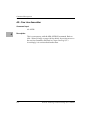
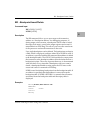
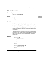
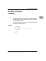
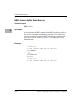
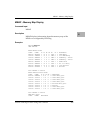
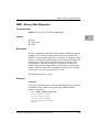
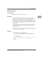
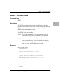
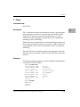
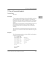
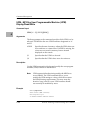
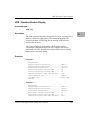
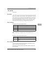
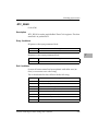
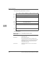
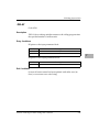
OF - Offset Registers Display/Modify
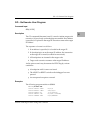
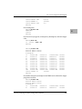
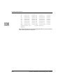
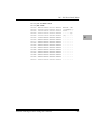
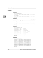
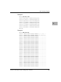
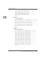
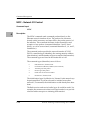
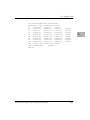
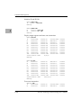
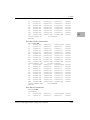
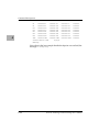
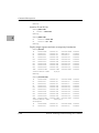
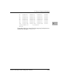
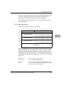
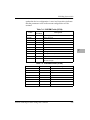
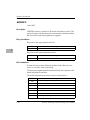
There are eight offset registers Z0-Z7, but only Z0-Z6 can be
changed. Z7 always has both base and top addresses set to 0. This
allows the automatic register function to be effectively disabled by
setting Z7 as the automatic register.
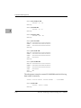
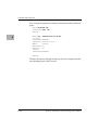
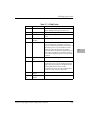
Each offset register has two values: base and top.
❏
Base is the absolute least address that is used for the range
declared by the offset register.
❏
Top address is the absolute greatest address that is used.
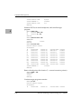
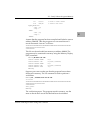
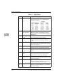
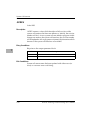
When entering the base and top, you may use either an
address/address format or an address/count format. If a count is
speciÞed, it refers to bytes. If the top address is omitted from the
range, then a count of 1MB is assumed. The top address must equal
or exceed the base address. Wrap-around is not permitted.
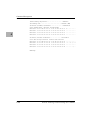
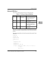
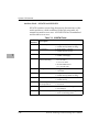
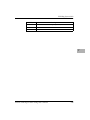
Offset Register Rules
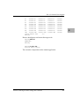
1. At power-up and cold start reset, Z7 is the automatic register.
2. At power-up and cold start reset, all offset registers have both
base and top addresses preset to 0. This effectively disables
them.
3. Z7 always has both base and top addresses set to 0, it cannot
be changed.
4. Any offset register can be set as the automatic register.
5. The automatic register is always added to every absolute
address argument of every EPPCBug command where there
is not an offset register explicitly called out.
6. There is always an automatic register. To disable the effect of
the automatic register, set Z7 as the automatic register. Note
that this is the default condition.
PowerPC EPPCBug Firmware Package UserÕs Manual
4-113
4