1
Debugging Package for
Motorola 68K CISC CPUs
User's Manual
(Part 1 of 2)
68KBUG1/D3
Notice
While reasonable efforts have been made to assure the accuracy of this document,
Motorola, Inc. assumes no liability resulting from any omissions in this document,
or from the use of the information obtained therein. Motorola reserves the right to
revise this document and to make changes from time to time in the content hereof
without obligation of Motorola to notify any person of such revision or changes.
No part of this material may be reproduced or copied in any tangible medium, or
stored in a retrieval system, or transmitted in any form, or by any means, radio,
electronic, mechanical, photocopying, recording or facsimile, or otherwise,
without the prior written permission of Motorola, Inc.
It is possible that this publication may contain reference to, or information about
Motorola products (machines and programs), programming, or services that are
not announced in your country. Such references or information must not be
construed to mean that Motorola intends to announce such Motorola products,
programming, or services in your country.
Restricted Rights Legend
If the documentation contained herein is supplied, directly or indirectly, to the U.S.
Government, the following notice shall apply unless otherwise agreed to in
writing by Motorola, Inc.
Use, duplication, or disclosure by the Government is subject to restrictions as set
forth in subparagraph (c)(1)(ii) of the Rights in Technical Data and Computer
Software clause at DFARS 252.227-7013.
Motorola, Inc.
Computer Group
2900 South Diablo Way
Tempe, Arizona 85282
Preface
The Debugging Package for Motorola 68K CISC CPUs User's Manual provides general
information for the onboard Þrmware package for all Motorola 68000 CISC CPU
and MPU VMEmodule boards.
This document is bound in two parts. Part 1 (68KBUG1/D3, this volume) contains
the Table of Contents and Chapters 1 through 3. Part 2 (68KBUG2/D3) contains
Chapters 4 and 5, Appendices A through I, and the Index.
This manual is intended for anyone who wants to design OEM systems, supply
additional capability to an existing compatible system, or work in a lab
environment for experimental purposes.
The following Þrmware packages and boards are covered in this manual:
MVME162
MVME172
MVME166
MVME167
MVME176
MVME177
162Bug
172Bug
166Bug
167Bug
176Bug
177Bug
The Þrmware packages are referred to as 16XBug in this manual. The boards are
referred to as MVME16X.
This manual describes the debugger, the debugger command set, the one-line
assembler/disassembler, and system calls. These functional elements are common
to all Þrmware packages.
Installation, start-up, diagnostics tests, and environmental parameters are
described in the diagnostic manuals for each of the Þrmware packages.
A basic knowledge of computers and digital logic is assumed.
Motorola and the Motorola symbol are registered trademarks of Motorola, Inc.
SYSTEM V/68 is a trademark of Motorola, Inc.
Timekeeper and Zeropower are trademarks of SGS-THOMSON Microelectronics.
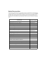
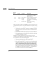
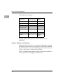
Related Documentation
The following publications are applicable to Motorola 68K CISC CPU debugging
packages and may provide additional helpful information. If not shipped with this
product, they may be purchased by contacting your local Motorola sales ofÞce.
Non-Motorola documents may be obtained from the sources listed following the
table.
Document Title
Motorola
Publication Number
M68040 Microprocessors User's Manual
M68040UM/AD
M68060 Microprocessors User's Manual
M68060UM/AD
MVME050 System Controller Module User's Manual
MVME050/D
MVME162 ProgrammerÕs Reference Guide
MVME162PG/D
MVME162FX ProgrammerÕs Reference Guide
MVME162LXPG/D
MVME162LX ProgrammerÕs Reference Guide
V162FXA/PG
MVME172 ProgrammerÕs Reference Guide
VME172A/PG
Single Board Computers Programmer's Reference Guide
VMESBCA1/PG and
VMESBCA2/PG
162BugDiagnostics UserÕs Manual
V162DIAA/UM
167Bug Debugging Package UserÕs Manual
MVME167BUG/D
172Bug Diagnostics UserÕs Manual
V172DIAA/UM
177Bug Diagnostics User's Manual
V177DIAA/UM
MVME320B VMEbus Disk Controller Module User's Manual
MVME320B/D
MVME323 ESDI Disk Controller User's Manual
MVME323/D
MVME327A VMEbus to SCSI Bus Adapter and
MVME717 Transition Module User's Manual
MVME327A/D
MVME327A Firmware User's Manual
MVME327AFW/D
MVME328 VMEbus Dual SCSI Host Adapter User's Manual
MVME328/D
MVME335 Serial and Parallel I/O Module User's Manual
MVME335/D
MVME350 Streaming Tape Controller VMEmodule User's Manual
MVME350/D
MVME350 IPC Firmware User's Guide
MVME350FW/D
MVME374 Multi-Protocol Ethernet Interface Module User's Manual MVME374/D
MVME376 Ethernet Communication Controller User's Manual
MVME376/D
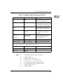
Note
Although not shown in the above list, each Motorola
Computer Group manual publication number is
suffixed with the revision level of the document, such
as Ò2Ó (the second revision of a manual); a supplement
bears the same number as a manual but has a suffix
such as "2A1" (the first supplement to the second
revision of the manual).
The following publications are available from the sources indicated.
ANSI Small Computer System Interface-2 (SCSI-2), Draft Document X3.131-198X,
Revision 10c; Global Engineering Documents, P.O. Box 19539, Irvine, CA 92714.
Versatile Backplane Bus: VMEbus, ANSI/IEEE Std. 1014-1987, The Institute of
Electrical and Electronics Engineers, Inc., 345 East 47th Street, New York, NY 10017
(VMEbus SpeciÞcation). This is also available as Microprocessor system bus for 1 to 4
byte data, IEC 821 BUS, Bureau Central de la Commission Electrotechnique
Internationale; 3, rue de VarembŽ, Geneva, Switzerland.
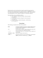
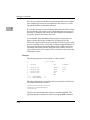
Manual Terminology
Throughout this manual, a convention has been maintained whereby data and
address parameters are preceded by a character which speciÞes the numeric
format as follows:
$
hexadecimal character
%
binary number
&
decimal number
Unless otherwise speciÞed, all address references are in hexadecimal throughout
this manual.
An asterisk (*) following the signal name for signals which are level signiÞcant
denotes that the signal is true or valid when the signal is low.
An asterisk (*) following the signal name for signals which are edge signiÞcant
denotes that the actions initiated by that signal occur on high to low transition.
In this manual, assertion and negation are used to specify forcing a signal to a
particular state. In particular, assertion and assert refer to a signal that is active or
true; negation and negate indicate a signal that is inactive or false. These terms are
used independently of the voltage level (high or low) that they represent.
Data and address sizes are deÞned as follows:
❏
A byte is eight bits, numbered 0 through 7, with bit 0 being the
least significant.
❏
A word is 16 bits, numbered 0 through 15, with bit 0 being the
least significant.
❏
A longword is 32 bits, numbered 0 through 31, with bit 0 being
the least significant.
Conventions
The following conventions are used in this document:
bold
is used for user input that you type just as it appears. Bold is also used
for commands, options and arguments to commands, and names of
programs, directories, and files.
italic
is used for names of variables to which you assign values. Italic is also
used for comments in screen displays and examples.
courier
is used for system output (e.g., screen displays, reports), examples, and
system prompts.
<RETURN> or <CR>
represents the carriage return or Enter key.
CTRL or ^
represents the Control key. Execute control characters by pressing the
CTRL key and the letter simultaneously, e.g., CTRL-d.
Safety Summary
Safety Depends On You
The following general safety precautions must be observed during all phases of operation, service, and
repair of this equipment. Failure to comply with these precautions or with speciÞc warnings elsewhere in
this manual violates safety standards of design, manufacture, and intended use of the equipment.
Motorola, Inc. assumes no liability for the customer's failure to comply with these requirements.
The safety precautions listed below represent warnings of certain dangers of which Motorola is aware. You,
as the user of the product, should follow these warnings and all other safety precautions necessary for the
safe operation of the equipment in your operating environment.
Ground the Instrument.
To minimize shock hazard, the equipment chassis and enclosure must be connected to an electrical ground.
The equipment is supplied with a three-conductor ac power cable. The power cable must be plugged into
an approved three-contact electrical outlet. The power jack and mating plug of the power cable meet
International Electrotechnical Commission (IEC) safety standards.
Do Not Operate in an Explosive Atmosphere.
Do not operate the equipment in the presence of ßammable gases or fumes. Operation of any electrical
equipment in such an environment constitutes a deÞnite safety hazard.
Keep Away From Live Circuits.
Operating personnel must not remove equipment covers. Only Factory Authorized Service Personnel or
other qualiÞed maintenance personnel may remove equipment covers for internal subassembly or
component replacement or any internal adjustment. Do not replace components with power cable
connected. Under certain conditions, dangerous voltages may exist even with the power cable removed. To
avoid injuries, always disconnect power and discharge circuits before touching them.
Do Not Service or Adjust Alone.
Do not attempt internal service or adjustment unless another person capable of rendering Þrst aid and
resuscitation is present.
Use Caution When Exposing or Handling the CRT.
Breakage of the Cathode-Ray Tube (CRT) causes a high-velocity scattering of glass fragments (implosion).
To prevent CRT implosion, avoid rough handling or jarring of the equipment. Handling of the CRT should
be done only by qualiÞed maintenance personnel using approved safety mask and gloves.
Do Not Substitute Parts or Modify Equipment.
Because of the danger of introducing additional hazards, do not install substitute parts or perform any
unauthorized modiÞcation of the equipment. Contact your local Motorola representative for service and
repair to ensure that safety features are maintained.
Dangerous Procedure Warnings.
Warnings, such as the example below, precede potentially dangerous procedures throughout this manual.
Instructions contained in the warnings must be followed. You should also employ all other safety
precautions which you deem necessary for the operation of the equipment in your operating environment.
!
WARNING
Dangerous voltages, capable of causing death, are
present in this equipment. Use extreme caution when
handling, testing, and adjusting.
The computer programs stored in the Read Only Memory of this device contain
material copyrighted by Motorola Inc., 1995, and may be used only under a license
such as those contained in MotorolaÕs software licenses.
The software described herein and the documentation appearing herein are
furnished under a license agreement and may be used and/or disclosed only in
accordance with the terms of the agreement.
The software and documentation are copyrighted materials. Making unauthorized
copies is prohibited by law. No part of the software or documentation may be
reproduced, transmitted, transcribed, stored in a retrieval system, or translated
into any language or computer language, in any form or by any means without the
prior written permission of Motorola, Inc.
Disclaimer of Warranty
Unless otherwise provided by written agreement with Motorola, Inc., the software
and the documentation are provided on an Òas isÓ basis and without warranty.
This disclaimer of warranty is in lieu of all warranties whether express, implied, or
statutory, including implied warranties of merchantability or Þtness for any
particular purpose.
!
WARNING
This equipment generates, uses, and can radiate
electro-magnetic energy. It may cause or be susceptible
to electro-magnetic interference (EMI) if not installed
and used in a cabinet with adequate EMI protection.
©Copyright Motorola 1997
All Rights Reserved
Printed in the United States of America
June 1997
Contents
Related Documentation 4
Introduction 1-1
Overview of M68000 Firmware 1-1
16XBug Implementation 1-3
General Installation and Start-up 1-3
Autoboot 1-5
ROMboot 1-7
Network Boot 1-11
Restarting the System 1-11
Reset 1-12
Abort 1-12
Break 1-13
SYSFAIL* Assertion/Negation 1-13
MPU Clock Speed Calculation 1-14
Memory Requirements 1-14
Terminal Input/Output Control 1-15
Disk I/O Support 1-16
Blocks Versus Sectors 1-16
Device Probe Function 1-17
Disk I/O via 16XBug Commands 1-17
IOI (Input/Output Inquiry) 1-17
IOP (Physical I/O to Disk) 1-18
IOT (I/O Teach) 1-18
IOC (I/O Control) 1-18
BO (Bootstrap Operating System) 1-18
BH (Bootstrap and Halt) 1-18
Disk I/O via 16XBug System Calls 1-18
Default 16XBug Controller and Device Parameters 1-20
Disk I/O Error Codes 1-20
Network I/O Support 1-21
Intel 82596 LAN Coprocessor Ethernet Driver 1-21
UDP/IP Protocol Modules 1-23
RARP/ARP Protocol Modules 1-23
BOOTP Protocol Module 1-23
TFTP Protocol Module 1-23
Network Boot Control Module 1-24
Network I/O Error Codes 1-24
Multiprocessor Support 1-24
Multiprocessor Control Register (MPCR) Method 1-24
GCSR Method 1-27
Diagnostic Facilities 1-27
Entering Debugger Command Lines 2-1
The Command Line 2-1
Command Arguments 2-2
exp - Expression as a Parameter 2-3
address - Address as a Parameter 2-4
Offset Registers 2-6
Port Numbers 2-8
Entering and Debugging Programs 2-8
Calling System Utilities from User Programs 2-9
Preserving the Debugger Operating Environment 2-9
16XBug Vector Table and Workspace 2-10
Hardware Functions 2-10
Exception Vectors Used by 16XBug 2-11
Using the 16XBug Target Vector Table 2-12
Creating a New Vector Table 2-13
Floating Point Support 2-15
Single Precision Real 2-16
Double Precision Real 2-16
ScientiÞc Notation 2-17
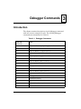
Introduction 3-1
AB/NOAB - Automatic Bootstrap Operating System/No Autoboot 3-5
AS - One Line Assembler 3-6
BC - Block of Memory Compare 3-7
BF - Block of Memory Fill 3-9
BH - Bootstrap Operating System and Halt 3-12
BI - Block of Memory Initialize 3-14
BM - Block of Memory Move 3-16
BO - Bootstrap Operating System 3-19
BR - Breakpoint Insert/Delete 3-23
BS - Block of Memory Search 3-25
BV - Block of Memory Verify 3-30
CM - Concurrent Mode 3-33
NOCM - No Concurrent Mode 3-36
CNFG - ConÞgure Board Information Block 3-37
CS - Checksum 3-40
DC - Data Conversion 3-42
DMA - DMA Block of Memory Move 3-44
DS - One Line Disassembler 3-50
DU - Dump S-Records 3-51
ECHO - Echo String 3-54
ENV - Set Environment to Bug/Operating System 3-56
Programming the VMEbus to Local Bus Map Decoders 3-57
ConÞguring ENV Parameters 3-58
Go Direct (Ignore Breakpoints) 3-59
GN - Go to Next Instruction 3-61
GO - Go Execute User Program 3-63
GO - Go to Temporary Breakpoint 3-66
HE - Help 3-69
IOC - I/O Control for Disk 3-72
IOI - I/O Inquiry 3-74
IOP - I/O Physical (Direct Disk Access) 3-76
IOT - I/O Teach for ConÞguring Disk Controller 3-82
IRQM - Interrupt Request Mask 3-91
LO - Load S-Records from Host 3-92
MA/NOMA - Macro DeÞne/Display/Delete 3-97
MAE - Macro Edit 3-100
MAL/NOMAL - Enable/Disable Macro Expansion Listing 3-102
MAW/MAR - Save/Load Macros 3-103
MD, MDS - Memory Display 3-106
MENU - System Menu 3-109
MM - Memory Modify 3-110
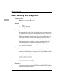
MMD - Memory Map Diagnostic 3-114
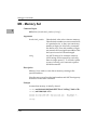
MS - Memory Set 3-116
MW - Memory Write 3-117
NAB - Automatic Network Boot Operating System 3-119
NBH - Network Boot Operating System and Halt 3-120
NBO - Network Boot Operating System 3-122
NIOC - Network I/O Control 3-126
NIOP - Network I/O Physical 3-131
NIOT - Network I/O Teach (ConÞguration) 3-133
NPING - Network Ping 3-139
OF - Offset Registers Display/Modify 3-141
PA/NOPA - Printer Attach/Detach 3-144
PF/NOPF - Port Format/Detach 3-146
Listing Current Port Assignments 3-147
ConÞguring a Port 3-147
Parameters ConÞgurable by Port Format 3-150
Assigning a New Port 3-151
NOPF Port Detach 3-152
PFLASH - Program FLASH Memory 3-153
PS - Put RTC into Power Save Mode for Storage 3-157
RB/NORB - ROMboot Enable/Disable 3-158
RD - Register Display 3-160
Ordering Sequence of MPU, DEF, FPC, and MMU Registers 3-162
Ordering Sequence of CPU Registers 3-163
MVME166/167/176/177 Registers 3-163
MVME162/MVME172 Registers 3-164
MMIEN, PIEN, and PIST Registers 3-164
MVME166/167/176/177 Registers 3-164
MVME162/MVME172 Registers 3-165
REMOTE - Connect Remote Modem to CSO 3-172
RESET - Cold/Warm Reset 3-173
RL - Read Loop 3-175
RM - Register Modify 3-176
RS - Register Set 3-179
SD - Switch Directories 3-180
SET - Set Time and Date 3-181
SFLASH - Switch FLASH 3-183
SYM - Symbol Table Attach 3-184
NOSYM - Symbol Table Detach 3-187
SYMS - Symbol Table Display/Search 3-188
T - Trace 3-190
TA - Terminal Attach 3-193
TC - Trace on Change of Control Flow 3-195
TIME - Display Time and Date 3-197
TM - Transparent Mode 3-199
TT - Trace to Temporary Breakpoint 3-201
VE - Verify S-Records Against Memory 3-204
VER - Revision/Version Display 3-208
WL - Write Loop 3-209
List of Figures
Network Boot Support Modules 1-22
List of Tables
Debugger Address Parameter Formats 2-5
Exception Vectors Used by 16XBug 2-11
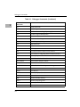
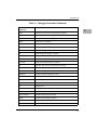
Debugger Commands 3-1
FLASH Memory Address and Range Alignment 3-154
xv
xvi
1General Information
1
Introduction
16XBug is a powerful evaluation and debugging tool for systems
built around the MVME16X CISC-based single-board computer
and embedded controller modules. Facilities are available for
loading and executing user programs under complete operator
control for system evaluation.
16XBug includes commands for display and modification of
memory, breakpoint and tracing capabilities, a powerful
assembler/disassembler useful for patching programs, and a selftest at power-up feature which verifies the integrity of the system.
Various 16XBug routines that handle I/O, data conversion, and
string functions are available to user programs through the TRAP
#15 system calls.
Note
167Bug is used in most examples of commands and
displays given in this manual. However, the
commands and displays apply to all 68K CISC
debugging packages, unless otherwise noted.
Overview of M68000 Firmware
The firmware packages for the M68000-based (68K) series of boards
and systems have a common genealogy. They achieve good
portability and comprehensibility by being written entirely in the
"C" programming language, except where forced to utilize
assembler functions.
1-1
1
General Information
16XBug consists of three parts:
1. A command-driven user-interactive software debugger,
described in Chapter 2 and hereafter referred to as "the
debugger" or "16XBug".
2. A command-driven diagnostic package for the specific CPU
board hardware, described in a separate board-specific
debugger manual and hereafter referred to as "the
diagnostics".
3. A user interface that accepts commands from the system
console terminal.
When using 16XBug, you will operate out of either the debugger
directory or the diagnostic directory.
❏
If you are in the debugger directory, the debugger prompt
"16X-Bug>" is displayed and you have all of the debugger
commands at your disposal.
❏
If you are in the diagnostic directory, the diagnostic prompt
"16X-Diag>" is displayed and you have all of the diagnostic
commands at your disposal as well as all of the debugger
commands.
You may switch between directories by using the Switch
Directories (SD) command (refer to Chapter 3), or may examine the
commands in the particular directory that you are currently in by
using the Help (HE) command (refer to Chapter 3).
Because 16XBug is command-driven, it performs its various
operations in response to user commands entered at the keyboard.
The flow of control in 16XBug is shown in the individual boardspecific debugger manuals. When you enter a command, 16XBug
executes the command and the prompt reappears. However, if you
enter a command that causes execution of user target code (e.g.,
"GO"), then control may or may not return to 16XBug, depending
on the outcome of the user program.
1-2
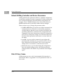
16XBug Implementation
If you have used one or more of Motorola's other debugging
packages, you will find the CISC 16XBug very similar. Some effort
has also been made to make the interactive commands more
consistent. For example, delimiters between commands and
arguments may now be commas or spaces interchangeably.
16XBug Implementation
16XBug is written largely in the "C" programming language,
providing benefits of portability and maintainability. Where
necessary, assembler has been used in the form of separately
compiled modules containing only assembler code - no mixed
language modules are used.
16XBug is contained on EPROM, PROM, or FLASH devices,
depending on which board is used. These memory devices provide
either 512KB or 1MB of storage. The memory provided is larger
than the space is occupied by the firmware because of the 32-bit
longword-oriented MC68040 and MC68060 memory bus
architecture. The executable code is checksummed at every poweron or reset firmware entry, and the result (which includes a precalculated checksum contained in the EPROM, PROM, and FLASH
devices), is tested for an expected zero.
Note
Do not modify the EPROM, PROM, and FLASH
devices unless re-checksum precautions are taken.
General Installation and Start-up
Even though the 16XBug memory devices are installed on the
MVME16X module, for 16XBug to operate properly with the
MVME16X, follow this general set-up procedure and the details
given in the board-specific debugger manual.
1-3
1
1
General Information
!
Caution
Inserting or removing modules while power is applied could
damage module components.
1. Turn all equipment power OFF. Refer to the individual board
installation manual and install/remove jumpers on headers
and/or set configuration switches as required for your
particular application.
2. Refer to the board installation manual and configure the
jumper or switch that enables/disables the system controller
function of the MVME16X.
3. Be sure that the 16XBug memory devices are installed in
proper sockets on the MVME16X module. Refer to the boardspecific debugger manual for details.
4. Refer to the set-up procedure for your particular chassis or
system for details concerning the installation of the
MVME16X.
5. Connect the terminal which is to be used as the 16XBug
system console to the default debug EIA-232-D port at the
proper location described in the MVME16X installation
manual or the 16XBug board-specific debugger manual. Set
up the terminal as follows:
Ð Eight bits per character
Ð One stop bit per character
Ð Parity disabled (no parity)
Ð Baud rate 9600 baud (default baud rate of MVME16X ports
at power-up)
After power-up, the baud rate of the debug port can be
reconfigured by using the Port Format (PF) command of the
16XBug debugger.
Note
1-4
In order for high-baud rate serial communication
between 16XBug and the terminal to work, the terminal
must do some form of handshaking. If the terminal
Autoboot
being used does not do hardware handshaking via the
CTS line, then it must do XON/XOFF handshaking. If
you get garbled messages and missing characters, then
you should check the terminal to make sure
XON/XOFF handshaking is enabled.
6. If you want to connect devices (such as a host computer
system and/or a serial printer) to the other EIA-232-D port(s),
connect the appropriate cables and configure the port(s) as
detailed in step 5 above. After power-up, this (these) port(s)
can be reconfigured by programming the MVME16X serial
interface chip, or by using the 16XBug PF command.
Note that some MVME16X modules contain parallel ports. To
use a parallel device, such as a printer, with such an
MVME16X module, connect it to the appropriate parallel port
per the installation manual for the MVME16X module.
However, with any MVME16X, you could add a module such
as the MVME335 to the system.
7. Power up the system. 16XBug executes some self-checks and
displays the debugger prompt "16X-Bug>" (if 16XBug is in
Board Mode). However, if the ENV command has put
16XBug in System Mode, the system performs a selftest and
tries to autoboot. Refer to the ENV and MENU commands in
Chapter 3, and to system operation in Appendix A.
If the confidence test fails, the test is aborted when the first
fault is encountered. If possible, an appropriate message is
displayed, and control then returns to the menu.
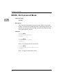
Autoboot
Autoboot is a software routine that is contained in the 16XBug
EPROM, PROM, or FLASH devices to provide an independent
mechanism for booting an operating system. This Autoboot routine
automatically scans for controllers and devices in a specified
sequence until a valid bootable device containing a boot media is
1-5
1
1
General Information
found or the list is exhausted. If a valid bootable device is found, a
boot from that device is started. The controller scanning sequence
goes from the lowest controller Logical Unit Number (LUN)
detected to the highest LUN detected. (Refer to Appendix E for
default LUNs.)
At power-up, Autoboot is enabled, and providing the drive and
controller numbers encountered are valid, the following message is
displayed upon the system console:
"Autoboot in progress... To abort hit <BREAK>"
Following this message there is a delay to allow you an opportunity
to abort the Autoboot process if you wish. Then the actual I/O is
begun: the program pointed to within the volume ID of the media
specified is loaded into RAM and control passed to it. If, however,
during this time you want to gain control without Autoboot, you
can press the <BREAK> key or the software ABORT or RESET
switches.
Autoboot is controlled by parameters contained in the ENV
command. These parameters allow the selection of specific boot
devices and files, and allow programming of the Boot delay. Refer
to the ENV command in Chapter 3 for more details.
!
Caution
Although streaming tape can be used to autoboot, the
same power supply must be connected to the streaming
tape drive, controller, and the MVME16X. At power-up,
the tape controller will position the streaming tape to
load point where the volume ID can correctly be read
and used.
If, however, the MVME16X loses power but the
controller does not, and the tape happens to be at load
point, the sequences of commands required (attach and
rewind) cannot be given to the controller and Autoboot
will not be successful.
1-6
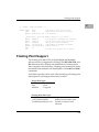
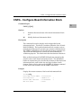
ROMboot
ROMboot
This function is configured/enabled by the Environment (ENV)
command and executed at power-up (optionally also at reset) or by
the RB command assuming there is valid code in the EPROM,
PROM, or FLASH devices (or optionally elsewhere on the module
or VMEbus) to support it. If ROMboot code is installed, a userwritten routine is given control (if the routine meets the format
requirements). One use of ROMboot might be resetting SYSFAIL*
on an unintelligent controller module. The NORB command
disables the function.
For a user's ROMboot module to gain control through the
ROMboot linkage, four requirements must be met:
1. Power must have just been applied (but the ENV command
can change this to also respond to any reset).
2. Your routine must be located within the MVME16X ROM
memory map (but the ENV command can change this to any
other portion of the onboard memory, or even offboard
VMEbus memory).
3. The ASCII string "BOOT" must be located within the
specified memory range.
4. Your routine must pass a checksum test, which ensures that
this routine was really intended to receive control at powerup.
To prepare a module for ROMboot, the Checksum (CS) command
must be used. When the module is ready it can be loaded into RAM,
and the checksum generated, installed, and verified with the CS
command. (Refer to the CS command description and examples in
Chapter 3.)
The format of the beginning of the routine is as follows:
1-7
1
1
General Information
Module
Offset
$00
Length
4 bytes
$04
$08
4 bytes
4 bytes
$0C
?
Contents
BOOT
Description
ASCII string indicating
possible routine; checksum
must be zero, too.
Entry Address Longword offset from "BOOT".
Routine
Longword, includes length
Length
from "BOOT" to and including
checksum.
Routine name ASCII string containing
routine name.
When you wish to make use of ROMboot, you do not have to fill a
complete memory device. Any partial amount is acceptable, as long
as:
1. The identifier string "BOOT" starts on a longword (EPROM
and Direct spaces) or 8KB (local RAM and VMEbus spaces)
boundary.
2. The ROMboot module size (in bytes) is evenly divisible by 2.
3. The length parameter (offset $8) reflects where the checksum
is, and the checksum is correct.
ROMboot searches predefined areas of the memory map for
possible routines and checks for the "BOOT" indicator. Two events
are of interest for any location being tested:
1. The map is searched for the ASCII string "BOOT".
2. If the ASCII string "BOOT" is found, it is still undetermined
whether the routine is meant to gain control at power-up or
reset. To verify that this is the case, the bytes starting from
"BOOT" through the end of the routine, excluding the two
byte checksum, are run through the Bug checksum algorithm.
If the result of the checksum is equal to the final two bytes of
the ROMboot module (the checksum), it is established that
the routine was meant to be used for ROMboot.
1-8
ROMboot
Under control of the ENV command, the sequence of searches is as
follows:
1. Search direct address for "BOOT".
2. Search complete ROM map.
3. Search local RAM, at all 8K byte boundaries starting at the
beginning of local RAM.
4. Search the VMEbus map (if so selected by the ENV
command) on all 8K byte boundaries starting at the end of the
onboard RAM. VMEbus address space is searched both
below (if the start address of local RAM is not located at 0)
and above local RAM up to the beginning of EPROM, PROM,
or FLASH memory space.
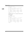
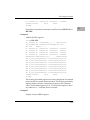
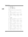
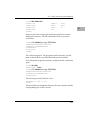
The example below performs the following:
1. Outputs a <CR><LF> sequence to the default output port.
2. Displays the date and time from the current cursor position.
3. Outputs two more <CR><LF> sequences to the default
output port.
4. Returns control to 167Bug.
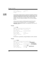
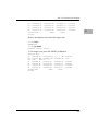
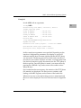
Sample ROMboot Routine
Module preparation including calculation of checksum:
The target code is first assembled and linked, leaving $00 in the
even and odd locations destined to contain the checksum.
Load the routine into RAM (with S-records via the LO command,
or from magnetic media using IOP).
Display the entire module (checksum bytes are at $00010024 and
$00010025).
167-Bug>md
10000 :c;l
1-9
1
1
General Information
00010000
00010010
00010020
424F4F54 00000010 00000026 54455354
4E4F0026 4E4F0052 4E4F0026 4E4F0026
4E4F0063 00000000 00000000 00000000
167-Bug>md 10010:5;di
00010010 4E4F0026 SYSCALL
00010014 4E4F0052 SYSCALL
00010018 4E4F0026 SYSCALL
0001001C 4E4F0026 SYSCALL
00010020 4E4F0063 SYSCALL
167-Bug>cs 10000:26/2;w
Effective address: 00010000
Effective count
Checksum: C226
.PCRLF
.RTC_DSP
.PCRLF
.PCRLF
.RETURN
BOOT.......&TEST
N0.&NO.RNO.&NO.&
NO.c............
Disassemble
executable
instructions.
Perform checksum on
locations $10000 through
$10025 (refer to the CS
command).
: &38
167-Bug>m 10024;w
00010024 0000? c226.
Insert checksum into bytes $10024, $10025.
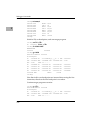
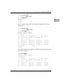
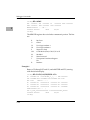
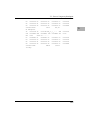
Again display the entire module (now with checksums).
167-Bug>md
00010000
00010010
00010020
10000 :c;l
424F4F54 00000010 00000026 54455354
4E4F0026 4E4F0052 4E4F0026 4E4F0026
4E4F0063 C2260000 00000000 00000000
BOOT.......&TEST
NO.&NO.RNO.&NO.&
NO.c.&..........
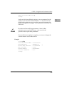
Verify the functionality of your ROMboot module by executing the
RB command. (The "VERBOSE" option reports the progress of the
search.)
167-Bug>rb;v
ROMboot in progress... To abort hit <BREAK>
Direct Adr: FFC00000 FFC00000: Searching for ROMboot Module at: FFC00000
ROM
: FFC00000 FFC7FFFC: Searching for ROMboot Module at: FFC7E000
Local RAM : 00000000 00FFFFFC: Searching for ROMboot Module at: 00010000
Executing ROMboot Module "TEST" at 00010000
FRI SEP 15 11:50:21.00 1989
167-Bug>
1-10
The ROMboot module is now ready for use.
Network Boot
Network Boot
Network Auto Boot is a software routine contained in the 16XBug
EPROM, PROM, or FLASH devices that provides a mechanism for
booting an operating system using a network (local Ethernet
interface) as the boot device. The Network Auto Boot routine
automatically scans for controllers and devices in a specified
sequence until a valid bootable device containing a boot media is
found or the list is exhausted. If a valid bootable device is found, a
boot from that device is started. The controller scanning sequence
goes from the lowest controller Logical Unit Number (LUN)
detected to the highest LUN detected. (Refer to Appendix G for
default LUNs.)
At power-up, Network Boot is enabled, and providing the drive
and controller numbers encountered are valid, the following
message is displayed upon the system console:
"Network Boot in progress... To abort hit <BREAK>"
Following this message there is a delay to allow you to abort the
Auto Boot process if you wish. Then the actual I/O is begun: the
program pointed to within the volume ID of the media specified is
loaded into RAM and control passed to it. If, however, during this
time you want to gain control without Network Boot, you can press
the <BREAK> key or the software ABORT or RESET switches.
Network Auto Boot is controlled by parameters contained in the
NIOT and ENV commands. These parameters allow the selection
of specific boot devices, systems, and files, and allow programming
of the Boot delay. Refer to the NIOT and ENV commands in
Chapter 3 for more details.
Restarting the System
You can initialize the system to a known state in three different
ways: reset, abort, and break. Each has characteristics which make
it more appropriate than the others in certain situations.
1-11
1
1
General Information
The debugger has a special feature upon a reset condition. This
feature is activated by depressing the RESET and ABORT switches
at the same time. This feature instructs the debugger to use the
default setup/operation parameters in ROM versus your
setup/operation parameters in NVRAM. This feature can be used
in the event your setup/operation parameters are corrupted or do
not meet a sanity check. Refer to the ENV command for the ROM
defaults.
Reset
Pressing and releasing the MVME16X front panel RESET switch
initiates a system reset. COLD and WARM reset modes are
available. By default, 16XBug is in COLD mode (refer to the RESET
command description in Chapter 3). During COLD reset, a total
system initialization takes place, as if the MVME16X had just been
powered up. All static variables (including disk device and
controller parameters) are restored to their default states. The
breakpoint table and offset registers are cleared. The target registers
are invalidated. Input and output character queues are cleared.
Onboard devices (timer, serial ports, etc.) are reset, and the first two
serial ports are reconfigured to their default state.
During WARM reset, the 16XBug variables and tables are
preserved, as well as the target state registers and breakpoints.
Reset must be used if the processor ever halts, or if the 16XBug
environment is ever lost (vector table is destroyed, stack corrupted,
etc.).
Abort
Pressing and releasing the ABORT switch on the MVME16X front
panel generates a local board condition which interrupts the
processor, if enabled. Whenever abort is invoked while executing a
user program (running target code), a ÒsnapshotÓ of the processor
state is captured and stored in the target registers. The contents of
the registers are displayed on the screen. Any breakpoints installed
1-12
Restarting the System
in your code are removed and the breakpoint table remains intact.
Control is returned to the debugger. Use the debuggerÕs RD; e
command to display the contents of the target registers after
pressing ABORT when not executing a user program.
Abort is most appropriate when terminating a user program that is
being debugged. Abort should be used to regain control if the
program gets caught in a loop, etc. The target PC, register contents,
etc., reflecting the machine state at the time the ABORT switch was
pressed, help to pinpoint the malfunction.
Break
A ÒBreakÓ is generated by pressing and releasing the BREAK key
on the terminal keyboard. Break does not generate an interrupt. The
only time break is recognized is when characters are sent or
received by the console port. Break removes any breakpoints in
your code and keeps the breakpoint table intact. Break also takes a
snapshot of the machine state if the function was entered using
SYSCALL. This machine state is then accessible to you for
diagnostic purposes.
Many times it may be desirable to terminate a debugger command
prior to its completion; for example, during the display of a large
block of memory. Break allows you to terminate the command.
SYSFAIL* Assertion/Negation
Upon a reset/powerup condition the debugger asserts the VMEbus
SYSFAIL* line (refer to the VMEbus specification). SYSFAIL* stays
asserted if any of the following has occurred:
❏
Confidence test failure
❏
NVRAM checksum error
❏
NVRAM low battery condition
❏
Local memory configuration status
❏
Self test (if system mode) has completed with error
❏
MPU clock speed calculation failure
1-13
1
1
General Information
After debugger initialization is done and none of the above
situations have occurred, the SYSFAIL* line is negated. This
indicates to the user or VMEbus masters the state of the debugger.
In a multi-computer configuration, other VMEbus masters could
view the pertinent control and status registers to determine which
CPU is asserting SYSFAIL*. SYSFAIL* assertion/negation is also
affected by the ENV command. Refer to Chapter 3.
MPU Clock Speed Calculation
The clock speed of the microprocessor is calculated and checked
against a user definable parameter housed in NVRAM (refer to the
CNFG command). If the check fails, a warning message is
displayed. The calculated clock speed is also checked against
known clock speeds and tolerances.
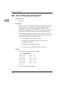
Memory Requirements
The program portion of 16XBug is several hundred KB of code,
consisting of download, debugger, and diagnostic packages and
contained entirely in the EPROM, PROM, or FLASH devices. The
exact size of this code and mapped starting location of the memory
devices on the MVME16X are board-dependent and are given in the
board-specific debugger manuals for each particular board series.
16XBug requires a minimum of 64KB of contiguous read/write
memory to operate.
The ENV command controls where this block of memory is located.
Regardless of where the onboard RAM is located, the first 64KB is
used for 16XBug stack and static variable space and the rest is
reserved as user space. Whenever the MVME16X is reset, the target
PC is initialized to the address corresponding to the beginning of
the user space, and the target stack pointers are initialized to
addresses within the user space, with the target Interrupt Stack
Pointer (ISP) set to the top of the user space.
1-14
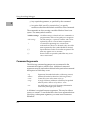
Terminal Input/Output Control
Terminal Input/Output Control
When entering a command at the prompt, the following control
codes may be entered for limited command line editing.
Note
The presence of the caret ( ^ ) before a character
indicates that the Control (CTRL) key must be held
down while striking the character key.
^X
Cancel line
^H
Backspace
<DEL>
^D
Delete or
rubout
Redisplay
^A
Repeat
The cursor is backspaced to the beginning
of the line. If the terminal port is conÞgured
with the hardcopy or TTY option (refer to
PF command), then a carriage return and
line feed is issued along with another
prompt.
The cursor is moved back one position. The
character at the new cursor position is
erased. If the hardcopy option is selected, a
"/" character is typed along with the deleted
character.
Performs the same function as ^H.
The entire command line as entered so far
is redisplayed on the following line.
Repeats the previous line. This happens
only at the command line. The last line
entered is redisplayed but not executed.
The cursor is positioned at the end of the
line. You may enter the line as is or you can
add more characters to it. You can edit the
line by backspacing and typing over old
characters.
When observing output from any 16XBug command, the XON and
XOFF characters which are in effect for the terminal port may be
entered to control the output, if the XON/XOFF protocol is enabled
1-15
1
1
General Information
(default). These characters are initialized to ^S and ^Q respectively
by 16XBug, but you may change them with the PF command. In the
initialized (default) mode, operation is as follows:
^S
^Q
Wait
Resume
Console output is halted.
Console output is resumed.
Disk I/O Support
16XBug can initiate disk input/output by communicating with
intelligent disk controller modules over the VMEbus. Disk support
facilities built into 16XBug consist of command-level disk
operations, disk I/O system calls (only via one of the TRAP #15
instructions - refer to Chapter 5) for use by user programs, and
defined data structures for disk parameters.
Parameters such as the address where the module is mapped and
the type and number of devices attached to the controller module
are kept in tables by 16XBug. Default values for these parameters
are assigned at power-up and cold-start reset, but may be altered as
described in the section on default parameters, later in this chapter.
Appendix E contains a list of the controllers presently supported, as
well as a list of the default configurations for each controller.
Blocks Versus Sectors
The logical block defines the unit of information for disk devices. A
disk is viewed by 16XBug as a storage area divided into logical
blocks. By default, the logical block size is set to 256 bytes for every
block device in the system. The block size can be changed on a per
device basis with the IOT command.
The sector defines the unit of information for the media itself, as
viewed by the controller. The sector size varies for different
controllers, and the value for a specific device can be displayed and
changed with the IOT command.
1-16
Disk I/O Support
When a disk transfer is requested, the start and size of the transfer
is specified in blocks. 16XBug translates this into an equivalent
sector specification, which is then passed on to the controller to
initiate the transfer. If the conversion from blocks to sectors yields
a fractional sector count, an error is returned and no data is
transferred.
Device Probe Function
A device probe with entry into the device descriptor table is done
whenever a specified device is accessed; i.e., when system calls
.DSKRD, .DSKWR, .DSKCFIG, .DSKFMT, and .DSKCTRL, and
debugger commands BH, BO, IOC, IOP, IOT, MAR, and MAW
are used.
The device probe mechanism utilizes the SCSI commands "Inquiry"
and "Mode Sense". If the specified controller is non-SCSI, the probe
simply returns a status of "device present and unknown". The
device probe makes an entry into the device descriptor table with
the pertinent data. After an entry has been made, the next time a
probe is done it simply returns with "device present" status (pointer
to the device descriptor).
Disk I/O via 16XBug Commands
These following 16XBug commands are provided for disk I/O.
Detailed instructions for their use are found in Chapter 3. When a
command is issued to a particular Controller Logical Unit Number
(CLUN) and Device Logical Unit Number (DLUN), these LUNs are
remembered by 16XBug so that the next disk command defaults to
use the same controller and device.
IOI (Input/Output Inquiry)
This command is used to probe the system for all possible
CLUN/DLUN combinations and display inquiry data for devices
which support it. The device descriptor table only has space for 16
device descriptors; with the IOI command, you can view the table
and clear it if necessary.
1-17
1
1
General Information
IOP (Physical I/O to Disk)
IOP allows you to read or write blocks of data, or to format the
specified device in a certain way. IOP creates a command packet
from the arguments you have specified, and then invokes the
proper system call function to carry out the operation.
IOT (I/O Teach)
IOT allows you to change any configurable parameters and
attributes of the device. In addition, it allows you to see the
controllers available in the system.
IOC (I/O Control)
IOC allows you to send command packets as defined by the
particular controller directly. IOC can also be used to look at the
resultant device packet after using the IOP command.
BO (Bootstrap Operating System)
BO reads an operating system or control program from the
specified device into memory, and then transfers control to it.
BH (Bootstrap and Halt)
BH reads an operating system or control program from a specified
device into memory, and then returns control to 16XBug. It is used
as a debugging tool.
Disk I/O via 16XBug System Calls
All operations that actually access the disk are done directly or
indirectly by 16XBug TRAP #15 system calls. (The command-level
disk operations provide a convenient way of using these system
calls without writing and executing a program.)
The following system calls are provided to allow user programs to
do disk I/O:
1-18
Disk I/O Support
.DSKRD
Disk read. System call to read blocks from a disk into
memory.
.DSKWR
Disk write. System call to write blocks from memory
onto a disk.
.DSKCFIG
Disk conÞgure. This function allows you to change the
conÞguration of the speciÞed device.
.DSKFMT
Disk format. This function allows you to send a format
command to the speciÞed device.
.DSKCTRL
Disk control. This function is used to implement any
special device control functions that cannot be
accommodated easily with any of the other disk
functions.
Refer to Chapter 5 for information on using these and other system
calls.
To perform a disk operation, 16XBug must eventually present a
particular disk controller module with a controller command
packet which has been especially prepared for that type of
controller module. (This is accomplished in the respective
controller driver module.) A command packet for one type of
controller module usually does not have the same format as a
command packet for a different type of module. The system call
facilities which do disk I/O accept a generalized (controllerindependent) packet format as an argument, and translate it into a
controller-specific packet, which is then sent to the specified device.
Refer to the system call descriptions in Chapter 5 for details on the
format and construction of these standardized ÒuserÓ packets.
The packets which a controller module expects to be given vary
from controller to controller. The disk driver module for the
particular hardware module (board) must take the standardized
packet given to a trap function and create a new packet which is
specifically tailored for the disk drive controller it is sent to. Refer
to documentation on the particular controller module for the
format of its packets, and for using the IOC command.
1-19
1
1
General Information
Default 16XBug Controller and Device Parameters
16XBug initializes the parameter tables for a default configuration
of controllers and devices (refer to Appendix E). If the system needs
to be configured differently than this default configuration (for
example, to use a 70MB Winchester drive where the default is a
40MB Winchester drive), then these tables must be changed.
There are three ways to change the parameter tables:
❏
Use BO or BH. When you invoke one of these commands, the
configuration area of the disk is read and the parameters
corresponding to that device are rewritten according to the
parameter information contained in the configuration area.
(Appendix D has more information on the disk configuration
area.) This is a temporary change. If a cold-start reset occurs,
then the default parameter information is written back into
the tables.
❏
Use IOT. You can use this command to reconfigure the
parameter table manually for any controller and/or device
that is different from the default. This is also a temporary
change and is overwritten if a cold-start reset occurs.
❏
Obtain the source. You can then change the configuration
files and rebuild 16XBug so that it has different defaults.
Changes made to the defaults are permanent until changed
again.
Disk I/O Error Codes
16XBug returns an error code if an attempted disk operation is
unsuccessful. Refer to Appendix F for an explanation of disk I/O
error codes.
1-20
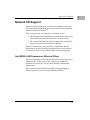
Network I/O Support
Network I/O Support
The Network Boot Firmware provides the capability to boot the
CPU through the ROM debugger using a network (local Ethernet
interface) as the boot device.
The booting process is executed in two distinct phases.
❏
The first phase allows the diskless remote node to discover its
network identify and the name of the file to be booted.
❏
The second phase has the diskless remote node reading the
boot file across the network into its memory.
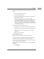
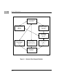
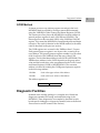
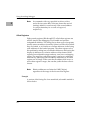
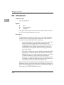
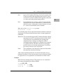
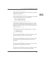
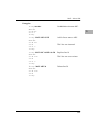
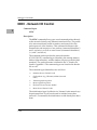
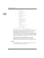
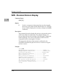
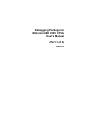
Figure 1-1 depicts the various modules (capabilities) and the
dependencies of these modules that support the overall network
boot function. They are described in the following paragraphs.
Intel 82596 LAN Coprocessor Ethernet Driver
This driver manages/surrounds the Intel 82596 LAN Coprocessor.
Management is in the scope of the reception of packets, the
transmission of packets, receive buffer flushing, and interface
initialization.
This module ensures that the packaging and unpackaging of
Ethernet packets is done correctly in the Boot PROM.
1-21
1
1
General Information
Boot Control Module
(Two phases)
Bootstrap Protocol
(BOOTP)
RFC 951
Trivial File Transfer
Protocol (TFTP)
RFC 783
User Datagram
Protocol (UDP)
RFC 768
Address Resolution
Protocol (ARP)
RFC 826
Reverse Address
Resolution Protocol
(RARP) - RFC 903
Internet Protocol
(IP)
RFC 791
Ethernet Driver
Intel 82596
1259 9312
Figure 1-1. Network Boot Support Modules
1-22
Network I/O Support
UDP/IP Protocol Modules
The Internet Protocol (IP) is designed for use in interconnected
systems of packet-switched computer communication networks.
The Internet protocol provides for transmitting of blocks of data
called datagrams (hence User Datagram Protocol, or UDP) from
sources to destinations, where sources and destinations are hosts
identified by fixed length addresses.
The UDP/IP protocols are necessary for the TFTP and BOOTP
protocols; TFTP and BOOTP require a UDP/IP connection.
RARP/ARP Protocol Modules
The Reverse Address Resolution Protocol (RARP) basically consists
of an identity-less node broadcasting a "whoami" packet onto the
Ethernet, and waiting for an answer. The RARP server fills an
Ethernet reply packet up with the target's Internet Address and
sends it.
The Address Resolution Protocol (ARP) basically provides a
method of converting protocol addresses (e.g., IP addresses) to
local area network addresses (e.g., Ethernet addresses). The RARP
protocol module supports systems which do not support the
BOOTP protocol (next paragraph).
BOOTP Protocol Module
The Bootstrap Protocol (BOOTP) basically allows a diskless client
machine to discover its own IP address, the address of a server host,
and the name of a file to be loaded into memory and executed.
TFTP Protocol Module
The Trivial File Transfer Protocol (TFTP) is a simple protocol to
transfer files. It is implemented on top of the Internet User
Datagram Protocol (UDP or Datagram) so it may be used to move
1-23
1
1
General Information
files between machines on different networks implementing UDP.
The only thing it can do is read and write files from/to a remote
server.
Network Boot Control Module
The "control" capability of the Network Boot Control Module ties
together all the modules (capabilities) and determines the booting
sequence. The booting sequence has two phases: the first, labeled
"address determination and bootfile selection", uses RARP/BOOTP
and the second, labeled "file transfer", uses TFTP.
Network I/O Error Codes
16XBug returns an error code if an attempted network operation is
unsuccessful. Refer to Appendix H for an explanation of network
I/O error codes.
Multiprocessor Support
The MVME16X dual-port RAM feature makes the shared RAM
available to remote processors as well as to the local processor. You
can access it by either the MPCR or GCSR method, which are
described in the next subsections. Either method can be enabled or
disabled by the ENV command as its Remote Start Switch Method.
Multiprocessor Control Register (MPCR) Method
A remote processor can initiate program execution in the local
MVME16X dual-port RAM by issuing a remote GO command
using the Multiprocessor Control Register (MPCR). The MPCR,
located at shared RAM location of $800 offset from the base address
1-24
Multiprocessor Support
the debugger loads it at, contains one of two longwords used to
control communication between processors. Organization of the
MPCR contents is:
$800
*
N/A N/A N/A (MPCR)
The status codes stored in the MPCR are of two types:
❏
Status returned (from the monitor)
❏
Status set (by the bus master)
The status codes that may be returned from the monitor are:
Hex
ASCII
0
E
(Hex 00)
(Hex 45)
ASCII
P
(Hex 50)
ASCII
R
(Hex 52)
Wait. Initialization not yet complete.
Code pointed to by the MPAR address
is executing.
Program FLASH Memory. The MPAR
is set to the address of the FLASH
memory program control packet.
Ready. The Þrmware monitor is
watching for a change.
You can only program FLASH memory by the MPCR method. See
the .PFLASH system call for a description of the FLASH memory
program control packet structure.
The status codes that may be set by the bus master are:
ASCII
G
(Hex 47)
ASCII
B
(Hex 42)
Use Go Direct (GD) logic specifying
the MPAR address.
Install breakpoints using the Go (G)
logic.
The Multiprocessor Address Register (MPAR), located in shared
RAM location of $804 offset from the base address the debugger
loads it at, contains the second of two longwords used to control
1-25
1
1
General Information
communication between processors. The MPAR contents specify
the address at which execution for the remote processor is to begin
if the MPCR contains a G or B. The MPAR is organized as follows:
$804
*
*
*
*
(MPAR)
At power-up, the debug monitor self-test routines initialize RAM,
including the memory locations used for multi-processor support
($800 through $807).
The MPCR contains $00 at power-up, indicating that initialization
is not yet complete. As the initialization proceeds, the execution
path comes to the "prompt" routine. Before sending the prompt,
this routine places an R in the MPCR to indicate that initialization
is complete. Then the prompt is sent.
If no terminal is connected to the port, the MPCR is still polled to
see whether an external processor requires control to be passed to
the dual-port RAM. If a terminal does respond, the MPCR is polled
for the same purpose while the serial port is being polled for user
input.
An ASCII G placed in the MPCR by a remote processor requests a
Go Direct type of transfer; an ASCII B indicates that breakpoints are
to be armed before control is transferred (like the GO command).
In either sequence, an E is placed in the MPCR to indicate that
execution is underway just before control is passed to RAM. (Any
remote processor could examine the MPCR contents.)
If the code being executed in dual-port RAM is to reenter the debug
monitor, a TRAP #15 call using function $0063 (SYSCALL
.RETURN) returns control to the monitor with a new display
prompt. Note that every time the debug monitor returns to the
prompt, an R is moved into the MPCR to indicate that control can
be transferred once again to a specified RAM location.
1-26
Diagnostic Facilities
GCSR Method
A remote processor can initiate program execution in the local
MVME16X dual-port RAM by issuing a remote GO command
using the VMEchip2 Global Control and Status Registers (GCSR).
The remote processor places the MVME16X execution address in
general purpose registers 0 and 1 (GPCSR0 and GPCSR1). The
remote processor then sets bit 8 (SIG0) of the VMEchip2 LM/SIG
register. This causes the MVME16X to install breakpoints and begin
execution. The result is identical to the MPCR method (with status
code B) described in the previous section.
The GCSR registers are accessed in the VMEbus short I/O space.
Each general purpose register is two bytes wide, occurring at an
even address. The general purpose register number 0 is at an offset
of $8 (local bus) or $4 (VMEbus) from the start of the GCSR
registers. The local bus base address for the GCSR is $FFF40100. The
VMEbus base address for the GCSR depends on the group select
value and the board select value programmed in the Local Control
and Status Registers (LCSR) of the MVME16X. The execution
address is formed by reading the GCSR general purpose registers
in the following manner:
GPCSR0
GPCSR1
Used as the upper 16 bits of the address
Used as the lower 16 bits of the address
The address appears as:
GPCSR0
GPCSR1
Diagnostic Facilities
Included in the 16XBug package is a complete set of hardware
diagnostics intended for testing and troubleshooting of the
MVME16X. These diagnostics are completely described in each
board-specific debugger or diagnostics manual (refer to the Related
Documentation section located in the Preface).
1-27
1
1
General Information
In order to use the diagnostics, you must switch directories to the
diagnostic directory. If you are in the debugger directory, you can
switch to the diagnostic directory by entering the debugger
command Switch Directories (SD). The diagnostic prompt ("16XDiag>") should appear. Refer to the board-specific debugger manual
for complete descriptions of the diagnostic routines available and
instructions on how to invoke them.
Note that some diagnostics depend on restart defaults that are set
up only in a particular restart mode. Refer to the documentation on
a particular diagnostic for the correct mode.
1-28
2Using the 16XBug Debugger
2
Entering Debugger Command Lines
16XBug is command-driven and performs its various operations in
response to user commands entered at the keyboard. When the
debugger prompt (16X-Bug>) appears on the terminal screen, then
the debugger is ready to accept commands.
As the command line is entered, it is stored in an internal buffer.
Execution begins only after the carriage return is entered, so that
you can correct entry errors, if necessary, using the control
characters described in Chapter 1.
When a command is entered, the debugger executes the command
and the prompt reappears. However, if the command entered
causes execution of user target code, for example GO, then control
may or may not return to the debugger, depending on what the
user program does. For example, if a breakpoint has been specified,
then control returns to the debugger when the breakpoint is
encountered during execution of the user program. Alternately, the
user program could return to the debugger by means of the TRAP
#15 function ".RETURN" (described in Chapter 5). For more about
this, refer to the descriptions in Chapter 3 for the GD, GT, and GO
commands.
The Command Line
In general, a debugger command is made up of the following parts:
❏
The command identifier (e.g., MD or md for the Memory
Display command). Note that either upper- or lowercase is
allowed.
❏
A port number, if the command is set up to work with more
than one port.
❏
At least one intervening space before the first argument.
2-1
Using the 16XBug Debugger
2
❏
Any required arguments, as specified by the command.
❏
An option field, set off by a semicolon (;), to specify
conditions other than the default conditions of the command.
The commands are shown using a modified Backus-Naur form
syntax. The metasymbols used are:
boldface strings
italic strings
|
[]
{}
A boldface string is a literal such as a command or a
program name, and is to be typed just as it appears.
An italic string is a "syntactic variableÓ and is to be
replaced by one of a class of items it represents.
A vertical bar separating two or more items
indicates that a choice is to be made; only one of the
items separated by this symbol should be selected.
Square brackets enclose an item that is optional. The
item may appear zero or one time.
Braces enclose an optional symbol that may occur
zero or more times.
Command Arguments
The following command arguments are encountered in the
command descriptions which follow. Additional command
arguments may be used and are defined in the particular command
description in which they occur.
exp
address
count
range
Expression (described in detail in a following section).
Address (described in detail in a following section).
Count; the syntax is the same as for exp.
A range of memory addresses which may be speciÞed
either by address address or by address : count.
text
An ASCII string of up to 255 characters, delimited at
each end by the single quote mark (').
A delimiter is required between arguments. This may be either a
space or a comma. To use the default value for an argument before
specifying a subsequent argument, you must insert commas as
delimiters.
2-2
Entering Debugger Command Lines
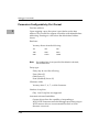
exp - Expression as a Parameter
2
An expression (exp) can be one or more numeric values separated
by the arithmetic operators: plus (+), minus (-), multiplied by (*),
divided by (/), logical AND (&), shift left (<<), or shift right (>>).
Numeric values may be expressed in either hexadecimal, decimal,
octal, or binary by immediately preceding them with the proper
base identifier.
Data Type
Base
IdentiÞer
Examples
Integer
Hexadecimal
$
$FFFFFFFF
Integer
Decimal
&
&1974, &10-&4
Integer
Octal
@
@456
Integer
Binary
%
%1000110
If no base identifier is specified, then the numeric value is assumed
to be hexadecimal.
A numeric value may also be expressed as a string literal of up to
four characters. The string literal must begin and end with the
single quote mark ('). The numeric value is interpreted as the
concatenation of the ASCII values of the characters. This value is
right-justified, as any other numeric value would be.
String Literal
Numeric Value
(In Hexadecimal)
'A'
41
'ABC'
414243
'TEST'
54455354
Evaluation of an expression is always from left to right unless
parentheses are used to group part of the expression. There is no
operator precedence. Subexpressions within parentheses are
evaluated first. Nested parenthetical subexpressions are evaluated
from the inside out.
2-3
Using the 16XBug Debugger
Valid expression examples:
2
Expression
Result
(In Hexadecimal)
FF0011
FF0011
45+99
DE
&45+&99
90
@35+@67+@10
5C
%10011110+%100
1
A7
88<<4
880
shift left
AA&F0
A0
logical
AND
Notes
The total value of the expression must be between 0 and
$FFFFFFFF.
address - Address as a Parameter
Many commands use address as a parameter. The syntax accepted
by 16XBug is similar to the one accepted by the MC68040/MC68040
one-line assembler. All control addressing modes are allowed. An
"address + offset register" mode is also provided.
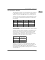
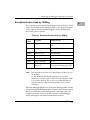
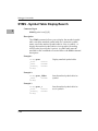
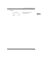
Table 2-1 summarizes the address formats which are acceptable for
address parameters in debugger command lines.
2-4
Entering Debugger Command Lines
Table 2-1. Debugger Address Parameter Formats
2
Format
Example
Description
N
140
Absolute address+contents of
automatic offset register.
N+Rn
130+R5
Absolute address+contents of
the speciÞed offset register (not
an assembler-accepted syntax).
(An)
(A1)
Address register indirect (also
post-increment, predecrement)
(d,An)
or
d(An)
(120,A1)
120(A1)
Address register indirect with
dis- placement (two formats
accepted).
(d,An,Xn)
or
d(An,Xn)
(&120,A1,D2)
&120(A1,D2)
Address register indirect with
index and displacement (two
formats accepted).
([bd,An,Xn],od)
([C,A2,A3],&100)
Memory indirect preindexed.
([bd,An],Xn,od)
([12,A3],D2,&10)
Memory indirect postindexed.
For the memory indirect modes, Þelds can be omitted.
For example, three of many permutations are as follows:
([,An],od)
([,A1],4)
([bd])
([FC1E])
([bd,,Xn])
([8,,D2])
Notes
N
An
Xn
d
bd
od
n
Rn
Ñ
Ñ
Ñ
Ñ
Ñ
Ñ
Ñ
Ñ
Absolute address (any valid expression).
Address register n.
Index register n (An or Dn).
Displacement (any valid expression).
Base displacement (any valid expression).
Outer displacement (any valid expression).
Register number (0 to 7).
Offset register n.
2-5
Using the 16XBug Debugger
Note
2
In commands with range specified as address address,
and with size option W or L chosen, data at the second
(ending) address is acted on only if the second address
is a proper boundary for a word or longword,
respectively.
Offset Registers
Eight pseudo-registers (R0 through R7) called offset registers are
used to simplify the debugging of relocatable and positionindependent modules. The listing files in these types of programs
usually start at an address (normally 0) that is not the one at which
they are loaded, so it is harder to correlate addresses in the listing
with addresses in the loaded program. The offset registers solve
this problem by taking into account this difference and forcing the
display of addresses in a relative address+offset format. Offset
registers have adjustable ranges and may even have overlapping
ranges. The range for each offset register is set by two addresses:
base and top. Specifying the base and top addresses for an offset
register sets its range. In the event that an address falls in two or
more offset registers' ranges, the one that yields the least offset is
chosen.
Note
Relative addresses are limited to 1MB (5 digits),
regardless of the range of the closest offset register.
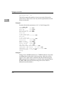
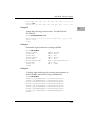
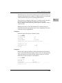
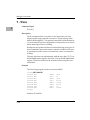
Example
A portion of the listing file of an assembled, relocatable module is
shown below:
2-6
Entering Debugger Command Lines
1
2
3
4
5
6
7
8
9
10
11
12
13
14
******
******
2
0
0
0
0
0
0
0
0
00000000
00000004
00000006
00000008
0000000A
0000000C
00000010
00000014
48E78080
4280
1018
5340
12D8
51C8FFFC
4CDF0101
4E75
*
* MOVE STRING SUBROUTINE
*
MOVESTR MOVEM.L D0/A0,—(A7)
CLR.L
D0
MOVE.B
(A0)+,D0
SUBQ.W
#1,D0
LOOP
MOVE.B
(A0)+,(A1)+
MOVS
DBRA
D0,LOOP
MOVEM.L (A7)+,D0/A0
RTS
END
TOTAL ERRORS
TOTAL WARNINGS
0——
0——
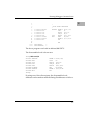
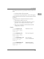
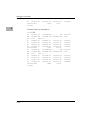
The above program was loaded at address $0001327C.
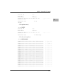
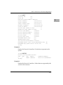
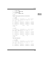
The disassembled code is shown next:
167Bug>MD 1327C;DI
0001327C
00013280
00013282
00013284
00013286
00013288
0001328C
00013290
167Bug>
48E78080
4280
1018
5340
12D8
51C8FFFC
4CDF0101
4E75
MOVEM.L
CLR.L
MOVE.B
SUBQ.W
MOVE.B
DBF
MOVEM.L
RTS
D0/A0,—(A7)
D0
(A0)+,D0
#1,D0
(A0)+,(A1)+
D0,$13286
(A7)+,D0/A0
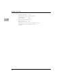
By using one of the offset registers, the disassembled code
addresses can be made to match the listing file addresses as follows:
2-7
Using the 16XBug Debugger
2
167Bug>OF R0
R0 =00000000 00000000? 1327C. <CR>
167Bug>MD 0+R0;DI <CR>
00000+R0 48E78080
MOVEM.L
00004+R0 4280
CLR.L
00006+R0 1018
MOVE.B
00008+R0 5340
SUBQ.W
0000A+R0 12D8
MOVE.B
0000C+R0 51C8FFFC
DBF
00010+R0 4CDF0101
MOVEM.L
00014+R0 4E75
RTS
167Bug>
D0/A0,—(A7)
D0
(A0)+,D0
#1,D0
(A0)+,(A1)+
D0,$A+R0
(A7)+,D0/A0
For additional information about the offset registers, refer to the OF
command description.
Port Numbers
Some 16XBug commands give you the option to choose the port to
be used to input or output. Refer to the board installation manual
for port information.
Entering and Debugging Programs
There are various ways to enter a user program into system
memory for execution. One way is to create the program using the
Memory Modify (MM) command with the assembler/
disassembler option. You enter the program one source line at a
time. After each source line is entered, it is assembled and the object
code is loaded to memory. Refer to Chapter 4 for complete details
of the 16XBug Assembler/Disassembler.
Another way to enter a program is to download an object file from
a host system. The program must be in S-record format (described
in Appendix C) and may have been assembled or compiled on the
host system. Alternately, the program may have been previously
created using the 16XBug MM command as outlined above and
stored to the host using the Dump (DU) command. A
communication link must exist between the host system and the
2-8
Calling System Utilities from User Programs
MVME16X port 1. (Hardware configuration details are in the
section on Installation and Startup in Chapter 1.) The file is
downloaded from the host to MVME16X memory by the Load (LO)
command.
Another way is by reading in the program from disk, using one of
the disk commands (BO, BH, IOP). Once the object code has been
loaded into memory, you can set breakpoints if desired and run the
code or trace through it.
Yet another way is via the network, using one of the network disk
commands (NBO, NBH, NIOP).
Calling System Utilities from User Programs
A convenient way of doing character input/output and many other
useful operations has been provided so that you do not have to
write these routines into the target code. You can access various
16XBug routines via one of the MC68040 and MC68060 TRAP
instructions, using vector #15. Refer to Chapter 5 for details on the
various TRAP #15 utilities available and how to invoke them from
within a user program.
Preserving the Debugger Operating
Environment
This section explains how to avoid contaminating the operating
environment of the debugger. 16XBug uses certain of the
MVME16X onboard resources and also offboard system memory to
contain temporary variables, exception vectors, etc. If you disturb
resources upon which 16XBug depends, then the debugger may
function unreliably or not at all.
If your application enables translation through the Memory
Management Units (MMUs), and utilizes resources of the debugger
(e.g., system calls), your application must create the necessary
2-9
2
Using the 16XBug Debugger
translation tables for the debugger to have access to its various
resources. The debugger honors the enabling of the MMUs; it does
not disable translation.
2
16XBug Vector Table and Workspace
As described in the Memory Requirements section in Chapter 1,
16XBug needs 64KB of read/write memory to operate. The 16XBug
reserves a 1024-byte area for a user program vector table area and
then allocates another 1024-byte area and builds an exception
vector table for the debugger itself to use. Next, 16XBug reserves
space for static variables and initializes these static variables to
predefined default values. After the static variables, 16XBug
allocates space for the system stack, then initializes the system stack
pointer to the top of this area.
With the exception of the first 1024-byte vector table area, you must
be extremely careful not to use the above-mentioned memory areas
for other purposes. You should refer to the Memory Requirements
section in Chapter 1 and to Appendix A to determine how to dictate
the location of the reserved memory areas. If, for example, your
program inadvertently wrote over the static variable area
containing the serial communication parameters, these parameters
would be lost, resulting in a loss of communication with the system
console terminal. If your program corrupts the system stack, then
an incorrect value may be loaded into the processor Program
Counter (PC), causing a system crash.
Hardware Functions
The only hardware resources used by the debugger are the EIA232-D ports, which are initialized to interface to the debug terminal.
If these ports are reprogrammed, the terminal characteristics must
be modified to suit, or the ports should be restored to the debuggerset characteristics prior to reinvoking the debugger.
2-10
Preserving the Debugger Operating Environment
Exception Vectors Used by 16XBug
2
The exception vectors used by the debugger are listed below. These
vectors must reside at the specified offsets in the target program's
vector table for the associated debugger facilities (breakpoints,
trace mode, etc) to operate.
Table 2-2. Exception Vectors Used by 16XBug
Vector
Offset
Exception
16XBug Facility
$10
Illegal instruction
Breakpoints (used by GO, GN,
GT)
$24
Trace
Trace operations (such as T, TC,
TT)
$80-$B8
TRAP #0 - #14
Used internally
$BC
TRAP #15
System calls (refer to Chapter 5)
$NOTE
Level 7 interrupt
ABORT pushbutton
$NOTE
Level 7 interrupt
AC Fail
$DC
FP Unimplemented
Data Type
Software emulation and data type
conversion of ßoating point data.
Note
This depends on what the Vector Base Register (VBR) is set to in
the MCchip.
For the MVME162, the ABORT pushbutton vector offset
depends on what the contents of the Vector Base Register (VBR)
is set to in the MCchip. The AC Fail vector offset depends on
what the contents of the Vector Base Register is set to in the
VMEchip2.
When the debugger handles any exception, the target stack pointer
is left pointing past the bottom of the exception stack frame created;
that is, it reflects the system stack pointer values just before the
exception occurred. In this way, the operation of the debugger
facility (through an exception) is transparent to users.
2-11
Using the 16XBug Debugger
Example
2
Trace one instruction using debugger.
167Bug>RD
PC =00010000 SR =2700=TR:OFF_S._7_.....
USP =0000DFFC MSP =0000EFFC ISP* =0000FFFC
DFC =0=F0
CACR =0=........
D0 =00000000 D1 =00000000 D2 =00000000
D4 =00000000 D5 =00000000 D6 =00000000
A0 =00000000 A1 =00000000 A2 =00000000
A4 =00000000 A5 =00000000 A6 =00000000
00010000 203C0000 0001
MOVE.L
#$1,D0
167Bug>T
PC =00010006 SR =2700=TR:OFF_S._7_.....
USP =0000DFFC MSP =0000EFFC ISP* =0000FFFC
DFC =0=F0
CACR =0=........
D0 =00000001 D1 =00000000 D2 =00000000
D4 =00000000 D5 =00000000 D6 =00000000
A0 =00000000 A1 =00000000 A2 =00000000
A4 =00000000 A5 =00000000 A6 =00000000
00010006 D280
ADD.L
D0,D1
167Bug>
VBR =00000000
SFC =0=F0
D3
D7
A3
A7
=00000000
=00000000
=00000000
=0000FFFC
VBR =00000000
SFC =0=F0
D3
D7
A3
A7
=00000000
=00000000
=00000000
=0000FFFC
Notice that the value of the target stack pointer register (A7) has not
changed even though a trace exception has taken place. Your
program may either use the exception vector table provided by
16XBug or it may create a separate exception vector table of its own.
The two following sections detail these two methods.
Using the 16XBug Target Vector Table
The 16XBug initializes and maintains a vector table area for target
programs. A target program is any program started by the bug,
either manually with GO or TR type commands or automatically
with the BO command. The start address of this target vector table
area is the base address of the debugger memory. This address is
loaded into the target-state VBR at power up and cold-start reset
and can be observed by using the RD command to display the
target-state registers immediately after power up.
2-12
Preserving the Debugger Operating Environment
The 16XBug initializes the target vector table with the debugger
vectors listed in Table 2-2 and fills the other vector locations with
the address of a generalized exception handler. The target program
may take over as many vectors as desired by simply writing its own
exception vectors into the table. If the vector locations listed in
Table 2-2 are overwritten then the accompanying debugger
functions are lost.
The 16XBug maintains a separate vector table for its own use. In
general, you do not have to be aware of the existence of the
debugger vector table. It is completely transparent and you should
never make any modifications to the vectors contained in it.
Creating a New Vector Table
Your program may create a separate vector table in memory to
contain its exception vectors. If this is done, the program must
change the value of the VBR to point at the new vector table. In
order to use the debugger facilities you can copy the proper vectors
from the 16XBug vector table into the corresponding vector
locations in your program vector table.
The vector for the 16XBug generalized exception handler may be
copied from offset $08 (bus error vector) in the target vector table to
all locations in your program vector table where a separate
exception handler is not used. This provides diagnostic support in
the event that your program is stopped by an unexpected
exception. The generalized exception handler gives a formatted
display of the target registers and identifies the type of the
exception.
The following is an example of a routine which builds a separate
vector table and then moves the VBR to point at it:
2-13
2
Using the 16XBug Debugger
2
*
*** BUILDX - Build exception vector table ****
*
BUILDX MOVEC.L VBR,A0
Get copy of VBR.
LEA
$10000,A1
New vectors at $10000.
MOVE.L
$80(A0),D0
Get generalized exception vector.
MOVE.W
$3FC,D1
Load count (all vectors).
LOOP
MOVE.L
D0,(A1,D1)
Store generalized exception vector.
SUBQ.W
#4,D1
BNE.B
LOOP
Initialize entire vector table.
MOVE.L
$10(A0),$10(A1)
Copy breakpoints vector.
MOVE.L
$24(A0),$24(A1)
Copy trace vector.
MOVE.L
$BC(A0),$BC(A1)
Copy system call vector.
LEA.L
COPROCC(PC),A2
Get your exception vector.
MOVE.L
A2,$2C(A1)
Install as F-Line handler.
MOVEC.L A1,VBR
Change VBR to new table.
RTS
END
It may turn out that your program uses one or more of the exception
vectors that are required for debugger operation. Debugger
facilities may still be used, however, if your exception handler can
determine when to handle the exception itself and when to pass the
exception to the debugger.
When an exception occurs which you want to pass on to the
debugger; i.e., ABORT, your exception handler must read the
vector offset from the format word of the exception stack frame.
This offset is added to the address of the 16XBug target program
vector table (which your program saved), yielding the address of
the 16XBug exception vector. The program then jumps to the
address stored at this vector location, which is the address of the
16XBug exception handler.
Your program must make sure that there is an exception stack
frame in the stack and that it is exactly the same as the processor
would have created for the particular exception before jumping to
the address of the exception handler.
The following is an example of an exception handler which can pass
an exception along to the debugger:
2-14
Floating Point Support
2
*
*** EXCEPT - Exception handler ****
*
EXCEPT SUBQ.L
#4,A7
Save space in stack for a PC value.
LINK
A6,#0
Frame pointer for accessing PC space.
MOVEM.L A0-A5/D0-D7,-(SP) Save registers.
:
: decide here if your code handles exception, if so, branch...
:
MOVE.L
BUFVBR,A0
Pass exception to debugger; Get saved VBR.
MOVE.W
14(A6),D0
Get the vector offset from stack frame.
AND.W
#$0FFF,D0
Mask off the format information.
MOVE.L
(A0,D0.W),4(A6)
Store address of debugger exc handler.
MOVEM.L (SP)+,A0-A5/D0-D7 Restore registers.
UNLK
A6
RTS
Put addr of exc handler into PC and go.
Floating Point Support
The floating point unit (FPU) of the MC68040 and MC68060
microprocessors is supported in 16XBug. The MD, MM, RM, and
RS commands allow display and modification of floating point
data in registers and in memory. Floating point instructions can be
assembled/disassembled with the DI option of the MD and MM
commands.
Valid data types that can be used when modifying a floating point
data register or a floating point memory location:
Integer Data Types
12
Byte
1234
Word
12345678
Longword
Floating Point Data Types
1_FF_7FFFFF
1_7FF_FFFFFFFFFFFFF
-3.12345678901234501_E+123
Single Precision Real Format
Double Precision Real Format
ScientiÞc Notation Format
(decimal)
2-15
Using the 16XBug Debugger
When entering data in single or double precision format, the
following rules must be observed:
2
1. The sign field is the first field and is a binary field.
2. The exponent field is the second field and is a hexadecimal
field.
3. The mantissa field is the last field and is a hexadecimal field.
4. The sign field, the exponent field, and at least the first digit of
the mantissa field must be present (any unspecified digits in
the mantissa field are set to zero).
5. Each field must be separated from adjacent fields by an
underscore.
6. All the digit positions in the sign and exponent fields must be
present.
Single Precision Real
This format would appear in memory as:
1-bit sign Þeld
(1 binary digit)
8-bit biased exponent Þeld (2 hex digits. Bias = $7F)
23-bit fraction Þeld
(6 hex digits)
A single precision number takes 4 bytes in memory.
Double Precision Real
This format would appear in memory as:
1-bit sign Þeld
(1 binary digit)
11-bit biased exponent Þeld (3 hex digits. Bias = $3FF)
52-bit fraction Þeld
(13 hex digits)
A double precision number takes 8 bytes in memory.
2-16
Floating Point Support
Notes 1. The single and double precision formats have an
implied integer bit (always 1).
2
2. The 68K debuggers do NOT support extended (X)
display options such as extended precision format (;X)
or packed decimal format (;P). If you attempt to use
these formats, the debugger will return an **** Illegal
Option **** error message.
Scientific Notation
This format provides a convenient way to enter and display a
floating point decimal number. Internally, the number is assembled
into a packed decimal number and then converted into a number of
the specified data type.
Entering data in this format requires the following fields:
❏
A sign bit (+ or -); if omitted, default is +.
❏
One decimal digit followed by a decimal point.
❏
Up to 17 decimal digits (at least one must be entered).
❏
An optional Exponent field that consists of:
Ð An optional underscore.
Ð The Exponent field identifier, letter "E".
Ð An optional Exponent sign (+, -).
Ð From 1 to 3 decimal digits.
For more information about the floating point unit of the MC68040
and MC68060 microprocessors, refer to the appropriate
microprocessor user's manual (see the Related Documentation
section in the Preface).
2-17
Using the 16XBug Debugger
2
2-18
3Debugger Commands
3
Introduction
This chapter contains descriptions of each debugger command,
with one or more examples of each. The 16XBug debugger
commands are summarized in Table 3-1.
Table 3-1. Debugger Commands
Command
Mnemonic
Title
AB/NOAB
Automatic Bootstrap Operating System/No Autoboot
AS
One Line Assembler
BC
Block of Memory Compare (Note 2)
BF
Block of Memory Fill (Note 2)
BH
Bootstrap Operating System and Halt
BI
Block of Memory Initialize
BM
Block of Memory Move (Note 2)
BO
Bootstrap Operating System
BR/NOBR
Breakpoint Insert/Delete
BS
Block of Memory Search (Note 2)
BV
Block of Memory Verify (Note 2)
CM/NOCM
Concurrent Mode/No Concurrent Mode
CNFG
ConÞgure Board Information Block
CS
Checksum (Note 2)
DC
Data Conversion (Note 2)
DMA
DMA Block of Memory Move
DS
One Line Disassembler
3-1
Debugger Commands
Table 3-1. Debugger Commands (Continued)
3
3-2
Command
Mnemonic
Title
DU
Dump S-Records
ECHO
Echo String
ENV
Set Environment to Bug/Operating System
GD
Go Direct (Ignore Breakpoints)
GN
Go to Next Instruction
GO
Go Execute User Program
GT
Go to Temporary Breakpoint
HE
Help (NOTE 2)
IOC
I/O Control for Disk
IOI
I/O Inquiry
IOP
I/O Physical (Direct Disk Access) (Note 2)
IOT
I/O Teach for ConÞguring Disk Controller (Note 2)
IRQM
Interrupt Request Mask
LO
Load S-Records from Host (Note 2)
MA/NOMA
Macro DeÞne/Display/Delete
MAE
Macro Edit
MAL/NOMAL
Enable/Disable Macro Expansion Listing
MAR
Load Macros
MAW
Save Macros
MD
Memory Display (Note 2)
MENU
System Menu
MM
Memory Modify (Note 2)
MMD
Memory Map Diagnostic
MS
Memory Set (Note 2)
MW
Memory Write
Introduction
Table 3-1. Debugger Commands (Continued)
Command
Mnemonic
Title
NAB
Automatic Network Boot Operating System
NBH
Network Boot Operating System and Halt
NBO
Network Boot Operating System
NIOC
Network I/O Control
NIOP
Network I/O Physical (Note 2)
NIOT
Network I/O Teach (Note 2)
NPING
Network Ping
OF
Offset Registers Display/Modify
PA/NOPA
Printer Attach/Detach
PF/NOPF
Port Format/Detach (Note 2)
PFLASH
Program FLASH Memory (Note 2)
PS
Put RTC into Power Save Mode for Storage
RB/NORB
ROMboot Enable/Disable
RD
Register Display
REMOTE
Connect Remote Modem to CSO
RESET
Cold/Warm Reset
RL
Read Loop
RM
Register Modify
RS
Register Set
SD
Switch Directories
SET
Set Time and Date (Note 2)
SYM/NOSYM
Symbol Table Attach/Detach
SYMS
Symbol Table Display/Search
T
Trace
TA
Terminal Attach
3
3-3
Debugger Commands
Table 3-1. Debugger Commands (Continued)
3
Command
Mnemonic
Title
TC
Trace on Change of Control Flow
TIME
Display Time and Date (Note 2)
TM
Transparent Mode (Note 2)
TT
Trace to Temporary Breakpoint
VE
Verify S-Records Against Memory (Note 2)
VER
Revision/Version Display
WL
Write Loop
Notes
1.
2.
In most examples of commands and displays given in this manual,
167Bug is used. However, the commands, displays, and system calls
apply to all 68K CISC debugging packages, unless otherwise noted.
These commands are also part of the reduced command set
contained in the BootBug PROM for boards that have a BootBug
function.
Each of the individual commands is described in the following
pages. The command syntax is shown using the symbols explained
in Chapter 2.
In the examples shown, the symbol <CR> represents the carriage
Return or Enter key on your terminal keyboard. Whenever this
symbol appears, it means that you should enter a carriage return.
3-4
AB/NOAB - Automatic Bootstrap Operating System/No Autoboot
AB/NOAB - Automatic Bootstrap Operating
System/No Autoboot
3
Command Input
AB [;V]
NOAB
Description
The AB command re-invokes the autoboot sequence.
The option field V (verbose) enables the autoboot sequence to
display the controller and device numbers while it is scanning as
well as the returned packet status.
The NOAB command disables the automatic boot function.
Examples
167-Bug>AB
Enables the autoboot function.
167-Bug>NOAB
Disables the autoboot function but
does not change the parameters.
3-5
Debugger Commands
AS - One Line Assembler
Command Input
3
AS address
Description
This is synonymous with the MM address;DI command. (Refer to it
for details.) It provides access to the one-line assembler described in
Chapter 4. Accordingly, it is not described further here.
3-6
BC - Block of Memory Compare
BC - Block of Memory Compare
Command Input
3
BC range address [; B|W|L]
Options
B
W
L
Byte
Word (default)
Longword
Description
The BC command compares the contents of memory defined by
range with another place in memory, beginning at address.
The option field B, W, or L (upper- or lowercase) defines the size of
data compared, and also, if range is specified using a count, defines
the size of data element to which the count refers. For example, a
count of 4 with an option of L would mean to compare 4 longwords
(16 bytes).
If the range beginning address is greater than or equal to the end
address, an error message is displayed and no comparison takes
place.
For the following examples, assume that memory blocks 2000020020 and 21000-21020 contain identical data.
Example 1: Memory compare, nothing printed.
167-Bug>BC 20000 2001F 21000
Effective address: 00020000
Effective address: 0002001F
Effective address: 00021000
167-Bug>
3-7
Debugger Commands
Example 2: Memory compare, nothing printed.
167-Bug>BC 20000:20 21000;B
Effective address: 00020000
Effective count : &32
Effective address: 00021000
167-Bug>
3
Example 3: Create a mismatch.
167-Bug>MM
0002100F 21?
167-Bug>
2100F;B
0.
167-Bug>BC 20000:20 21000;B
Effective address: 00020000
Effective count : &32
Effective address: 00021000
0002000F|21 0002100F|00
167-Bug>
3-8
Mismatches are printed out.
BF - Block of Memory Fill
BF - Block of Memory Fill
Command Input
3
BF range data [increment] [; B|W|L]
Arguments
data and increment are both expression parameters.
Options
B
W
L
Byte
Word (default)
Longword
Description
The BF command fills the specified range of memory with a data
pattern. If an increment is specified, then data is incremented by
this value following each write, otherwise data remains a constant
value. A decrementing pattern may be accomplished by entering a
negative increment. The data that you enter is right-justified in
either a byte, word, or longword field (as specified by the option
selected).
If the user-entered data does not fit into the data field size, then
leading bits are truncated to make it fit. If truncation occurs, then a
message is printed stating the data pattern which was actually
written (or initially written if an increment was specified).
If the user-entered increment does not fit into the data field size,
then leading bits are truncated to make it fit. If truncation occurs,
then a message is printed stating the increment which was actually
used.
If the upper address of the range is not on the correct boundary for
an integer multiple of the data to be stored, then data is stored to the
last boundary before the upper address. No address outside of the
3-9
Debugger Commands
specified range is ever disturbed in any case. The "Effective
address" messages displayed by the command show exactly where
data was stored.
3
Example 1
Assume memory from $20000 through $2002F is clear.
167-Bug>BF 20000,2001F 4E71 <CR>
Effective address: 00020000
Effective address: 0002001F
167-Bug>MD 20000:18;W <CR>
00020000 4E71 4E71 4E71 4E71 4E71 4E71 4E71
4E71
NqNqNqNqNqNqNqNq
00020010 4E71 4E71 4E71 4E71 4E71 4E71 4E71
4E71
NqNqNqNqNqNqNqNq
00020020 0000 0000 0000 0000 0000 0000 0000
0000
................
Because no option was specified, the length of the data field
defaulted to word.
Example 2
Assume memory from $20000 through $2002F is clear.
167-Bug>BF 20000:10 4E71 ;B <CR>
Effective address: 00020000
Effective count : &16
Data = $71
167-Bug>MD 20000:18 <CR>
00020000 7171 7171 7171 7171 7171 7171 7171
7171
qqqqqqqqqqqqqqqq
00020010 0000 0000 0000 0000 0000 0000 0000
0000
................
00020020 0000 0000 0000 0000 0000 0000 0000
0000
................
The specified data did not fit into the specified data field size. The
data was truncated and the "Data = " message was output.
3-10
BF - Block of Memory Fill
Example 3
Assume memory from $20000 through $2002F is clear.
167-Bug>BF 20000,20006 12345678 ;L <CR>
Effective address: 00020000
Effective address: 00020003
167-Bug>MD 20000:18 <CR>
00020000 1234 5678 0000 0000 0000 0000 0000
0000
.4Vx............
00020010 0000 0000 0000 0000 0000 0000 0000
0000
................
00020020 0000 0000 0000 0000 0000 0000 0000
0000
................
3
The longword pattern would not fit evenly in the given range. Only
one longword was written and the "Effective address" messages
reflect the fact that data was not written all the way up to the
specified address.
Example 4
Assume memory from $20000 through $2002F is clear.
167-Bug>BF 20000:18 0 1 ;W<CR>
Effective address: 00020000
Effective count : &48
167-Bug>MD 20000:18 <CR>
00020000 0000 0001 0002 0003 0004 0005 0006
0007
................
00020010 0008 0009 000A 000B 000C 000D 000E
000F
................
00020020 0010 0011 0012 0013 0014 0015 0016
0017
................
3-11
Debugger Commands
BH - Bootstrap Operating System and Halt
Command Input
3
BH [controllerLUN] [deviceLUN] [string]
Arguments
controllerLUN
is the Logical Unit Number (LUN) of the
controller to which the following device is
attached. Defaults to LUN 0.
deviceLUN
is the LUN of the device from which to boot.
Defaults to LUN 0.
string
is a string that is passed to the operating
system or control program loaded. Its syntax
and use is completely defined by the loaded
program.
Description
BH is used to load an operating system or control program from
disk into memory. This command works in exactly the same way
as the BO command, except that control is not given to the loaded
program. After the registers are initialized, control is returned to
the 16XBug debugger and the prompt reappears on the terminal
screen. Because control is retained by 16XBug, all the 16XBug
facilities are available for debugging the loaded program if
necessary.
A device probe with entry into the device descriptor table is done
whenever a specified device is accessed via BH.
The device probe mechanism utilizes the SCSI commands "Inquiry"
and "Mode Sense". If the specified controller is non-SCSI, the probe
simply returns a status of "device present and unknown". The
device probe makes an entry into the device descriptor table with
the pertinent data. After an entry has been made, the next time a
probe is done it simply returns with "device present" status (pointer
to the device descriptor).
3-12
BH - Bootstrap Operating System and Halt
Example 1:
167-Bug>bh
4,1 <CR>
Boot and halt from Controller LUN 4,
Device LUN 0.
Booting from: VME350, Controller 4, Drive 0
Loading: Operating System
Volume: V/68
IPL loaded at: $00010000
167-Bug>
Example 2
167-Bug>bh
4,0,test167 <CR> Boot and halt from Controller LUN
4, Device LUN 0, and pass the string
"test167" to the loaded program.
Booting from: VME350, Controller 4, Drive 0
Loading: test167
Volume: V/68
IPL loaded at: $00010000
167-Bug>
Refer to the BO command description for more detailed
information about what happens during bootstrap loading.
3-13
3
Debugger Commands
BI - Block of Memory Initialize
Command Input
3
BI range [;B|W|L]
Options
B
W
L
Byte
Word (default)
Longword
Description
The BI command may be used to initialize parity for a block of
memory. The BI command is non-destructive; if the parity is
correct for a memory location, then the contents of that memory
location are not altered.
The limits of the block of memory to be initialized may be specified
using a range. The option field specifies the data size in which
memory is initialized if range is specified using a count. The option
also specifies the size of data element to which the count refers. The
length option is valid only when a count is entered.
BI works through the memory block by reading from locations and
checking parity. If the parity is not correct, then the data read is
written back to the memory location in an attempt to correct the
parity. If the parity is not correct after the write, then the message
"RAM FAIL" is output and the address is given.
This command may take several seconds to initialize a large block
of memory.
Example 1
167-Bug>BI 0 : 10000 ;B <CR>
Effective address: 00000000
Effective count : &65536
167-Bug>
3-14
BI - Block of Memory Initialize
Example 2
Assume system memory from $0 to $000FFFFF.
167-Bug>BI 0,1FFFFF <CR>
Effective address: 00000000
Effective address: 001FFFFF
RAM FAIL AT $00100000
167-Bug>
3
3-15
Debugger Commands
BM - Block of Memory Move
Command Input
3
BM range address [; B|W|L]
Options
B
W
L
Byte
Word (default)
Longword
Description
The BM command copies the contents of the memory addresses
defined by range to another place in memory, beginning at address.
The option field is only allowed when range is specified using a
count. In this case, the B, W, or L defines the size of data that the
count is referring to. For example, a count of 4 with an option of W
would mean to move 4 words (or 8 bytes) to the new location. If an
option field is specified without a count in the range, an error results.
Example 1
Assume memory from 20000 to 2000F is clear.
167-Bug>MD
21000:10 <CR>
00021000 5448 4953 2049 5320
4120 5445 5354 2121
00021010 0000 0000 0000 0000
0000 0000 0000 0000
167-Bug>BM 21000 2100F 20000
Effective address: 00021000
Effective address: 0002100F
Effective address: 00020000
167-Bug>MD
<CR>
20000:10 <CR>
00020000 5448 4953 2049 5320
4120 5445 5354 2121
THIS IS A TEST!!
00020010 0000 0000 0000 0000
0000 0000 0000 0000
................
167-Bug>
3-16
THIS IS A TEST!!
................
BM - Block of Memory Move
Example 2
This utility is very useful for patching assembly code in memory.
Suppose you had a short program in memory at address $20000.
167-Bug>MD 20000 2000A;DI
00020000
D480
ADD.L
00020002
E2A2
ASR.L
00020004
2602
MOVE.L
00020006
4E4F0021
SYSCALL
0002000A
4E71
NOP
167-Bug>
D0,D2
D1,D2
D2,D3
.OUTSTR
Now suppose you would like to insert a NOP between the ADD.L
instruction and the ASR.L instruction. You could Block Move the
object code down two bytes to make room for the NOP.
167-Bug>BM 20002 2000B 20004
Effective address: 00020002
Effective address: 0002000B
Effective address: 00020004
167-Bug>MD 20000 2000C;DI
00020000
D480
ADD.L
00020002
E2A2
ASR.L
00020004
E2A2
ASR.L
00020006
2602
MOVE.L
00020008
4E4F0021
SYSCALL
0002000C
4E71
NOP
167-Bug>
D0,D2
D1,D2
D1,D2
D2,D3
.OUTSTR
Now you simply need to enter the NOP at address $20002.
167-Bug>MM 20002;DI
00020002
E2A2
ASR.L
00020002
4E71
NOP
00020004
E2A2
ASR.L
167-Bug>
167-Bug>MD 20000
00020000
D480
00020002
4E71
D1,D2 ?
NOP
D1,D2 ?
.
2000C;DI
ADD.L
NOP
D0,D2
3-17
3
Debugger Commands
00020004
00020006
00020008
0002000C
167-Bug>
3
3-18
E2A2
2602
4E4F0021
4E71
ASR.L
MOVE.L
SYSCALL
NOP
D1,D2
D2,D3
.OUTSTR
BO - Bootstrap Operating System
BO - Bootstrap Operating System
Command Input
3
BO [controllerLUN] [deviceLUN] [string]
Arguments
controllerLUN
is the Logical Unit Number (LUN) of the
controller to which the following device is
attached. Defaults to LUN 0.
deviceLUN
is the LUN of the device from which to boot.
Defaults to LUN 0.
string
is a string that is passed to the operating
system or control program loaded. Its syntax
and use is completely defined by the loaded
program.
Description
BO is used to load an operating system or control program from
disk into memory and give control to it. Where to find the program
and where in memory to load it is contained in block 0 of the Device
LUN specified. (Refer to Appendix D.) The device configuration
information is located in block 1 (Appendix D). The device and
controller configurations used when BO is initiated can be
examined and changed via the I/O Teach (IOT) command.
Upon the retrieval of the device configuration information (located
in block #1 of the device), the boot process will examine the ENV
flag parameter "Ignore CFGA Block on a Hard Disk Boot".
Depending on the state of the flag, the boot process will either
reconfigure the device or not. If the flag is set to "Y", the
reconfiguration process will not be done .
In older devices (e.g., ESDI, ST506, Winchester), the reconfiguration
of the hard disk drive was necessary. With all the Motorola-tested
SCSI hard disk drives, this reconfiguration is not necessary.
3-19
Debugger Commands
A device probe with entry into the device descriptor table is done
whenever a specified device is accessed via BO.
The device probe mechanism utilizes the SCSI commands "Inquiry"
and "Mode Sense". If the specified controller is non-SCSI, the probe
simply returns a status of "device present and unknown". The
device probe makes an entry into the device descriptor table with
the pertinent data.
3
After an entry has been made, the next time a probe is done it
simply returns with "device present" status (pointer to the device
descriptor).
The following sequence of events occurs when BO is invoked:
1. Block 0 of the Controller LUN and Device LUN specified is
read into memory.
2. Locations $F8 (248) through $FF (255) of block 0 are checked
to contain the string "MOTOROLA". If it is not found, the
boot sequence aborts and displays an error message: Bad
VID Block.
3. The following information is extracted from block 0:
$90 (144) - $93 (147): Configuration area starting block.
$94 (148)
: Configuration area length in blocks.
If any of the above two fields is zero, the present controller
configuration is retained; otherwise the first block of the
configuration area is read and the controller reconfigured.
4. The program is read from disk into memory. The following
locations from block 0 contain the necessary information to
initiate this transfer:
$14 (20) - $17 (23) : Block number of first sector to load from
disk.
$18 (24) - $19 (25) : Number of blocks to load from disk.
$1E (30) - $21 (33) : Starting memory location to load.
5. The first eight locations of the loaded program must contain
a "pseudo reset vector", which is loaded into the target
registers:
3-20
BO - Bootstrap Operating System
0-3: Initial value for target system stack pointer.
4-7: Initial value for target PC. If less than load address+8,
then it represents a displacement that, when added to the
starting load address, yields the initial value for the target PC.
6. Other target registers are initialized with certain arguments.
The resultant target state is shown below:
PC = Entry point of loaded program (loaded from "pseudo
reset vector").
SR = $2700.
D0 = Device LUN.
D1 = Controller LUN.
D4 = 'IPLx', with x = $0C ($49504C0C)
The ASCII string 'IPL' indicates that this is the Initial
Program Load sequence; the code $0C indicates TRAP #15
support with stack parameter passing and TRAP #15 disk
support.
A0 = Address of Disk Controller.
A1 = Entry point of loaded program.
A2 = Address of Media Configuration Block. Zero if no
configuration loaded.
A5 = Start of string (after command parameters).
A6 = End of string + 1 (if no string was entered A5=A6).
A7 = Initial stack pointer (loaded from "pseudo reset vector").
7. Control is given to the loaded program. Note that the
arguments passed to the target program, as for example, the
string pointers, may be used or ignored by the target
program.
Examples
167-Bug>BO
<CR>
Boot from Controller LUN 0, Device
LUN 0.
167-Bug>BO
3 <CR
Boot from Controller LUN 3, Device
LUN 0.
167-Bug>BO
, 3 <CR>
Boot from Controller LUN 0, Device
LUN 3.
3-21
3
Debugger Commands
167-Bug>BO
3
3-22
8 0,test <CR>
Boot from Controller LUN 8, Device
LUN 0, and pass the string "test" to
the booted program.
BR - Breakpoint Insert/Delete
BR - Breakpoint Insert/Delete
Command Input
3
BR [address[:count]]
NOBR [address]
Description
The BR command allows you to set a target code instruction
address as a "breakpoint address" for debugging purposes. If,
during target code execution, a breakpoint with 0 count is found,
the target code state is saved in the target registers and control is
returned back to 16XBug. This allows you to see the actual state of
the processor at selected instructions in the code.
Up to eight breakpoints can be defined. The breakpoints are kept
in a table which is displayed each time either BR or NOBR is used.
If an address is specified with the BR command, that address is
added to the breakpoint table. The count field specifies how many
times the instruction at the breakpoint address must be fetched
before a breakpoint is taken. The count, if greater than zero, is
decremented with each fetch. Every time that a breakpoint with
zero count is found, a breakpoint handler routine prints the CPU
state on the screen and control is returned to 16XBug.
NOBR is used for deleting breakpoints from the breakpoint table.
If an address is specified, then that address is removed from the
breakpoint table. If NOBR <CR> is entered, then all entries are
deleted from the breakpoint table and the empty table is displayed.
Example
167-Bug>BR
14000,14200 14700:&12 <CR>Set some breakpoints.
BREAKPOINTS
00014000
00014700:C
00014200
167-Bug>NOBR
14200 <CR>
BREAKPOINTS
00014000
00014700:C
Delete one breakpoint.
3-23
Debugger Commands
167-Bug>NOBR
BREAKPOINTS
167-Bug>
3
3-24
<CR>
Delete all breakpoints.
BS - Block of Memory Search
BS - Block of Memory Search
Command Input
3
BS range text [;B|W|L]
or
BS range data [mask] [;B|W|L [,N][,V]]
Arguments
text
An ASCII text string that is matched against a range of
memory.
data
A data pattern that is matched against a range of memory.
mask
A string that indicates which bit positions in data to
compare to memory (a 1 is compared, a 0 is not). The default
is all 1s.
Options
B
W
L
N
V
Byte
Word
Longword
Non-aligned
Verify
Description
The block search command searches the specified range of memory
for a match with a user-entered data pattern. This command has
three modes, as described below.
Mode 1 - LITERAL STRING SEARCH -- In this mode, a search is
carried out for the ASCII equivalent of the literal string you entered.
This mode is assumed if the single quote (') indicating the
beginning of a text field is encountered following range. The size as
specified in the option field tells whether the count field of range
3-25
Debugger Commands
refers to bytes, words, or longwords. If range is not specified using
a count, then no options are allowed. If a match is found, then the
address of the first byte of the match is output.
3
Mode 2 - DATA SEARCH -- In this mode, you enter a data pattern
as part of the command line, and you either enter a size in the
option field or it is assumed (the assumption is word). The size
entered in the option field also dictates whether the count field in
range refers to bytes, words, or longwords. The following actions
occur during a data search:
1. The user-entered data pattern is right-justified and leading
bits are truncated or leading zeros are added as necessary to
make the data pattern the specified size.
2. A compare is made with successive bytes, words, or
longwords (depending on the size in effect) within the range
for a match with the user-entered data. Comparison is made
only on those bits at bit positions corresponding to a "1" in the
mask. If no mask is specified, then a default mask of all ones
is used (all bits are compared). The size of the mask is taken
to be the same size as the data. The default data size is word.
3. If the "N" (non-aligned) option has been selected, then the
data is searched for on a byte-by-byte basis, rather than by
words or longwords, regardless of the size of data. This is
useful if a word (or longword) pattern is being searched for,
but is not expected to lie on a word (or longword) boundary.
4. If a match is found, then the address of the first byte of the
match is output along with the memory contents. If a mask
was in use, then the actual data at the memory location is
displayed, rather than the data with the mask applied.
Mode 3 - DATA VERIFICATION -- If the "V" (verify) option has
been selected, then displaying of addresses and data is done only
when the memory contents do NOT match the user-specified
pattern. Otherwise this mode is identical to Mode 2.
3-26
BS - Block of Memory Search
For all three modes, information on matches is output to the screen
in a four-column format. If more than 24 lines of matches are found,
then output is inhibited to prevent the first match from rolling off
the screen. A message is printed at the bottom of the screen
indicating that there is more to display. To resume output, you
should simply press any character key. To cancel the output and
exit the command, you should press the BREAK key.
If a match is found (or, in the case of Mode 3, a mismatch) with a
series of bytes of memory whose beginning is within the range but
whose end is outside of the range, then that match is output and a
message is output stating that the last match does not lie entirely
within the range. You may search non-contiguous memory with
this command without causing a Bus Error.
Examples
Assume the following data is in memory.
00030000 0000 0045 7272 6F72
00030010 3446 2F2F 436F 6E66
00030020 7461 7274 3A00 0000
2053 7461 7475 733D
6967 5461 626C 6553
0000 0000 0000 0000
...Error Status=
4F//ConfigTableS
tart:...........
Mode 1: the string is not found, so a message is output.
167-Bug>BS 30000 3002F 'Task
Effective address: 00030000
Effective address: 0003002F
-not found-
Status' <CR>
Mode 1: the string is found, and the address of its first byte is
output.
167-Bug>BS 30000 3002F 'Error
Effective address: 00030000
Effective address: 0003002F
00030003
Status' <CR>
Mode 1: the string is found, but it ends outside of the range, so the
address of its first byte and a message are output.
3-27
3
Debugger Commands
167-Bug>BS 30000 3001F 'ConfigTableStart' <CR>
Effective address: 00030000
Effective address: 0003001F
00030014
-last match extends over range boundary-
3
Mode 1, using range with count and size option: count is displayed in
decimal, and the address of each occurrence of the string is output.
167-Bug>BS 30000:30 't' ; B <CR>
Effective address: 00030000
Effective count: &48
0003000A
0003000C
00030020
00030023
Mode 2, using range with count: count is displayed in decimal bytes,
and the data pattern is found & displayed.
167-Bug>BS 30000:18,2F2F <CR>
Effective address: 00030000
Effective count : &48
00030012|2F2F
Mode 2: The default size is word and the data pattern is not found,
so a message is output.
167-Bug>bs 30000,3002F 3d34
Effective address: 00030000
Effective address: 0003002F
-not found-
<CR>
Mode 2: Default size is word and non-aligned option is used, so the
data pattern is found and displayed.
167-Bug>bs 30000,3002F 3d34
Effective address: 00030000
Effective address: 0003002F
0003000F|3D34
;n <CR>
Mode 2, using range with count, mask option, and size option: count
is displayed in decimal, and the actual unmasked data patterns
found are displayed.
3-28
BS - Block of Memory Search
167-Bug>BS 30000:30 60,F0 ;B <CR>
Effective address: 00030000
Effective count : &48
00030006|6F
0003000B|61
00030015|6F
00030017|66
00030018|69
00030019|67
0003001C|62
0003001D|6C
0003001E|65
00030016|6E
0003001B|61
00030021|61
3
Mode 3, on a different block of memory, mask option, scan for
words with low nibble non-0: two locations failed to verify.
167-Bug>BS 3000 1FFFF 0000 000F;V
Effective address: 00003000
Effective address: 0001FFFF
0000C000|E501
0001E224|A30E
<CR>
3-29
Debugger Commands
BV - Block of Memory Verify
Command Input
3
BV range data [increment] [;B|W|L]
Arguments
data and increment are both expression parameters
Options
B
W
L
Byte
Word (default)
Longword
Description
The BV command compares the specified range of memory against
a data pattern. If an increment is specified, then data is incremented
by this value following each comparison, otherwise data remains a
constant value. You may accomplish a decrementing pattern by
entering a negative increment. The data you enter is right-justified
in either a byte, word, or longword field (as specified by the option
selected).
If the user-entered data or increment (if specified) does not fit into
the data field size, then leading bits are truncated to make them fit.
If truncation occurs, then a message is printed stating the data
pattern and, if applicable, the increment value actually used.
If the range is specified using a count, then the count is assumed to
be in terms of the data size.
If the upper address of the range is not on the correct boundary for
an integer multiple of the data to be stored, then data is stored to the
last boundary before the upper address. No address outside of the
specified range is read from in any case. The "Effective address"
messages displayed by the command show exactly the extent of the
area read from.
3-30
BV - Block of Memory Verify
Example 1
Assume memory from $20000 to $2002F is as indicated.
167-Bug>MD
20000:18 <CR>
00020000 4E71 4E71 4E71 4E71
00020010 4E71 4E71 4E71 4E71
00020020 4E71 4E71 4E71 4E71
3
4E71 4E71 4E71 4E71
4E71 4E71 4E71 4E71
4E71 4E71 4E71 4E71
NqNqNqNqNqNqNqNq
NqNqNqNqNqNqNqNq
NqNqNqNqNqNqNqNq
167-Bug>BV 20000 2001F 4E71 <CR>
Default size is word.
Effective address: 00020000
Effective address: 0002001F
167-Bug
Verify successful, nothing printed.
Example 2
Assume memory from $20000 to $2002F is as indicated.
167-Bug>MD
20000:18 <CR>
00020000 0000 0000 0000 0000
00020010 0000 0000 0000 0000
00020020 0000 0000 0000 0000
167-Bug>BV
0000 0000 0000 0000
0000 0000 0000 0000
0000 4AFB 4AFB 4AFB
................
................
..........J{J{J{
20000:30 0;B <CR>
Effective address: 00020000
Effective count : &48
Mismatches are printed out.
0002002A|4A 0002002B|FB 0002002C|4A 0002002D|FB 0002002E|4A 0002002F|FB
167-Bug>
Example 3
Assume memory from $20000 to $2002F is as indicated.
167-Bug>MD
20000:18 <CR>
00020000 0000 0001 0002 0003
00020010 0008 FFFF 000A 000B
00020020 0010 0011 0012 0013
167-Bug>BV
0004 0005 0006 0007
000C 000D 000E 000F
0014 0015 0016 0017
20000:18 0 1 <CR>
................
................
................
Default size is word.
3-31
Debugger Commands
Effective address: 00020000
Effective count : &48
00020012|FFFF
167-Bug
3
3-32
word)
Mismatches are printed out.
CM - Concurrent Mode
CM - Concurrent Mode
Command Input
3
CM [[port] [id-string] [baud] [phone-number]]|[;A]|[;H]
Arguments
port
Everyting output to the system console is also
echoed to this port.
id-string
The device (i.e. modem) with which
communications is established before the
concurrent mode session is activated. If no identifier
string is specified, CM will use an identifier string of
"DUMB" by default.
The identifier string must be one that is supported,
by using the choices displayed. If the identifier
string is not found in the supported list, CM
displays an error message.
baud
The baud rate specified must be one of those
supported by the bug. (Refer to the PF command.)
The baud rate also must be supported by the device
specified (identifier string). If no rate is specified,
CM uses the default baud rate associated with the
device. This is also displayed along with the
supported devices. If the baud rate is not supported,
CM displays an error message.
phone number This field is a string of any alphanumeric characters.
This string is passed directly to the device driver if
needed. In the case of modems, this string is added
to the dial recognition string. If the phone number
field is not specified, a dial-in condition is assumed
(wait for call).
When specifying arguments, if there is any previous argument field
which is not specified, it must be separated using delimiters.
3-33
Debugger Commands
Options
3
A
Lists all supported devices.
H
Displays whether concurrent mode is active or not, and if it
is, what secondary port number is being used by it.
Description
This command activates a mode in which everything that appears
on the system console terminal is also echoed to the specified port
as specified by the command line argument (port field). The
specified port is also checked for inbound characters as well. These
are also echoed to the system console terminal. If no port is
specified, CM uses port 1 by default.
If the port number specified is not currently assigned, CM displays
an error message.
The port in which concurrency is to take place must already be
configured. The baud rate need not be specified because the port is
reconfigured prior to activation. The preconfiguration of the port is
done by using the PF (Port Format) command.
Examples
To list all supported devices (id-string field) by the bug, do the
following:
167-Bug>cm;a
Concurrent Devices Supported
Device Name (ID-STRING)
DUMB
UDS2662
UDS2980
UDS3382
167-Bug>cm
Concurrent Mode Active
3-34
Default Baud
9600
1200
1200
1200
CM - Concurrent Mode
(port
(id-string
(baud
(phone-number
= 1, default)
= DUMB, default)
= 9600, default for "DUMB")
= null)
3
167-Bug>cm,,uds2662,,16024383020
Concurrent Mode Active
(port
(id-string
(baud
(phone-number
= 1, default because of null
argument)
= uds2662 modem)
= 1200, default for "uds2662")
= 16024383020)
167-Bug>cm,,uds2662,,16024383020
Concurrent Mode Active
167-Bug>cm,,uds2662,,16024383020
Concurrent Mode Already Active
167-Bug>
(Error, concurrent mode already active)
167-Bug>cm
2 uds2980 1200 18007777777
(port
(id-string
(baud
(phone-number
= 2)
= uds2980 modem)
= 1200)
= 18007777777)
167-Bug>cm 2,,dumb
Concurrent Mode Setup Failure
167-Bug>
(Error in establishing communications with port/device)
For any reason you may abort the concurrent mode setup by
pressing the BREAK key. This may be necessary if the modem is
not responding to commands from the bug.
3-35
Debugger Commands
NOCM - No Concurrent Mode
Command Input
3
NOCM
Description
This command terminates concurrent mode which was activated
by the Concurrent Mode (CM) command. Depending on the device
and the port specified with the CM command, the communication
link is appropriately closed.
Examples
167-Bug>nocm
Concurrent Mode Terminated
167-Bug>
167-Bug>nocm
Concurrent Mode Not Active
167-Bug>
(Error, concurrent mode was not active)
167-Bug>nocm
Concurrent Mode Terminated With Failure
167-Bug>
(Error, closing communications link)
3-36
CNFG - Configure Board Information Block
CNFG - Configure Board Information Block
Command Input
3
CNFG [;[I][M]]
Options
I
Initialize the unused area of the board information block
to 0.
M
Modify the board information block.
Description
This command is used to display and configure the board
information block. This block is resident within the Non-Volatile
RAM (NVRAM). The board information block contains various
elements detailing specific operation pa- rameters of the hardware.
The CNFG command does not describe the elements and their use.
The board information block contents are checksummed for
validation purposes. This checksum is the last element of the block.
Refer to the board-specific MVME16X hardware manual for the
actual location of the board information block. The MVME16X
hardware manual may also describe the elements within the board
information block, and list the size and logical offset of each
element. Refer to the board-specific MVME16X debugger manual
for the actual data structure for the CNFG command.
Example
Display the current contents of the board information block:
167-Bug>cnfg
Board (PWA) Serial Number
Board Identifier
Artwork (PWA) Identifier
MPU Clock Speed
=
=
=
=
"000000061050"
"MVME167-03
"01-W3826B03A
"2500"
"
"
3-37
Debugger Commands
Ethernet Address
Local SCSI Identifier
167-Bug>
3
= 08003E20A867
= "07"
Note that the parameters that are quoted are left-justified character
(ASCII) strings padded with space characters, and the quotes (") are
displayed to indicate the size of the string. Parameters that are not
quoted are considered data strings, and data strings are rightjustified. The data strings are padded with zeroes if the length is
not met.
In the event of corruption of the board information block, the
command displays a question mark "?" for nondisplayable
characters. A warning message is also displayed in the event of a
checksum failure.
Example
167-Bug>cnfg
WARNING: Board Information Block Checksum Error
Board (PWA) Serial Number = "????????????"
Board Identifier
= "????????????????"
Artwork (PWA) Identifier = "????????????????"
MPU Clock Speed
= "????"
Ethernet Address
= 000000000000
Local SCSI Identifier
= "??"
167-Bug>
Modification is permitted by using the M option of the command.
Example
167-Bug>cnfg;m
WARNING: Board Information Block Checksum Error
Board (PWA) Serial Number = "????????????"? 000000061050
Board Identifier
= "????????????????"? MVME167-03
Artwork (PWA) Identifier = "????????????????"? 01-W3826B03A
MPU Clock Speed
= "????"? 2500
Ethernet Address
= 000000000000? 08003E20A867
Local SCSI Identifier
= "??"? 07
3-38
CNFG - Configure Board Information Block
Update Non-Volatile RAM (Y/N)? y
167-Bug>
At the end of the modification session, you are prompted for the
update to Non-Volatile RAM (NVRAM). A Y response must be
made for the update to occur; any other response terminates the
update (disregards all changes). The update also recalculates the
checksum.
!
Caution
Be cautious when modifying parameters. Some of these
parameters are set up by the factory, and correct board
operation relies upon these parameters.
Once modification/update is complete, you can now display the
current contents as described earlier.
Example
167-Bug>cnfg
Board (PWA) Serial Number
Board Identifier
Artwork (PWA) Identifier
MPU Clock Speed
Ethernet Address
Local SCSI Identifier
167-Bug>
=
=
=
=
=
=
"000000061050"
"MVME167-03
"01-W3826B03A
"2500"
08003E20A867
"07"
"
"
3-39
3
Debugger Commands
CS - Checksum
Command Input
3
CS range [;B|W|L]
Options
Byte
Word (default)
Longword
B
W
L
The option field serves both as a data size identifier and scale factor
if a count is specified as part of the range.
Description
The Checksum command provides access to the same checksum
routine used by the powerup self-test firmware. This routine is
used in two ways within the firmware monitor.
1. At powerup, the power-up confidence test is executed. One
of the items verified is the checksum contained in the
firmware monitor EPROM. If for any reason the contents of
the EPROM were to change from the factory version, the
checksum test is designed to detect the change and inform
you of the failure.
2. Following a valid power-up test, 16XBug examines the ROM
map space for code that needs to be executed. This feature
(ROMboot) makes use of the checksum routine to verify that
a routine in memory is really there to be executed at
powerup. For more information, refer to the ROMboot section
in Chapter 1, which describes the format of the routine to be
executed and the interface provided upon entry.
This command is provided as an aid in preparing routines for the
ROMboot feature. Because ROMboot does checksum validation as
part of its screening process, you need access to the same routine in
the preparation of EPROM/ROM routines.
3-40
CS - Checksum
The addresses used in the range parameters can be provided in two
forms:
❏
An absolute address (32-bit maximum).
❏
An expression using a displacement + relative offset register.
The CS command is used to calculate/verify the contents of a block
of memory.
The algorithm used to calculate the checksum is as follows:
1. The checksum variable is set to zero.
2. Each data element is added to the checksum; if a carry is
generated, a one is added to the checksum variable.
3. This process is repeated for each data element until the
ending address is reached.
Examples
167-Bug>cs 1000 2000 <CR>
Effective address: 00001000
Effective address: 00001FFF
Checksum: 3E87
Default size is word.
167-Bug>cs 1000 2000;l <CR>
Effective address: 00001000
Effective address: 00001FFF
Checksum: A79B3E15
Size is set to longword.
167-Bug>cs FF800000:400;b <CR>
Effective address: FF800000
Effective count: &1024
Checksum: A8
Size is set to byte.
count is in hexadecimal.
167-Bug>cs FF800000:400 <CR>
Effective address: FF800000
Effective count: &2048
Checksum: CE57
Default size is word,
count is in hexadecimal.
3-41
3
Debugger Commands
DC - Data Conversion
Command Input
3
DC exp | addess [;[B][O][A]]
Options
B
Displays the output in binary.
O
Displays the output in octal.
A
Displays the ASCII character equal to the value. (If the
value is greater than $7F, the A option displays "NA".)
Description
The DC command is used to simplify an expression into a single
numeric value. This equivalent value is displayed in its
hexadecimal and decimal representation. If the numeric value
could be interpreted as a signed negative number (i.e., if the most
significant bit of the 32-bit internal representation of the number is
set), then both the signed and unsigned interpretations are
displayed.
Examples
167-Bug>DC 10 <CR>
00000010 = $10 = &16
167-Bug>DC &10-&20 <CR>
SIGNED : FFFFFFF6 = -$A = -&10
UNSIGNED: FFFFFFF6 = $FFFFFFF6 = &4294967286
167-Bug>DC 123+&345+@67+%1100001
00000314 = $314 = &788
167-Bug>DC (2*3*8) /4 <CR>
0000000C = $C = &12
167-Bug>DC 55&F <CR>
00000005 = $5 = &5
3-42
<CR>
DC - Data Conversion
167-Bug>DC 55>>1 <CR>
0000002A = $2A = &42
167-Bug>dc 1+2;b
DATA BIR: 33222222222211111111110000000000
NUMBER>>: 10987654321098765432109876543210
BINARY : 00000000000000000000000000000011
167-Bug>dc 1+2;bo
DATA BIR: 33222222222211111111110000000000
NUMBER>>: 10987654321098765432109876543210
BINARY : 00000000000000000000000000000011
OCTAL
: 00000000003
3
167-Bug>dc 1+2;boa
DATA BIR: 33222222222211111111110000000000
NUMBER>>: 10987654321098765432109876543210
BINARY : 00000000000000000000000000000011
OCTAL
: 00000000003
ASCII
: ETX
The subsequent examples assume A0=00030000 and the following
data resides in memory:
00030000 1111 1111 2222 2222 3333 3333 4444 4444
....""""3333DDDD
167-Bug>DC (A0) <CR>
00030000 = $30000 = &196608
167-Bug>
167-Bug>DC ([,A0]) <CR>
11111111 = $11111111 = &286331153
167-Bug>
167-Bug>DC (4,A0) <CR>
00030004 = $30004 = &196612
167-Bug>
167-Bug>DC ([4,A0]) <CR>
22222222 = $22222222 = &572662306
167-Bug>
3-43
Debugger Commands
DMA - DMA Block of Memory Move
Command Input
3
DMA range address vdir am block [;B|W|L] .
Description
This command utilizes the hardware capability of Direct Memory
Access (DMA). This command is used to move blocks of data from
the local bus to the VMEbus, or from the VMEbus to the local bus.
Refer to the board-specific MVME16X hardware manual for a
detailed description of this hardware feature. You can not DMA
from the local bus to the local bus, or from the VMEbus to the
VMEbus.
The DMA command copies (DMAs) the contents of the memory
addresses defined by range to another place in memory, beginning
at address.
Arguments
3-44
vdir
Specifies the direction of the transfer. When vdir equals
zero, the transfer occurs from the local bus to the
VMEbus; when vdir equals one, the transfer occurs from
the VMEbus to the local bus.
am
Specifies the VMEbus address modifier of the transfer.
Refer to the VMEbus specification (listed in Chapter 1)
for the complete list of address modifiers. The VMEbus
transfer address must also support transfers with the
selected address modifier. Refer to the applicable
hardware manuals for the target boards.
block
Specifies the block transfer mode of the transfer. This
argument can have the values of zero to three, described
as follows:
DMA - DMA Block of Memory Move
Value
0
1
2
3
Description
Block transfers disabled.
The DMA controller executes D32 block transfer cycles
on the VMEbus. In the block transfer mode, the DMA
controller may execute byte and two-byte cycles at the
beginning and ending of a transfer in non-block transfer
mode.
Block transfers disabled.
The DMA controller executes D64 block transfer cycles
on the VMEbus. In the block transfer mode, the DMA
controller may execute byte, two-byte, and four-byte
cycles at the beginning and ending of a transfer in nonblock transfer mode.
Refer to the VMEbus specification for the complete description of
block transfer mode. The VMEbus transfer address must also
support block transfers if enabled, refer to the applicable hardware
manuals.
Options
B
W
L
Byte
Word (default)
Longword
The option field is only allowed when range is specified using a
count. In this case, the B, W, or L defines the size of the data that the
count is referring to. For example, a count of four with an option of
L means to move four longwords (or 16 bytes) to the new location.
If an option field is specified without a count in the range, an error
results.
Example 1
The following local memory block has the contents of:
167-Bug>md
10000:40;l
3-45
3
Debugger Commands
00010000
00010010
00010020
00010030
00010040
00010050
00010060
00010070
00010080
00010090
000100A0
000100B0
000100C0
000100D0
000100E0
000100F0
167-Bug>
3
00000001
00080009
00100011
00180019
00200021
00280029
00300031
00380039
00400041
00480049
00500051
00580059
00600061
00680069
00700071
00780079
00020003
000A000B
00120013
001A001B
00220023
002A002B
00320033
003A003B
00420043
004A004B
00520053
005A005B
00620063
006A006B
00720073
007A007B
00040005
000C000D
00140015
001C001D
00240025
002C002D
00340035
003C003D
00440045
004C004D
00540055
005C005D
00640065
006C006D
00740075
007C007D
167-Bug>dma 10000:40 3000000 0
Effective address: 00010000
Effective count : &256
Effective address: 03000000
DMA Completion Status =00000001
167-Bug>
00060007
000E000F
00160017
001E001F
00260027
002E002F
00360037
003E003F
00460047
004E004F
00560057
005E005F
00660067
006E006F
00760077
007E007F
................
................
................
................
. .!.".#.$.%.&.'
.(.).*.+.,.-.../
.0.1.2.3.4.5.6.7
.8.9.:.;.<.=.>.?
[email protected]
.H.I.J.K.L.M.N.O
.P.Q.R.S.T.U.V.W
.X.Y.Z.[..].^._
.`.a.b.c.d.e.f.g
.h.i.j.k.l.m.n.o
.p.q.r.s.t.u.v.w
.x.y.z.{.|.}.~..
d 0;l
In this example, the DMA command was requested to move (DMA)
256 bytes of data from local address $10000 to the VMEbus address
$3000000, the address modifier was $D (Extended Supervisory
Data Access), and the block transfer was disabled.
At the end of the transfer, the DMA command displays the
completion status of the transfer. A completion status of $1 is a
successful transfer. Any other completion status means that the
transfer was not successful. This status comes directly from the
hardware status from the DMA controller.
The destination memory (VMEbus) now looks like this:
167-Bug>md
3-46
3000000:40;l
DMA - DMA Block of Memory Move
03000000
03000010
03000020
03000030
03000040
03000050
03000060
03000070
03000080
03000090
030000A0
030000B0
030000C0
030000D0
030000E0
030000F0
167-Bug>
00000001
00080009
00100011
00180019
00200021
00280029
00300031
00380039
00400041
00480049
00500051
00580059
00600061
00680069
00700071
00780079
00020003
000A000B
00120013
001A001B
00220023
002A002B
00320033
003A003B
00420043
004A004B
00520053
005A005B
00620063
006A006B
00720073
007A007B
00040005
000C000D
00140015
001C001D
00240025
002C002D
00340035
003C003D
00440045
004C004D
00540055
005C005D
00640065
006C006D
00740075
007C007D
00060007
000E000F
00160017
001E001F
00260027
002E002F
00360037
003E003F
00460047
004E004F
00560057
005E005F
00660067
006E006F
00760077
007E007F
................
................
................
................
. .!.".#.$.%.&.'
.(.).*.+.,.-.../
.0.1.2.3.4.5.6.7
.8.9.:.;.<.=.>.?
[email protected]
.H.I.J.K.L.M.N.O
.P.Q.R.S.T.U.V.W
.X.Y.Z.[..].^._
.`.a.b.c.d.e.f.g
.h.i.j.k.l.m.n.o
.p.q.r.s.t.u.v.w
.x.y.z.{.|.}.~..
3
Example 2
The following VMEbus memory block has the contents of:
167-Bug>md
3000000:40;l
03000000
FFFFFFFE FFFDFFFC FFFBFFFA FFF9FFF8
................
03000010
FFF7FFF6 FFF5FFF4 FFF3FFF2 FFF1FFF0
................
03000020
FFEFFFEE FFEDFFEC FFEBFFEA FFE9FFE8
................
03000030
FFE7FFE6 FFE5FFE4 FFE3FFE2 FFE1FFE0
................
03000040
FFDFFFDE FFDDFFDC FFDBFFDA FFD9FFD8
................
03000050
FFD7FFD6 FFD5FFD4 FFD3FFD2 FFD1FFD0
................
03000060
FFCFFFCE FFCDFFCC FFCBFFCA FFC9FFC8
................
03000070
FFC7FFC6 FFC5FFC4 FFC3FFC2 FFC1FFC0
................
03000080
FFBFFFBE FFBDFFBC FFBBFFBA FFB9FFB8
................
03000090
FFB7FFB6 FFB5FFB4 FFB3FFB2 FFB1FFB0
................
030000A0
FFAFFFAE FFADFFAC FFABFFAA FFA9FFA8
................
030000B0
FFA7FFA6 FFA5FFA4 FFA3FFA2 FFA1FFA0
................
030000C0
FF9FFF9E FF9DFF9C FF9BFF9A FF99FF98
................
030000D0
FF97FF96 FF95FF94 FF93FF92 FF91FF90
................
030000E0
FF8FFF8E FF8DFF8C FF8BFF8A FF89FF88
................
030000F0
FF87FF86 FF85FF84 FF83FF82 FF81FF80
................
167-Bug>
3-47
Debugger Commands
167-Bug>dma 3000000 3000100 10000
Effective address: 03000000
Effective address: 030000FF
Effective address: 00010000
DMA Completion Status =00000001
167-Bug>
3
1e0
In this example, the DMA command was requested to move (DMA)
256 bytes of data from VMEbus address $3000000 to the local
address $10000, the address modifier was $E (Extended
Supervisory Program Access), and the block transfer was disabled.
The destination memory (local) now looks like this:
167-Bug>md
00010000
00010010
00010020
00010030
00010040
00010050
00010060
00010070
00010080
00010090
000100A0
000100B0
000100C0
000100D0
000100E0
000100F0
167-Bug>
10000:40;l
FFFFFFFE
FFF7FFF6
FFEFFFEE
FFE7FFE6
FFDFFFDE
FFD7FFD6
FFCFFFCE
FFC7FFC6
FFBFFFBE
FFB7FFB6
FFAFFFAE
FFA7FFA6
FF9FFF9E
FF97FF96
FF8FFF8E
FF87FF86
FFFDFFFC
FFF5FFF4
FFEDFFEC
FFE5FFE4
FFDDFFDC
FFD5FFD4
FFCDFFCC
FFC5FFC4
FFBDFFBC
FFB5FFB4
FFADFFAC
FFA5FFA4
FF9DFF9C
FF95FF94
FF8DFF8C
FF85FF84
FFFBFFFA
FFF3FFF2
FFEBFFEA
FFE3FFE2
FFDBFFDA
FFD3FFD2
FFCBFFCA
FFC3FFC2
FFBBFFBA
FFB3FFB2
FFABFFAA
FFA3FFA2
FF9BFF9A
FF93FF92
FF8BFF8A
FF83FF82
FFF9FFF8
FFF1FFF0
FFE9FFE8
FFE1FFE0
FFD9FFD8
FFD1FFD0
FFC9FFC8
FFC1FFC0
FFB9FFB8
FFB1FFB0
FFA9FFA8
FFA1FFA0
FF99FF98
FF91FF90
FF89FF88
FF81FF80
................
................
................
................
................
................
................
................
................
................
................
................
................
................
................
................
Example 3
In the following example, an attempt was made to DMA to nonexistent VMEbus memory. The command displays the DMA
controller status register and the DMA controller counter registers.
Refer to the MVME166/MVME167/MVME187 Single Board
Computers Programmer's Reference Guide for the description of these
registers.
3-48
DMA - DMA Block of Memory Move
167-Bug>dma 0:1000 4000000 0 d 0;b
Effective address: 00000000
Effective count : &4096
Effective address: 04000000
DMA Completion Status =00000002
DMA Byte Counter
=00000FC0
DMA Local Bus Address Counter =00000040
DMA VMEbus Address Counter
=04000004
167-Bug>
3
3-49
Debugger Commands
DS - One Line Disassembler
Command Input
3
DS address [:count | address]
Description
This is synonymous with the MD address;DI command (refer to it),
and provides access to the disassembler. Accordingly, it is not
described further here.
3-50
DU - Dump S-Records
DU - Dump S-Records
Command Input
3
DU [port] range [text] [address] [offset] [;B|W|L]
Description
The DU command outputs data from memory in the form of
Motorola S-records to a port you specify. If you do not specify port,
the S-records are sent to the host port, and the missing port number
must be delimited by two commas.
Arguments
!
Caution
port
The port to which the S-records are sent.
text
Text that will be incorporated into the header (S0)
record of the block of records that will be dumped.
address
Entry address for code contained in the block of records.
This address is incorporated into the address field of the
block termination record. If no entry address is entered,
then the address field of the termination record will
consist of zeros. The termination record will be an S7,
S8, or S9 record, depending on the address entered.
Appendix C has additional information on S-records.
offset
The offset value is added to the addresses of the
memory locations being dumped, to come up with the
address which is written to the address field of the Srecords. This allows you to create an S-record file which
will load back into memory at a different location than
the location from which it was dumped. The default
offset is zero.
If an offset is to be specified but no entry address is to be
specified, then two commas (indicating a missing field)
must precede the offset to keep it from being interpreted
as an entry address.
3-51
Debugger Commands
Options
3
B
Byte (default)
W
Word
L
Longword
The option field is allowed only if a count was entered as part of the
range, and defines the units of the count (bytes, words, or
longwords).
Example 1
Dump memory from $20000 to $2002F to port 1.
167-Bug>DU ,,20000 2002F <CR>
Effective address: 00020000
Effective address: 0002002F
167-Bug>
Example 2
Dump 10 bytes of memory beginning at $30000 to the terminal
screen (port 0).
167-Bug>DU 0 30000:&10 <CR>
Effective address: 00030000
Effective count : &10
S0030000FC
S20E03000026025445535466084E4F7B
S9030000FC
167-Bug>
Example 3
Dump memory from $20000 to $2002F to host (port 1). Specify a
file name of "TEST" in the header record and specify an entry point
of $2000A.
3-52
DU - Dump S-Records
167-Bug>DU ,,20000 2002F 'TEST'
Effective address: 00020000
Effective address: 0002002F
167-Bug>
2000A <CR>
3
3-53
Debugger Commands
ECHO - Echo String
Command Input
3
ECHO [port] {hexadecimal_number} {'string'}
Arguments
port
Port where string will be echoed.
hexadecimal_number
The hexadecimal_number allows printing of
new lines, carriage returns, etcetera. It must
have two digits before it is displayed.
string
ASCII strings can be entered by enclosing
them in single quotes ('). To include a quote
as part of a string, two consecutive quotes
should be entered.
Note that one or more hexadecimal numbers and ASCII strings may
be entered in the same command.
Description
The ECHO command allows you to display strings to any
configured port.
Example 1
167-Bug>echo ,,'quick brown fox jumps over
quick brown fox jumps over the lazy dog
the lazy dog' 0a
167-Bug>
In this example, the ASCII string was displayed to the current
console port. The port number was separated by delimiters, but
was not specified. This directs the ECHO command to use the
current console port.
Example 2
167-Bug>echo
3-54
1 'this is a test' 07
ECHO - Echo String
167-Bug>
In this example, the ASCII string and a BELL character were sent to
port #1.
Example 3
167-Bug>echo 2 'this will not
Logical unit $02 unassigned
167-Bug>
work'
An error message results because, in this example, the selected port
is not configured.
Example 4
167-Bug>echo ,, 'This
This is '167BUG'
167-Bug>
is "167BUG"'
This example handles a string with quotes.
3-55
3
Debugger Commands
ENV - Set Environment to Bug/Operating
System
3
Command Input
ENV [;[D]]
Option
D
Load ROM defaults into NVRAM.
Description
The ENV command allows you to view and/or configure
interactively all Bug operational parameters that are kept in Battery
Backed Up RAM (BBRAM), also known as Non-Volatile RAM
(NVRAM). The operational parameters are saved in NVRAM and
used whenever power is lost.
Any time the Bug uses a parameter from NVRAM, the NVRAM
contents are first tested by checksum to ensure the integrity of the
NVRAM contents. In the instance of BBRAM checksum failure,
certain default values are assumed. Refer to your board-specific
debugger manual for examples of the parameters and their default
values.
The bug operational parameters (which are kept in NVRAM) are
not initialized automatically on power up/warm reset. It is up to
the Bug user to invoke the ENV command. Once the ENV
command is invoked and executed without error, Bug default
and/or user parameters are loaded into NVRAM along with
checksum data. If any of the operational parameters have been
modified, these new parameters will not be in effect until a
reset/powerup condition.
If the ENV command is invoked with no options on the command
line, you are prompted to configure all operational parameters. If
the ENV command is invoked with the option D, ROM defaults
will be loaded into NVRAM.
3-56
ENV - Set Environment to Bug/Operating System
Programming the VMEbus to Local Bus Map Decoders
The VMEbus slave map decoders allow a VMEbus master to view
a block of the local bus (usually memory) through a VMEbus
window. The following procedure can be used with the ENV
command to configure the VMEbus to Local Bus (slave) map
decoders. This is not the only procedure that can be used to
program the map decoders.
1. Determine the local base address (for onboard DRAM
memory this is the Base Address of Local Memory) and size
of the memory block to be viewed through the VMEbus
window. The following restrictions must be considered
when defining the local bus address of the block and the
block size.
The map decoder logic performs address translation by
replacing a portion of the VMEbus address with an address
from the address translation register. Therefore, translation
is performed in increments of the block size and the block size
must be a power of 2 and located on a power of 2 boundary.
For example, a 32MB block cannot be addressed on a 4MB
boundary. However, any 4MB block of the 32MB memory
can be addressed on any 4MB boundary.
Also note that if the block size is not a power of 2, then
rounding up to a power of 2 boundary is necessary. For
example, a 12MB block must be accessed at 0, 16MB, 32MB,
etc.
2. Set the Slave Address Translation Address Register
parameter with the LOCAL base address of the block.
3. Set the Slave Address Translation Select Register parameter
with the 2's complement of the block size.
4. Set the Slave Starting Address Register parameter with the
starting address of the VMEbus window.
5. Set the Slave Ending Address Register parameter with the
ending address of the VMEbus window.
3-57
3
Debugger Commands
Note
3
The VMEbus window size may be any number of 64KB
blocks up to the block size.
6. If the VMEbus window is entirely below the 16MB boundary,
enable A24 and/or A32 addressing. If the VMEbus window
is entirely above the 16MB boundary, enable only A32
addressing. If the VMEbus window spans the 16MB
boundary, enable A32 addressing. If access is required to the
portion below the 16MB boundary using A24 addressing, the
second map decoder should be programmed to provide A24
access to the portion of the VMEbus window below the 16MB
boundary.
Set the Slave Control parameter to $01EF to enable A32
addressing, $01DF to enable A24 addressing, and to $01FF to
enable both A32 and A24 addressing.
Configuring ENV Parameters
The parameters that can be configured with ENV are listed and
described in your board-specific debugger manual.
3-58
Go Direct (Ignore Breakpoints)
Go Direct (Ignore Breakpoints)
Command Input
3
GD [address]
Description
GD is used to start target code execution. If an address is specified,
it is placed in the target PC. Execution starts at the target PC
address. As opposed to GO, breakpoints are not inserted.
Once execution of the target code has begun, control may be
returned to 16XBug by various conditions:
1. User pressed the ABORT or RESET switches on the
MVME16X front panel.
2. An unexpected exception occurred.
3. By execution of the .RETURN TRAP #15 function.
Example
The following program resides at $10000.
167-Bug>md 10000:4;di
00010000 2200
00010002 2401
00010004 2601
00010006 60F8
MOVE.L
MOVE.L
MOVE.L
BRA.B
D0,D1
D1,D2
D1,D3
$10000
Set breakpoint at $10004:
167-Bug>br 10004
BREAKPOINTS
00010004
<CR>
Initialize D0 and start target program:
167-Bug>rm D0 <CR>
D0
=00000000? 52a9c.
<CR>
3-59
Debugger Commands
167-Bug>gd 10000
Effective address: 00010000
To exit target code, press ABORT pushbutton.
Note that the breakpoint was not taken.
3
Exception: Abort
PC
=00010004 SR
USP =00010000 MSP
DFC =0=F0
CACR
D0
=00052A9C D1
D4
=00000000 D5
A0
=00000000 A1
A4
=00000000 A5
00010004 2601
167-Bug>
3-60
=2700=TR:OFF_S._7_..... VBR
=0000EFFC ISP* =0000FFFC SFC
=0=........
=00052A9C D2
=00052A9C D3
=00000000 D6
=00000000 D7
=00000000 A2
=00000000 A3
=00000000 A6
=00000000 A7
MOVE.L
D1,D3
=00000000
=0=F0
=00052A9C
=00000000
=00000000
=0000FFFC
GN - Go to Next Instruction
GN - Go to Next Instruction
Command Input
3
GN
Description
GN sets a temporary breakpoint at the address of the next
instruction, that is, the one following the current instruction, and
then starts target code execution. After setting the temporary
breakpoint, the sequence of events is similar to that of the GO
command.
GN is especially helpful when debugging modular code because it
allows you to "trace" through a subroutine call as if it were a single
instruction.
Example
The following section of code resides at address $10000.
167-Bug>md 10000:5;di <CR>
00010000 4280
CLR.L
00010002 2200
MOVE.L
00010004 61FF0000 FFFA BSR.L
0001000A 2602
MOVE.L
0001000C 4E4F0063
SYSCALL
D0
D0,D1
$20000
D2,D3
.RETURN
The following simple routine resides at address $20000.
167-Bug>md 20000:2;di <CR>
00020000 2401
MOVE.L
00020002 5242
ADDQ.W
00020004 4E75
RTS
D1,D2
#$1,D2
Execute up to the BSR instruction.
167-Bug>rm pc <CR>
PC = 00010010? 10000. <CR>
167-Bug>gt 10004 <CR>
Effective address: 00010004
3-61
Debugger Commands
Effective address: 00010000
At breakpoint
PC
=00010004 SR
=2704=TR:OFF_S._7_..Z.. VBR
USP =00010000 MSP =0000EFFC ISP* =0000FFFC SFC
DFC =0=F0
CACR =0=........
D0
=00000000 D1
=00000000 D2
=00000000 D3
D4
=00000000 D5
=00000000 D6
=00000000 D7
A0
=00000000 A1
=00000000 A2
=00000000 A3
A4
=00000000 A5
=00000000 A6
=00000000 A7
00010004 61FF0000 FFFA
BSR.L
$20000
167-Bug>
3
=00000000
=0=F0
=00000000
=00000000
=00000000
=0000FFFC
Use the GN command to "trace" through the subroutine call and
display the results.
167-Bug>gn <CR>
Effective address: 0001000A
Effective address: 00010004
At breakpoint
PC
=0001000A SR
=2700=TR:OFF_S._7_..... VBR
USP =00010000 MSP =0000EFFC ISP* =0000FFFC SFC
DFC =0=F0
CACR =0=D........
D0
=00000004 D1
=00000000 D2
=00000001 D3
D4
=00000000 D5
=00000000 D6
=00000000 D7
A0
=00000000 A1
=00000000 A2
=00000000 A3
A4
=00000000 A5
=00000000 A6
=00000000 A7
0001000A 2602
MOVE.L
D2,D3
167-Bug>
3-62
=00000000
=0=F0
=00000000
=00000000
=00000000
=0000FFFC
GO - Go Execute User Program
GO - Go Execute User Program
Command Input
3
GO [address]
Description
The GO command (alternate form "G") is used to initiate target
code execution. All previously set breakpoints are enabled. If an
address is specified, it is placed in the target PC. Execution starts at
the target PC address.
The sequence of events is as follows:
1. First, if an address is specified, it is loaded in the target PC.
2. Then, if a breakpoint is set at the target PC address, the
instruction at the target PC is traced (executed in trace mode).
3. Next, all breakpoints are inserted in the target code.
4. Finally, target code execution resumes at the target PC
address.
At this point control may be returned to 16XBug by various
conditions:
1. A breakpoint with 0 count was found.
2. User pressed the ABORT or RESET switches on the
MVME16X front panel.
3. An unexpected exception occurred.
4. By execution of the .RETURN TRAP #15 function.
Example
The following program resides at $10000.
3-63
Debugger Commands
167-Bug>md 10000;di
00010000 2200
00010002 4282
00010004 D401
00010006 E289
00010008 66FA
0001000A E20A
0001000C 55C2
0001000E 60FE
167-Bug>
3
MOVE.L
CLR.L
ADD.B
LSR.L
BNE.B
LSR.B
SCS.B
BRA.B
D0,D1
D2
D1,D2
#$1,D1
$10004
#$1,D2
D2
$1000E
Initialize D0, set breakpoints, and start target program:
167-Bug>rm D0 <CR>
D0 =00000000? 52a9c. <CR>
167-Bug>br 10000 1000E
BREAKPOINTS
00010000
0001000E
167-Bug>go 10000
Effective address: 00010000
At breakpoint
PC
=0001000E SR
=2711=TR:OFF_S._7_X...C VBR
USP =00010000 MSP =0000EFFC ISP* =0000FFFC SFC
DFC =0=F0
CACR =0=........
D0
=00052A9C D1
=00000000 D2
=000000FF D3
D4
=00000000 D5
=00000000 D6
=00000000 D7
A0
=00000000 A1
=00000000 A2
=00000000 A3
A4
=00000000 A5
=00000000 A6
=00000000 A7
0001000E 60FE
BRA.B
$1000E
167-Bug>
=00000000
=0=F0
=00000000
=00000000
=00000000
=0000FFFC
Note that in this case breakpoints are inserted after tracing the first
instruction, therefore the first breakpoint is not taken.
Continue target program execution.
167-Bug>g <CR>
Effective address: 0001000E
At breakpoint
PC
=0001000E SR
=2711=TR:OFF_S._7_X...C VBR
USP =00010000 MSP =0000EFFC ISP* =0000FFFC SFC
DFC =0=F0
CACR =0=........
3-64
=00000000
=0=F0
GO - Go Execute User Program
D0
=00052A9C
D4
=00000000
A0
=00000000
A4
=00000000
0001000E 60FE
167-Bug>
D1
D5
A1
A5
=00000000 D2
=00000000 D6
=00000000 A2
=00000000 A6
BRA.B
=000000FF D3
=00000000 D7
=00000000 A3
=00000000 A7
$1000E
=00000000
=00000000
=00000000
=0000FFFC
3
Remove breakpoints and restart the target code.
167-Bug>nobr
BREAKPOINTS
167-Bug>go 10000
Effective address: 00010000
To exit target code, press the ABORT pushbutton.
Exception: Abort
PC =0001000E SR
USP =00010000 MSP
DFC =0=F0
CACR
D0 =00052A9C D1
D4 =00000000 D5
A0 =00000000 A1
A4 =00000000 A5
0001000E 60FE
167-Bug>
=2711=TR:OFF_S._7_X...C VBR
=0000EFFC ISP* =0000FFFC SFC
=0=........
=00000000 D2 =000000FF D3
=00000000 D6 =00000000 D7
=00000000 A2 =00000000 A3
=00000000 A6 =00000000 A7
BRA.B
$1000E
=00000000
=0=F0
=00000000
=00000000
=00000000
=0000FFFC
3-65
Debugger Commands
GO - Go to Temporary Breakpoint
Command Input
3
GT address
Description
GT allows you to set a temporary breakpoint and then start target
code execution. A count may be specified with the temporary
breakpoint. Control is given at the target PC address. All
previously set breakpoints are enabled. The temporary breakpoint
is removed when any breakpoint with 0 count is encountered.
After setting the temporary breakpoint, the sequence of events is
similar to that of the GO command. At this point control may be
returned to 16XBug by various conditions:
1. A breakpoint with count 0 was found.
2. User pressed the ABORT or RESET switches on the
MVME16X front panel.
3. An unexpected exception occurred.
4. By execution of the .RETURN TRAP #15 function.
Example
The following program resides at $10000.
167-Bug>MD 00010000;DI
00010000 2200
MOVE.L
00010002 4282
CLR.L
00010004 D401
ADD.B
00010006 E289
LSR.L
00010008 66FA
BNE.B
0001000A E20A
LSR.B
0001000C 55C2
SCS.B
0001000E 60FE
BRA.B
167-Bug>
D0,D1
D2
D1,D2
#$1,D1
$10004
#$1,D2
D2
$1000E
Initialize D0 and set a breakpoint:
3-66
GO - Go to Temporary Breakpoint
167-Bug>rm D0 <CR>
D0 =00000000? 52a9c.
167-Bug>BR 1000E
BREAKPOINTS
0001000E
167-Bug>
<CR>
3
Set PC to start of program, set temporary breakpoint, and start
target code:
167-Bug>rm pc <CR>
PC
=00010010? 10000. <CR>
167-Bug>GT 1000c
Effective address: 0001000C
Effective address: 00010000
At breakpoint
PC
=0001000C SR
=2708=TR:OFF_S._7_.N...
USP =00010000 MSP =0000EFFC ISP* =0000FFFC
DFC =0=F0
CACR =0=........
D0
=00052A9C D1
=00052A9C D2
=00000017
D4
=00000000 D5
=00000000 D6
=00000000
A0
=00000000 A1
=00000000 A2
=00000000
A4
=00000000 A5
=00000000 A6
=00000000
0001000C 55C2
SCS.B
D2
167-Bug>
VBR
SFC
=00000000
=0=F0
D3
D7
A3
A7
=00000000
=00000000
=00000000
=0000FFFC
Set another temporary breakpoint at $10004 and continue the target
program execution:
167-Bug>GT 10004
Effective address: 00010004
Effective address: 0001000C
At breakpoint
PC
=0001000E SR
=2711=TR:OFF_S._7_X...C
USP =00010000 MSP =0000EFFC ISP* =0000FFFC
DFC =0=F0
CACR =0=........
D0
=00052A9C D1
=00000029 D2
=000000FF
D4
=00000000 D5
=00000000 D6
=00000000
A0
=00000000 A1
=00000000 A2
=00000000
VBR
SFC
=00000000
=0=F0
D3
D7
A3
=00000000
=00000000
=00000000
3-67
Debugger Commands
A4
=00000000 A5
0001000E 60FE
167-Bug>
3
=00000000 A6
BRA.B
=00000000 A7
$1000E
=0000FFFC
Note that a breakpoint from the breakpoint table was encountered
before the temporary breakpoint.
3-68
3Debugger Commands
HE - Help
HE - Help
Command Input
3
HE [command]
Description
HE is the 16XBug help facility. HE <CR> displays the command
names of all available commands along with their appropriate
titles. HE command displays the command name, syntax and title for
only that particular command. The syntax displayed may include
the word <DEL> indicating required delimiters.
Examples
167-Bug>he
AB
Automatic Bootstrap Operating System
AS
Assembler
BC
Block of Memory Compare
BF
Block of Memory Fill
BH
Bootstrap Operating System and Halt
BI
Block of Memory Initialize
BM
Block of Memory Move
BO
Bootstrap Operating System
BS
Block of Memory Search
BR
Breakpoint Insert
BV
Block of Memory Verify
CM
Concurrent Mode
CNFG
Configure Board Information Block
CS
Checksum a Block of Data
DC
Data Conversion and Expression Evaluation
DMA
DMA Block of Memory Move
DS
Disassembler
DU
Dump S-Records
ECHO
Echo String
ENV
Set Environment to Bug/Operating System
G
"Alias" for "GO" Command
GD
Go Direct (Ignore Breakpoints)
Press "RETURN" to continue
3-69
Debugger Commands
GN
Go to Next Instruction
GO
Go Execute User Program
GT
Go to Temporary Breakpoint
HE
Help on Command(s)
IOC
I/O Control for Disk
IOI
I/O Inquiry
IOP
I/O Physical to Disk
IOT
I/O "Teach" for Configuring Disk Controller
IRQM
Interrupt Request Mask
LO
Load S-Records from Host
M
"Alias" for "MM" Command
MA
Macro Define/Display
MAE
Macro Edit
MAL
Enable Macro Expansion Listing
MAR
Macro Load
MAW
Macro Save
MD
Memory Display
MDS
Memory Display
MENU
System Menu
MM
Memory Modify
MMD
Memory Map Diagnostic
MS
Memory Set
Press "RETURN" to continue
3
MW
Memory Write
NAB
Network Automatic Bootstrap Operating System
NBH
Network Bootstrap Operating System and Halt
NBO
Network Bootstrap Operating System
NIOC
Network I/O Control
NIOP
Network I/O Physical
NIOT
I/O "Teach" for Configuring Network Controller
NOAB
No Auto Boot NOBR
Breakpoint Delete
NOCM
No Concurrent Mode
NOMA
Macro Delete
NOMAL
Disable Macro Expansion Listing
NOPA
Printer Detach
NOPF
Port Detach
NORB
No ROM Boot
NOSYM
Detach Symbol Table
NPING
Network Ping
OF
Offset Registers Display/Modify
PA
Printer Attach
PF
Port Format
PFLASH Program FLASH Memory
PS
Put RTC Into Power Save Mode for Storage
RB
ROM Bootstrap Operating System
Press "RETURN" to continue
3-70
HE - Help
RD
REMOTE
RESET
RL
RM
RS
SD
SET
SFLASH
SYM
SYMS
T
TA
TC
TIME
TM
TT
VE
VER
RWL
167-Bug>
Register Display
Connect the Remote Modem to CSO
Cold/Warm Reset
Read Loop
Register Modify
Register Set
Switch Directories
Set Time and Date
Swap FLASH Memory
Attach Symbol Table
Display Symbol Table
Trace
Terminal Attach
Trace on Change of Flow Control
Display Time and Date
Transparent Mode
Trace to Temporary Breakpoint
Verify S-Records Against Memory
Revision/Version Display
Write Loop
3
167-Bug>HE TT
Trace to Temporary Breakpoint:
TT <ADDR>
167-Bug>
3-71
Debugger Commands
IOC - I/O Control for Disk
Command Input
3
IOC
Description
The IOC command allows you to send command packets directly
to a disk controller. The packet to be sent must already reside in
memory and must follow the packet protocol of the particular disk
controller. This packet protocol is outlined in the user's manual for
the disk controller module. (Refer to the Related Documentation
section in Chapter 1.)
This command may be used as a debugging tool to issue commands
to the disk controller to locate problems with either drives, media,
or the controller itself.
When invoked, this command prompts for the controller and drive
required. The default Controller LUN (CLUN) and Device LUN
(DLUN) when IOC is invoked are those most recently specified for
IOP, IOT, or a previous invocation of IOC. An address where the
controller command is located is also prompted for.
The same special characters used by the Memory Modify (MM)
command to access the next successive memory location (v or V), a
previous field (^), reopen the same location (=), or exit (.), can be
used with IOC.
The power-up default for the packet address is the area which is
also used by the BO and IOP commands for building packets. IOC
displays the command packet and, if you so instruct it, sends the
packet to the disk controller, following the proper protocol
required by the particular controller.
A device probe with entry into the device descriptor table is done
whenever a specified device is accessed via IOC.
3-72
IOC - I/O Control for Disk
The device probe mechanism utilizes the SCSI commands "Inquiry"
and "Mode Sense". If the specified controller is non-SCSI, the probe
simply returns a status of "device present and unknown". The
device probe makes an entry into the device descriptor table with
the pertinent data. After an entry has been made, the next time a
probe is done it simply returns with "device present" status (pointer
to the device descriptor).
Example
Send the packet at $10000 to an MVME320 controller module
configured as CLUN #0. Specify an operation to the hard disk
which is at DLUN #1.
167-Bug>IOC <CR>
Controller LUN =00? <CR>
Device LUN
=00? 1 <CR>
Packet address =000012BC? 10000
00010000 0219 1500 1001 0002
00010010 0000 0000 0300 0000
Send Packet (Y/N)? Y
167-Bug>
<CR>
0100 3D00 3000 0000
0000 0200 03
..........=.0...
................
<CR>
3-73
3
Debugger Commands
IOI - I/O Inquiry
Command Input
3
IOI [;[C|L]]
Options
C
Specifies to clear the Device Descriptor Table.
L
Specifies to list the Device Descriptor Table.
Description
IOI is used to inquire for all of the possible attached devices. This
command (no options specified) will probe the system for all
possible CLUN/DLUN combinations. Both the CLUN and DLUN
parameters have the range of 0 to 255 (decimal).
If the probed device supports an "inquiry" operation (SCSI type
devices), the command will display the inquiry data along with the
CLUN, DLUN, controller type, device address, device type, and the
removable media attribute. If a device does not support "inquiry"
data the message of "<None>" will be displayed.
The probe ordering starts with a CLUN of zero and a DLUN of zero.
Once the probe is done, the DLUN is incremented by one and the
probe is executed again, the incrementing of the DLUN and the
probing continues until the DLUN reaches 256. At this point the
CLUN is incremented by one and the DLUN is set to zero, the
probing of DLUNs from zero to 255 is performed. The probing
continues until the CLUN reaches 256.
With the variable number of devices that can now be attached to a
given system, the memory requirements to house the pertinent
device descriptors cannot be met. The debugger reserves space for
16 device descriptors. The device descriptor table (16 entries) can be
viewed or cleared by this command with the L and C options,
respectively.
3-74
IOI - I/O Inquiry
Example 1
Probe for all possible devices. As a device is found (probe was
successful) it is displayed to the console with the associative inquiry
data.
167-Bug>IOI
I/O Inquiry Status:
CLUN
DLUN
CNTRL-TYPE
0
30
VME167
2
10
VME327
2
30
VME327
2
50
VME327
2
60
VME327
2
80
VME327
2
81
VME327
167-Bug>
DADDR
3
1
3
5
6
0
1
DTYPE
$00
$00
$01
$01
$00
$00
$00
RM
N
N
Y
Y
Y
Y
Y
Inquiry-Data
MICROP 1578-15MB1036511 AS0C
MAXTOR LXT-340S 6.57
ARCHIVE Python 25501-XXX 3.43
EXABYTE EXB-8200 4.25
TEAC FC-1 JHF 01 RV E
<None>
<None>
Example 2
List (view) the current device descriptors as found in the device
descriptor table.
167-Bug>IOI;L
I/O Inquiry Device Descriptor Table Status:
CLUN DLUN CNTRL-TYPE CNTRL-Address
RM
0
30
VME167
$FFF47000
N
2
30
VME327
$FFFFA600
Y
167-Bug>
Device-Type
$00/Direct-Access
$01/Sequential-Access
Example 3
:Clear the device descriptor table.
167-Bug>IOI;C
167-Bug>
This option is useful in the event the table becomes full and a device
that has not been accessed is accessed.
3-75
3
Debugger Commands
IOP - I/O Physical (Direct Disk Access)
Command Input
3
IOP
Description
The IOP command allows you to read, write, or format any of the
supported disk or tape devices. When invoked, this command goes
into an interactive mode, prompting you for all the parameters
necessary to carry out the command. You may change the
displayed value by typing a new value followed by a carriage
return <CR>; or may simply enter <CR>, which leaves the field
unchanged.
The same special characters used by the Memory Modify (MM)
command to access the next successive memory location (v or V),
previous field (^), reopen the same location (=), or exit (.), can be
used with IOP.
After IOP has prompted you for the last parameter, the selected
function is executed. The disk SYSCALL functions (trap routines),
as described in Chapter 5, are used by IOP to access the specified
disk or tape.
A device probe with entry into the device descriptor table is done
whenever a specified device is accessed via IOP.
The device probe mechanism utilizes the SCSI commands "Inquiry"
and "Mode Sense". If the specified controller is non-SCSI, the probe
simply returns a status of "device present and unknown". The
device probe makes an entry into the device descriptor table with
the pertinent data. After an entry has been made, the next time a
probe is done it simply returns with "device present" status (pointer
to the device descriptor).
Initially (after a cold reset), all the parameters used by IOP are set
to certain default values. However, any new values entered are
saved and are displayed the next time that the IOP command is
invoked.
3-76
IOP - I/O Physical (Direct Disk Access)
The information that you are prompted for is as follows:
Controller LUN
=00?
The Logical Unit Number (LUN) of the controller to access is
specified in this field.
Device LUN
3
=00?
The LUN of the device to access is specified in this field.
Read/Write/Format =R?
In this field, you specify the desired function by entering a onecharacter mnemonic as follows:
1. R for read. This reads blocks of data from the selected device
into memory.
2. W for write. This writes blocks of data from memory to the
selected device.
3. F for format. This formats the selected device. For disk
devices, either a track or the whole disk can be selected by a
subsequent field. This option only applies to SCSI Direct
Access devices (type $00). When the format operation is
selected, the Flag Byte prompt is displayed. A flag byte of $08
specifies to ignore the grown defect list when formatting. A
flag byte of $00 specifies not to ignore the grown defect list
when formatting.
Memory Address
=00003000?
This field selects the starting address for the block to be accessed.
For disk read operations, data is written starting at this location. For
disk write operations, data is read starting at this location.
Starting Block
=00000000?
This parameter specifies the starting disk block number to access.
For disk read operations, data is read starting at this block. For disk
write operations, data is written starting at this block. For disk track
format operations, the track that contains this block is formatted.
Number of Blocks =0002?
3-77
Debugger Commands
This field specifies the number of data blocks to be transferred on a
read or write operation.
Address Modifier
3
=00?
This field contains the VMEbus address modifier to use for Direct
Memory Access (DMA) data transfers by the selected controller. If
zero is specified, a valid default value is selected by the driver. If a
nonzero value is specified, then it is used by the driver for data
transfers.
Track/Disk
=T (T/D)?
This field specifies whether a disk track or the entire disk is
formatted when the format operation is selected.
!
Caution
68KBug does NOT support formatting on SCSI drives; if
selected on SCSI drives, the entire disk would be
formatted.
T is
File Number
=0000?
For streaming tape devices, this field specifies the starting file
number to access.
Flag Byte
=00?
The flag byte is used to specify variations of the same command,
and to receive special status information. Bits 0 through 3 are used
as command bits; bits 4 through 7 are used as status bits. At the
present, only streaming tape devices use this field. The following
bits are defined for streaming tape read and write operations:
3-78
Bit 7
Filemark flag. If 1, a filemark was detected at the end of
the last operation.
Bit 3
This bit is used for disk formatting. It is ignored on tape
operations.
Bit 2
Reset Controller Flag. If 1, a controller reset will take
place if possible before the requested operation takes
place.
IOP - I/O Physical (Direct Disk Access)
Bit 1
Bit 0
Ignore File Number (IFN) flag. If 0, the file number field
is used to position the tape before any reads or writes
are done. If 1, the file number field is ignored, and reads
or writes start at the present tape position.
End of File flag. If 0, reads or writes are done until the
specified block count is exhausted. If 1, reads are done
until the count is exhausted or until a filemark is found.
If 1, writes are terminated with a filemark.
Refer also to the Read/Write/Format prompt.
Retension/Erase
=R (R/E)?
For streaming tape devices, this field indicates whether a retension
of the tape or an erase should be done when a format operation is
scheduled.
Retension: This rewinds the tape to BOT, advances the tape without
interruptions to EOT, and then rewinds it back to BOT.
Tape retension is recommended by cartridge tape
suppliers before writing or reading data when a
cartridge has been subjected to a change in environment
or a physical shock, has been stored for a prolonged
period of time or at extreme temperature, or has been
previously used in a start/stop mode.
Erase
This completely clears the tape of previous data and at
the same time retensions the tape.
After all the required parameters are entered, the disk access is
initiated. If an error occurs, an error status word is displayed. Refer
to Appendix F for an explanation of returned error status codes.
Example
Read 25 blocks starting at block 370 from device 2 of controller 0
into memory beginning at address $50000.
167-Bug>IOP <CR>
Controller LUN
=00?
Device LUN
=00?
<CR>
2 <CR>
3-79
3
Debugger Commands
Read/Write/Format=R? <CR>
Memory Address =00003000? 50000 <CR>
Starting Block
=00000000? &370 <CR>
Number of Blocks =0002? &25 <CR>
Address Modifier =00? <CR>
167-Bug>
3
Example 2
Write 14 blocks starting at memory location $7000 to file 6 of device
0, controller 4. Append a filemark at the end of the file.
167-Bug>IOP <CR>
Controller LUN
=00? 4 <CR>
Device LUN
=02? 0 <CR>
Read/Write/Format=R? W <CR>
Memory Address =00050000? 7000 <CR>
File Number
=00000172? 6 <CR>
Number of Blocks =0019? e <CR>
Flag Byte
=00? %01 <CR>
Address Modifier =00? <CR>
167-Bug>
Example 3
Format the specified device with the option not to ignore the grown
defect list.
167-Bug>IOP
Controller LUN =00?
Device LUN =00?
Read/Write/Format =f
Starting Block =00000000?
Track/Disk (T/D) =D?
Flag Byte =00?
Address Modifier =00?
167-Diag>
3-80
IOP - I/O Physical (Direct Disk Access)
Example 4
Format the specified device with the option to ignore the grown
defect list.
167-Bug>IOP
Controller LUN =00?
Device LUN =00?
Read/Write/Format =f
Starting Block =00000000?
Track/Disk (T/D) =D?
Flag Byte =00? 8
Address Modifier =00?
167-Diag>
3-81
3
Debugger Commands
IOT - I/O Teach for Configuring Disk Controller
Command Input
3
IOT [;[A][F][H][T]]
Options
A
(All) instructs IOT to list all the disk controllers which are
currently supported in 16XBug. SCSI-type controllers are
identified with an asterisk ( * ).
F
(Force) allows you to force a device descriptor into the
device descriptor table. This option makes it easier to debug
a particular device, in the event the device probe for the
specified device fails.
H
(Help) instructs IOT to list all the disk controllers which are
currently available to the system. SCSI-type controllers are
identified by an asterisk ( * ). For example,
167-Bug>IOT;H <CR>
Disk Controllers Available
Lun Type
Address
# dev
0 VME320 $FFFFB000
4
4 VME350 $FFFF5000
1
167-Bug>
T
(Teach) probes the system for I/O controllers. This option
basically invokes the IOI command with no options.
Description
The IOT command allows you to "teach" a new disk configuration
to 16XBug for use by the TRAP #15 disk functions. IOT lets you
modify the controller and device descriptor tables used by the
TRAP #15 functions for disk access. Note that because the 16XBug
commands that access the disk use the TRAP #15 disk functions,
changes in the descriptor tables affect all those commands. These
commands include IOP, BO, BH, and also any user program that
uses the TRAP #15 disk functions.
3-82
IOT - I/O Teach for Configuring Disk Controller
Before attempting to access the disks with the IOP command, you
should verify the parameters and, if necessary, modify them for the
specific media and drives used in the system.
Note that during a boot, the configuration sector is normally read
from the disk, and the device descriptor table for the LUN used is
modified accordingly. If you wish to read/write using IOP from a
disk that has been booted, IOT will not be required, unless the
system is reset.
A device probe with entry into the device descriptor table is done
whenever a specified device is accessed via IOT.
The device probe mechanism utilizes the SCSI commands "Inquiry"
and "Mode Sense". If the specified controller is non-SCSI, the probe
simply returns a status of "device present and unknown". The
device probe makes an entry into the device descriptor table with
the pertinent data. After an entry has been made, the next time a
probe is done it simply returns with "device present" status (pointer
to the device descriptor).
When invoked without options, the IOT command enters an
interactive subcommand mode where the descriptor table values
currently in effect are displayed one-at-a-time on the console for
you to examine. You may change the displayed value by entering a
new value or may leave it unchanged by typing only a carriage
return.
The same special characters used by the Memory Modify (MM)
command to access the next successive memory location (v or V), a
previous field (^), reopen the same location (=), or exit (.), can be
used with IOT. All numerical values are interpreted as
hexadecimal numbers. Decimal values may be entered by
preceding the number with an "&".
The first two items of information for which you are prompted are
the Controller LUN and Device LUN (LUN = Logical Unit
Number). These two LUNs specify one particular drive out of many
that may be present in the system.
3-83
3
Debugger Commands
If the Controller LUN and Device LUN selected do not correspond
to a valid controller and device, then IOT outputs the message
"Invalid LUN" and you are prompted for the two LUNs again.
3
Next you are prompted for Device Type and asked whether you
have Removable Media. Device type codes may be any of the
following, although currently only the $00, $01, and $05 are
supported by the I/O controller drivers:
$00
$01
$02
$03
$04
$05
$06
$07
Direct-access (e.g., magnetic disk)
Sequential-access (e.g., magnetic tape)
Printer
Processor
Write-once (e.g., some optical disks)
CD-ROM
Scanner
Optical Memory (e.g., some optical
disks)
$08
Medium Changer (e.g., jukeboxes)
$09
Communications
$0A-$0B Graphic Arts Pre-Press
$0C-$1E Reserved
$0F
Unknown or no device type
After these first prompts have been displayed, IOT begins
displaying the values in the attribute fields, allowing you to enter
changes if you wish.
The parameters and attributes that are associated with a particular
device are determined by a parameter and an attribute mask that is
a part of the device definition.
The device that has been selected may have any combination of the
following parameters and attributes. You are prompted as follows:
Sector Size:
0- 128 1- 256 2- 512
3-1024 4-2048 5-4096 =01 (0-5)?
3-84
IOT - I/O Teach for Configuring Disk Controller
The physical sector size specifies the number of data bytes per
sector.
Block Size:
0- 128 1- 256 2- 512
3-1024 4-2048 5-4096 =01 (0-5)?
3
The block size defines the units in which a transfer count is
specified when doing a disk/tape block transfer. The block size can
be smaller, equal to, or greater than the physical sector size, as long
as the following relationship holds true:
(block size)*(number of blocks)/(physical sector size) must be an integer.
Sectors/Track
=0020?
This field specifies the number of data sectors per track, and is a
function of the device being accessed and the sector size specified.
Starting Head
=10?
This field specifies the starting head number for the device. It is
normally zero for Winchester and floppy drives. It is nonzero for
dual volume SMD drives.
Number of Heads
=05?
This field specifies the number of heads on the drive.
Number of Cylinders
=0337?
This field specifies the number of cylinders on the device. For
floppy disks, the number of cylinders depends on the media size
and the track density. General values for 5-1/4 inch floppy disks are
shown below:
48 TPI - 40 cylinders
96 TPI - 80 cylinders
Precomp. Cylinder
=0000?
This field specifies the cylinder number at which precompensation
should occur for this drive. This parameter is normally specified by
the drive manufacturer.
3-85
Debugger Commands
Reduced Write Current Cylinder =0000?
This field specifies the cylinder number at which the write current
should be reduced when writing to the drive. This parameter is
normally specified by the drive manufacturer.
3
Interleave Factor
=00?
This field specifies how the sectors are formatted on a track.
Normally, consecutive sectors in a track are numbered sequentially
in increments of 1 (interleave factor of 1). The interleave factor
controls the physical separation of logically sequential sectors. This
physical separation gives the host time to prepare to read the next
logical sector without requiring the loss of an entire disk revolution.
Spiral Offset
=00?
The spiral offset controls the number of sectors that the first sector
of each track is offset from the index pulse. This is used to reduce
latency when crossing track boundaries.
ECC Data Burst Length =0000?
This field defines the number of bits to correct for an ECC error
when supported by the disk controller.
Step Rate Code
=00?
The step rate is an encoded field used to specify the rate at which
the read/write heads can be moved when seeking a track on the
disk.
The encoding is as follows:
Step Rate Code
(Hexadecimal)
3-86
Winchester
Hard Disks
5-1/4 Inch
Floppy
8-Inch
Floppy
00
0 msec
12 msec
6 msec
01
6 msec
6 msec
3 msec
02
10 msec
12 msec
6 msec
03
15 msec
20 msec
10 msec
04
20 msec
30 msec
15 msec
IOT - I/O Teach for Configuring Disk Controller
Single/Double DATA Density =D (S/D)?
Single (FM) or double (MFM) data density should be specified by
typing S or D, respectively.
Single/Double TRACK Density =D (S/D)?
Used to define the density across a recording surface. This usually
relates to the number of tracks per inch as follows:
48 TPI = Single Track Density
96 TPI = Double Track Density
Single/Equal_in_all Track zero density =S (S/E)?
This flag specifies whether the data density of track 0 is a single
density or equal to the density of the remaining tracks. For the
"Equal_in_all" case, the Single/Double data density flag indicates
the density of track 0.
Slow/Fast Data Rate
=S (S/F)?
This flag selects the data rate for floppy disk devices as follows:
S = 250 kHz data rate
F = 500 kHz data rate
Gap 1
=07?
This field contains the number of words of zeros that are written
before the header field in each sector during format.
Gap 2
=08?
This field contains the number of words of zeros that are written
between the header and data fields during format and write
commands.
Gap 3
=00?
This field contains the number of words of zeros that are written
after the data fields during format commands.
Gap 4
=00?
This field contains the number of words of zeros that are written
after the last sector of a track and before the index pulse.
3-87
3
Debugger Commands
Spare Sectors Count
=00?
This field contains the number of sectors per track allocated as
spare sectors. These sectors are only used as replacements for bad
sectors on the disk.
3
Example 1
Examine the default parameters of a 5-1/4 inch floppy disk.
167-Bug>IOT <CR>
Controller LUN
=00? <CR>
Device LUN
=00? 2 <CR>
Device Type [00-1F] =00? <CR>
Removable Media =Y (Y/N)? <CR>
Sector Size:
0- 128 1- 256 2- 512
3-1024 4-2048 5-4096 =01 (0-5)? <CR>
Block Size:
0- 128 1- 256 2- 512
3-1024 4-2048 5-4096 =01 (0-5)? <CR>
Sectors/track
=0010? <CR>
Number of heads
=02? <CR>
Number of cylinders =0050? <CR>
Precomp. Cylinder
=0028? <CR>
Step Rate Code
=00? <CR>
Single/Double TRACK density=D (S/D)? <CR>
Single/Double DATA density
=D (S/D)? <CR>
Single/Equal_in_all Track zero density =S (S/E)? <CR>
Slow/Fast Data Rate =S (S/F)? <CR>
167-Bug>
Example 2
Change from a 40MB Winchester to a 70MB Winchester. Note that
reconfiguration such as this is only necessary when you wish to
read or write a disk which is different than the default using the
IOP command. Reconfiguration is normally done automatically by
the BO or BH command when booting from a disk which is
different from the default.)
3-88
IOT - I/O Teach for Configuring Disk Controller
167-Bug>IOT <CR>
Controller LUN
=00? <CR>
Device LUN
=00? 1 <CR>
Device Type [00-1F] =00? <CR>
Removable Media =N (Y/N)? <CR>
Sector Size:
0- 128 1- 256 2- 512
3-1024 4-2048 5-4096 =01 (0-5)? <CR>
Block Size:
0- 128 1- 256 2- 512
3-1024 4-2048 5-4096 =01 (0-5)? <CR>
Sectors/track
=0020? <CR>
Starting head
=00? <CR>
Number of heads
=06? 8 <CR>
Number of cylinders =033E? 400 <CR>
Precomp. Cylinder
=0000? 401 <CR>
Reduced Write Current Cylinder=0000? <CR>
Interleave factor
=01? 0B <CR>
Spiral Offset
=00? <CR>
ECC Data Burst Length=0000? 000B <CR>
167-Bug>
3
Example 3
Change from a WREN IV drive to a WREN III drive.
167-Bug>IOT
Controller LUN
=02?
Device LUN
=00? 20
Device Type [00-1F] =00? <CR>
Removable Media =N (Y/N)? <CR>
Sector Size:
0- 128 1- 256 2- 512
3-1024 4-2048 5-4096 =02 (0-5)?
Block Size:
0- 128 1- 256 2- 512
3-1024 4-2048 5-4096 =01 (0-5)?
Sectors/Track
=002E? 23
Starting Head
=00?
Number of Heads
=09?
Number of Cylinders =0584? 3c7
3-89
Debugger Commands
Precomp. Cylinder
=0000?
Reduced Write Current Cylinder=0000?
Interleave Factor
=00?
Spiral Offset
=00?
ECC Data Burst Length=0000?
Step Rate Code
=00?
Spare Sectors Count =00?
Reserved Area Units:Tracks/Cylinders =T (T/C)?
Tracks Reserved for Alternates =0000?
167-Bug>
3
3-90
IRQM - Interrupt Request Mask
IRQM - Interrupt Request Mask
Command Input
3
IRQM [mask]
Description
This command displays the current value stored in the MVME16X
Interrupt Enable Register, when the mask portion of the command
is not present.
To change the current value in the Interrupt Enable Register,
include the new 32-bit mask value in the command string. This
value is installed, and is only in effect until the next system reset
occurs, at which time the value reverts back to that value saved
with the ENV command (Debugger Interrupt Request Mask).
3-91
Debugger Commands
LO - Load S-Records from Host
Command Input
3
LO [port] [address] [;X|C|T] [=text]
Arguments
port
The optional port number allows you to specify which
port is to be used for the downloading. If the port
number is not specified but the address option is
specified, LO must be separated from address by two
commas. If this number is omitted, port 1 is assumed.
address
The optional address field allows you to enter an offset
address which is to be added to the address contained
in the address field of each record. This causes the
records to be stored to memory at different locations
than would normally occur. The contents of the
automatic offset register are not added to the S-record
addresses.
Options
More than one option may be used.
C
X
3-92
Ignore checksum. A checksum for the data contained within
an S-record is calculated as the S-record is read in at the port.
Normally, this calculated checksum is compared to the
checksum contained within the S-record and if the compare
fails, an error message is sent to the screen on completion of
the download. If this option is selected, then the comparison
is not made.
Echo. This option echoes the S-records to your terminal as
they are read in at the host port.
LO - Load S-Records from Host
T
=text
TRAP #15 code. This option causes LO to set the target
register D4 ='LO 'x, with x =$01 ($4C4F2001). The ASCII
string 'LO ' indicates that this is the LO command; the code
$01 indicates TRAP #15 support with stack parameter/result
passing and TRAP #15 disk support. This code can be used
by the downloaded program to select the appropriate calling
convention when invoking debugger functions, because
some Motorola debuggers use conventions different from
16XBug, and they set a different code in D4.
The optional text field, entered after the equals sign (=),
is sent to the host before 16XBug begins to look for Srecords at the host port. This allows you to send a
command to the host device to initiate the download.
This text should NOT be delimited by any kind of quote
marks. Text is understood to begin immediately
following the equals sign and terminate with the
carriage return. If the host is operating full duplex, the
string is also echoed back to the host port by the host
and appears on your terminal screen.
Description
This command is used when data in the form of a file of Motorola
S-records is to be downloaded from a host system to the
MVME16X. The LO command accepts serial data from the host and
loads it into memory.
Note
Downloading of S-records can be at any baud rate
supported by both the bug and the host system. If the X
option is specified, take care that the baud rate of the
host system is less than or equal to the baud rate of the
console. If there are any problems loading S-records,
reduce the baud rate of the host.
In order to accommodate host systems that echo all received
characters, the above-mentioned text string is sent to the host one
character at a time and characters received from the host are read
3-93
3
Debugger Commands
one at a time. After the entire command has been sent to the host,
LO keeps looking for a <LF> character from the host, signifying the
end of the echoed command. No data records are processed until
this <LF> is received. If the host system does not echo
characters, LO still keeps looking for a <LF> character before
data records are processed. For this reason, it is required in
situations where the host system does not echo characters, that the
first record transferred by the host system be a header record. The
header record is not used but the <LF> after the header record
serves to break LO out of the loop so that data records are
processed.
3
The S-record format (refer to Appendix C) allows for an entry point
to be specified in the address field of the termination record of an Srecord block. The contents of the address field of the termination
record (plus the offset address, if any) are put into the target PC.
Thus, after a download, you need only enter G or GO instead of G
address or GO address to execute the code that was downloaded.
If a non-hex character is encountered within the data field of a data
record, then the part of the record which had been received up to
that time is printed to the screen and the 16XBug error handler is
invoked to point to the faulty character.
As mentioned, if the embedded checksum of a record does not agree
with the checksum calculated by 16XBug AND if the checksum
comparison has not been disabled via the C option, then an error
condition exists. A message is output stating the address of the
record (as obtained from the address field of the record), the
calculated checksum, and the checksum read with the record. A
copy of the record is also output. This is a fatal error and causes the
command to abort.
When a load is in progress, each data byte is written to memory and
then the contents of this memory location are compared to the data
to determine if the data stored properly. If for some reason the
compare fails, then a message is output stating the address where
the data was to be stored, the data written, and the data read back
during the compare. This is also a fatal error and causes the
command to abort.
3-94
LO - Load S-Records from Host
Because processing of the S-records is done character-by-character,
any data that was deemed good will have already been stored to
memory if the command aborts due to an error.
3
Examples
Suppose a host system was used to create this program:
# disptime.s - display time
msg: byte 5,'T,'i,'m,'e,'=
text
disptime:
pea
msg
trap
&15
short 0x23
trap
&15
short 0x52
trap
&15
short 0x26
trap
&15
short 0x63
and date
# syscall .write
# syscall .rtc_dsp
# syscall .pcrlf
# syscall .return
Assume that the program has been compiled and linked to start at
address $10000. Then this program was converted into an S-record
file named Disptime.mx as follows:
S00B00004469737074696D65B5
S21C0100004879000100184E4F00234E4F00524E4F00264E4F00634E71D7
S20C0100180554696D653D000009
S9030000FC
Load this file into MVME16X module memory for execution at
address $40000 as follows:
167-Bug>TM
Escape character: $01= ^A
’’
<CR>
’’
(login)
’’
’’
= <^A>
Go into transparent mode to establish
communication with the host.
Press Return or Enter key to get login
prompt.
You must log onto the host and enter
the proper directory to access the file
Disptime.mx.
Enter escape character (CTRL A) to
return to the 16XBug prompt.
3-95
Debugger Commands
167-Bug>LO,,30000 ;X=cat Disptime.mx <CR>
cat Disptime.mx
S00B00004469737074696D65B5
S21C0100004879000100184E4F00234E4F00524E4F00264E4F00634E71D7
S20C0100180554696D653D000009
S9030000FC
167-Bug>
3
The S-records are echoed to the terminal because of the X option.
The offset address of 30000 was added to the addresses of the
records in Disptime.mx and caused the program to be loaded to
memory starting at $40000. The text cat Disptime.mx is a SYSTEM
V/68 command line that caused the file to be copied by SYSTEM
V/68 to the port which is connected with the MVME167 host port.
167-Bug>DS 40000,40016 <CR>
00040000 4E790001 0018
00040006 4E4F0023
0004000A 4E4F0052
0004000E 4E4F0026
00040012 4E4F0063
167-Bug>MD 40018;b <CR>
00040018 05 54 69 6D 65 3D 00
3-96
PEA.L
SYSCALL
SYSCALL
SYSCALL
SYSCALL
00
($10018).L
.WRITE
.RTC_DSP
.PCRLF
.RETURN
.Time=..
MA/NOMA - Macro Define/Display/Delete
MA/NOMA - Macro Define/Display/Delete
Command Input
3
MA [name ; L]
NOMA [name]
Argument
name
A currently defined macro; can be any combination of 1-8
alphanumeric characters.
When MA is invoked with the name of a currently defined
macro, that macro definition is displayed. Entering MA
without specifying a macro name causes the debugger to list
all currently defined macros and their definitions.
Option
L
The ;L option toggles the loop continuous macro mode. In
this mode, once a macro is invoked, it is automatically reinvoked for continuous operation.
Description
The MA command allows you to define a complex command
consisting of any number of debugger primitive commands with
optional parameter specifications.
The NOMA command is used to delete either a single macro or all
macros.
Line numbers are shown when displaying macro definitions to
facilitate editing via the MAE command. If MA is invoked with a
valid name that does not currently have a definition, then the
debugger enters the macro definition mode. In response to each
macro definition prompt "M=", enter a debugger command,
including a carriage return. Commands entered are not checked for
syntax until the macro is invoked. To exit the macro definition
mode, enter only a carriage return (null line) in response to the
prompt. If the macro contains errors, it can either be deleted and
3-97
Debugger Commands
redefined or it can be edited with the MAE command. A macro
containing no primitive debugger commands (i.e., no definition) is
not accepted.
3
Macro definitions are stored in a string pool of fixed size. If the
string pool becomes full while in the definition mode, the offending
string is discarded, a message STRING POOL FULL, LAST LINE
DISCARDED is printed and you are returned to the debugger
command prompt. This also happens if the string entered would
cause the string pool to overflow. The string pool has a capacity of
511 characters. The only way to add or expand macros when the
string pool is full is either to delete or edit macro(s).
Debugger commands contained in macros may reference
arguments supplied at invocation time. Arguments are denoted in
macro definitions by embedding a back slash "\" followed by a
numeral. Up to ten arguments are permitted. A definition
containing a back slash followed by a zero would cause the first
argument to that macro to be inserted in place of the "\0"
characters. Similarly, the second argument would be used
whenever the sequence "\1" occurred.
Thus, entering ARGUE 3000 1 ;B on the debugger command line
would invoke the macro named ARGUE with the text strings 3000,
1, and ;B replacing "\0", "\1", and "\2" respectively, within the
body of the macro.
To delete a macro, invoke NOMA followed by the name of the
macro. Invoking NOMA without specifying a valid macro name
deletes all macros. If NOMA is invoked with a valid macro name
that does not have a definition, an error message is printed.
Examples
167-Bug> MA ABC
M=MD 3000
M=GO \0
M= <CR>
167-Bug>
3-98
Define macro ABC.
MA/NOMA - Macro Define/Display/Delete
167-Bug> MA DIS
M=MD \0:17;DI
M= <CR>
167-Bug>
Define macro DIS.
167-Bug> MA
MACRO ABC
010 MD 3000
020 GO \0
MACRO DIS
010 MD \0:17;DI
167-Bug>
List macro definitions.
167-Bug> MA ABC
MACRO ABC
010 MD 3000
020 GO \0
167-Bug>
List definition of macro ABC.
167-Bug> NOMA DIS
167-Bug>
Delete macro DIS.
167-Bug> MA ASM
M=MM \0;DI
M= <CR>
167-Bug>
Define macro ASM.
167-Bug> MA
MACRO ABC
010 MD 3000
020 GO \0
MACRO ASM
010 MM \0;DI
167-Bug>
List all macros.
167-Bug> NOMA
167-Bug>
Delete all macros.
167-Bug> MA
NO MACROS DEFINED
167-Bug>
List all macros.
3
3-99
Debugger Commands
MAE - Macro Edit
Command Input
3
MAE name line# [string]
Arguments
name
line#
string
Any combination of 1-8 alphanumeric
characters.
Line number in range 1-999.
Replacement line to be inserted.
The MAE command permits modification of the macro named in
the command line. MAE is line oriented and supports the following
actions: insertion, deletion, and replacement.
To insert a line, specify a line number between the numbers of the
lines that the new line is to be inserted between. The text of the new
line to be inserted must also be specified on the command line
following the line number.
To replace a line, specify its line number and enter the replacement
text after the line number on the command line.
A line is deleted if its line number is specified and the replacement
line is omitted.
Attempting to delete a nonexistent line results in an error message
being displayed. MAE does not permit deletion of a line if the
macro consists only of that line. NOMA must be used to remove
a macro. To define new macros, use MA; the MAE command
operates only on previously defined macros.
Line numbers serve one purpose: specifying the location within a
macro definition to perform the editing function. After the editing
is complete, the macro definition is displayed with a new set of line
numbers.
3-100
MAE - Macro Edit
Examples
167-Bug> MA ABC
MACRO ABC
010 MD 3000
020 GO \0
167-Bug>
List deÞnition of macro ABC.
167-Bug> MAE
MACRO ABC
010 MD 3000
020 RD
030 GO \0
167-Bug>
ABC 15 RD
Add a line to macro ABC.
167-Bug> MAE
MACRO ABC
010 MD 10+R0
020 RD
030 GO \0
167-Bug>
ABC 10 MD 10+R0
3
This line was inserted.
167-Bug> MAE ABC 30
Replace line 10.
This line was overwritten.
Delete line 30.
MACRO ABC
010 MD 10+R0
020 RD
167-Bug>
3-101
Debugger Commands
MAL/NOMAL - Enable/Disable Macro
Expansion Listing
3
Command Input
MAL
NOMAL
Description
The MAL command allows you to view expanded macro lines as
they are executed. This is especially useful when errors result, as
the line that caused the error appears on the display.
The NOMAL command is used to suppress the listing of the macro
lines during execution.
The use of MAL and NOMAL is a convenience for you and in no
way interacts with the function of the macros.
3-102
MAW/MAR - Save/Load Macros
MAW/MAR - Save/Load Macros
Command Input
3
MAW [controllerLUN] [[deviceLUN] [block#]]
MAR [controllerLUN] [[deviceLUN [block#]]
Arguments
controllerLUN
deviceLUN
block#
is the logical unit number of the controller to which
the following device is attached. Initially defaults to
LUN 0.
is the logical unit number of the device to
save/load macros to/from. Initially defaults to
LUN 0.
is the number of the block on the above device that
is the Þrst block of the macro list. Initially defaults
to block 2.
The MAW command allows you to save the currently defined
macros to disk/tape. A message is printed listing the block number,
Controller LUN, and Device LUN before any writes are made. This
message is followed by a prompt (OK to proceed (y/n)?). You may
then decline to save the macros by typing the letter N (uppercase or
lowercase). Typing the letter Y (uppercase or lowercase) permits
MAW to proceed to write the macros out to disk/tape. The list is
saved as a series of strings and may take up to three blocks. If no
macros are currently defined, no writes are done to disk/tape and
NO MACRO DEFINED is displayed.
The MAR command allows you to load macros that have
previously been saved by MAW. Care should be taken to avoid
attempting to load macros from a location on the disk/tape other
than that written to by the MAW command. While MAR checks
for invalid macro names and other anomalies, the results of such a
mistake are unpredictable.
Note
MAR discards all currently defined macros before
loading from disk/tape.
3-103
Debugger Commands
Defaults change each time MAR and MAW are invoked. When
either has been used, the default controller, device, and block
numbers are set to those used for that command. If macros were
loaded from controller 0, device 2, block 8 via command MAR, the
defaults for a later invocation of MAW or MAR would be controller
0, device 2, and block 8.
3
Errors encountered during I/O are reported along with the 16-bit
status word returned by the I/O routines.
Examples
Assume that controller 0, device 2 is accessible.
167-Bug>
167-Bug>
MAR 0,2,3
List macros.
167-Bug> MA
MACRO ABC
010 MD 3000
020 GO \0
167-Bug>
167-Bug> MA
M=MM \0;DI
M= <CR>
167-Bug>
ASM
167-Bug> MA
MACRO ABC
010 MD 3000
020 GO \0
MACRO ASM
010 M=MM \0;DI
167-Bug>
167-Bug>
3-104
Load macros from block 3.
MAW ,,8
Define macro ASM.
List all macros.
Save macros to block 8, previous
device.
MAW/MAR - Save/Load Macros
Saving to: VME320, Controller 0, Drive 2, Block/File Number 8
Number of Logical Blocks = 2
OK to proceed (y/N)? Y <CR>
167-Bug>
3-105
3
Debugger Commands
MD, MDS - Memory Display
Command Input
3
MD[S] address [:count | address][; [B|W|L|S|D|DI] ]
Arguments
count
The number of data items to be displayed (or the
number of disassembled instructions to display if the
disassembly option is selected), defaulting to 8 if none is
entered. The default count is changed to 128 if the S
(sector) modifier is used.
Options
Integer Data Types
Floating Point Data Types
B
Byte
S
Single Precision
W
Word (default)
D
Double Precision
L
Longword
DI
Enables the resident MC68040 and MC68060 one-line
disassembler, and is identical to the DS command. No other
option is allowed if DI is selected.
Description
This command is used to display the contents of multiple memory
locations all at once. MD accepts Integer and Floating Point data
types. For the integer data types, the data is always displayed in
hexadecimal along with its ASCII representation.
To re-execute the command, enter only <CR> at the prompt
immediately after the command has completed. The command
displays an equal number of data items or lines beginning at the
next address.
Example 1
167-Bug>md 12000 <CR>
3-106
MD, MDS - Memory Display
00012000 2800 1942
167-Bug> <CR>
00012010 FC20 0050
2900
1942
2800
1842
2900
2846
(..B)..B(..B).(F
ED07
9F61
FF00
000A
E860
F060
| .Pm..a....h'p'
Example 2
3
Assume the following processor state: A2=00013500 and
D5=53F00127.
167-Bug>md (A2,D5):&19;b <CR>
00013627 4F 82 00 C5 9B 10 33 7A
00013637 31 AB 80
167-Bug>
DF 01 6C 3D 4B 50 0F 0F
O..E..3z_.l=KP..
1+.
Example 3
Disassemble eight instructions, starting at $10000.
167-Bug>MD 10000;di
00010000 F2104C00
00010004 5440
00010006 4850
00010008 00D00000
0001000C 4299
0001000E 28330160 00D2
00010014 BA84
00010016 6710
167-Bug>
FMOVE.P
ADDQ.W
PEA.L
CMP2.B
CLR.L
MOVE.L
CMP.L
BEQ.B
(A0),FP0
#$2,D0
(A0)
(A0),D0
(A1)+
($D2.W,A3,ZD0.W*1),D4
D4,D5
$10028
Example 4
To display eight double precision floating point numbers at
location $20000, enter the following command line:
167-Bug>MD 20000;d
00020000 0_3F6_44C1D0F047FC2=
00020008 0_423_DAEFF04800000=
00020010 0_000_0000000000000=
00020018 0_403_0000000000000=
00020020 0_3FF_0000000000000=
00020028 0_000_00000FFFFFFFF=
00020030 0_44D_FDE9F10A8D361=
00020038 0_3C0_79CA10C924223=
167-Bug>
2.4777000000000002_E-0003
1.2749000000000000_E+0011
0.0000000000000000_E+0000
1.6000000000000000_E+0001
1.0000000000000000_E+0000
2.1219957904712067_E+0314
6.0200000000000000_E+0023
1.5999999999999999_E+0019
3-107
Debugger Commands
Example 5
167-Bug>md 10000;s
00010000 0_A4_194155= 1.6455652147200000_E+0011
00010004 0_27_3BFC7C= 4.7454405384196168_E-0027
00010008 1_E8_005800=-4.0673757930760459_E+0031
0001000C 1_80_00D2A5=-2.0128567218780518_E+0000
00010010 0_56_3BFF25= 6.6789829960070541_E-0013
00010014 1_70_031E80=-3.1261239200830460_E-0005
00010018 0_8F_497EC3= 1.0316552343750000_E+0005
0001001C 0_80_22A8D5= 2.5415546894073486_E+0000
167-Bug>
3
3-108
MENU - System Menu
MENU - System Menu
Command Input
3
MENU
Description
When 16XBug is in "system" mode, you can toggle back and forth
between the menu and Bug by typing a 3 response to the Enter
Menu #: prompt when the menu is displayed. Entering the Bug and
then typing MENU in response to the 16X-Bug (or 16X-Diag)
prompt returns you to the system menu.
For details on use of the menu features, refer to Appendix A, System
Mode Operation.
Example
The following is an example of command line entries and their
definitions.
167-Bug>MENU
1
Continue System Start Up
2
Select Alternate Boot Device
3
Go to System Debugger
4
Initiate Service Call
5
Display System Test Errors
6
Dump Memory to Tape
Enter Menu #:
3-109
Debugger Commands
MM - Memory Modify
Command Input
3
MM address[;[[B|W|L|S|D][A][N] ]|[DI] ]
Options
Integer Data Types
Floating Point Data Types
B
Byte
S
Single Precision
W
Word (default)
D
Double Precision
L
Longword
Other Options
N
Disable the read portion of the command.
A
Force alternate locations only.
DI
Enable the one-line assembler/disassembler. All other options
are invalid if this option is selected.
Description
This command is used to examine and change memory locations.
MM accepts Integer and Floating Point data types:
The MM command (alternate form M) reads and displays the
contents of memory at the specified address and prompts you with
a question mark ("?").
You may enter new data for the memory location, followed by
<CR>, or simply enter <CR>, which leaves the contents unaltered.
That memory location is closed and the next location is opened.
You may also enter one of several special characters, either at the
prompt or after writing new data, which change what happens
when the carriage return is entered. These special characters are as
follows:
3-110
MM - Memory Modify
V or v
^
=
.
The next successive memory location is opened. (This is
the default. It is in effect whenever MM is invoked and
remains in effect until changed by entering one of the
other special characters.)
MM backs up and opens the previous memory location.
MM re-opens the same memory location (this is useful
for examining I/O registers or memory locations that
are changing over time).
Terminates MM command. Control returns to 16XBug.
When the one-line assembler/disassembler is enabled, the contents
of the specified memory location are disassembled and displayed
and you are prompted with a question mark ("?") for input. At this
point, you have three options:
1. Enter <CR>. This closes the present location and continues
with disassembly of next instruction.
2. Enter a new source instruction followed by <CR>. This
invokes the assembler, which assembles the instruction and
generates a "listing file" of one instruction.
3. Enter .<CR>. This closes the present location and exits the
MM command.
If a new source line is entered (choice 2 above), the present line is
erased and replaced by the new source line entered. In the
hardcopy mode, a line feed is done instead of erasing the line.
If an error is found during assembly, an error message such as "NONEXISTENT OPERAND" or "NON-EXISTENT MNEMONIC" appears. The location
being accessed is redisplayed.
For additional information about the assembler, refer to Chapter 4.
Example 1
167-Bug>mm 10000 <CR>
00010000 1234? <CR>
00010002 5678? 4321 <CR>
Access location 10000.
Modify memory.
3-111
3
Debugger Commands
00010004 9ABC? 8765^ <CR>
00010002 4321? <CR>
00010000 1234? abcd. <CR>
3
Modify memory and backup.
Modify memory and exit.
Example 2
167-Bug>mm 10004;la <CR> Longword access to location 10004.
00010004 CD432187? <CR>
Alternate location accesses).
0001000C 00068030? 68030+10= <CR> Modify and reopen location.
0001000C 00068040? <CR>
0001000C 00068040? . <CR>
Exit MM.
Example 3
Assemble a new source line.
167-Bug>MM 1000C;DI
0001000C 46FC2400
0001000C 85E2
0001000E 2400
167-Bug>
MOVE.W
DIVS.W
MOVE.L
$2400,SR ? divs.w
-(A2),D2
D0,D2 ? <CR>
-(A2),D2
Example 4
New source line with error.
00010008 4E7AD801
MOVEC.L VBR,A5 ? bchg #$12,9(A5,D6))
00010008
BCHG
#$12,9(A5,D6))
---------------------------------------------------^
*** Unknown Field ***
00010008 4E7AD801
MOVEC.L VBR, A5 ? <CR>
167-Bug>
Example 5
Step to next location and exit MM.
167-Bug>M 1000C;di
FFE1000C 000000FF
FFE10010 20C9
167-Bug>
3-112
OR.B
MOVE.L
#255,D0 ? <CR>
A1,(A0)+ ? .
MM - Memory Modify
Example 6
Double precision floating point numbers.
167-Bug> mm 10000;d
00010000 3.140000000000001_E+87? 1.2
00010008 -5.8508426708663386_E+250? 2
00010010 1.9999900000000014_E-100? 4.357e+10
00010018 6.7777778899999985_E+37? 2.765e-99
00010020 9.8762300000000015_E+10? -4.876e-34
00010028 1.00008764231_E-2? -1.023e101
00010030 4.5789000000000044_E-99? 1_7ff_fffffffffffff.
167-Bug>md 10000:7;d
00010000 0_3FF_3333333333333= 1.2000000000000000_E+0000
00010008 0_400_0000000000000= 2.0000000000000000_E+0000
00010010 0_422_449F2E0FFFFFF= 4.3569999999999992_E+0010
00010018 0_2B7_830E4EB15EA1B= 2.7650000000000032_E-0099
00010020 1_390_4410D74F66DA5=-4.8760000000000030_E-0034
00010028 1_54E_762B1924BFDD5=-1.0230000000000001_E+0101
00010030 1_7FF_FFFFFFFFFFFFF=-0.FFFFFFFFFFFFF000_E-0FFF
167-Bug>
3
3-113
Debugger Commands
MMD - Memory Map Diagnostic
Command Input
3
MMD range increment [;B|W|L]
Options
B
W
L
Byte
Word (default)
Longword
Description
This command is used to find and display ranges of addresses that
are readable. This is done by reading memory locations within the
range. If a successful transaction to a location is completed, that
address is included in a found range, else in a not-found range. The
transaction (a read) is done with the data type specified on the
command line.
After the transaction is complete, increment is added to the old
transaction address to form the next transaction address. The
increment will be scaled by the data type, i.e., 1x for byte, 2x for
word, and 4x for longword.
Example 1
Looks for any memory between $0 and $10000000 with an
increment of $10000 by bytes. It reports that only $1000000 (16MB)
of memory was found.
167-Bug>mmd 0 10000000 10000;b
Effective address: 00000000
Effective address: 10000000
$00000000-$00FF0000 PRESENT
$01000000-$0FFF0000 NOT-PRESENT
Example 2
Looks for any memory between $FFFF0000 and $FFFFFFFF with an
increment of $1 by half-words.
3-114
MMD - Memory Map Diagnostic
167-Bug>mmd ffff0000 ffffffff 1
Effective address: FFFF0000
Effective address: FFFFFFFF
$FFFF0000-$FFFF07FE NOT-PRESENT
$FFFF0800-$FFFF09FE PRESENT
$FFFF0A00-$FFFF0FFE NOT-PRESENT
$FFFF1000-$FFFF117E PRESENT
$FFFF1180-$FFFF2FFE NOT-PRESENT
$FFFF3000-$FFFF30FE PRESENT
$FFFF3100-$FFFF35FE NOT-PRESENT
$FFFF3600-$FFFF36FE PRESENT
$FFFF3700-$FFFF37FE NOT-PRESENT
$FFFF3800-$FFFF38FE PRESENT
$FFFF3900-$FFFF4FFE NOT-PRESENT
$FFFF5000-$FFFF501E PRESENT
$FFFF5020-$FFFF9FFE NOT-PRESENT
$FFFFA000-$FFFFA1FE PRESENT
$FFFFA200-$FFFFA80E NOT-PRESENT
$FFFFA810-$FFFFA81E PRESENT
$FFFFA820-$FFFFAA0E NOT-PRESENT
$FFFFAA10-$FFFFAA1E PRESENT
$FFFFAA20-$FFFFBE0E NOT-PRESENT
$FFFFBE10
PRESENT
$FFFFBE12-$FFFFFFFE NOT-PRESENT
3
3-115
Debugger Commands
MS - Memory Set
Command Input
3
MS address {hexadecimal_number} {'string'}
Arguments
hexadecimal_number
Hexadecimal value to be written to memory.
Hexadecimal numbers are not assumed to be
of a particular size, so they can contain any
number of digits (as allowed by command
line buffer size). If an odd number of digits
are entered, the least significant nibble of the
last byte accessed will be unchanged.
string
An ASCII string to be written to memory.
ASCII strings can be entered by enclosing
them in single quotes ('). To include a quote
as part of a string, two consecutive quotes
should be entered.
Description
Memory Set is used to write data to memory starting at the
specified address.
Note that one or more hexadecimal numbers and ASCII strings may
be entered in the same command.
Example
Assume that memory is initially cleared:
167-Bug>ms 25000 0123456789abcDEF 'This is "167Bug"' 23456 <CR>
167-Bug>md 25000:20;b <CR>
00025000 0123 4567 89AB CDEF
00025010 2731 3637 4275 6727
167-Bug>
3-116
5468 6973 2069 7320
2345 6000 0000 0000
#Eg.+MoThis is
'167Bug'#E`.....
MW - Memory Write
MW - Memory Write
MW address data [;B|W|L]
3
Options
B
Byte
W
Word (default)
L
Longword
Description
The MW command allows you to write a specific data pattern to a
specific location. No verify (read) is performed. You also can
specify the data width.
Example 1
167-Bug>mw e000 55aa55aa;l
Effective address: 0000E000
Effective data
: 55AA55AA
167-Bug>md e000;l
0000E000 55AA55AA 00000000 00000000 00000000 U.U.............
0000E010 00000000 00000000 00000000 00000000 ................
167-Bug>
Example 2
167-Bug>mw e000 77;b
Effective address: 0000E000
Effective data
: 77
167-Bug>md e000;l
0000E000 77AA55AA 00000000 00000000 00000000 w.U.............
0000E010 00000000 00000000 00000000 00000000 ................
167-Bug>
3-117
Debugger Commands
Example 3
167-Bug>mw e002 33cc
Effective address: 0000E002
Effective data
: 33CC
167-Bug>md e000;l
3
0000E000 77AA33CC 00000000 00000000 00000000 w.3.............
0000E010 00000000 00000000 00000000 00000000 ................
167-Bug>
3-118
3Debugger Commands
NAB - Automatic Network Boot Operating System
NAB - Automatic Network Boot Operating
System
3
Command Input
NAB
Description
The NAB command re-invokes the network automatic boot feature.
This command simply invokes the NBO command with the
specified parameters saved in NVRAM for the specified network
interface. This invocation occurs at system startup and can be
specified at either power-up or at any reset condition.
3-119
Debugger Commands
NBH - Network Boot Operating System and
Halt
3
Command Input
NBH [controllerLUN] [deviceLUN] [clientIPaddress] [serverIPaddress]
[string]
Arguments
controllerLUN
This is the Logical Unit Number (LUN) of the controller
to which the following device is attached. It defaults to
LUN 0.
deviceLUN
This is the LUN of the device to boot from. It defaults to
LUN 0.
clientIPaddress This is the Internet Protocol Address of the client,
basically my/source IP address. It defaults to an IP
address of 0 (see the NIOT command).
serverIPaddress This is the Internet Protocol Address of the server,
basically the destination IP address. It defaults to an IP
address of 0 (see the NIOT command).
string
This is a string of characters. Up to 2 strings may be
speciÞed, usually the name of the Þle to boot and an
optional string (string #2). String #2, if speciÞed, is
passed to the booted Þle. To specify string #2, a
delimiter must be used to differentiate from string #1
(boot Þlename). Both character strings default to a null
character string (see the NIOT command).
Description
NBH is used to load an operating system or control program from
the server into memory and halt (no control is given to it). This
command functions in exactly the same way as the NBO command,
except that control is not given to the loaded program. After the
registers are initialized, control is returned to the debugger monitor
and the prompt reappears on the terminal screen. Because control
is retained by the debugger, all of the debugger's facilities are
available for debugging the loaded program if necessary.
3-120
NBH - Network Boot Operating System and Halt
The device and controller configuration parameters used when
NBH is initiated can be examined via the Network I/O Teach
(NIOT) command.
3
Note that certain arguments will be passed (through MPU
registers) to the loaded program. See the NBO command
description for examples and further explanation.
3-121
Debugger Commands
NBO - Network Boot Operating System
Command Input
3
NBO [controllerLUN][deviceLUN] [clientIPaddress] [serverIPaddress]
[string]
Arguments
controllerLUN
This is the Logical Unit Number (LUN) of the controller
to which the following device is attached. It defaults to
LUN 0.
deviceLUN
This is the LUN of the device from which to boot. It
defaults to LUN 0.
clientIPaddress This is the Internet Protocol Address of the client,
basically my/source IP address. It defaults to an IP
address of 0 (see the NIOT command).
serverIPaddress This is the Internet Protocol Address of the server,
basically the destination IP address. It defaults to an IP
address of 0 (see the NIOT command).
string
This is a string of characters. Up to 2 strings may be
speciÞed, usually the name of the Þle to boot and a
optional string (string #2). String #2, if speciÞed, is
passed to the booted Þle. To specify string #2 a delimiter
must be used to differentiate from string #1 (boot
Þlename). Both character strings default to a null
character string (see the NIOT command).
Description
NBO is used to load an operating system or control program from
the server into memory and give control to it (execute). The load
and execution address of the file is specified via the configuration
parameters. The device and controller configuration parameters
used when NBO is initiated can be examined via the Network I/O
Teach (NIOT) command.
NBO uses primarily the BOOTP, RARP, and TFTP protocols to load
the boot file. Refer to the DARPA Internet Request for Comments
RFC-951, RFC-903, and RFC-783, respectively, for the description of
3-122
NBO - Network Boot Operating System
these protocols. You may skip the BOOTP phase (address
determination and bootfile selection) by specifying the IP addresses
(server and client) and the boot filename; the booting process
would then start with the TFTP phase (file transfer) of the boot
sequence.
IP addresses of "0" are special in that these addresses always force
a BOOTP/RARP phase to occur first. If all (client and server) of the
IP addresses are known/specified, the TFTP phase occurs first. If
this phase fails in loading the boot file, the BOOTP/RARP phase is
initiated prior to subsequent TFTP phase. If the filename is not
specified, this also forces a BOOTP/RARP phase to occur first. Note
that the defaults specified by the command always initiates a
BOOTP/RARP phase. In any case the booting (server) IP address is
displayed as well as that of any failing IP address.
Once the IP addresses are obtained from the BOOTP server (or the
configuration parameters, if specified), the IP addresses are
checked to see if the server and the client are resident on the same
network. If they are not, the gateway IP address is used as the
intermediate server to perform the TFTP phase with.
If the server has only RARP capability, you need to specify the
name of the boot file, either by the command line or the
configuration parameters (see the NIOT command).
Prior to the TFTP phase an ARP request is transmitted for the
hardware address (Ethernet) of the server.
At selected times (when prompted or a time-out condition exists),
the booting process can be aborted by pressing the <BREAK> key
on the console keyboard or by pressing the <ABORT> switch on the
front panel.
Note that certain arguments are passed (through MPU registers) to
the loaded program; the following is a list of the MPU registers and
their contents:
MC68000.A0 = Base Address of Controller/Device
MC68000.A1 = Entry Point of Loaded Program
MC68000.A2 = Boot Information Packet (IP Addresses) Pointer
3-123
3
Debugger Commands
MC68000.A3 = String Pointer to Optional Argument Start
MC68000.A4 = String Pointer to Optional Argument End
MC68000.A5 = String Pointer to Loaded Filename Start
MC68000.A6 = String Pointer to Loaded Filename End
MC68000.D0 = Device LUN
MC68000.D1 = Controller LUN
MC68000.D2 = Automatic Booting: Bit #0 = 1, else Bit #0 = 0
3
Note that the Controller LUN and Device LUN for the network
interface are 0 and 0 on the MVME166, MVME167, MVME176 and
MVME177 boards. See the NIOT;H command invocation.
Example 1
Boot from controller LUN 0, device LUN 0, with default client
address of 144.191.17.34, server IP address of 144.191.17.21, and
bootfile /tftpboot/load167:
167-Bug>NBO
...
0 0 144.191.17.34 144.191.17.21 /tftpboot/load167
Example 2
Boot from controller LUN 0, device LUN 0, with default client
IP address, server IP address 144.191.17.21, and the default
bootfile:
167-Bug>NBO
...
0 0,,144.191.17.21
NBO uses primarily the BOOTP and TFTP protocols to load the
boot file. Refer to the DARPA Internet Request for Comments RFC951 and RFC-783, respectively, for the description of these
protocols. You may skip the BOOTP phase (address determination
and bootfile selection) by specifying the IP addresses (server and
client) and the boot filename; the booting process would then start
with the TFTP phase (file transfer) of the boot sequence.
3-124
NBO - Network Boot Operating System
Example 3
Invoke NBO with no arguments:
167-Bug>NBO
Network Booting from: VME167, Controller 0, Device 0
Loading: Operating System
Client IP Address
= 144.191.24.10
Server IP Address
= 144.191.11.81
Gateway IP Address
= 144.191.24.254
Subnet IP Address Mask
= 144.191.24.254
Boot File Name
=
/riscy/fwdb/NETLOADER/nbldexp/M68K/nbld.out
Argument File Name
=
3
Network Boot File load in progress... To abort hit <BREAK>
Bytes Received =&8912, Bytes Loaded =&8912
Bytes/Second =&2970, Elapsed Time =3 Second(s)
...
In this example no arguments were specified. Depending on the
interface's configuration parameters, the display of various IP
addresses and the boot file name signifies that the BOOTP phase
was successful. The booting process now halts and waits about 5
seconds for you to abort. If you do not abort, a carriage return and
line feed are printed to signify the entrance into the TFTP phase of
the boot process. Once this phase is started, you cannot abort (by
pressing the <BREAK> key) unless a time-out condition arises.
When the boot
file is loaded into the user memory, the statistics of the TFTP phase
(file transfer) are displayed. The boot process continues with
loading of the MPU registers and execution of the loaded file.
Whenever an error occurs, the booting process is terminated and
the error code is displayed. The error codes are listed in Appendix
H.
3-125
Debugger Commands
NIOC - Network I/O Control
Command Input
3
NIOC
Description
The NIOC command allows you to send command packets directly
to the network (initially only Ethernet) interface driver. The packet
to be sent must already reside in memory and must follow the
packet protocol of the interface. This command facilitates in the
transmission and reception of raw packets (command identifiers 2
and 3, see below), as well as some control (command identifiers 0,
1, 4, and 5, see below).
The command packet specifies the network interface
(CLUN/DLUN), command type (identifier), the starting memory
address (data transfers), and the number of bytes to transfer (data
transfers). The packet structure is defined in the "C" header file
listed in Appendix I. The command types are listed in this header
file as well.
The command types (identifiers) are as follows:
0
1
2
3
4
5
Initialize device/channel/node
Get hardware (e.g., Ethernet) address (network
node)
Transmit (put) data packet
Receive (get) data packet
Flush receiver and receive buffers
Reset device/channel/node
The initialization (type 0) of the device/channel/node must always
be performed first. If you have booted or initiated some other
network I/O command, the initialization would already have been
done.
3-126
NIOC - Network I/O Control
The flush receiver and receive buffer (type 4) would be used if, for
example, the current receive data is no longer needed, or to provide
a known buffer state prior to initiating data transfers.
The reset device/channel/node (type 5) would be used if another
operating system (node driver) needs to be control of the
device/channel/node. Basically, put the device/channel/ node to
a known state.
Whenever an error occurs, the initiated I/O control process is
terminated and the appropriate error code is displayed. The error
codes are listed in Appendix H.
Example 1
Initialize (type 0) the device/channel/node.
167-Bug>NIOC
Controller LUN
=00?
Device LUN
=00?
Packet Address
=00006454?
00006454 0000 0000 0000 0000 0000 0000 0000 0000
................
00006464 0000 0000
Send Packet (Y/N)
=N? y
167-Bug>
....
Example 2
Retrieve the hardware address of the specified network interface
(type 1). Note that the transfer byte count is set to zero; this specifies
all possible data associated with the address retrieval. This also
holds true for the reception of data packets.
167-Bug>NIOC
Controller LUN
=00?
Device LUN
=00?
Packet Address
=00006454?
00006454 0000 0000 0000 0001 0000 E000 0000 0000
00006464 0000 0000
....
................
3-127
3
Debugger Commands
Send Packet (Y/N)
167-Bug>
=N?
y
(View the address data retrieval.)
3
167-Bug>MD E000:6;B
0000E000 08 00 3E 21 0F CC
167-Bug>
..>!..
Example 3
View the packet to transmit, ARP Request.
167-Bug>MD
E000:&21
0000E000 FFFF FFFF FFFF 0800 3E21 0FCC 0806 0001
0000E010 0800 0604 0001 0800 3E21 0FCC 90BF 0B2C
0000E020 FFFF FFFF FFFF 8610 1112
..........
167-Bug>
........>!......
........>!.....,
167-Bug>NIOC
Controller LUN
=00?
Device LUN
=00?
Packet Address
=00006454?
00006454 0000 0000 0000 0002 0000 E000 0000 002A
00006464 0000 0000
....
Send Packet (Y/N)
167-Bug>
=N?
................
y
The above example illustrates the transmission (type 2) of a packet
(ARP Request). The transfer byte count specifies how many bytes
are to be transmitted. If the transfer byte count is below the
minimum transmit byte count for the specified interface, the driver
rounds to the minimum and places it into your packet. However,
the specified network interface driver does not round down to the
maximum if the transfer byte count exceeds the maximum. You
must ensure packet integrity (e.g., source and destination
addresses) for the specified network interface; the driver does not
insert any data.
Example 4
167-Bug>NIOC
3-128
NIOC - Network I/O Control
Controller LUN
=00?
Device LUN
=00?
Packet Address
=00006454?
00006454 0000 0000 0000 0003 0000 E000 0000 0000
00006464 0000 0000
Send Packet (Y/N)
167-Bug>
=N?
................
....
y
(View packet status.)
167-Bug>NIOC
Controller LUN
=00?
Device LUN
=00?
Packet Address
=00006454?
00006454 0000 0000 0000 0003 0000 E000 0000 0222
00006464 0001 0000
Send Packet (Y/N)
=N?
................
....
n 167-Bug>
(View the receive packet.)
167-Bug>MD E000:222;B
0000E000
0000E010
0000E020
0000E030
0000E040
0000E050
0000E060
0000E070
0000E080
0000E090
0000E0A0
0000E0B0
0000E0C0
0000E0D0
0000E0E0
0000E0F0
0000E100
0000E110
0000E120
0000E130
0000E140
0000E150
0000E160
0000E170
0000E180
FF
02
18
00
00
00
00
63
00
00
00
00
04
00
00
00
00
E6
00
00
00
00
28
00
00
FF
14
FF
00
03
00
00
00
00
04
00
00
00
00
04
00
00
00
00
04
00
00
00
00
02
FF
00
02
C0
00
00
00
00
90
00
00
00
00
90
00
00
00
00
90
00
00
00
00
DE
00
FF
00
08
13
02
00
00
00
BF
02
00
00
00
BF
02
00
00
00
BF
02
00
00
00
01
02
FF
00
02
01
00
00
00
00
83
00
00
00
00
85
00
00
00
00
87
00
00
00
00
08
00
FF
00
08
00
00
03
00
00
00
00
03
00
00
00
00
03
00
00
00
00
02
00
00
00
00
08
40
02
00
90
00
00
00
00
90
00
00
00
00
90
00
00
00
00
90
00
00
00
00
90
00
11
00
00
BF
02
00
00
00
BF
02
00
00
00
BF
02
00
00
00
BF
02
00
00
00
BF
3E
25
55
00
82
00
00
00
00
03
00
00
00
00
06
00
00
00
00
C7
00
00
00
00
08
20
5E
34
00
00
00
04
00
00
00
00
04
00
00
00
00
04
00
00
00
00
04
00
00
00
C8
90
02
00
00
C0
00
00
00
00
90
00
00
00
00
90
00
00
00
00
90
00
00
00
00
0A
BF
01
00
00
13
02
00
00
00
BF
02
00
00
00
BF
02
00
00
00
BF
02
00
00
00
08
18
00
00
00
02
00
00
00
00
84
00
00
00
00
86
00
00
00
00
88
00
00
00
00
00
FE
00
00
00
00
00
02
00
00
00
00
03
00
00
00
00
02
00
00
00
00
02
00
00
45
90
00
00
00
00
90
00
00
00
00
90
00
00
00
00
90
00
00
00
00
90
00
00
00
00
BF
02
00
00
00
BF
02
00
00
00
BF
02
00
00
00
BF
02
00
00
00
BF
02
00
00
.......> ....E.
......@.%^......
........U4......
................
................
................
................
c...............
................
................
................
................
................
................
................
................
................
................
................
................
................
................
(...............
................
................
3-129
3
Debugger Commands
0000E190
0000E1A0
0000E1B0
0000E1C0
0000E1D0
0000E1E0
0000E1F0
0000E200
0000E210
0000E220
3
00
00
89
00
00
00
00
0A
00
00
00
00
00
00
04
00
00
00
00
04
00
00
00
90
00
00
00
00
90
00
00
00
BF
02
00
00
00
BF
00
00
00
29
00
00
00
00
AB
04
00
00
00
00
04
00
00
00
00
00
00
00
90
00
00
00
00
02
00
00
00
BF
02
00
00
00
00
00
00
00
AA
00
00
00
00
00
02
00
00
00
00
04
00
00
90
00
00
00
00
90
00
00
00
BF
02
00
00
00
BF
02
00
00
E8
00
00
00
00
8A
00
00
00
00
00
04
00
00
00
00
03
00
00
90
00
00
00
00
90
00
00
00
BF
02
00
00
00
BF
02
00
................
................
................
....)...........
................
................
................
................
................
..
The above example illustrates the reception of data (type 3). The
driver does not block (waits for incoming data). The control/status
word field signifies whether or not data has been received.
Currently only one status bit is specified, bit 16, the receipt of data.
This bit is cleared if no data is present. It is set if receive data is
present. The transfer byte count is also set to the number of bytes
associated with this receive data packet. This field is only valid
when bit 16 is set.
Example 5
Flush the receiver and receive buffers (type 4).
167-Bug>NIOC
Controller LUN
=00?
Device LUN
=00?
Packet Address
=00006454?
00006454 0000 0000 0000 0004 0000 0000 0000 0000
00006464 0000 0000
Send Packet (Y/N)
167-Bug>
................
....
=N? y
This entry point is useful when the interface has not been accessed
for some time and you do not want receive data. The Network I/O
commands (i.e., NAB, NBH, NBO, NIOP, and NPING) use this
feature prior to any Network I/O transactions.
3-130
NIOP - Network I/O Physical
NIOP - Network I/O Physical
Command Input
3
NIOP
Description
The NIOP command allows you to get/put files from/to the
supported network (initially only Ethernet) interfaces. When
invoked, this command goes into an interactive mode, prompting
you for all parameters necessary to carry out the command. This
command basically uses the TFTP protocol to perform the file
transfer.
The IP addresses for the TFTP session are obtained from the
configuration parameters. The IP addresses are checked to see if the
server and the client are resident on the same network. If they are
not, the gateway IP address is used as the intermediate server to
perform the TFTP session with. The filename character string has a
maximum length of 64 bytes.
Whenever an error occurs, the TFTP session is terminated and the
error code is displayed. The error codes are listed in Appendix H.
Example 1
Read a file into memory.
167-Bug>NIOP
Controller LUN =00?
Device LUN
=00?
Get/Put
=G?
File Name
=? /riscy/fwdb/NETLOADER/nbldexp/M68K/nbld.out
Memory Address =0000E000? 10000
Length
=00000000?
Byte Offset
=00000000?
Bytes Received =&8912, Bytes Loaded =&8912
Bytes/Second =&8912, Elapsed Time =1 Second(s)
167-Bug>
3-131
Debugger Commands
The above example illustrates the reading (or getting) of the file
/riscy/fwdb/NETLOADER/nbldexp/M68K/nbld.out from the
specified server (see the NIOT command) into memory at address
00010000. The length field of 0 signifies to load the entire file. The
load (get) of a file can be truncated to a desired length by specifying
the desired length (non-zero). The byte offset field can be used to
wind (index) into a file (only used on file reads, gets).
3
Upon successful transfer of the specified file, the command
displays the TFTP session statistics.
The NIOP command utilizes the necessary configuration
parameters (see the NIOT command) to perform the TFTP file
transfer.
Note that winding (indexing) into a file is possible on a read (get),
there is a drawback in this feature due to the nature of TFTP, the
entire file is transferred across the network. But only the desired
section of the file is written to the user memory.
Refer to the DARPA Internet Request for Comments RFC-783 for
the description of the TFTP protocol.
Prior to the TFTP session an ARP request is transmitted for the
hardware address (Ethernet) of the server.
At time-out conditions the file transfer process can be aborted by
pressing the <BREAK> key on the console keyboard or by pressing
the <ABORT> switch on the front panel.
3-132
NIOT - Network I/O Teach (Configuration)
NIOT - Network I/O Teach (Configuration)
Command Input
3
NIOT [;[H]|[A]]
Options
A
Displays the Network Controllers/Nodes that are
supported by this version of the firmware.
H
Displays all Network Controllers/Nodes that are present in
the system. The display also includes the Protocol (Internet)
and Hardware (Ethernet) addresses.
Description
The NIOT command allows you to "teach" a new network
configuration to the debugger for use by the .NETxxx system calls.
NIOT lets you modify the controller and device descriptor tables
used by the .NETxxx system calls for network access. Note that
because the debugger commands that access the network use the
same interface as the system calls, changes in the descriptor tables
affect all those commands. These commands include NIOP, NBO,
NBH, and also any user program that uses the .NETxxx system
calls.
As stated in the description of the IOT command, each
controller/device LUN combination has its own descriptor table;
this table houses configuration and run-time parameters. If the
specified network interface has been specified to Network
Automatic Boot, then any changes made by this command is saved
in NVRAM (you are prompted).
The following is a list of the prompts for the parameters that are
accessible via the NIOT command. A retry value of "0" is
interpreted as no maximum, always retry.
Node Control Memory Address=FFE10000?
3-133
Debugger Commands
This parameter specifies the starting address of the necessary
memory needed for the transmit and receive buffers. Currently
65,536 bytes are needed for the MVME166/167/176/177 Ethernet
driver (transmit/receive buffers).
3
Client IP Address
=144.191.24.10?
This parameter specifies the IP address of the client. The firmware
is considered the client.
Server IP Address
=144.191.11.81?
This parameter specifies the IP address of the server. The server is
the host system from which the specified file is retrieved.
Subnet IP Address Mask
=255.255.255.0?
This parameter specifies the subnet IP address mask. This mask is
used to determine if the server and client are resident on the same
network. If they are not, the gateway IP address is used as the
intermediate target (server).
Broadcast IP Address
=255.255.255.255?
This parameter specifies the broadcast IP address that the firmware
utilizes when a IP broadcast needs to be performed.
Gateway IP Address
=144.191.24.254?
This parameter specifies the gateway IP address. The gateway IP
address would be necessary if the server and the client do not reside
on the same network. The gateway IP address would be used as the
intermediate target (server).
Boot File Name ("NULL" for None)
=?
This parameter specifies the name of the boot file to load. Once the
file is loaded, control is passed to the loaded file (program). To
specify a null filename, the string "NULL" must be used; this resets
the filename buffer to a null character string.
Argument File Name ("NULL" for None)
3-134
=?
NIOT - Network I/O Teach (Configuration)
This parameter specifies the name of the argument file. This file
may be used by the booted file (program) for an additional file load.
To specify a null filename, the string "NULL" must be used; this
resets the filename buffer to a null character string.
Boot File Load Address
=001F0000?
Boot File Execution Address=001F0000
These parameters specify the load and execution addresses of the
boot file.
Boot File Execution Delay =00000000?
This parameter specifies a delay value in seconds before control is
passed to the loaded file (program).
Boot File Length
Boot File Byte Offset
=00000000?
=00000000?
These parameters behave the same as the "Length" and "Offset"
parameters associated with the NIOP command.
BOOTP/RARP Request Retry
TFTP/ARP Request Retry
=00?
=00?
These parameters specify the number of retries that should be
attempted prior to giving up. A retry value of zero specifies always
to retry (not give up).
Trace Character Buffer Address=00000000?
This parameter specifies the starting address of memory in which
to place the trace characters. The receive/transmit packet tracing
are disabled by default (value of 0). Any non-zero value enables
tracing. Tracing would only be used in a debug environment and
normally should be disabled. Care should be exercised when
enabling this feature; you need to ensure that adequate memory
exists. The following characters are defined for tracing:
?
Unknown
&
Unsupported ETHERNET Type
*
Unsupported IP Type
%
Unsupported UDP Type
$
Unsupported BOOTP Type
3-135
3
Debugger Commands
3
[
BOOTP Request
]
BOOTP Reply
+
Unsupported ARP Type
(
ARP Request
)
ARP Reply
-
Unsupported RARP Type
{
RARP Request
}
RARP Reply
^
Unsupported TFTP Type
\
TFTP Read Request
/
TFTP Write Request
<
TFTP Acknowledgment
>
TFTP Data
|
TFTP Error
,
Unsupported ICMP Type
:
ICMP Echo Request
;
ICMP Echo Reply
BOOTP/RARP Request Control: Always/When-Needed (A/W) =W
This parameter specifies the BOOTP/RARP request control during
the boot process. Control can be set either to "always" (A) or to
"when needed " (W). When control is set to "always", the
BOOTP/RARP request is always sent, and the accompanying reply
expected. When control is set to "when needed", the BOOTP/RARP
request is sent if needed (i.e., IP addresses of 0, null boot file name).
BOOTP/RARP Reply Update Control: Yes/No (Y/N)
=Y
This parameter specifies the updating of the configuration
parameters following a BOOTP/RARP reply. Receipt of a
BOOTP/RARP reply would only be in lieu of a request being sent.
Example 1
Invoke NIOT with no options. This shows the interactive session
for the various configuration parameters.
3-136
NIOT - Network I/O Teach (Configuration)
167-Bug>NIOT
Controller LUN
=00?
Device LUN
=00?
Node Control Memory Address =FFE10000?
Client IP Address
=144.191.24.10?
Server IP Address
=144.191.11.81?
Subnet IP Address Mask
=255.255.255.0?
Broadcast IP Address
=255.255.255.255?
Gateway IP Address
=144.191.24.254?
Boot File Name ("NULL" for None)
=?
Argument File Name ("NULL" for None)
=?
Boot File Load Address
=001F0000?
Boot File Execution Address
=001F0000?
Boot File Execution Delay
=00000000?
Boot File Length
=00000000?
Boot File Byte Offset
=00000000?
BOOTP/RARP Request Retry
=00?
TFTP/ARP Request Retry
=00?
Trace Character Buffer Address =00000000?
BOOTP/RARP Request Control: Always/When-Needed (A/W)
BOOTP/RARP Reply Update Control: Yes/No (Y/N)
167-Bug>
3
=W?
=Y?
Example 2
Display the Network Controllers/Nodes that are present in the
system.
167-Bug>NIOT;H
Network Controllers/Nodes Available
CLUN
DLUN
Name
Address
0
0
VME167 $FFF46000
167-Bug>
P-Address/H-Address
44.191.24.10/08003E210FCC
Example 3
Display the Network Controllers/Nodes that are supported by this
version of the firmware.
3-137
Debugger Commands
167-Bug>NIOT;A
Network Controllers/Nodes Supported
CLUN
DLUN
Name
Address
0
0
VME167 $FFF46000
2
0
VME376 $FFFF1200
3
0
VME376 $FFFF1400
4
0
VME376 $FFFF1600
5
0
VME376 $FFFF5400
6
0
VME376 $FFFF5600
7
0
VME376 $FFFFA400
167-Bug>
3
!
Caution
If you use the NIOT debugger command, the network
interface configuration parameters need to be
saved/retained in the NVRAM (Non-volatile RAM),
also known as Battery Backed-Up RAM (BBRAM),
somewhere in the address range $FFFC0000 through
$FFFC0FFF (for 68K boards). The NIOT parameters do
not exceed 128 bytes in size.
The location for these parameters is determined by a
setting of the ENV (Set Environment to Bug/Operating
System) debugger command. For a 68K board (such as
the MVME167), change the Network Auto Boot
Configuration Parameters Pointer (NVRAM) from its
default of 00000000. If you have used the exact same
space for your own program information or commands,
they will be overwritten and lost.
3-138
NPING - Network Ping
NPING - Network Ping
Command Input
NPING controllerLUN deviceLUN sourceIP destinationIP [N-packets]
Arguments
controllerLUN
deviceLUN
sourceIP
destinationIP
N-packets
This is the Logical Unit Number (LUN) of the controller
to which the following device is attached.
This is the LUN of the device.
This is the Internet Protocol Address of the Source
(initiator, ECHO_REQUEST).
This is the Internet Protocol Address of the Destination
(target, ECHO_RESPONSE).
This is the number of packets to send. It defaults to
inÞnity.
Description
The NPING command allows you to probe the network; this
probing facilitates the testing, measurement, and management of
the network. NPING utilizes the ICMP protocol's mandatory
ECHO_REQUEST datagram to elicit an ICMP ECHO_RESPONSE
from a host or gateway.
The packet size has a fixed length of 128 bytes.
At any time an error occurs, the PING session is terminated and the
appropriate error code is displayed. The error codes are listed in
Appendix H. The receive packet is checked for checksum and data
integrity.
Prior to the PING session an ARP request is transmitted for the
hardware address (Ethernet) of the destination. The source and
destination IP addresses must always be specified. No gateway IP
address is used.
Refer to the DARPA Internet Request for Comments RFC-792 for
the description of the ICMP protocol.
3-139
3
Debugger Commands
Example 1
Transmit/receive 0x10 (16) ping packets. Once the ping session is
complete, the command displays the statisticsof the session.
3
167-Bug>NPING 0 0 144.191.24.10 144.191.24.254 10
Source IP Address
= 144.191.24.10
Destination IP Address
= 144.191.24.254
Number of Packets Transmitted =16, Packets Lost =0, Packet Size
=128
167-Bug>
If the destination does not respond within 10 seconds, the
command continues on with the next transmission. Between each
successful transmit/receive packet there is a one second delay; this
is done so as not to inundate the network.
If the number of packets is not specified on the command line, the
command will indefinitely transmit/receive packets. You must
press the <BREAK> key to abort the session.
Example 2
This example illustrates the indefinite transmission/reception of
packets.
167-Bug>NPING 0 0 144.191.24.10
Source IP Address
Destination IP Address
144.191.24.254
= 144.191.24.10
= 144.191.24.254
(<BREAK> key pressed)
Number of Packets Transmitted =1955, Packets Lost =0, Packet Size
=128
167-Bug>
3-140
OF - Offset Registers Display/Modify
OF - Offset Registers Display/Modify
Command Input
3
OF [ Rn[;A] ]
Description
OF allows you to access and change pseudo-registers called offset
registers. These registers are used to simplify the debugging of
relocatable and position-independent modules.
There are eight offset registers R0-R7, but only R0-R6 can be
changed. R7 always has both base and top addresses set to 0. This
allows the automatic register function to be effectively disabled by
setting R7 as the automatic register.
Each offset register has two values: base and top. The base is the
absolute least address that is used for the range declared by the
offset register. The top address is the absolute greatest address that
is used. When entering the base and top, you may use either an
address/address format or an address/count format. If a count is
specified, it refers to bytes. If the top address is omitted from the
range, then a count of 1MB is assumed. The top address must equal
or exceed the base address. Wrap-around is not permitted.
Command Usage
OF
OF Rn
OF Rn;A
To display all offset registers. An asterisk indicates
which register is the automatic register.
To display/modify Rn. You can scroll through the
register in a way similar to that used by the MM
command.
To display/modify Rn and set it as the automatic
register. The automatic register is one that is
automatically added to each absolute address argument
of every command except if an offset register is
explicitly added. An asterisk indicates which register is
the automatic register.
3-141
Debugger Commands
Range entry
3
Range syntax
Ranges may be entered in three formats: base address
alone, base and top as a pair of addresses, and base
address followed by byte count. Control characters Ò^Ó,
ÒvÓ, ÒVÓ, Ò=Ó, and Ò.Ó may be used. Their function is
identical to that in Register Modify (RM) and Memory
Modify (MM) commands.
[base address [top address] ] [^|v|=|.]
or
[base address [':' byte count ] ] [^|v|=|.]
Offset Register Rules
1. At power-up and cold start reset, R7 is the automatic register.
2. At power-up and cold start reset, all offset registers have both
base and top addresses preset to 0. This effectively disables
them.
3. R7 always has both base and top addresses set to 0; it cannot
be changed.
4. Any offset register can be set as the automatic register.
5. The automatic register is always added to every absolute
address argument of every 16XBug command where there is
not an offset register explicitly called out.
6. There is always an automatic register. A convenient way to
disable the effect of the automatic register is by setting R7 as
the automatic register. Note that this is the default condition.
Examples
Display offset registers.
167-Bug>OF <CR>
R0 =00000000 00000000
R2 =00000000 00000000
R4 =00000000 00000000
R6 =00000000 00000000
3-142
R1 =
R3 =
R5 =
R7*=
00000000
00000000
00000000
00000000
00000000
00000000
00000000
00000000
OF - Offset Registers Display/Modify
Modify some offset registers.
167-Bug>OF R0 <CR>
R0 =00000000 00000000?
R1 =00000000 00000000?
R0 =00020000 000200FF?
20000 200FF <CR>
25000:200^
. <CR>
3
Look at location $20000.
167-Bug>M 20000;DI <CR>
00000+R0
00000000 ORI.B #$0,D0?
167-Bug>M R0;DI <CR>
00000+R0
00000000 ORI.B #$0,D0?
167-Bug>
. <CR>
. <CR>
Set R0 as the automatic register.
167-Bug>OF R0;A <CR>
R0*=00020000 000200FF? .
<CR>
To look at location $20000.
167-Bug>M 0;DI <CR>
00000+R0
00000000 ORI.B #$0,D0?
167-Bug>
. <CR>
To look at location 0, override the automatic offset.
167-Bug>M 0+R7;DI
00000000
FF80
167-Bug>
<CR>
DC.W
$FF80? .
<CR>
3-143
Debugger Commands
PA/NOPA - Printer Attach/Detach
Command Input
3
PA [port]
NOPA [port]
Description
These two commands "attach" or "detach" a printer to the userspecified port. Multiple printers may be attached. When the printer
is attached, everything that appears on the system console terminal
is also echoed to the "attached" port. PA is used to attach, NOPA is
used to detach. If no port is specified, PA does not attach any port,
but NOPA detaches all attached ports.
If the port number specified is not currently assigned, PA displays
an unassigned message. If NOPA is attempted on a port that is not
currently attached, an unassigned message is displayed.
The port being attached must already be configured. This is done
using the Port Format (PF) command. This is done by executing the
following sequence prior to "PA port".
167-Bug>PF 3 <CR>
Logical unit $03 unassigned
Name of board? VME167 <CR>
Name of port? PTR <CR>
Port base address = $FFF45000? <CR>
OK to proceed (y/n)? Y <CR>
167-Bug>
For further details, refer to the PF command.
Examples
Console Display
167-Bug>PA
7 <CR>
(Attaching port 7)
3-144
Printer Output
(Printer now attached)
PA/NOPA - Printer Attach/Detach
167-Bug>HE NOPA <CR>
NOPA
Printer detach
167-Bug>NOPA <CR>
167-Bug>HE NOPA
NOPA Printer detach
167-Bug>NOPA
(Detach all attached printers)
(Printer now detached)
3
167-Bug>NOPA <CR>
No printer attached
167-Bug>
3-145
Debugger Commands
PF/NOPF - Port Format/Detach
Command Input
3
PF [port]
NOPF [port]
Description
Port Format (PF) allows you to examine and change the serial
input/output environment. PF may be used to display a list of the
current port assignments, configure a port that is already assigned,
or assign and configure a new port. Configuration is done
interactively, much like modifying registers or memory (RM and
MM commands). An interlock is provided prior to configuring the
hardware -- you must explicitly direct PF to proceed.
The serial ports that are labeled "DEBUG" (LUN 0), "HOST" (LUN
1), and "Console" (LUN dependent, "DEBUG" LUN by default) by
the debugger are special in that the configuration parameters of
these ports are saved/retained in Battery Backed Up RAM
(BBRAM), also known as Non-Volatile RAM (NVRAM). These
configuration parameters remain in effect through power-up or any
reset. The "DEBUG" and "HOST" LUNs are local serial ports, 0 and
1 respectively. If the "Console" port of the debugger is moved (refer
to the TA command) from the default "Console" port ("DEBUG"
LUN) to some other port, the retention of the "DEBUG" port
configuration parameters are lost and the "Console" port
configuration parameters take its place in NVRAM.
Note
3-146
The Reset and Abort options sets the serial ports that
are labeled "DEBUG" (LUN 0, port 0) and "HOST"
(LUN 1, port 1) by the debugger to the default
parameters. (Refer to the Installation and Startup section
in Chapter 1 for details on terminal setup.)
PF/NOPF - Port Format/Detach
Any time the "DEBUG" (LUN 0), "HOST" (LUN 1), or "Console"
(LUN dependent) ports are addressed and an input/change has
been made, you are prompted to update (save the changes) the
configuration parameters (for the specified port) in NVRAM.
Note
On any MVME16X module, only nine ports may be
assigned at any given time. Port numbers must be in
the range 0 to $1F.
Listing Current Port Assignments
Port Format lists the names of the module (board) and port for each
assigned port number (LUN) when the command is invoked with
the port number omitted.
Example
167-Bug>pf
Current port assignments: (Port #: Board name, Port name)
[00: VME167- "DEBUG"] [01: VME167- "HOST"]
Console = [00: VME167- "DEBUG"]
167-Bug>
Configuring a Port
The primary use of Port Format is changing baud rates, stop bits,
etc. This may be accomplished for assigned ports by invoking the
command with the desired port number. Assigning and
configuring may be accomplished consecutively. Refer to the
section on Assigning a New Port.
Note
If you configure channels for baud rates greater than
and equal to 19,200 baud, note that the debugger can
not sustain input and/or output at these speeds.
3-147
3
Debugger Commands
When Port Format is invoked with the number of a previously
assigned port, the interactive mode is entered immediately. To exit
from the interactive mode, enter a period by itself or following a
new value/setting. While in the interactive mode, the following
rules apply:
3
^
v
or
V
=
.
<CR>
Only listed values are accepted when a list is shown.
The sole exception is that upper- or lowercase may be
interchangeably used when a list is shown. Case takes
on meaning when the letter itself is used, such as XON
character value.
Control characters are accepted by hexadecimal value
or by a letter preceded by a caret (i.e., Control-A (CTRL
A) would be "^A").
The caret, when entered by itself or following a value,
causes Port Format to issue the previous prompt after
each entry.
Either uppercase or lowercase "v" causes Port Format to
resume prompting in the original order (i.e., Baud Rate,
then Parity Type, etc.).
Entering an equal sign by itself or when following a
value causes PF to issue the same prompt again. This is
supported to be consistent with the operation of other
debugger commands. To resume prompting in either
normal or reverse order, enter the letter "v" or a caret "^"
respectively.
Entering a period by itself or following a value causes
Port Format to exit from the interactive mode and issue
the "OK to proceed (y/n)?" prompt.
Pressing return without entering a value preserves the
current value and causes the next prompt to be
displayed.
Example 1
167-Bug>PF
1 <CR>
Baud rate [110,300,600,1200,2400,4800,9600,19200,38400] = 9600? <CR>
3-148
PF/NOPF - Port Format/Detach
Even, Odd, or No Parity [E,O,N] = N? <CR>
Character width [5,6,7,8] = 8? <CR>
Stop Bits [1,2] = 1? 2 <CR>
New value
entered.
3
The next response is to demonstrate reversing the order of
prompting.
Auto Xmit enable on CTS* [Y,N] = N?
Stop Bits [1,2] = 2? . <CR>
OK to proceed (y/n)?
Y <CR>
^ <CR>
Value acceptable, exit
interactive mode.
A carriage return is required.
Update Non-Volatile RAM (Y/N)? y
167-Bug>
Example 2
167-Bug>pf
1
Baud Rate [110,300,600,1200,2400,4800,9600,19200,38400] = 1200? .
OK to proceed (y/n)? y
Update Non-Volatile RAM (Y/N)? y
167-Bug>
Example 3
You may not want to save the changes permanently (NVRAM
update), but make a temporary change:
167-Bug>pf
1
Baud Rate [110,300,600,1200,2400,4800,9600,19200,38400] = 1200? .
OK to proceed (y/n)? y
Update Non-Volatile RAM (Y/N)? n
WARNING: No Update(s) made to Non-Volatile RAM
167-Bug>
3-149
Debugger Commands
Parameters Configurable by Port Format
Port base address:
3
Upon assigning a port, the option is provided to set the base
address. This is useful for support of modules with adjustable base
addressing. Entering no value selects the default base address
shown.
Baud rate:
You may choose from the following:
110
300
600
1200
2400
4800
9600
19200
38400
Note
If a number base is not specified, the default is decimal,
not hexadecimal.
Parity type:
Parity may be on of the following
Even (choice E)
Odd (choice O)
None (disabled) (choice N)
Character width:
You may select 5-, 6-, 7-, or 8-bit characters.
Number of stop bits:
Only 1 and 2 stop bits are supported.
Automatic software handshake:
Current drivers have the capability of responding to
XON/XOFF characters sent to the debugger ports. Receiving an
XOFF causes a driver to cease transmission until an XON
character is received.
3-150
PF/NOPF - Port Format/Detach
Software handshake character values:
The values used by a port for XON and XOFF may be redeÞned
to be any 8-bit value. ASCII control characters or hexadecimal
values are accepted.
Assigning a New Port
Port Format supports a set of drivers for a number of different
modules and the ports on each. To assign one of these to a
previously unassigned port number, invoke the command with
that number. A message is then printed to indicate that the port is
unassigned and a prompt is issued to request the name of the
module (such as VME16X, VME050, etc.). Pressing the RETURN
key on the console at this point causes PF to list the currently
supported modules and ports. Once the name of the module
(board) has been entered, a prompt is issued for the name of the
port. After the port name has been entered, Port Format attempts to
supply a default configuration for the new port.
Once a valid port has been specified, default parameters are
supplied. The base address of this new port is one of these default
parameters. Before entering the interactive configuration mode,
you are allowed to change the port base address. Pressing the
RETURN key on the console retains the base address shown.
If the configuration of the new port is not fixed, then the interactive
configuration mode is entered. Refer to the section above regarding
configuring assigned ports. If the new port does have a fixed
configuration, then Port Format issues the "OK to proceed (y/n)?"
prompt immediately.
Port Format does not initialize any hardware until you have
responded with the letter "Y" to prompt "OK to proceed (y/n)?".
Pressing the BREAK key on the console any time prior to this step
or responding with the letter "N" at the prompt leaves the port
unassigned. This is only true of ports not previously assigned.
3-151
3
Debugger Commands
Example
Assigning port 3 to the MVME335 printer port.
3
167-Bug>PF 3 <CR>
Logical unit $03 unassigned
Name of board? <CR>
Cause PF to list supported modules
(boards), ports.
Boards and ports supported:
VME167: DEBUG,HOST,HOST1,HOST2,PTR
VME050: 1,2,PTR
VME335: 1,2,3,4,PTR
Name of board? VME335 <CR>Uppercase
Name of port? PTR <CR>
Port base address = $FFFF3600? <CR>
or lowercase accepted.
(Interactive mode not entered because hardware has fixed configuration).
OK to proceed (y/n)?
167-Bug>
Y <CR>
NOPF Port Detach
The NOPF command, "NOPF port", unassigns the port whose
number is "port". Only one port may be unassigned at a time.
Invoking the command without a port number, "NOPF", does not
unassign any ports.
3-152
PFLASH - Program FLASH Memory
PFLASH - Program FLASH Memory
Command Input
3
PFLASH ssaddr seaddr dsaddr [ieaddr] [; [A|R] [X]]
or
PFLASH ssaddr:count dsaddr [ieaddr] [; [B|W|L] [A|R] [X]]
Arguments
ssaddr
Source starting address of the binary image to program
the FLASH memory with.
seaddr
Source ending address of the binary image to program
the FLASH memory with.
dsaddr
Destination starting address of the FLASH memory to
program the binary image to. On the MVME176/177,
this may be relative offset into the FLASH memory
array or the physical address that will apply when the
entire FLASH is mapped.
count
The number of elements to program. The element size is
dependent on the size option (i.e., B|W|L). The default
element size is Byte.
ieaddr
Instruction execution address (i.e., PC/IP). This address
points to a reset vector for MC68000 architectures.
Options
B|W|L
These size options, Byte, Word, and Longword, can only
be used when the count argument is specified, that is,
with the ":" operator.
R|A
These options allow the automatic reset (local) of the
hardware if the hardware supports it upon completion
of programming. The R option specifies resetting only
3-153
Debugger Commands
when the programming of the FLASH Memory is
completed error free. The A option specifies always
resetting upon completion of the programming.
3
X
This option directs the FLASH Memory driver to always
execute the passed execution address, even on error.
This option is valid only when you specify the
instruction execution address.
The PFLASH command is available on 162Bug, 166Bug, 176Bug,
and 177Bug. The PFLASH command is used to program (load) the
FLASH memory with the desired application or program. The
given command line arguments are checked; for example, does the
destination range lie completely within the FLASH memory, are
there overlapping address spaces, are the address arguments
aligned. If an argument does not pass, an appropriate error
message is displayed and control is passed back to the monitor with
the FLASH memory contents undisturbed.
The next table lists the address and range alignment requirements
for 68K products that support FLASH memory.
Table 3-2. FLASH Memory Address and Range Alignment
Product
Alignment
MVME162
1-byte multiple
MVME172
1-byte multiple
MVME166
4-byte multiple
MVME176
4-byte multiple
MVME177
4-byte multiple
If the programming agent is the debugger and it is resident in the
FLASH memory, it automatically relocates the FLASH memory
driver to RAM. The downloaded driver uses the board's system fail
LED and NVRAM to communicate programming errors. This
hardware notification of a FLASH memory programming error is
3-154
PFLASH - Program FLASH Memory
only necessary if you are reprogramming the programming agent's
text and data space. Otherwise, errors are communicated by means
of the programming terminal (serial I/O).
Upon error free completion of the FLASH memory programming,
control is passed back to the monitor. If the instruction execution
address argument is specified, control will be passed to this
address. If the programming agent is reprogrammed and the
instruction execution address argument is not specified, control
remains within the FLASH memory driver (do nothing, wait for
reset).
PFLASH reports the current physical address and the absolute
block number for each operation in progress: erasing,
programming, and verifying. On 176Bug and 177Bug, the messages
displayed may not appear to be based on the same destination
starting address that was entered. This happens because the
PFLASH command needs to switch the portion of the FLASH that
is visible in order to program it. If switching is required, the map
will be restored to the condition that existed before PFLASH was
entered.
The PFLASH command also resides in the MVME166 BootBug
product. The FLASH memory driver does not have to be
downloaded to the BootBug product, and all errors are displayed
on the programming terminal (serial I/O).
If the FLASH memory driver was downloaded, messages are not
displayed on the terminal. If return from the downloaded driver is
not possible, and the instruction execution or the local reset option
is not specified, upon successful completion, the driver blinks the
FAIL LED at the rate of once per 1/2 second. Upon any error the
driver illuminates the FAIL LED (no blinking).
If the FLASH memory driver was not downloaded, one or more of
the following messages may be displayed on the terminal:
3-155
3
Debugger Commands
FLASH
FLASH
FLASH
FLASH
FLASH
FLASH
FLASH
FLASH
FLASH
3
Memory
Memory
Memory
Memory
Memory
Memory
Memory
Memory
Memory
PreProgramming Error: Address-Alignment
PreProgramming Error: Address-Range
Programming Complete
Programming Error: Zero-Phase
Programming Error: Erase-Phase
Programming Error: Write-Phase
Programming Error: Erase-Phase_Time-Out
Programming Error: Write-Phase_Time-Out
Programming Error: Verify-Phase
Example
This example illustrates programming FLASH memory that is
outside the range (application area) of the product debugger. It
gives you a last chance prompt to make sure this is what you want
to do.
162-Bug>PFLASH 10000:80000 FF880000
Source Starting/Ending Addresses
Destination Starting/Ending Addresses
Number of Effective Bytes
Program FLASH Memory (Y/N)? Y
FLASH Memory Programming Complete
162-Bug>
3-156
=00010000/0008FFFF
=FF880000/FF8FFFFF
=00080000 (&524288)
PS - Put RTC into Power Save Mode for Storage
PS - Put RTC into Power Save Mode for Storage
Command Input
3
PS
Description
The PS command is used to turn off the oscillator in the RTC chip,
MK48Txx. The MVME16X module is shipped with the RTC
oscillator stopped to minimize current drain from the onchip
battery. Normal cold-start of the MVME16X with the 16XBug
EPROMs installed gives the RTC a "kick start" to begin oscillation.
To disable the RTC, you must enter "PS".
The SET command restarts the clock. Refer to the SET command
for further information.
Example
167-Bug>PS
(Clock is in Battery Save Mode)
167-Bug>
3-157
Debugger Commands
RB/NORB - ROMboot Enable/Disable
Command Input
3
RB[;V]
NORB
Option
V
Enables verbose mode operation as shown in the example
below.
Description
The RB command invokes the search for and booting from a
routine nominally encoded in on-board memory devices on the
MVME16X. However, the routine can be in other memory
locations, as detailed in the ENV command description elsewhere
in this manual. Refer also to the ROMboot function description and
example in Chapter 1.
NORB disables the search for a ROMboot routine, but does not
change the options chosen.
The default condition is with the ROMboot function disabled.
Examples
The following two examples assume the existence of a valid
ROMboot module at $10000.
167-Bug>rb
ROMboot in progress... To abort hit <BREAK>
FRI SEP 15 11:50:21.00 1989
167-Bug>
167-Bug>rb;v
ROMboot in progress... To abort hit <BREAK>
Direct Adr: FFC00000 FFC00000: Searching for ROMboot Module at: FFC00000
ROM
: FFC00000 FFC7FFFC: Searching for ROMboot Module at: FFC7E000
Local RAM : 00000000 00FFFFFC: Searching for ROMboot Module at: 00010000
Executing ROMboot Module "TEST" at 00010000
3-158
RB/NORB - ROMboot Enable/Disable
FRI SEP 15 11:50:21.00 1989
167-Bug>
NORB disables the ROMboot function but does not change any
options chosen under RB.
Example
167-Bug> NORB
ROM boot disabled
167-Bug>
3-159
3
Debugger Commands
RD - Register Display
Command Input
3
RD {[+|-|=][dname][/]} {[+|-|=][reg1[-reg2]][/]} [;E]
Arguments
+
-
=
dname
/
reg1
reg2
E
3-160
is a qualiÞer indicating that a device or register range is to be
added.
is a qualiÞer indicating that a device or register range is to be
removed, except when used between two register names. In
this case, it indicates a register range.
is a qualiÞer indicating that a device or register range is to be
set. This character followed by DEF restores the register mask
to select those registers originally displayed.
is a device name, or DEF. This is used to quickly enable or
disable all the registers of a device, or a functional grouping.
The available device/functional-group names are:
MPU
Microprocessor Unit
DEF
Default RD List
FPC
Floating Point Unit
MMU Memory Management Unit
CPU
Board Registers
is a required delimiter between device names and register
ranges.
is the Þrst register in a range of registers.
is the last register in a range of registers.
selects an internal bank of registers that is updated upon every
exception, regardless of whether the exception occurred while
executing target code or the debugger itself. This option allows
you to get a glimpse of what was happening when a 167Bug
command caused an exception. These registers are not
accessible using other debugger commands.
RD - Register Display
Description
The RD command is used to display the target state, that is, the
register state associated with the target program (refer to the GO
command). The instruction pointed to by the target PC is
disassembled and displayed also. Internally, a register mask
specifies which registers are displayed when RD <CR> is executed.
At reset time, this mask is set to display the MPU registers only.
This register mask can be changed with the RD command.
The optional arguments allow you to enable or disable the display
of any register or group of registers. This is useful for showing only
the registers of interest, minimizing unnecessary data on the screen;
and also in saving screen space, which is reduced particularly when
registers of the Floating Point Unit (FPC) or Memory Management
Unit (MMU) are displayed.
Observe the following notes when specifying any arguments in the
command line:
1. The qualifier is applied to the next register range only.
2. If no qualifier is specified, a + qualifier is assumed, even for
DEF.
3. All device names should appear before any register names.
4. The command line arguments are parsed from left to right,
with each field
being processed after parsing; thus the sequence in which
qualifiers and registers are organized has an impact on the
resultant register mask.
5. When specifying a register range, REG1 and REG2 do not
have to be of the
same class.
6. The register mask used by RD is also used by all exception
handler routines, including the trace and breakpoint
exception handlers.
3-161
3
Debugger Commands
Ordering Sequence of MPU, DEF, FPC, and MMU Registers
MPU Registers
3
MC68040: The MPU registers in ordering sequence are:
Number and Type
9 System Registers
8 Data Registers
8 Address Registers
Mnemonic
PC, SR, USP, MSP, ISP, VBR,
SFC, DFC, CACR
D0 - D7
A0 - A7
Total: 25 Registers.
MC68060: The MPU registers in ordering sequence are:
Number and Type
Mnemonic
10 System Registers
PC, SR, VBR, SSP, USP, SFC,
DFC, CACR, PCR, BUSCR
D0 - D7
A0 - A7
8 Data Registers
8 Address Registers
Total: 26 Registers.
DEF Registers
MC68040, MC68060: The DEF registers in ordering sequence are:
Number and Type
Mnemonic
10 System Registers
PC, SR, VBR, SSP, USP, SFC,
DFC, CACR, PCR, BUSCR
D0 - D7
A0 - A7
8 Data Registers
8 Address Registers
Total: 26 Registers.
FPC Registers
MC68040, MC68060: The FPC registers in ordering sequence are:
3-162
RD - Register Display
Number and Type
3 System Registers
8 Data Registers
Mnemonic
FPCR, FPSR, FPIAR
FP0 - FP7
3
Total: 11 Registers.
MMU Registers
MC68040: The MMU registers in ordering sequence are:
Number and Type
Mnemonic
7 Address Translation Control URP, SRP, TC, DTT0, DTT1,
ITT0, TT1
1 Control/Status
MMUSR
Total: 8 Registers.
MC68060: The MMU registers in ordering sequence are:
Number and Type
Mnemonic
7 Address Translation Control URP, SRP, TC, DTT0, DTT1,
ITT0, TT
Total: 7 Registers.
Ordering Sequence of CPU Registers
The next subsections provide system-specific information about the
ordering sequence of CPU registers.
MVME166/167/176/177 Registers
For the MVME166/167/176/177, the CPU registers in ordering
sequence are:
Mnemonic
Name of Register
IPL
IMLR
MMIEN
VIEN
Interrupt Priority Level Register
Interrupt Mask Level Register
Master Masters Interrupt Enable Register
VME2 Chip Interrupt Enable Register
3-163
Debugger Commands
VIST
PIEN
PIST
3
VME2 Chip Interrupt Status Register
PCC2 Chip Interrupt Enable Register
PCC2 Chip Interrupt Status Register
Total: 7 Registers.
MVME162/MVME172 Registers
For the MVME162 and MVME172, the CPU registers in ordering
sequence are:
Mnemonic
Name of Register
IPLR
Interrupt Priority Level Register (MVME172
only)
Master Masters Interrupt Enable Register
VME2 Chip Interrupt Enable Register
VME2 Chip Interrupt Status Register
Peripheral/Memory Controller Chip (MCC)
Interrupt Enable Register
Peripheral/Memory Controller Chip (MCC)
Interrupt Status Register
MMIEN
VIEN
VIST
PIEN
PIST
Total: 5 Registers.
MMIEN, PIEN, and PIST Registers
The MMIEN, PIEN, and PIST registers are composite registers.
Their contents comprise bits from more than one register. The next
subsections provide system-specific information about the
MMIEN, PIEN and PIST registers.
MVME166/167/176/177 Registers
The MMIEN register comprises all of the master interrupt enables
on the CPU.
Bit #0
Bit #1
3-164
VME2 Chip Master Interrupt Enable
PCC2 Chip Master Interrupt Enable
RD - Register Display
The PIEN register comprises all of the interrupt enable bits within
the PCC2 chip.
Bit #0
Bit #1
Bit #2
Bit #3
Bit #4
Bit #5
Bit #6
Bit #7
Bit #8
Bit #9
Bit #10
Bit #11
Bit #12
Bit #13
Printer Port-BSY Interrupt Enable Bit
Printer Port-PE Interrupt Enable Bit
Printer Port-SELECT Interrupt Enable Bit
Printer Port-FAULT Interrupt Enable Bit
Printer Port-ACK Interrupt Enable Bit
SCSI Interrupt Enable Bit
LANC Error Interrupt Enable Bit
LANC Interrupt Enable Bit
Tick Timer #2 Interrupt Enable Bit
Tick Timer #1 Interrupt Enable Bit
GPIO Interrupt Enable Bit
Serial Modem Interrupt Enable Bit
Serial Receive Interrupt Enable Bit
Serial Transmit Interrupt Enable Bit
3
The PIST register comprises all of the interrupt status bits within
the PCC2 chip. This software register is read only.
Bit #0
Bit #1
Bit #2
Bit #3
Bit #4
Bit #5
Bit #6
Bit #7
Bit #8
Bit #9
Bit #10
Bit #11
Bit #12
Bit #13
Printer Port-BSY Status Bit
Printer Port-PE Status Bit
Printer Port-SELECT Status Bit
Printer Port-FAULT Status Bit
Printer Port-ACK Status Bit
SCSI Status Bit
LANC Error Status Bit
LANC Status Bit
Tick Timer #2 Status Bit
Tick Timer #1 Status Bit
GPIO Status Bit
Serial Modem Status Bit
Serial Receive Status Bit
Serial Transmit Status Bit
MVME162/MVME172 Registers
The MMIEN register comprises all of the master interrupt enables
on the CPU.
3-165
Debugger Commands
Bit #0
Bit #1
VME2 Chip Master Interrupt Enable
MC Chip Master Interrupt Enable
The PIEN register comprises all of the interrupt source enable bits
within the MCC and the IPIC chips. This register is 32 bits wide and
all bits that are not defined here are reserved and unused.
3
Bit #3
Bit #4
Bit #5
Bit #6
Bit #7
Bit #8
Bit #9
Bit #11
Bit #13
Bit #14
Bit #16
Bit #17
Bit #18
Bit #19
MCC, Tick Timer #4
MCC, Tick Timer #3
MCC, SCSI
MCC, LANC Error
MCC, LANC Normal
MCC, Tick Timer #2
MCC, Tick Timer #1
MCC, Parity Error
MCC, SCC
MCC, ABORT Switch
IPIC, Industry Pack A Interrupt 0
IPIC, Industry Pack A Interrupt 1
IPIC, Industry Pack B Interrupt 0
IPIC, Industry Pack B Interrupt 1
The PIST register comprises all of the interrupt status bits within
the PCC2 chip. This software register is read only.
Bit #0
Bit #1
Bit #2
Bit #3
Bit #4
Bit #5
Bit #6
Bit #7
Bit #8
Bit #9
Bit #10
Bit #11
Bit #12
Bit #13
3-166
Printer Port-BSY Status Bit
Printer Port-PE Status Bit
Printer Port-SELECT Status Bit
Printer Port-FAULT Status Bit
Printer Port-ACK Status Bit
SCSI Status Bit
LANC Error Status Bit
LANC Status Bit
Tick Timer #2 Status Bit
Tick Timer #1 Status Bit
GPIO Status Bit
Serial Modem Status Bit
Serial Receive Status Bit
Serial Transmit Status Bit
RD - Register Display
Example 1
Default display - MPU registers only:
167-Bug>RD
PC =00008000 SR =2700=TR:OFF_S._7_..... VBR
USP =0000DFFC MSP =0000EFFC ISP*=0000FFFC SFC
DFC =0=F0
CACR=0=........
D0 =00000000 D1 =00000000 D2 =00000000 D3
D4 =00000000 D5 =00000000 D6 =00000000 D7
A0 =00000000 A1 =00000000 A2 =00000000 A3
A4 =00000000 A5 =00000000 A6 =00000000 A7
00008000 00000000
ORI.B
#$0,D0
167-Bug>
3
=00000000
=0=F0
=00000000
=00000000
=00000000
=00004000
Notes 1. An asterisk (*) following a stack pointer name
indicates that it is the active stack pointer.
2. The status register includes a mnemonic portion to
help in reading it:
Trace Bits:
0
0
1
1
S, M Bits:
Interrupt Mask:
Condition Codes:
0
1
0
1
TR:OFF
TR:CHG
TR:ALL
TR:INV
Trace off
Trace on change of ßow
Trace all states
Invalid mode
The bit name appears (S,M) if the
respective bit is set, otherwise a "."
indicates that it is cleared.
A number from 0 to 7 indicates the
current processor priority level.
The bit name appears (X,N,Z,V,C) if the
respective bit is set, otherwise a "."
indicates that it it cleared.
3. The source and destination function code registers (SFC,
DFC) include a two character mnemonic:
3-167
Debugger Commands
Function Code
0
1
2
3
4
5
6
7
3
Mnemonic
F0
UD
UP
F3
F4
SD
SP
CS
Description
Undefined
User Data
User Program
Undefined
Undefined
Supervisor Data
Supervisor Program
CPU Space
4. The Cache Control Register (CACR) shows
mnemonics for two bits: enable and freeze. The bit
name (E, F) appears if the respective bit is set, otherwise
a "." indicates that it is cleared.
Example 2
Set the display to D6 and A3 only.
167-Bug>RD =D6/A3 <CR>
D6 =00000000 A3 =00000000
00003000 4AFC
ILLEGAL
167-Bug>
This sequence sets the display to D6 only, then adds register A3 to
the display.
Example 3
Restore all the MPU registers.
167-Bug>RD +MPU
PC =00008000 SR =2700=TR:OFF_S._7_.....
USP =0000DFFC MSP =0000EFFC ISP*=0000FFFC
DFC =0=F0
CACR=0=........
D0 =00000000 D1 =00000000 D2 =00000000
D4 =00000000 D5 =00000000 D6 =00000000
A0 =00000000 A1 =00000000 A2 =00000000
3-168
VBR =00000000
SFC =0=F0
D3
D7
A3
=00000000
=00000000
=00000000
RD - Register Display
A4 =00000000 A5 =00000000 A6
00008000 00000000
ORI.B
167-Bug>
=00000000 A7
#$0,D0
=0000FFFC
Note that an equivalent command would have been RD PC-A7 or
RD=DEF.
Example 4
Add all the FPC registers.
167-Bug>RD +FPC
PC =00008000 SR =2700=TR:OFF_S._7_..... VBR =00000000
USP =0000DFFC MSP =0000EFFC ISP*=0000FFFC SFC =0=F0
DFC =0=F0
CACR=0=........
D0 =00000000 D1 =00000000 D2 =00000000 D3 =00000000
D4 =00000000 D5 =00000000 D6 =00000000 D7 =00000000
A0 =00000000 A1 =00000000 A2 =00000000 A3 =00000000
A4 =00000000 A5 =00000000 A6 =00000000 A7 =0000FFFC
FPCR=00000000 FPSR=00000000-(CC=....
) FPIAR=00000000
FP0 =0_0000_0000000000000000= 0.0000000000000000_E+0000
FP1 =0_0000_0000000000000000= 0.0000000000000000_E+0000
FP2 =0_0000_0000000000000000= 0.0000000000000000_E+0000
FP3 =0_0000_0000000000000000= 0.0000000000000000_E+0000
FP4 =0_0000_0000000000000000= 0.0000000000000000_E+0000
FP5 =0_0000_0000000000000000= 0.0000000000000000_E+0000
FP6 =0_0000_0000000000000000= 0.0000000000000000_E+0000
FP7 =0_0000_0000000000000000= 0.0000000000000000_E+0000
00008000 00000000
ORI.B
#$0,D0
167-Bug>
The floating point data registers are always displayed in extended
precision and in scientific notation format. The floating point status
register display includes a mnemonic portion for the condition
codes. The bit name appears (N, X, I, NAN) if the respective bit is
set, otherwise a "." indicates that it is cleared.
Example 5
Display only the MMU registers.
3-169
3
Debugger Commands
167-Bug>RD =MMU
URP =00000000 SRP =00000000
DTT1 =00000000 ITT0 =00000000
MMUSR=00000000= .....CW.....
00008000 00000000
ORI.B
167-Bug>
3
TC
=00000000
ITT1 =00000000
DTT0 =00000000
#$0,D0
The MMUSR register above includes a mnemonic portion. The bits
are:
B
G
U1
U0
S
CM
M
W
T
R
Bus Error
Global
User Page Attribute 1
User Page Attribute 0
Supervisor Only
Cache Mode (2 bits) CW,CC,IN or IS
ModiÞed
Write Protected
Transparent Translation Register
Hit
Resident
Example 6
Remove D3 through D5 and A2, and add FPSR and FP0, starting
with the default display.
167-Bug>RD -D3-D5/-A2/FP0/FPSR <CR>
PC =00008000 SR =2700=TR:OFF_S._7_..... VBR =00000000
USP =0000DFFC MSP =0000EFFC ISP*=0000FFFC SFC =0=F0
DFC =0=F0
CACR=0=........
D0 =00000000 D1 =00000000 D2 =00000000 D6 =00000000
D7 =00000000 A0 =00000000 A1 =00000000 A3 =00000000
A4 =00000000 A5 =00000000 A6 =00000000 A7 =0000FFFC
FPSR=00000000-(CC=....
)
FP0 =0_0000_0000000000000000= 0.0000000000000000_E+0000
00008000 00000000
ORI.B
#$0,D0
167-Bug>
3-170
RD - Register Display
Note that if the current register display had differed from the
default, the same results could be acquired by entering:
RD=DEF/-D3-D5/-A2/FP0/FPSR <CR>
3
3-171
Debugger Commands
REMOTE - Connect Remote Modem to CSO
Command Input
3
REMOTE
Description
The REMOTE command duplicates the remote operation modem
functions available from the "system" mode menu command, entry
number 4 (see Initiate Service Call in Appendix A). It is only
accessible when the 16XBug is in "system" mode. Refer to the
MENU command and to Appendix A for details on remote
operation.
3-172
RESET - Cold/Warm Reset
RESET - Cold/Warm Reset
Command Input
3
RESET
Description
The RESET command allows you to specify the level of reset
operation that will be in effect when a RESET exception is detected
by the processor. A reset exception can be generated by pressing the
RESET switch on the MVME16X front panel.
Two RESET levels are available:
COLD
WARM
Note
This is the standard level of operation, and is the
one defaulted to on power-up. In this mode, all the
static variables are initialized every time a reset is
done.
In this mode, all the static variables are preserved
when a reset exception occurs. This is convenient
for keeping breakpoints, offset register values, the
target register state, and any other static variables
in the system.
If the MVME16X is the system controller, pressing the
RESET switch resets all the modules in the system,
including disk controllers like the MVME320 or
MVME327A. This may cause the disk controller
configuration to be out of phase with respect to the
disk configuration tables in memory.
Example
167-Bug> RESET <CR>
Cold/Warm Reset [C,W] = C?
167-Bug>
W <CR>
Set to warm start.
Press the RESET switch, actually forcing a warm start.
3-173
Debugger Commands
Copyright Motorola Inc. 1990, 1991, All Rights Reserved
MVME167 Debugger/Diagnostics Release Version 2.8 04/04/91
WARM Start
3
If the board is in system mode (refer to Appendix A), the
diagnostics run a short self-test, then the system menu comes up.
You can select the debugger. Then the 167-Diag> prompt comes up.
Using the Switch Directories (SD) command gets you to the
debugger itself.
167-Bug>
3-174
RL - Read Loop
RL - Read Loop
Command Input
3
RL address [;[B|W|L] ]
Options
B
Byte
W
Word (default)
L
Longword
RL establishes an infinite loop consisting of a processor load
instruction targeted to the given address and of the given length,
followed by a branch instruction back to the load. Hence the
address is accessed repeatedly in rapid succession.
The read loop can only be terminated by an external occurrence,
such as an interrupt (usually an ABORT), a RESET from the RESET
switch, or power cycle.
3-175
Debugger Commands
RM - Register Modify
Command Input
3
RM [reg]
Arguments
reg is the mnemonic for the particular register, the same as is
displayed. If reg is not used, all the registers are displayed in
sequence.
Description
RM allows you to display and change the target registers. It works
in essentially the same way as the MM command, and the same
special characters are used to control the display/change session
(refer to the MM command).
Example 1
167-Bug>RM D5
D5
=12345678?
D4
=00000000?
167-Bug>
ABCDEF^
3000.
Modify register and back up.
Modify register and exit.
Example 2
167-Bug>RM
SFC =7=CS
SFC =1=UD
167-Bug>
SFC
?
?
1=
.
Modify register and reopen.
Exit.
The RM command is also used to modify the registers of the
floating point unit.
Example 3
167-Bug>RM FPSR
FPSR =00000000-(CC=.... ) ? F000000
FPIAR=00000000 ? <CR>
3-176
RM - Register Modify
FP0 =0_7FFF_FFFFFFFFFFFFFFFF= 0.FFFFFFFFFFFFFFFF_E-0FFF?0_1234_5
FP1 =0_7FFF_FFFFFFFFFFFFFFFF= 0.FFFFFFFFFFFFFFFF_E-0FFF?1.25E3
FP2 =0_7FFF_FFFFFFFFFFFFFFFF= 0.FFFFFFFFFFFFFFFF_E-0FFF?1_7F_3FF
FP3 =0_7FFF_FFFFFFFFFFFFFFFF= 0.FFFFFFFFFFFFFFFF_E-0FFF?1100_9261_3
FP4 =0_7FFF_FFFFFFFFFFFFFFFF= 0.FFFFFFFFFFFFFFFF_E-0FFF?&564
FP5 =0_7FFF_FFFFFFFFFFFFFFFF= 0.FFFFFFFFFFFFFFFF_E-0FFF?0_5FF_F0AB
FP6 =0_7FFF_FFFFFFFFFFFFFFFF= 0.FFFFFFFFFFFFFFFF_E-0FFF?3.1415
FP7 =0_7FFF_FFFFFFFFFFFFFFFF= 0.FFFFFFFFFFFFFFFF_E-0FFF?-2.74638369E-36.
167-Bug>
167-Bug>RD
+FPC
PC =00008000 SR =2700=TR:OFF_S._7_..... VBR =00000000
USP =0000DFFC MSP =0000EFFC ISP*=0000FFFC SFC =0=F0
DFC =0=F0
CACR=0=........
D0 =00000000 D1 =00000000 D2 =00000000 D3 =00000000
D4 =00000000 D5 =00000000 D6 =00000000 D7 =00000000
A0 =00000000 A1 =00000000 A2 =00000000 A3 =00000000
A4 =00000000 A5 =00000000 A6 =00000000 A7 =00004000
FPCR =00000000 FPSR =0F000000-(CC=NZI[NAN]) FPIAR=00000000
FP0 =0_1234_5000000000000000= 6.6258385370745493_E-3530
FP1 =0_4009_9C40000000000000= 1.2500000000000000_E+0003
FP2 =1_3FFF_BFF0000000000000=-1.4995117187500000_E+0000
FP3 =1_3C9D_BCEECF12D061BED9=-3.0000000000000000_E-0261
FP4 =0_4008_8D00000000000000= 5.6400000000000000_E+0002
FP5 =0_41FF_F855800000000000= 2.6012612226385672_E+0154
FP6 =0_4000_C90E5604189374BC= 3.1415000000000000_E+0000
FP7 =1_3F88_E9A2F0B8D678C318=-2.7463836900000000_E-0036
00008000 00000000
ORI.B
#$0,D0
167-Bug>
The RM command is also used to modify the memory management
unit registers.
Example 4
167-Bug>RM URP
URP =00000000?<CR>
SRP =00000000?<CR>
TC
=00000000?87654321
DTT0 =00000000?<CR>
DTT1 =00000000?<CR>
3-177
3
Debugger Commands
ITT0 =00000000?<CR>
ITT1 =00000000?<CR>
MMUSR=00000000= .....CW.....?
3
.
167-Bug>RD +MMU
PC =00008000 SR =2700=TR:OFF_S._7_..... VBR =00000000
USP =0000DFFC MSP =0000EFFC ISP*=0000FFFC SFC =0=F0
DFC =0=F0
CACR=0=........
D0 =00000000 D1 =00000000 D2 =00000000 D3 =00000000
D4 =00000000 D5 =00000000 D6 =00000000 D7 =00000000
A0 =00000000 A1 =00000000 A2 =00000000 A3 =00000000
A4 =00000000 A5 =00000000 A6 =00000000 A7 =0000FFFC
URP =00000000 SRP =00000000 TC
=87654321 DTT0 =00000000
DTT1 =00000000 ITT0 =00000000 ITT1 =00000000
MMUSR=00000000= .....CW.....
00008000 00000000
ORI.B
#$0,D0
167-Bug>
3-178
RS - Register Set
RS - Register Set
Command Input
3
RS reg [exp|address]
Argument
reg
The mnemonic for the particular register.
Description
The RS command allows you to change the data in the specified
target register. It works in essentially the same way as the RM
command.
Example 1
167-Bug>RS D0
D0 =12345678
167-Bug>
12345678
Change D0.
Example 2
167-Bug>RS D0
D0 =12345678
167-Bug>
Examine D0.
Example 3
The RS command is also used to change the data in the floating
point unit registers.
167-Bug>rs
fp0 3.89e10;d
FP0
=0_422_21D3DCA000000= 3.8900000000000000_E+0010
167-Bug>
3-179
Debugger Commands
SD - Switch Directories
Command Input
3
SD
Description
This command is used to change from the debugger directory to the
diagnostic directory or from the diagnostic directory to the
debugger directory.
The commands in the current directory (the directory that you are
in at the particular time) may be listed using the Help (HE)
command.
The way the directories are structured, the debugger commands are
available from either directory but the diagnostic commands are
only available from the diagnostic directory.
Example 1
167-Bug>SD
167-Diag>
<CR>
You have changed from the debugger
directory to the diagnostic directory,
as can be seen by the "167-Diag>" prompt.
Example
167-Diag>SD
167-Bug>
3-180
<CR>
You are now back in the debugger
directory.
SET - Set Time and Date
SET - Set Time and Date
Command Input
3
SET mmddyyhhmm
or
SET n;C
Option
Calibrate (not available on all CPUs).
C
Description
The SET command accepts a composite inter parameter formatted
as 2 digits each of month, day, year, hour, and minutes. Hours
should be in Military (24-hr.) form. The parameter is validated to
ensure that it corresponds to a legal date and time, and if valid, the
time-of-day clock is updated to correspond, and a formatted date
and time message is displayed as a check. If still incorrect, the SET
command may be repeated.
To display the current date and time of day, refer to the TIME
command.
The option C allows expert users to calibrate the Real Time of Day
Clock on CPU products that support calibration. The following
products use the MK48Txx family of Real Time Clocks. These
clocks can be adjusted with a value of +/-31.
MVME162
MVME172
MVME166
MVME167
MVME176
MVME177
Refer to the appropriate MK48Txx manual for timing and
adjustment information.
3-181
Debugger Commands
Example 1
Set a date and time of May 11, 1995 2:05 PM.
3
167-Bug>SET 0511951405<CR>
MON MAY 11 14:05:00.00 1995
167-Bug>
Example 2
Set "no calibration".
167-Bug>set 0;c
Current Calibration =
167-Bug>
0
Example 3
Set calibration to +25.
167-Bug>set 25;c
Current Calibration =
167-Bug>
25
Example 4
Set calibration to -25.
167-Bug>set -25;c
Current Calibration =
167-Bug>
3-182
-25
SFLASH - Switch FLASH
SFLASH - Switch FLASH
Command Input
3
SFLASH ;[L|U]
Options
The L and U options specify which half of FL.ASH appears:
L
Switch to the lower half of FLASH.
U
Switch to the upper half of FLASH.
If no option is entered, SFLASH changes from the current half to
the other half. A message is displayed to indicate the change.
Description
The SFLASH command is available on 176Bug and 177Bug only.
SFLASH switches the half of the FLASH array that appears in the
visible address space. This command assists the user in accessing
the 4MB FLASH memory array. The SFLASH command is valid
only when jumper J8 (MVME177) or jumper J3 (MVME176) is
installed.
3-183
Debugger Commands
SYM - Symbol Table Attach
Command Input
3
SYM [address]
Argument
address
This argument tells the bug where the symbol table
begins in memory.
Description
The SYM command allows you to attach a symbol table to the bug.
Once a symbol table has been attached, all displays of physical
addresses are first looked up in the symbol table to see if th+e
address is in range of any of the symbols (symbol data). If the
address is in range, it is displayed with the corresponding symbol
name and offset (if any) from the symbol's base address (symbol
data). In addition to the display, any command line input that
supports an address as an argument can now take a symbol name
for the address argument. The address argument is first looked up
in the symbol table to see if it matches any of the addresses (symbol
data) before conversion takes place.
It is your responsibility to load the symbol table into memory. This
command is analogous to the system call .SYMBOLTA. Refer to
Chapter 5 for the description of the system call.
The default address of the symbol table is your default program
counter. The symbol table must be word-aligned. The format of the
symbol table is shown on the following page:.
The Number of Entries in Symbol Table field governs the size of the
symbol table. The Symbol Data field must be longword-aligned and
the Symbol Name field must consist only of printable characters
(ASCII codes $21 through $7E). The symbol name may be
terminated with a null ($00) character. The symbol data fields must
be ascending in value (sorted numerically).
3-184
SYM - Symbol Table Attach
Upon execution of the command, the bug performs a sanity check
on the symbol table with the above rules. The symbol table is not
attached if the check fails.
3
BITS
$00
$04
$08
31
24
23
16 15
8
7
Number of Entries in Symbol Table
Symbol Data #0
Symbol Name #0
$20
$24
0
Symbol Data #1
Symbol Name #1
Example 1
167-Bug>sym
167-Bug>
e000
Attach symbol table at address $0000E000.
Example 2
167-Bug>md
_ldchar+$0000
_ldchar+$0010
167-Bug>
0 ;l
00010203 04050607 08090A0B 0C0D0E0F
10111213 14151617 18191A1B 1C1D1E1F
................
................
Example 3
167-Bug>md
_ldchar ;l
3-185
Debugger Commands
_ldchar+$0000
_ldchar+$0010
167-Bug>
00010203 04050607 08090A0B 0C0D0E0F
10111213 14151617 18191A1B 1C1D1E1F
................
................
Example 4
3
167-Bug>md
_ldchar+$0004
_ldchar+$0014
167-Bug>
_ldchar+4 ;l
04050607 08090A0B 0C0D0E0F 10111213
14151617 18191A1B 1C1D1E1F 20212223
................
............ !"#
Example 5
167-Bug>bf _ldchar:8 0 ;l
Effective address: _ldchar+$0000
Effective count : &32
167-Bug>md _ldchar ;l
_ldchar+$0000
_ldchar+$0010
167-Bug>
3-186
00000000 00000000 00000000 00000000
00000000 00000000 00000000 00000000
................
................
NOSYM - Symbol Table Detach
NOSYM - Symbol Table Detach
Command Input
3
NOSYM
Description
The NOSYM command allows you to detach a symbol table from
the bug.
This command is analogous to the System Call .SYMBOLTD. Refer
to Chapter 5 for the description of the System Call.
Example
167-Bug>nosymDetach
167-Bug>
symbol table.
3-187
Debugger Commands
SYMS - Symbol Table Display/Search
Command Input
3
SYMS [symbol-name]|[;S]
Description
The SYMS command allows you to display the attached symbol
table, search the attached symbol table for a particular symbolname, search the attached symbol table for a set of symbols , or
display the attached symbol table in lexicographic (ascending
ASCII) order (by using the S option). A symbol table must be
attached for this command to execute. Refer to the SYM command
description.
Example 1
167-Bug>syms
_stchar
00001020
_ldchar
000028A0
_sizmemory
00004930
167-Bug>
Display attached symbol table.
Example 2:
167-Bug>syms _ldchar
_ldchar
000028A0
167-Bug>
Search attached symbol table for
symbol.
Example 3
167-Bug>syms _s
_stchar
00001020
_sizmemory
00004930
167-Bug>
3-188
Search attached symbol table for
set of symbols.
SYMS - Symbol Table Display/Search
Example 4
167-Bug>syms;s
_ldchar
000028A0
_sizmemory
00004930
_stchar
00001020
167-Bug>
Display attached symbol in
lexicographic order.
3
3-189
Debugger Commands
T - Trace
Command Input
3
T [count]
Description
The T command allows execution of one instruction at a time,
displaying the target state after execution. T starts tracing at the
address in the target PC. The optional count field (which defaults to
1 if none entered) specifies the number of instructions to be traced
before returning control to 16XBug.
Breakpoints are monitored (but not inserted) during tracing for all
trace commands. Instruction memory must be writable. In all cases,
if a breakpoint with 0 count is encountered, control is returned to
16XBug.
The trace functions are implemented with the trace bits (T0, T1) in
the MC68040 status register, and in the T-bit in the MC68060 status
register. These bits should not be modified while using the trace
commands.
Example
The following program resides at location $10000.
167-Bug>MD 10000;DI
00010000 2200
00010002 4282
00010004 D401
00010006 E289
00010008 66FA
0001000A E20A
0001000C 55C2
0001000E 60FE
167-Bug>
Initialize PC and D0:
3-190
MOVE.L
CLR.L
ADD.B
LSR.L
BNE.B
LSR.B
SCS.B
BRA.B
D0,D1
D2
D1,D2
#$1,D1
$10004
#$1,D2
D2
$1000E
T - Trace
167-Bug>rm pc <CR>
PC
=00008000 ? 10000. <CR>
167-Bug>rm D0 <CR>
D0
=00000000 ? 8F41C. <CR>
167-Bug>
3
Display target registers and trace one instruction:
167-Bug>RD
PC
=00010000
USP =0000DFFC
DFC =0=F0
D0
=0008F41C
D4
=00000000
A0
=00000000
A4
=00000000
00010000 2200
167-Bug>
167-Bug>T
PC
=00010002
USP =0000DFFC
DFC =0=F0
D0
=0008F41C
D4
=00000000
A0
=00000000
A4
=00000000
00010002 4282
167-Bug>
SR
MSP
CACR
D1
D5
A1
A5
=2700=TR:OFF_S._7_..... VBR =00000000
=0000EFFC ISP* =0000FFFC SFC =0=F0
=0=........
=00000000 D2
=00000000 D3
=00000000
=00000000 D6
=00000000 D7
=00000000
=00000000 A2
=00000000 A3
=00000000
=00000000 A6
=00000000 A7
=0000FFFC
MOVE.L
D0,D1
SR
MSP
CACR
D1
D5
A1
A5
=2700=TR:OFF_S._7_..... VBR =00000000
=0000EFFC ISP* =0000FFFC SFC =0=F0
=0=........
=0008F41C D2
=00000000 D3
=00000000
=00000000 D6
=00000000 D7
=00000000
=00000000 A2
=00000000 A3
=00000000
=00000000 A6
=00000000 A7
=0000FFFC
CLR.L
D2
Trace next instruction:
167-Bug><CR>
PC
=00010004
USP =0000DFFC
DFC =0=F0
D0
=0008F41C
D4
=00000000
A0
=00000000
SR
MSP
CACR
D1
D5
A1
=2704=TR:OFF_S._7_..Z.. VBR =00000000
=0000EFFC ISP* =0000FFFC SFC =0=F0
=0=........
=0008F41C D2
=00000000 D3
=00000000
=00000000 D6
=00000000 D7
=00000000
=00000000 A2
=00000000 A3
=00000000
3-191
Debugger Commands
A4
=00000000 A5
00010004 4D01
167-Bug>
3
=00000000 A6
ADD.B
=00000000 A7
D1,D2
=0000FFFC
Trace the next two instructions:
167-Bug>T2
PC
=00010006
USP =0000DFFC
DFC =0=F0
D0
=0008F41C
D4
=00000000
A0
=00000000
A4
=00000000
00010006 E289
PC
=00010008
USP =0000DFFC
DFC =0=F0
D0
=0008F41C
D4
=00000000
A0
=00000000
A4
=00000000
00010008 66FA
167-Bug>
3-192
SR
MSP
CACR
D1
D5
A1
A5
=2700=TR:OFF_S._7_..... VBR
=0000EFFC ISP* =0000FFFC SFC
=0=........
=0008F41C D2
=0000001C D3
=00000000 D6
=00000000 D7
=00000000 A2
=00000000 A3
=00000000 A6
=00000000 A7
LSR.L
#$1,D1
SR
=2700=TR:OFF_S._7_..... VBR
MSP =0000EFFC ISP* =0000FFFC SFC
CACR =0=........
D1
=00047A0E D2
=0000001C D3
D5
=00000000 D6
=00000000 D7
A1
=00000000 A2
=00000000 A3
A5
=00000000 A6
=00000000 A7
BNE.B
$10004
=00000000
=0=F0
=00000000
=00000000
=00000000
=0000FFFC
=00000000
=0=F0
=00000000
=00000000
=00000000
=0000FFFC
TA - Terminal Attach
TA - Terminal Attach
Command Input
3
TA [port]
Description
Terminal Attach allows you to assign any serial port to be the
console. The port specified must already be assigned (refer to the
Port Format (PF) command).
Any serial port selected as the console port is saved/retained in
Battery Backed Up RAM (BBRAM), also known as Non-Volatile
RAM (NVRAM). This console remains in effect through power-up
or any reset.
Note
The Reset and Abort option returns the console port to
the default port ("DEBUG" port, LUN 0).
Any time the console port is moved, you are prompted to update
the NVRAM with the new port configuration parameters.
Example 1
Select port 2 (logical unit #02) as console.
Console changes to port 2 and
no prompt appears, unless
port 2 was already the
console. All key-Update
board exchanges and displays are
now made through port 2. This
remains in effect (through power-up
or reset)until either another TA
command has been issued or the
reset and abort option has been
invoked.
167-Bug>TA 2 <CR>
Console = [02: VME167- "HOST1"]
Non-Volatile RAM (Y/N)? y
3-193
Debugger Commands
Example 2
Restore console to port selected at power-up.
3
167-Bug>TA <CR>
Console = [00: VME167- "DEBUG"]
Prompt now appears at
terminal connected to port 0.
Update Non-Volatile RAM (Y/N)? y
Example 3
167-Bug>ta 1
Console = [01: VME167- "HOST"]
Update Non-Volatile RAM (Y/N)? y
Example 4
You may not want to save/retain the console change permanently
(NVRAM update), but make a temporary change:
167-Bug>ta 1
Console = [01: VME167- "HOST"]
Update Non-Volatile RAM (Y/N)? n
3-194
TC - Trace on Change of Control Flow
TC - Trace on Change of Control Flow
Command Input
3
TC [count]
Description
The TC command starts execution at the address in the target PC
and begins tracing upon the detection of an instruction that causes
a change of control flow, such as JSR, BSR, RTS, etc. This means that
execution is in real time until a change of flow instruction is
encountered. The optional count field (which defaults to 1 if none
entered) specifies the number of change of flow instructions to be
traced before returning control to 16XBug.
Breakpoints are monitored (but not inserted) during tracing for all
trace commands, which allows the use of breakpoints in ROM or
write protected memory. Note that the TC command recognizes a
breakpoint only if it is at a change of flow instruction. In all cases, if
a breakpoint with 0 count is encountered, control is returned to
16XBug.
The trace functions are implemented with the trace bits (T0, T1) in
the MC68040 status register, and in the T-bit in the MC68060 status
register. These bits should not be modified while using the trace
commands.
Example
The following program resides at location $10000.
167-Bug>MD 10000;DI
00010000 2200
00010002 4282
00010004 D401
00010006 E289
00010008 66FA
0001000A E20A
MOVE.L
CLR.L
ADD.B
LSR.L
BNE.B
LSR.B
D0,D1
D2
D1,D2
#$1,D1
$10004
#$1,D2
3-195
Debugger Commands
0001000C 55C2
0001000E 60FE
167-Bug>
3
SCS.B
BRA.B
D2
$1000E
Initialize PC and D0:
167-Bug>rm pc <CR>
PC
=00008000 ? 10000. <CR>
167-Bug>rm D0 <CR>
D0
=00000000 ? 8F41C. <CR>
167-Bug>
Trace on change of flow:
167-Bug>TC
00010008 66FA
PC
=00010004
USP =0000DFFC
DFC =0=F0
D0
=0008F41C
D4
=00000000
A0
=00000000
A4
=00000000
00010004 4D01
167-Bug>
SR
MSP
CACR
D1
D5
A1
A5
BNE.B
$10004
=2700=TR:OFF_S._7_..... VBR
=0000EFFC ISP* =0000FFFC SFC
=0=........
=00047A0E D2
=0000001C D3
=00000000 D6
=00000000 D7
=00000000 A2
=00000000 A3
=00000000 A6
=00000000 A7
ADD.B
D1,D2
=00000000
=0=F0
=00000000
=00000000
=00000000
=0000FFFC
Note that the above display also shows the change of flow
instruction.
3-196
TIME - Display Time and Date
TIME - Display Time and Date
Command Input
3
TIME [;[C|L|O]]
Options
All the following options are exclusive:
C
Displays the current calibration settings of the Real Time of
Day Clock on CPU products that support calibration (refer
to the SET command).
L
Recalls the command. The data and time is displayed on the
same line, continuously updated. An abort or break returns
you back to the monitor.
O
Puts the real-time clock into an on-shelf mode (clock not
running).
Description
This command presents the date and time in ASCII characters to the
console.
To initialize the time-of-day clock, refer to the SET command.
Example 1
A date and time of May 11, 1985 2:05:32.7 would be displayed as:
167-Bug>TIME <CR>
MON MAY 11 14:05:32.70 1985
167-Bug>
Example 2
No calibration is set.
167-Bug>time;c
Current Calibration =
167-Bug>
0
3-197
Debugger Commands
Example 3
Calibration is set to +25.
3
167-Bug>time;c
Current Calibration =
167-Bug>
25
Example 4
Calibration is set to -25.
167-Bug>time;c
Current Calibration =
167-Bug>
3-198
-25
TM - Transparent Mode
TM - Transparent Mode
Command Input
3
TM [port] [escape]
Arguments
port
The optional port number allows you to specify which
port is the "host" port. If omitted, port 1 is assumed.
escape
The optional escape argument allows you to specify the
character to be used as the exit character. This can be
entered in three different formats:
ASCII code
control character
ASCII character
:
:
:
$03
^C
'c
Set escape character to ^C
Set escape character to ^C
Set escape character to c
Description
TM essentially connects the current console serial port and the port
specified in the command (default is the host port) together,
allowing you to communicate with a host computer. A message
displayed by TM shows the current escape character, i.e., the
character used to exit the transparent mode. The two ports remain
"connected" until the escape character is received by the console
port. The escape character is not transmitted to the host, and at
power-up or reset it is initialized to $01=^A.
The ports do not have to be at the same baud rate, but the console
port baud rate should be equal to or greater than the host port baud
rate for reliable operation. To change the baud rate use the Port
Format (PF) command.
If the port number is omitted and the escape argument is entered as
a numeric value, precede the escape argument with a comma to
distinguish it from a port number.
3-199
Debugger Commands
Example 1
167-Bug>TM <CR>
Escape character: $01=^A
3
Enter TM.
Exit code is always displayed.
<^A>
Example 2:
167-Bug>TM ^g <CR>
Escape character: $07=^G
<^G>
167-Bug>
3-200
Enter TM and set the escape
character to ^G (CTRL G).
TT - Trace to Temporary Breakpoint
TT - Trace to Temporary Breakpoint
Command Input
3
TT address
Description
TT sets a temporary breakpoint at the specified address and traces
until a breakpoint with 0 count is encountered. The temporary
breakpoint is then removed (TT is analogous to the GT command)
and control is returned to 16XBug. Tracing starts at the target PC
address.
Breakpoints are monitored (but not inserted) during tracing for all
trace commands. Instruction memory must be writable. If a
breakpoint with 0 count is encountered, control is returned to
16XBug.
The trace functions are implemented with the trace bits (T0, T1) in
the MC68040 status register, and in the T-bit in the MC68060 status
register. These bits should not be modified while using the trace
commands.
Example
The following program resides at location $10000.
167-Bug>MD 10000;DI
00010000 2200
00010002 4282
00010004 D401
00010006 E289
00010008 66FA
0001000A E20A
0001000C 55C2
0001000E 60FE
167-Bug>
MOVE.L
CLR.L
ADD.B
LSR.L
BNE.B
LSR.B
SCS.B
BRA.B
D0,D1
D2
D1,D2
#$1,D1
$10004
#$1,D2
D2
$1000E
Initialize PC and D0:
3-201
Debugger Commands
167-Bug>rm pc <CR>
PC
=00008000 ? 10000. <CR>
167-Bug>rm D0 <CR>
D0
=00000000 ? 8F41C. <CR>
167-Bug>
3
Display target registers and trace to temporary breakpoint:
167-Bug>rd
PC
=00010000
USP =0000DFFC
DFC =0=F0
D0
=0008F41C
D4
=00000000
A0
=00000000
A4
=00000000
00010000 2200
167-Bug>
SR
MSP
CACR
D1
D5
A1
A5
167-Bug>tt 10008
PC
=00010002 SR
USP =0000DFFC MSP
DFC =0=F0
CACR
D0
=0008F41C D1
D4
=00000000 D5
A0
=00000000 A1
A4
=00000000 A5
00010002 4282
PC
=00010004 SR
USP =0000DFFC MSP
DFC =0=F0
CACR
D0
=0008F41C D1
D4
=00000000 D5
A0
=00000000 A1
A4
=00000000 A5
00010004 D401
PC
=00010006 SR
USP =0000DFFC MSP
DFC =0=F0
CACR
D0
=0008F41C D1
3-202
=2700=TR:OFF_S._7_..... VBR
=0000EFFC ISP* =0000FFFC SFC
=0=........
=00000000 D2
=00000000 D3
=00000000 D6
=00000000 D7
=00000000 A2
=00000000 A3
=00000000 A6
=00000000 A7
MOVE.L
D0,D1
=00000000
=0=F0
=2700=TR:OFF_S._7_..... VBR
=0000EFFC ISP* =0000FFFC SFC
=0=........
=0008F41C D2
=00000000 D3
=00000000 D6
=00000000 D7
=00000000 A2
=00000000 A3
=00000000 A6
=00000000 A7
CLR.L
D2
=2704=TR:OFF_S._7_..Z.. VBR
=0000EFFC ISP* =0000FFFC SFC
=0=........
=0008F41C D2
=00000000 D3
=00000000 D6
=00000000 D7
=00000000 A2
=00000000 A3
=00000000 A6
=00000000 A7
ADD.B
D1,D2
=2700=TR:OFF_S._7_..... VBR
=0000EFFC ISP* =0000FFFC SFC
=0=........
=0008F41C D2
=0000001C D3
=00000000
=0=F0
=00000000
=00000000
=00000000
=0000FFFC
=00000000
=00000000
=00000000
=0000FFFC
=00000000
=0=F0
=00000000
=00000000
=00000000
=0000FFFC
=00000000
=0=F0
=00000000
TT - Trace to Temporary Breakpoint
D4
=00000000
A0
=00000000
A4
=00000000
00010006 E289
At Breakpoint
PC
=00010008
USP =0000DFFC
DFC =0=F0
D0
=0008F41C
D4
=00000000
A0
=00000000
A4
=00000000
00010008 66FA
167-Bug>
D5
A1
A5
SR
MSP
CACR
D1
D5
A1
A5
=00000000 D6
=00000000 A2
=00000000 A6
LSR.L
=00000000 D7
=00000000 A3
=00000000 A7
#$1,D1
=2700=TR:OFF_S._7_..... VBR
=0000EFFC ISP* =0000FFFC SFC
=0=........
=0008F41C D2
=0000001C D3
=00000000 D6
=00000000 D7
=00000000 A2
=00000000 A3
=00000000 A6
=00000000 A7
BNE.B
$10004
=00000000
=00000000
=0000FFFC
3
=00000000
=0=F0
=00000000
=00000000
=00000000
=0000FFFC
3-203
Debugger Commands
VE - Verify S-Records Against Memory
Command Input
3
VE [port] [address] [;[X][C]] [= text]
Arguments
port
The optional port number "port" allows you to specify
which port is to be used for the downloading. If the port
number is not specified but the address option is
specified, VE must be separated from address by two
commas. If this number is omitted, port 1 is assumed.
address
The optional address field allows you to enter an offset
address which is to be added to the address contained in
the address field of each record. This causes the records
to be compared to memory at different locations than
would normally occur. The contents of the automatic
offset register are not added to the S-record addresses.
(For information on S-records, refer to Appendix C.)
text
The optional text field, entered after the equals sign (=),
is sent to the host before 16XBug begins to look for Srecords at the host port. This allows you to send a
command to the host device to initiate the download.
This text should NOT be delimited by any kind of quote
marks. Text is understood to begin immediately
following the equals sign and terminate with the
carriage return. If the host is operating full duplex, the
string is also echoed back to the host port by the host
and appears on your terminal screen.
Options
More than one may be used:
3-204
VE - Verify S-Records Against Memory
C
X
Ignore checksum. A checksum for the data contained within an
S-Record is calculated as the S-record is read in at the port.
Normally, this calculated checksum is compared to the
checksum contained within the S-Record and if the compare
fails an error message is sent to the screen on completion of the
download. If this option is selected, then the comparison is not
made.
Echo. Echoes the S-records to your terminal as they are read in
at the host port.
Description
This command is identical to the LO command with the exception
that data is not stored to memory but merely compared to the
contents of memory.
The VE command accepts serial data from a host system in the form
of a file of Motorola S-records and compares it to data already in the
MVME16X memory. If the data does not compare, then you are
alerted via information sent to the terminal screen.
In order to accommodate host systems that echo all received
characters, the above-mentioned text string is sent to the host one
character at a time and characters received from the host are read
one at a time. After the entire command has been sent to the host,
VE keeps looking for an <LF> character from the host, signifying
the end of the echoed command. No data records are processed
until this <LF> is received. If the host system does not echo
characters, VE still keeps looking for an <LF> character before data
records are processed. For this reason, in situations where the host
system does not echo characters, it is required that the first record
transferred by the host system be a header record. The header
record is not used, but the <LF> after the header record serves to
break VE out of the loop so that data records are processed.
During a verify operation, data from an S-record is compared to
memory beginning with the address contained in the S-record
address field (plus the offset address, if it was specified). If the
verification fails, then the non-comparing record is set aside until
3-205
3
Debugger Commands
the verify is complete and then it is printed out to the screen. If three
non-comparing records are encountered in the course of a verify
operation, then the command is aborted.
3
If a non-hex character is encountered within the data field of a data
record, then the part of the record which had been received up to
that time is printed to the screen and the 16XBug error handler is
invoked to point to the faulty character.
As mentioned, if the embedded checksum of a record does not
agree with the checksum calculated by 16XBug AND if the
checksum comparison has not been disabled via the C option, then
an error condition exists. A message is output stating the address of
the record (as obtained from the address field of the record), the
calculated checksum, and the checksum read with the record. A
copy of the record is also output. This is a fatal error and causes the
command to abort.
Examples
This short program was developed on a host system.
1
2
3
65040000
4
5
65040000
6
65040002
7
65040004
8
65040006
9
****** TOTAL
****** TOTAL
* Test Program.
*
ORG
7001
D088
4A00
4E75
ERRORS
WARNINGS
MOVEQ.L
ADD.L
TST.B
RTS
END
$65040000
#1,D0
A0,D0
D0
0-0--
Then this program was compiled and converted into an S-Record
file named TEST.MX as follows:
S00F00005445535453335337202001015E
S30D650400007001D0884A004E75B3
S7056504000091
This file was downloaded into memory at address $40000. The
program may be examined in memory using the MD command.
3-206
VE - Verify S-Records Against Memory
167-Bug>MD 40000:4;DI
00040000 7001
00040002 D088
00040004 4A00
00040006 4E75
167-Bug>
MOVEQ.L
ADD.L
TST.B
RTS
#1,D0
A0,D0
D0
3
Suppose you want to make sure that the program has not been
destroyed in memory. The VE command is used to perform a
verification.
167-Bug>VE -65000000 ;x=copy TEST.MX,#
S00F00005445535453335337202001015E
S30D650400007001D0884A004E75B3
S7056504000091
Verify passes.
167-Bug>
The verification passes. The program stored in memory was the
same as that in the S-record file that had been downloaded.
Now change the program in memory and perform the verification
again.
167-Bug>M 40002
00040002 D088 ? D089 .
167-Bug>VE -65000000 ;x=copy TEST.MX,#
S00F00005445535453335337202001015E
S30D650400007001D0884A004E75B3
S7056504000091
The following record(s) did not verify .....
S30D65040000------88--------B3
167-Bug>
The byte which was changed in memory does not compare with the
corresponding byte in the S-record.
3-207
Debugger Commands
VER - Revision/Version Display
Command Input
3
VER [;[E]]
Option
E
Used for components/subsystems that may have lengthy
data arrays associated with the identification of it. The data
array would be displayed as a memory dump (see the MD
command).
Description
This command is used to display the various revisions and versions
of the host's hardware subsystems. The minimal display will
always display the revision and date of the Debugger/Diagnostics
firmware package. The various subsystems can be viewed as
components that are interrogative in nature.
The appropriate hardware/data manual would need to be
consulted to translate the physical revision/version to its logical
revision/version.
Example
167-Bug>VER
Debugger/Diagnostics Type/Revision..................=MVME167/1.5
Debugger/Diagnostics Revision Date..................=08/24/92 (IR01
MicroProcessor Type/Speed.........................=MC68040/25Mhz
Memory Controller #1 ID/Revision....................=80/01
Memory Configuration #1.............................=00
Memory Controller #2 ID/Revision....................=Not-Present
Peripheral Controller ID/Revision...................=20/00
VMEbus Controller ID/Revision.......................=10/00
LAN Coprocessor I82596 ROM Signature................=6C335394
SCSI Coprocessor NCR53C710 Revision.................=00
Serial Coprocessor CL-CD2401 Revision...............=07
167-Bug>
3-208
WL - Write Loop
WL - Write Loop
Input Command
3
WL address:data;[B|W|L]
Options
B
Byte
W
Word
L
Longword
Description
WL establishes an infinite loop consisting of a processor store
instruction targeted to the given address and of the given length,
followed by a branch instruction back to the store. The defined data
is therefore stored repeatedly into the defined location in rapid
succession.
The write loop can only be terminated by an external occurrence,
such as an interrupt (usually an ABORT), a RESET from the RESET
switch, or power cycle.
3-209
Debugger Commands
3
3-210
Index
Numerics
16XBug
command set 3-1
generalized exception handler 2-15
implementation 1-3
vector table and workspace 2-10
16X-Bug> 2-1
A
AB command 3-5
abort 1-12
address 2-2
address formats 2-4
Address Resolution Protocol (ARP) 1-23
arguments 2-2
arithmetic operators 2-3
ARP (see Address Resolution Protocol)
1-23
AS command 3-6
ASCII
string 2-2, 3-54
assembler
disassembler 2-8
assembler, one-line 3-6
assertion
SYSFAIL* 1-13
assigning new port 3-151
attach
printer 3-144
symbol table 3-184
terminal 3-193
auto boot, network 1-11
auto Xmit enable 3-149
autoboot 1-5, 3-5
automatic bootstrap operating
tem/no autoboot 3-5
sys-
B
Backus-Naur 2-2
base
and top addresses 2-6
identifier 2-3
battery 3-157
Battery Backed Up RAM (BBRAM) 3-56
baud rate 3-34, 3-147
BC command 3-7
BF command 3-9
BH command (bootstrap and halt) 1-18,
3-12
BI command 3-14
binary number 2-3
block of memory
compare 3-7
fill 3-9
initialize 3-14
move 3-16
search 3-25
verify 3-30
blocks
versus sectors 1-16
BM command 3-16
BO command (bootstrap operating system) 1-18, 3-19
board
information block, configure 3-37
boldface strings 2-2
IN-211
Index
boot
automatic 3-5
BOOTP protocol module 1-23
device, select alternate 3-109
from on-board memory devices
3-158
halt, network 3-120
network 3-122
boot control module, network 1-24
BOOTP Protocol Module 1-23
bootstrap
operating system 3-19
operating system and halt 3-12
protocol (BOOTP) 1-23
BR command 3-23
braces 2-2
break 1-13
BREAK key 1-13
breakpoint
go to temporary 3-66
insert/delete 3-23
trace to temporary 3-201
breakpoints, ignore 3-59
BS command 3-25
BV command 3-30
C
I
N
D
E
X
C programming language 1-3
calling system utilities from user programs 2-9
checksum 3-40, 3-56
CS command 1-7
Clear To Send (CTS) 1-5
clock
power save mode 3-157
set time of day 3-181
speed calculation 1-14
CM command 3-33
CNFG command 3-37
cold/warm reset 3-173
command
identifier 2-1
IN-212
line 2-1
lines, entering 2-1
commands, debugger 3-1
communicate between ports 3-199
compare block of memory 3-7
concurrent
mode 3-33
configurable parameters 3-150
configuration, network 3-133
configure
board information block 3-37
disk controller 3-82
configure Bug parameters 3-56
configuring
ENV parameters 3-58
port 3-147
connect remote modem to CSO 3-172
continue system start up 3-109
controller
parameters, default 1-20
conversion of data 3-42
count 2-2
creating
new vector table 2-13
CS command 3-40
CSO 3-109
CSO, connect modem to 3-172
customer service organization (CSO)
connect modem to 3-172
D
D option 3-176, 3-179
data
conversion 3-42
date
display 3-197
set 3-181
DC command 3-42
debugger
address parameter formats 2-5
command set 3-1
go to 3-109
prompt 2-1
debugger, go to 3-109
decimal number 2-3
default
16XBug controller and device parameters 1-20
baud rate 1-4
define/display/delete macro 3-97
delete breakpoints 3-23
description of 16XBug 1-1
detach
I/O port 3-146
printer 3-144
detach symbol table 3-187
device
parameters, default 1-20
probe 3-74
Device Descriptor Table 3-74, 3-82
device probe function 1-17
diagnostic
memory map 3-114
Direct Memory Access (DMA) 3-44
directories, switch 3-180
disable ROMboot 3-158
disassembler
one-line 3-50
disk
access, physical I/O 3-76
I/O
control 3-72
error codes 1-20
support 1-16
via 16XBug commands 1-17
via 16XBug system calls 1-18
display
offset registers 3-141
symbol table 3-188
system test errors 3-109
time and date 3-197
display memory 3-106
display registers 3-160
display, revision 3-208
display, version 3-208
DMA block of memory move 3-44
DMA command 3-44
double precision 3-106, 3-110, 3-176,
3-179
real 2-16
download 2-8
DS command 3-50
DU command 3-51
dump
memory to tape 3-109
S-Records 3-51
E
ECHO command 3-54
edit macro 3-100
EIA-232-D ports 1-5, 2-10
enable ROMboot 3-158
enable/disable macro expansion listing
3-102
entering
and debugging programs 2-8
debugger command lines 2-1
ENV
parameters, configuring 3-58
ENV command 3-56
environment
ENV command 1-8
EPROM devices 1-3
error
codes, disk I/O 1-20
codes, network I/O 1-24
errors
display system test 3-109
Ethernet
driver 1-21
exception vectors used by 16XBug 2-11
execute
instructions in real time 3-195
instructions singly 3-190
execute user program 3-63
IN-213
I
N
D
E
X
Index
exponent field 2-16
expression 2-2
as a parameter 2-3
extended
precision real 2-17
Help 3-69
hexadecimal
number 2-3, 3-54
host
system 2-8
F
I
fill block of memory 3-9
FLASH devices 1-3
FLASH memory 3-183
programming with PFLASH command 3-153
floating point
data 3-106, 3-110, 3-176, 3-179
instructions 2-15
support 2-15
unit (FPU) 2-15, 2-17
format I/O port 3-146
I/O
G
I
N
D
E
X
G command 3-63
GCSR (see Global Control and Status
Registers) 1-27
GD command 3-59
general information 1-1
Global Control and Status Registers (GCSR) 1-27
method 1-27
GN command 3-61
go
direct (ignore breakpoints) 3-59
execute user program 3-63
to next instruction 3-61
to system debugger 3-109
to temporary breakpoint 3-66
GO command 3-63
GT command 3-66
H
handshaking 1-4
hardware functions 2-10
HE command 3-69
IN-214
control 3-72
for disk 3-72
IOC command (I/O control)
1-18
network 3-126
control, terminal 1-15
disk 1-17
error codes, network 1-24
inquiry 1-17, 3-74
physical
(direct disk access) 3-76
network 3-131
port format/detach 3-146
support, disk 1-16
support, network 1-21
teach 1-18
configuration, network 3-133
for configuring disk controller
3-82
I/O, disk 1-17, 1-18
ignore breakpoints 3-59
implementation of 16XBug 1-3
initialize
memory block 3-14
initiate service call 3-109, 3-172
input/output
control 3-72
inquiry 3-74
physical to disk 3-76
teach 3-82
inquiry 1-17
I/O 3-74
insert breakpoints 3-23
installation, general 1-3
instruction
go to next 3-61
instructions
execute singly 3-190
Intel 82596 LAN Coprocessor
Ethernet Driver 1-21
Internet Protocol (IP) 1-23
Interrupt Enable Register 3-91
interrupt request mask 3-91
Interrupt Stack Pointer (ISP) 1-14
IOC command (I/O control) 3-72
IOI command (input/output inquiry)
1-17, 3-74
IOP command (physical I/O to disk)
1-18, 3-76
IOT command (I/O teach) 1-18, 3-82
IRQM command 3-91
italic strings 2-2
J
JSR/BSR/RTS 3-195
L
LAN coprocessor 1-21
lexicographic order 3-188
listing
current port assignments 3-147
LO command 3-92
load
S-Records from host 3-92
load/save macros 3-103
local
bus map decoders 3-57
loop
read 3-175
write 3-209
M
M command 3-110
MA command 3-97
macro
define/display/delete 3-97
edit 3-100
expansion list, enable/disable 3-102
save/load 3-103
MAE command 3-100
MAL command 3-102
mantissa field 2-16
map decoder logic 3-57
MAR command 3-103
MASK, interrupt request 3-91
master
VMEbus 3-57
MAW command 3-103
MC68040
TRAP instructions 2-9
MD command 3-106
memory
block
compare 3-7
DMA, move 3-44
fill 3-9
initialize 3-14
move 3-16
search 3-25
verify 3-30
display 3-106
dump to tape 3-109
map diagnostic 3-114
modify 3-110
set 3-116
write 3-117
memory devices, booting from 3-158
memory requirements 1-14
menu 3-109
system 3-109
MENU command 3-109
metasymbols 2-2
MM command 3-110
MMD command 3-114
mode
IN-215
I
N
D
E
X
Index
concurrent 3-33, 3-36
sense 1-17
modem
connect to CSO 3-172
modify
memory 3-110
offset registers 3-141
registers 3-176
move
DMA memory block 3-44
memory block 3-16
MPAR (see Multiprocessor Address Register) 1-25
MPCR (see Multiprocessor Control Register) 1-24
MPU clock speed calculation 1-14
MS command 3-116
Multiprocessor
Address
Register
(MPAR) 1-25
organization of 1-26
Multiprocessor Control Register (MPCR)
1-24
contents of 1-25
status codes in 1-25
multiprocessor support 1-24
MW command 3-117
N
NAB command 3-119
NBH command 3-120
NBO command 3-122
negation
SYSFAIL* 1-13
network
boot 1-11, 1-22
I
N
D
E
X
automatic 3-119
control module 1-24
operating system 3-122
operating system and halt
3-120
support modules 1-22
IN-216
I/O
control 3-126
error codes 1-24
physical 3-131
support 1-21
teach (configuration) 3-133
ping 3-139
next instruction, go to 3-61
NIOC command 3-126
NIOP command 3-131
NIOT command 3-133
no concurrent mode 3-36
NOAB command 3-5
NOBR command 3-23
NOCM command 3-36
NOMA command 3-97
NOMAL command 3-102
non-volatile RAM (NVRAM) 3-56
NOPA command 3-144
NOPF command (port detach) 3-146,
3-152
NORB command 3-158
NOSYM command 3-187
NPING command 3-139
numeric value 2-3
NVRAM 3-56
O
object
code 2-9
octal number 2-3
OF command 3-141
Offset Registers 2-6
offset registers
display/modify 3-141
on-board memory devices, booting from
3-158
one-line assembler/disassembler 3-6,
3-50
operating environment 2-9
operating system
auto boot 3-5
auto network boot 3-119
boot 1-18, 3-19
boot and halt 1-18, 3-12
network boot 3-122
network boot and halt 3-120
operational parameters 3-56
option field 2-2
overview of M68000 firmware 1-1
P
PA command 3-144
parameters
configurable by port format 3-150
parity 3-147
PF command 3-146
PFLASH command 3-153
phone number 3-33
physical addresses 3-184
port
assignments, listing 3-147
attach 3-193
configuring 3-147
detach 3-152
format/detach 3-146
I/O
numbers 2-1
power save mode, RTC 3-157
preserving debugger operating environment 2-9
printer
attach/detach 3-144
Program Counter 3-184
programming
FLASH memory 3-153
VMEbus to local bus map decoder
3-57
PROM devices 1-3
protocol module
BOOTP 1-23
TFTP 1-23
protocol modules
RARP/ARP 1-23
UDP/IP 1-23
PS command 3-157
pseudo-registers 2-6
R
RAM, shared 1-24
range 2-2
RARP (see Reverse Address Resolution
Protocol) 1-23
RB command 3-158
RD command 3-160
read
loop 3-175
real time clock (RTC) 3-157
register
modify 3-176
offset 3-141
set 3-179
relative address+offset 2-6
remote 3-172
modem connection 3-172
REMOTE command 3-172
reset 1-12, 3-173
RESET command 3-173
restarting system 1-11
Reverse Address Resolution Protocol
(RARP) 1-23
RL command 3-175
RM command 3-176
ROMboot 1-7
disable 3-158
enable 3-158
function 3-158
RS command 3-179
RTC 3-157
S
S option 3-176, 3-179, 3-188
sample ROMboot routine 1-9
sanity check 3-185
save/load macros 3-103
IN-217
I
N
D
E
X
Index
I
N
D
E
X
scientific notation 2-17
SD command 3-180
search
memory block 3-25
symbol table 3-188
sectors/blocks 1-16
select alternate boot device 3-109
serial ports
attach 3-193
service
call, initiate 3-109, 3-172
set
environment to bug/operating system 3-56
memory 3-116
registers 3-179
SET command 3-181
SFLASH command 3-183
shared RAM 1-24
sign field 2-16
single precision 3-106, 3-110, 3-176, 3-179
real 2-16
slave, VMEbus 3-57
square brackets 2-2
S-records
dump 3-51
format 2-8
load 3-92
verify 3-204
startup
general 1-3
system, continue 3-109
static variable space 1-14
status codes in MPCR 1-25
stop bit 3-147
strings
echo 3-54
literals 2-3
Switch FLASH 3-183
SYM command 3-184
symbol table 3-184, 3-187, 3-188
attach 3-184
IN-218
detach 3-187
display/search 3-188
SYMS command 3-188
syntactic variables 2-2
SYSFAIL* assertion/negation 1-13
system
calls 1-18
console 1-4
fail (SYSFAIL*) 1-7
menu 3-106
test errors, display 3-109
system controller function 1-4
T
T command 3-190
TA command 3-193
tape, dump memory to 3-109
target register 3-179
target vector table 2-12
TC command 3-195
temporary breakpoint, go to 3-66
terminal
attach 3-193
terminal input/output control 1-1
TFTP (see Trivial File Transfer Protocol)
1-23
TFTP Protocol Module 1-23
time
display 3-197
set 3-181
TIME command 3-197
TM command 3-199
trace 3-190
on change of control flow 3-195
to temporary breakpoint 3-201
transparent mode 3-199
TRAP #15 2-9
Trivial File Transfer Protocol (TFTP) 1-23
protocol module 1-23
TT command 3-201
U
UDP/IP Protocol Modules 1-23
user program, go execute 3-63
using
16XBug target vector table 2-12
debugger 2-1
V
V option 3-5, 3-158
variables
syntactic 2-2
VE command 3-204
vector table 2-10
VER command 3-208
verbose mode 3-158
verify
memory block 3-30
S-records against memory 3-204
vertical bar 2-2
view Bug parameters 3-56
VMEbus
programming 3-57
W
warm or cold reset 3-173
WL command 3-209
write
loop 3-209
memory 3-117
X
XON/XOFF 1-5
I
N
D
E
X
IN-219