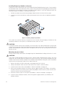
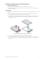
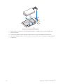
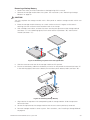
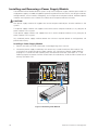
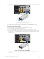
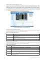
1
MAXDATA PLATINUM Modular System User’s Manual Contents Contents 1 Safety Information 7 Safety Warnings and Cautions.................................................................................................................7 Intended Application Uses.......................................................................................................................7 General Warnings.....................................................................................................................................8 Place Battery Marking.........................................................................................................................8 Site Selection...........................................................................................................................................9 Equipment Handling Practices.................................................................................................................9 Power Cord Warnings............................................................................................................................10 System Access Warnings......................................................................................................................10 Rack Mount Warnings............................................................................................................................11 Electrostatic Discharge (ESD).................................................................................................................11 Other Hazards........................................................................................................................................11 Battery Replacement.........................................................................................................................11 Cooling and Airflow...........................................................................................................................11 Laser Peripherals or Devices.............................................................................................................12 2 Server System Features 13 Front View..............................................................................................................................................14 Server Compute Module...................................................................................................................14 Storage Enclosure.............................................................................................................................14 I/O Cooling Module...........................................................................................................................14 Rear View...............................................................................................................................................15 Power Supply Module.......................................................................................................................15 I/O Module Slots...............................................................................................................................16 Front Chassis Connectors and Indicators...............................................................................................17 Server Compute Module...................................................................................................................17 Back Chassis Connectors and Indicators...............................................................................................18 Hardware Requirements........................................................................................................................18 3 Hardware Installations and Upgrades 19 Before You Begin...................................................................................................................................19 Tools and Supplies Needed...............................................................................................................19 Chassis References...........................................................................................................................19 Installing the MAXDATA PLATINUM Modular System in a Rack...........................................................19 Installation Guidelines.......................................................................................................................19 Installing Temporary Handles on System..........................................................................................20 Mounting System in Rack.................................................................................................................20 Installing and Removing Modules..........................................................................................................21 Installing and Removing the Management Module, Ethernet Switch Modules and Storage Modules21 Replacing a Management Module....................................................................................................21 Installing and Removing an Ethernet Switch Module.......................................................................23 Installing and Removing a Storage Module.......................................................................................25 Installing and Removing the Backup Battery..........................................................................................27 Installing a Backup Battery................................................................................................................27 Removing a Backup Battery..............................................................................................................29 Installing and Removing a Power Supply Module..................................................................................30 Installing a Power Supply Module.....................................................................................................30 Removing a Power Supply Module...................................................................................................31 Replacing Cooling Modules....................................................................................................................32 Replacing a Main Cooling Module.....................................................................................................32 Replacing the I/O Cooling Module.....................................................................................................33 MAXDATA PLATINUM Modular System M1 Installing and Removing Hard Drives.....................................................................................................34 Installing a Hard Drive into the Storage Bay......................................................................................34 Removing a Hard Drive from the Storage Bay..................................................................................36 Installing and Removing a Server Compute Module..............................................................................37 Installing a Server Compute Module.................................................................................................37 Removing a Server Compute Module...............................................................................................38 4 Using the Server System 39 5 Configuring the Server Chassis 41 6 Troubleshooting 75 7 Rail Kit Installation 79 8 Regulatory and Integration Information 85 Appendix A: Sicherheitshinweise 87 Appendix B: Consignes de sécurité 93 Appendix C: Informacje dotyczące bezpieczeństwa 99 Before Powering On the Server System................................................................................................39 Starting Up Server System.....................................................................................................................39 Installing an Operating System..............................................................................................................39 Monitoring the Server System...............................................................................................................40 Shutting Down the Server System.........................................................................................................40 Introduction............................................................................................................................................41 Required Configuration for Systems.................................................................................................42 Recommended Additional Configuration for Systems......................................................................42 Setting Up a Remote Connection...........................................................................................................42 Remote Client System Requirements...............................................................................................43 MAXDATA PLATINUM Modular System Control...................................................................................43 Login to the MAXDATA PLATINUM Modular System Control..........................................................43 Layout and Key Navigation Features.................................................................................................44 MAXDATA PLATINUM Modular System Control Views...................................................................46 MAXDATA PLATINUM Modular System Control Left Menu Items.......................................................48 System..............................................................................................................................................48 Reports..............................................................................................................................................65 Settings.............................................................................................................................................68 First Steps Checklist...............................................................................................................................75 Specific Issues and Corrective Actions..................................................................................................75 Chassis Fan Module Not Functioning................................................................................................75 Cannot Connect to the Management Module...................................................................................76 Cannot Connect to a Server Compute Module.................................................................................76 Cannot Connect a Server Compute Module to a Storage Module....................................................77 Diagnostic LED Information...................................................................................................................77 Prepare System......................................................................................................................................79 Prepare Rack..........................................................................................................................................79 Setting the Multi-pin Adapters for Rack Type...................................................................................79 Installing Rack Rails into Rack...........................................................................................................81 Install System in Rack............................................................................................................................83 Complete Setup.....................................................................................................................................83 Product Regulatory Compliance.............................................................................................................85 Product Safety Compliance...............................................................................................................85 Product RoHS Compliance.....................................................................................................................85 Product EMC Compliance......................................................................................................................85 Product Regulatory Compliance Markings.............................................................................................85 Electromagnetic Compatibility Notices..................................................................................................85 Europe (CE Declaration of Conformity).............................................................................................85 Contents Figures 1. MAXDATA PLATINUM Modular System.........................................................................................13 2. Front View of Server System...........................................................................................................14 3. Rear View of Server System............................................................................................................15 4. Front Chassis Connectors and Indicators.........................................................................................17 5. Rear Chassis Connectors and Indicators..........................................................................................18 6. Installing Temporary Handles...........................................................................................................20 7. Removing Management Module......................................................................................................21 8. Installing Management Module........................................................................................................22 9. Installing an Ethernet Switch Module..............................................................................................23 10.Removing an Ethernet Switch Module............................................................................................24 11.Installing a Storage Module..............................................................................................................25 12.Removing a Storage Module............................................................................................................26 13.Removing Top Cover from Storage Module.....................................................................................27 14.Installing Backup Battery..................................................................................................................28 15.Removing Top Cover from Storage Module.....................................................................................29 16.Removing Backup Battery................................................................................................................29 17.Removing Filler Module...................................................................................................................30 18.Installing Power Supply Module.......................................................................................................31 19.Removing a Power Supply Module..................................................................................................31 20.Removing a Main Cooling Module...................................................................................................32 21.Installing a Main Cooling Module.....................................................................................................33 22.Replacing an I/O Cooling Module.....................................................................................................33 23.Removing a Drive Carrier from a Drive Bay......................................................................................34 24.Installing Hard Drive into Drive Carrier.............................................................................................35 25.Installing Drive Carrier in Drive Bay..................................................................................................35 26.Removing a Drive Carrier from a Drive Bay......................................................................................36 27.Removing Hard Drive from a Drive Carrier.......................................................................................36 28.Installing a Server Compute Module................................................................................................37 29.Removing a Server Compute Module..............................................................................................38 30.MAXDATA PLATINUM Modular System Control Login...................................................................44 31.MAXDATA PLATINUM Modular System Control General Layout....................................................44 32.MAXDATA PLATINUM Modular System Control System Configuration Screen Layout.................45 33.Dashboard View...............................................................................................................................46 34.Chassis Front View...........................................................................................................................47 35.Chassis Back View...........................................................................................................................47 36.Server Compute Module View.........................................................................................................49 37.Server Action - Remove KVM & CD.................................................................................................50 38.Initial Storage Configuration Screen.................................................................................................51 39.Create Storage Pool Dialog Box.......................................................................................................52 40.Create Storage Pool Dialog Box Example........................................................................................53 41.Storage Screen with a Storage Pool Present...................................................................................53 42.Create Virtual Drive Dialog Box........................................................................................................55 43.Virtual Drive Screen..........................................................................................................................56 44.Assign Virtual Drive..........................................................................................................................57 45.Deleted Virtual Drive........................................................................................................................58 46.Physical Drives.................................................................................................................................58 47.Gigabit Ethernet Switch Module View.............................................................................................60 48.Edit Ports Dialog Box........................................................................................................................61 49.Advanced UI Screen.........................................................................................................................62 50.Storage Module View.......................................................................................................................62 51.Management Module View..............................................................................................................63 52.Storage Resource Allocation Map....................................................................................................65 53.System Events Screen.....................................................................................................................66 54.Diagnostics - Chassis System Event Log (SEL) Viewer...................................................................67 55.Diagnostics - Service Data................................................................................................................68 MAXDATA PLATINUM Modular System M1 56.Settings - Firmware Update Screen.................................................................................................69 57.Settings - Event Policies Configuration Screen................................................................................69 58.Settings - IP Configuration................................................................................................................70 59.Settings - User Account Configuration Screen.................................................................................71 60.Settings - Alert Notification Destination Configuration Screen.........................................................71 61.Settings - SNMP Configuration Screen............................................................................................72 62.Settings - System Date and Time Configuration..............................................................................73 63.Multi-pin Adapter..............................................................................................................................79 64.Removing Multi-pin Adapter from Multi-pin Bracket........................................................................80 65.Setting Multi-pin Adapter in Multi-pin Bracket.................................................................................80 66.Determining Vertical Position in Rack..............................................................................................81 67.Attaching Rack Rail to Multi-pin Bracket..........................................................................................82 68.Tightening Captive Fasteners...........................................................................................................83 Tables 1. Safety Warnings and Cautions...........................................................................................................7 2. Chassis Feature Summary...............................................................................................................13 3. Front Components...........................................................................................................................14 4. Rear Platform Features....................................................................................................................15 5. Minimum System Requirements for Remote Web Console...........................................................43 6. Server Action Menu.........................................................................................................................49 7. Server Tabs......................................................................................................................................50 8. Storage Pool Actions Menu..............................................................................................................54 9. Virtual Drive Action Menu................................................................................................................56 10.Virtual Drive Tabs.............................................................................................................................56 11.Physical Drive Action Menu.............................................................................................................59 12.Physical Drive Tabs..........................................................................................................................59 13.Switch Module Action Menu............................................................................................................60 14.Switch Module Tabs.........................................................................................................................60 15.Storage Module Action Menu..........................................................................................................63 16.Storage Module Tabs.......................................................................................................................63 17.Management Module Action Menu.................................................................................................64 18.Fans and Power Supplies Tabs........................................................................................................64 19.Diagnostic LEDs...............................................................................................................................77 20.NIC LEDs..........................................................................................................................................78 21.Product Certification Markings.........................................................................................................85 Contents 1 Safety Information This document applies to MAXDATA PLATINUM Server Boards, MAXDATA PLATINUM Server Chassis (pedestal and rack-mount) and installed peripherals. To reduce the risk of bodily injury, electrical shock, fire, and equipment damage, read this document and observe all warnings and precautions in this guide before installing or maintaining your MAXDATA PLATINUM server product. In the event of a conflict between the information in this document and information provided with the product or on the website for a particular product, the product documentation takes precedence. Your server should be integrated and serviced only by technically qualified persons. You must adhere to the guidelines in this guide and the assembly instructions in your server manuals to ensure and maintain compliance with existing product certifications and approvals. Use only the described, regulated components specified in this guide. Use of other products/components will void the UL Listing and other regulatory approvals of the product, and may result in noncompliance with product regulations in the region(s) in which the product is sold. Safety Warnings and Cautions To avoid personal injury or property damage, before you begin installing the product, read, observe, and adhere to all of the following safety instructions and information. The following safety symbols may be used throughout the documentation and may be marked on the product and/or the product packaging. Table 1. Safety Warnings and Cautions Indicates potential hazard if indicated information is ignored Indicates shock hazard that results in serious injury or death if safety instructions are not followed Indicates hot components and surfaces Indicates electrostatic discharge cautions Indicates do not touch fan blades, may result in injury Indicates to unplug all AC power cord(s) to disconnect AC power Intended Application Uses This product was evaluated as Information Technology Equipment (ITE), which may be installed in offices, schools, computer rooms, and similar commercial type locations. The suitability of this product for other product categories and environments (such as medical, industrial, residential, alarm systems, and test equipment), other than an ITE application, may require further evaluation. MAXDATA PLATINUM Modular System M1 General Warnings The power supply in this product contains no user-serviceable parts. There may be more than one supply in this product. Refer servicing only to qualified personnel. Do not attempt to modify or use the supplied AC power cord if it is not the exact type required. A product with more than one power supply will have a separate AC cord for each supply. The DC push-button on/off switch on the front panel does not turn off system AC power. To remove power from the system, you must unplug each AC power cord from the wall outlet or power supply. Ensure that the system is disconnected from its power source and from all telecommunication links, networks, and modem lines whenever the chassis cover is to be removed. This may require disconnecting multiple power cords. Do not operate the system with the cover removed. A microprocessor and heat sink may be hot if the system has been running. Also, there may be sharp pins and edges on some board and chassis parts. Contact should be made with care. Consider wearing protective gloves. Danger of explosion if the battery is incorrectly replaced. Replace only with the same or equivalent type recommended by the equipment manufacturer. Discard used batteries according to manufacturer’s instructions. Depending on the weight of the product, 4 people together should lift it. The system is designed to operate in a typical office environment. Choose a site that is: • Clean and free of airborne particles (other than normal room dust). • Well ventilated and away from sources of heat including direct sunlight. • Away from sources of vibration or physical shock. • Isolated from strong electromagnetic fields produced by electrical devices. • In regions that are susceptible to electrical storms, we recommend you plug your system into a surge suppresser and disconnect telecommunication lines to your modem during an electrical storm. • Provided with a properly grounded wall outlet. • Provided with sufficient space to access the power supply cords, because they serve as the product’s main power disconnect. Place Battery Marking There is insufficient space on this server board to provide instructions for replacing and disposing of the battery. For system safety certification, the following statement or equivalent statement may be required to be placed permanently and legibly on the chassis near the battery. CAUTION Risk of explosion if battery is incorrectly replaced. Replace with only the same or equivalent type recommended by the manufacturer. Dispose of used batteries according to the manufacturer’s instructions. Safety Information Site Selection The system is designed to operate in a typical office environment. Choose a site that is: • Clean, dry, and free of airborne particles (other than normal room dust). • Well-ventilated and away from sources of heat including direct sunlight and radiators. • Away from sources of vibration or physical shock. • Isolated from strong electromagnetic fields produced by electrical devices. • In regions that are susceptible to electrical storms, we recommend you plug your system into a surge suppresser and disconnect telecommunication lines to your modem during an electrical storm. • Provided with a properly grounded wall outlet. • Provided with sufficient space to access the power supply cord(s), because they serve as the product’s main power disconnect. Equipment Handling Practices Reduce the risk of personal injury or equipment damage: • Conform to local occupational health and safety requirements when moving and lifting equipment. • Use mechanical assistance or other suitable assistance when moving and lifting equipment. • To reduce the weight for easier handling, remove any easily detachable components. CAUTION The power button, indicated by the stand-by power marking, DOES NOT completely turn off the system AC power, 5 V standby power is active whenever the system is plugged in. To remove power from system, you must unplug the AC power cord from the wall outlet. Your system may use more than one AC power cord. Make sure all AC power cords are unplugged. Make sure the AC power cord(s) is/are unplugged before you open the chassis, or add or remove any non hot-plug components. Do not attempt to modify or use an AC power cord if it is not the exact type required. A separate AC cord is required for each system power supply. Some power supplies in MAXDATA PLATINUM Servers use Neutral Pole Fusing. To avoid risk of shock use CAUTION when working with power supplies that use Neutral Pole Fusing. The power supply in this product contains no user-serviceable parts. Do not open the power supply. Hazardous voltage, current and energy levels are present inside the power supply. Return to manufacturer for servicing. When replacing a hot-plug power supply, unplug the power cord to the power supply being replaced before removing it from the server. To avoid risk of electric shock, turn off the server and disconnect the power cord, telecommunications systems, networks, and modems attached to the server before opening it. MAXDATA PLATINUM Modular System M1 Power Cord Warnings If an AC power cord was not provided with your product, purchase one that is approved for use in your country. CAUTION To avoid electrical shock or fire, check the power cord(s) that will be used with the product as follows: • Do not attempt to modify or use the AC power cord(s) if they are not the exact type required to fit into the grounded electrical outlets • The power cord(s) must meet the following criteria: - The power cord must have an electrical rating that is greater than that of the electrical current rating marked on the product. - The power cord must have safety ground pin or contact that is suitable for the electrical outlet. • The power supply cord(s) is/are the main disconnect device to AC power. The socket outlet(s) must be near the equipment and readily accessible for disconnection. • The power supply cord(s) must be plugged into socket-outlet(s) that is /are provided with a suitable earth ground. System Access Warnings CAUTION To avoid personal injury or property damage, the following safety instructions apply whenever accessing the inside of the product: • Turn off all peripheral devices connected to this product. • Turn off the system by pressing the power button to off. • Disconnect the AC power by unplugging all AC power cords from the system or wall outlet. • Disconnect all cables and telecommunication lines that are connected to the system. • Retain all screws or other fasteners when removing access cover(s). Upon completion of accessing inside the product, refasten access cover with original screws or fasteners. • Do not access the inside of the power supply. There are no serviceable parts in the power supply. Return to manufacturer for servicing. • Power down the server and disconnect all power cords before adding or replacing any non hotplug component. • When replacing a hot-plug power supply, unplug the power cord to the power supply being replaced before removing the power supply from the server. CAUTION If the server has been running, any installed processor(s) and heat sink(s) may be hot. Unless you are adding or removing a hot-plug component, allow the system to cool before opening the covers. To avoid the possibility of coming into contact with hot component(s) during a hot-plug installation, be careful when removing or installing the hot-plug component(s). CAUTION To avoid injury do not contact moving fan blades. If your system is supplied with a guard over the fan, do not operate the system without the fan guard in place. 10 Safety Information Rack Mount Warnings The equipment rack must be anchored to an unmovable support to prevent it from tipping when a server or piece of equipment is extended from it. The equipment rack must be installed according to the rack manufacturer’s instructions. Install equipment in the rack from the bottom up, with the heaviest equipment at the bottom of the rack. Extend only one piece of equipment from the rack at a time. You are responsible for installing a main power disconnect for the entire rack unit. This main disconnect must be readily accessible, and it must be labeled as controlling power to the entire unit, not just to the server(s). To avoid risk of potential electric shock, a proper safety ground must be implemented for the rack and each piece of equipment installed in it. Electrostatic Discharge (ESD) CAUTION ESD can damage disk drives, boards, and other parts. We recommend that you perform all procedures at an ESD workstation. If one is not available, provide some ESD protection by wearing an antistatic wrist strap attached to chassis ground - any unpainted metal surface - on your server when handling parts. Always handle boards carefully. They can be extremely sensitive to ESD. Hold boards only by their edges. After removing a board from its protective wrapper or from the server, place the board component side up on a grounded, static free surface. Use a conductive foam pad if available but not the board wrapper. Do not slide board over any surface Other Hazards Battery Replacement CAUTION There is the danger of explosion if the battery is incorrectly replaced. When replacing the battery, use only the battery recommended by the equipment manufacturer. Dispose of batteries according to local ordinances and regulations. Do not attempt to recharge a battery. Do not attempt to disassemble, puncture, or otherwise damage a battery. Cooling and Airflow CAUTION Carefully route cables as directed to minimize airflow blockage and cooling problems. For proper cooling and airflow, operate the system only with the chassis covers installed. Operating the system without the covers in place can damage system parts. To install the covers: 1. Check first to make sure you have not left loose tools or parts inside the system. 2. Check that cables, add-in boards, and other components are properly installed. 3. Attach the covers to the chassis according to the product instructions. MAXDATA PLATINUM Modular System M1 11 Laser Peripherals or Devices CAUTION To avoid risk of radiation exposure and/or personal injury: • Do not open the enclosure of any laser peripheral or device. • Laser peripherals or devices are not user serviceable. • Return to manufacturer for servicing. 12 Safety Information 2 Server System Features This chapter briefly describes the main features of the MAXDATA PLATINUM Modular System. This chapter provides photographs and illustrations of the product, a features list, and diagrams showing the location of important components and connections on the server chassis. 1 I/O 2 1 2 ID 1 I/O 2 1 2 ID Figure 1. MAXDATA PLATINUM Modular System The platform features are outlined in the following table. Table 2. Chassis Feature Summary Feature Description Module bays (rear) • • • • • Module bays (front) • Six hot-plug server compute module bays • One hot-swap I/O cooling module bay • One hard drive storage enclosure bay Hard drive storage enclosure • 14 hot-swap 2.5-inch SAS hard disk drives Four hot-plug 110/220V power module bays Two hot-swap Ethernet switch module bays Two hot-swap storage module bays Two hot-swap main cooling module bays One hot-swap management module bay MAXDATA PLATINUM Modular System Control • Integrated GUI for configuration and chassis management. MAXDATA PLATINUM Modular System M1 13 Front View Figure 2 shows the front view of the platform. The front provides access to the following components. B A C Figure 2. Front View of Server System Table 3. Front Components Item Description A. Server compute modules or filler panels (six) [1 at top, 6 at bottom] B. Storage enclosure with hot-swap 2.5-inch SAS hard disk drives (14) [1 at upper left, 14 at lower right] C. I/O cooling module Server Compute Module The MAXDATA PLATINUM Modular System supports up to six server compute modules. Each server compute module is a general-purpose server built around the following minimum features: • Processor(s) • Memory • Baseboard management controller • Network interface • Storage controller See the individual MAXDATA PLATINUM 1000IM User’s Manual for model-specific information. Storage Enclosure The MAXDATA PLATINUM Modular System has an integrated 14-bay hot-swap 2.5-inch SAS hard disk drive storage enclosure. Storage is shared among all installed server compute modules. At least one Storage Module is required to access the shared storage. I/O Cooling Module The I/O cooling module consists of six fans in a hot-swap module with power and status indicators. These fans provide cooling for all I/O modules. The I/O cooling module is accessible from the front of the system even though it cools the I/O modules in the rear of the system. 14 Server System Features Rear View Figure 3 shows a rear view of the platform. The rear provides access to the following components: C A B E D Figure 3. Rear View of Server System Table 4. Rear Platform Features Item Description A. Power supply module bays (four) (as illustrated: two top bays occupied by power supply modules; two bottom bays occupied by power supply blanks) B. Main cooling module bays (two) I/O Module Slots C. Ethernet switch module slots (two) D. Storage module slots (two) E. Management module slot (one) Power Supply Module Up to four hot-swap power supply modules can be installed in the right rear of the chassis. Each supply has its own AC input power connector and is rated at 1000 watts over an input range of 100–240 VAC. Each power supply includes two fans that provide cooling for hot-swap disk drives. All four power supply bays must be populated with either a power supply module or a power supply blank. The power supply blank has two fans that ensure proper system cooling. One power supply will support one server compute module plus all other modules in the system. Two power supplies will support 2 to 3 server compute modules (in any slot) plus all other modules in the system. Three power supplies will support four to six server compute modules (in any slot) plus all other modules in the system. Any additional power supplies above the minimum required (based on configuration) will provide redundancy. MAXDATA PLATINUM Modular System M1 15 I/O Module Slots The middle-rear of the chassis can accommodate up to four expansion modules. Ethernet Switch Module One or two hot-swap Gigabit Ethernet Switch modules can be installed. Each switch has ten uplink ports and twelve internal server bay ports, two ports routed to each server compute module. One switch module is the minimum configuration for external networking; a second switch module allows for network module redundancy. Storage Module One or two hot-swap Storage Modules can be used with 14 hotswap drives in the front to support hard disk drives in the chassis. One storage module is the minimum configuration; a second storage module allows for storage module redundancy. When two storage modules are installed and one fails, drive access is maintained through the operational storage module. Management Module The Management Module is installed in the middle-rear of the chassis, between the four I/O slots. This module provides an Internet browser interface that allows the configuration and management of the entire Management Module. This module is not redundant but the system will continue to operate normally if this module fails. However, any changes to the system configuration will not be recognized until the failed management module is replaced. Main Cooling Modules Two hot-swap main cooling modules are installed on the left rear of the chassis. Each module contains a redundant fan. Main cooling modules maintain separate zones in the chassis. Both modules are required to properly cool all server compute modules. 16 Server System Features Front Chassis Connectors and Indicators A B C D Figure 4. Front Chassis Connectors and Indicators Hard Drive Carrier A. Hard drive power/activity LED – Green B. Hard drive fault LED – Amber I/O Cooling Module C. I/O cooling module power LED – Green D. I/O cooling module fault LED – Amber All indicator modes are described in “Diagnostic LED Information” on page 77. Server Compute Module See the individual MAXDATA PLATINUM 1000IM User’s Manual for model-specific information. MAXDATA PLATINUM Modular System M1 17 Back Chassis Connectors and Indicators A B C D E F G H I J P O N M L K Figure 5. Rear Chassis Connectors and Indicators Storage Module A. Storage module dirty cache LED – Green B. Storage module fault LED – Amber C. Storage module power LED – Green M. Storage module external SAS connector Ethernet Switch Module D. Ethernet switch module power LED – Green E. Ethernet switch module fault LED – Amber L. Ethernet switch module 1-Gb Ethernet connectors (10) with LEDs P. Serial cable connectors (for service only) Management Module F. Management module power LED – Green G. Management module fault LED – Amber H. Management module reset switch K. Management module NIC connectors with LEDs Power Supply Module I. Power supply module power LED – Green J. Power supply fault indicator LED – Amber N. Main cooling module fault LED – Amber O. Main cooling module power LED – Green Main Cooling Module All indicator modes are described in “Diagnostic LED Information” on page 77. Hardware Requirements To avoid integration difficulties and possible system damage, your server system must meet the requirements listed in the table under “Before Powering On the Server System” on page 39. 18 Server System Features 3 Hardware Installations and Upgrades Before You Begin Before working on your server system, review the safety and ESD information at the beginning of this manual. Tools and Supplies Needed • Phillips (cross head) screwdriver (#1 bit and #2 bit) • Needle-nosed pliers • A ruler • Pen or pencil • Anti-static wrist strap and conductive foam pad (recommended) Chassis References All references to left, right, front, top, and bottom are based on the reader facing the front of the chassis as it would be positioned for normal operation. Installing the MAXDATA PLATINUM Modular System in a Rack The MAXDATA PLATINUM Modular System is designed for fixed mount rack installation only; all service events will be performed from either the front or back of the system. CAUTION When removing the system from its packaging, DO NOT lift the system by the power supply or fan module handles. Installation Guidelines 1. Review the safety and ESD information at the beginning of this manual. 2. Two or more people are required to install the MAXDATA PLATINUM Modular System in a rack cabinet. CAUTION When lifting the system, DO NOT lift by the power supply or fan module handles. 3. All server compute modules, hard drives, power supply modules, I/O modules, and cooling modules should be removed before placing the MAXDATA PLATINUM Modular System in a rack. 4. The MAXDATA PLATINUM Modular System can only be installed in a rack cabinet with perforated front and rear doors. 5. Plan device installation starting with the bottom of the rack cabinet. 6. Do not leave unused space within the rack cabinet opening; blank filler panels must be used to fill gaps and prevent recirculation of warm air. 7. Ensure the power outlets in the rack are sufficient in quantity and load capacity to support all devices intended to be installed in the rack. MAXDATA PLATINUM Modular System M1 19 Installing Temporary Handles on System Temporary handles are provided with your MAXDATA PLATINUM Modular System. These handles are intended to aid in the movement of the system during removal from packaging and during initial configuration and installation. However, the profile of the handles is such that it prevents their use when the system is installed in a standard 19-inch rack. 1. Handles are to be mounted to the top edges of both the front and rear of the system. 2. Install front and rear handles by inserting handle tabs into chassis slots and tightening captive screws. 1 I/O 2 1 2 ID 1 I/O 2 1 2 ID Figure 6. Installing Temporary Handles The system can now be moved as required to aid in removal from packaging, installation of the remaining modules in the system, or installation of the system in a rack. CAUTION If using the handles during rack installation, the rear handles must be removed prior to setting the system on the rack rails to avoid interference of the handles with the rack. The front handles must also be removed before sliding the system completely into the rack and securing the front chassis tabs to the rack. Mounting System in Rack Please read the safety information at the beginning of this book before installing the chassis in a rack. CAUTION If you have installed temporary handles to aid in moving and/or configuring the system, you must remove the rear handles prior to setting the system on the rack rails to avoid interference of the handles with the rack. The front handles must also be removed before sliding the system completely into the rack and securing the front chassis tabs to the rack. 1. Review the safety and ESD information at the beginning of this manual. 2. Identify the location within the rack where the server system is to be installed. 3. Install the rack mount rails as described in “Rail Kit Installation” on page 79. 4. With server compute modules, hard drives, power supply modules, I/O modules, and cooling modules removed, and working with at least two people, slide the server system into the rack so that it rests on the rack mounting rails. 5. Secure the server system in the rack as described in “Rail Kit Installation” on page 79. 6. Install all server compute modules, hard drives, power supply modules, I/O modules, and cooling modules. 20 Hardware Installations and Upgrades Installing and Removing Modules 1. Review the safety and ESD information at the beginning of this manual. 2. The green color on components and labels in your chassis identifies hot-swap components. You can install or remove hot-swap modules, and hot plug server compute modules with some restrictions, while the server system is powered on. 3. You do not need to disconnect the server system from power to install or replace any of the hotswap modules; however, to avoid data corruption, you must shut down the operating system and power off the server compute module before removing it from the server system. 4. Hot-swap cooling modules must be replaced within one minute. All other hot-swap and hot-plug components must be replaced within two minutes. Server compute modules, management modules, switch modules, storage modules, power modules and cooling modules should be replaced with a like component or a filler panel within two minutes. Installing and Removing the Management Module, Ethernet Switch Modules and Storage Modules The steps for installation and removal of the management module, Ethernet switch modules, and storage modules are nearly identical; each of these devices may only be installed in a module bay that is designed to support that device type. Referring to the chassis reference section at the beginning of this section, the two bays located on the left are designed to accept one storage module in the far left bay and one Ethernet switch module in the second bay from the left. The middle bay is dedicated to the management module, and the two bays on the left are designed to accept one storage module in the far right bay and one Ethernet switch module in the second bay from the right. Replacing a Management Module The MAXDATA PLATINUM Modular System ships with a management module preinstalled. If necessary, the management module may be removed and replaced by following these steps: 1. Review the safety and ESD information at the beginning of this manual. 2. Remove the Ethernet cable from the management module. 3. Press the retention latch (see letter “A” in the following figure) to release the retention lever. Rotate the lever out and away from the module bay (see letter “B”) and pull the module straight out the back of the chassis (see letter “C”). C A B Figure 7. Removing Management Module MAXDATA PLATINUM Modular System M1 21 4. Release and rotate the module retention lever out and away from the replacement management module (see letter “A” in the following figure). Slide the replacement management module into the management module bay (see letter “B”) until the bottom of the retention lever engages with the module bay. B A Figure 8. Installing Management Module 5. Rotate the lever handle in toward the module bay until it is latched. 6. Reconnect the Ethernet management port to the management network. 22 Hardware Installations and Upgrades Installing and Removing an Ethernet Switch Module The MAXDATA PLATINUM Modular System ships with one Ethernet switch module pre-installed; optionally, a second switch module may be installed in the second switch module bay. Installing an Ethernet Switch Module 1. Review the safety and ESD information at the beginning of this manual. 2. Locate an available switch bay and remove any installed module or filler panel. 3. Release and rotate the module retention lever out and away from the switch module (see letter “A” in the following figure). Slide the switch module into the selected module bay (see letter “B”) until the bottom of the retention lever engages the bay. B A Figure 9. Installing an Ethernet Switch Module 4. Rotate the lever handle in toward the module bay until it is latched. 5. Connect one or more Ethernet switch ports to your network as is appropriate. MAXDATA PLATINUM Modular System M1 23 Removing an Ethernet Switch Module 1. Review the safety and ESD information at the beginning of this manual. 2. Remove and label the connected Ethernet cables, as necessary. 3. Press the retention latch (see letter “A” in the following figure) to release the retention lever. Rotate the lever out and away from the module bay (see letter “B”) and pull the module straight out the back of the chassis (see letter “C”). C A B Figure 10. Removing an Ethernet Switch Module 4. Replace the switch module with a filler panel or another Ethernet switch module within two minutes. 24 Hardware Installations and Upgrades Installing and Removing a Storage Module The MAXDATA PLATINUM Modular System ships with one storage module preinstalled; optionally, a second storage module may be installed in the open storage module bay. Installing a Storage Module 1. Review the safety and ESD information at the beginning of this manual. 2. Locate an available storage module bay and remove any installed module or filler panel. 3. Release and rotate the module retention lever out and away from the storage module (see letter “A” in the following figure). Slide the storage module into the selected module bay (see letter “B”) until the bottom of the retention lever engages with the module bay. B A Figure 11. Installing a Storage Module 4. Rotate the lever handle in toward the module bay until it latches. MAXDATA PLATINUM Modular System M1 25 Removing a Storage Module 1. Review the safety and ESD information at the beginning of this manual. 2. Press the retention lever latch button to release the retention lever (see letter “A” in the following figure). Rotate the lever out and away from the module bay (see letter “B”) and pull the storage module straight out the back of the chassis (see letter “C”). CAUTION You must replace the storage module with a filler panel or another storage module within two minutes. C A B Figure 12. Removing a Storage Module 3. Replace the storage module with a filler panel or another storage module within two minutes. 26 Hardware Installations and Upgrades Installing and Removing the Backup Battery Installing a Backup Battery 1. Review the safety and ESD information at the beginning of this manual. 2. Remove the storage module from the system. For instructions, see “Removing a Storage Module” on page 26. CAUTION You must replace the storage module with a filler panel or another storage module within two minutes. 3. Place the storage module sideways on a work surface so that it’s largest surface area is touching the work surface and the retention lever is on the top. 4. With a Phillips screwdriver, remove the screw securing the top cover to the storage module (see letter “A” in the following figure). Push cover rearward (see letter “B”) and lift off of module (see letter “C”). C B A Figure 13. Removing Top Cover from Storage Module 5. Slide the cover towards the rear of the storage module and lift upward. 6. Install the backup battery in the black plastic battery holder (see letter “A” in the following figure). Connect the battery cable to the battery connector on the printed circuit board (see letter “B”). MAXDATA PLATINUM Modular System M1 27 A B Figure 14. Installing Backup Battery 7. Align notches in top cover with corresponding tabs in storage module. Slide the top cover forward to close. 8. Secure the top cover to the storage module with the two screws previously removed. 9. Re-install storage module in server system. For instructions, see “Installing a Storage Module” on page 25. 28 Hardware Installations and Upgrades Removing a Backup Battery 1. Review the safety and ESD information at the beginning of this manual. 2. Remove the storage module from the system. For instructions, see “Removing a Storage Module” on page 26. CAUTION You must replace the storage module with a filler panel or another storage module within two minutes. 3. Place the storage module sideways on a work surface so that it’s largest surface area is touching the work surface and the retention lever is on the top. 4. With a Phillips screwdriver, remove the screw securing the top cover to the storage module (see letter “A” in the following figure). Push cover rearward (see letter “B”) and lift off of module (see letter “C”). C B A Figure 15. Removing Top Cover from Storage Module 5. Slide the cover towards rear of the storage module and lift upward. 6. Disconnect the battery cable from the battery connector on the printed circuit board (see letter “A” in the following figure). Remove the battery from the black plastic battery holder (see letter “B”). B A Figure 16. Removing Backup Battery 7. Align notches in top cover with corresponding tabs in storage module. Slide the top cover forward to close. 8. Secure the top cover to the storage module with the two screws previously removed. 9. Re-install storage module in server system. For instructions, see “Installing a Storage Module” on page 25. MAXDATA PLATINUM Modular System M1 29 Installing and Removing a Power Supply Module The MAXDATA PLATINUM Modular System ships with two power supply modules pre-installed. A single power supply is suitable to support the power requirement for the chassis, including fan modules, storage module, switch module, storage bay, and a single server compute module. Additional power modules are required as the number of installed server compute modules increases. CAUTION One power supply module will support one server compute module plus all other modules in the system. Two power supply modules will support two to three server compute modules (in any slot) plus all other modules in the system. Three power supply modules will support four to six server compute modules (in any slot) plus all other modules in the system. Any additional power supply modules above the minimum required (based on configuration) will provide redundancy. Installing a Power Supply Module 1. Review the safety and ESD information at the beginning of this manual. 2. Locate the power supply module bay and remove any installed module or filler module. For instructions on removing a power supply module, see “Removing a Power Supply Module” on page 31. To remove a filler module, press the retention lever latch (see letter “A” in the following figure) to release the filler module from the module bay. Slide the filler module out of the bay (see letter “B”). B A Figure 17. Removing Filler Module 30 Hardware Installations and Upgrades 3. Slide the power supply module into the power supply module bay until the retention latch engages. B A Figure 18. Installing Power Supply Module 4. Connect a power cable from the power supply module to an appropriate power source. Removing a Power Supply Module 1. Review the safety and ESD information at the beginning of this manual. 2. Locate the power supply module to be removed. 3. Remove the power cord from both the power supply module and the power source. 4. Press the power supply module retention latch to release the power supply module from the bay (see letter “A” in the following figure). Slide the power supply module out of the module bay (see letter “B”). Figure 19. Removing a Power Supply Module 5. Replace the power supply module with a filler panel or another power supply module within two minutes. MAXDATA PLATINUM Modular System M1 31 Replacing Cooling Modules The MAXDATA PLATINUM Modular System ships with two main cooling modules pre-installed at the back of the chassis and one I/O cooling module at the front. Replacing a Main Cooling Module 1. Review the safety and ESD information at the beginning of this manual. 2. Locate the main cooling module to be replaced. 3. Press the main cooling module retention clip to release the main cooling module from the module bay. 4. Slide the main cooling module out of the module bay. CAUTION Replace the cooling module with another cooling module within two minutes. B A Figure 20. Removing a Main Cooling Module 5. Slide the replacement cooling module into the unoccupied cooling module bay (see letter “C”) until the retention latch engages. 32 Hardware Installations and Upgrades Figure 21. Installing a Main Cooling Module Replacing the I/O Cooling Module 1. Review the safety and ESD information at the beginning of this manual. 2. Press the I/O cooling module retention latch to release the I/O cooling module from the module bay (see letter “A” in the following figure). Slide the I/O cooling module out of the module bay (see letter “B”). Slide the replacement I/O cooling module into the vacant module bay (see letter “C”) until the retention latch engages. CAUTION Replace the cooling module with another cooling module within two minutes. C B A Figure 22. Replacing an I/O Cooling Module MAXDATA PLATINUM Modular System M1 33 Installing and Removing Hard Drives The MAXDATA PLATINUM Modular System provides storage for installed server compute modules by way of an on-board storage bay combined with a storage management module. The on-board storage bay supports the installation of up to 14 hotswap 2.5-inch SAS hard drives that are configured through the integrated MAXDATA PLATINUM Modular System Control software. Refer to “Configuring the Server Chassis” on page 41 for more information. CAUTION Only hard drives validated for use in the MAXDATA PLATINUM Modular System should be installed. Installing a Hard Drive into the Storage Bay 1. Review the safety and ESD information at the beginning of this manual. 2. Press the retaining lever on an available drive carrier to release the drive carrier from the drive bay (see letter “A” in the following figure). Remove the drive carrier from the drive bay (see letter “B”). B A Figure 23. Removing a Drive Carrier from a Drive Bay 3. With a Phillips screwdriver, remove the four screws securing the filler panel to the drive carrier. 34 Hardware Installations and Upgrades 4. Attach hard drive to drive carrier, using the four screws removed in the previous step. Figure 24. Installing Hard Drive into Drive Carrier 5. With the drive carrier retaining lever in the open position (see letter “A” in the following figure), carefully slide the drive carrier into the drive bay until it is fully seated and the retaining lever starts to engage. Press firmly to latch the retaining lever (see letter “B”). A B Figure 25. Installing Drive Carrier in Drive Bay MAXDATA PLATINUM Modular System M1 35 Removing a Hard Drive from the Storage Bay 1. Review the safety and ESD information at the beginning of this manual. 2. To avoid data corruption, ensure that the drive you intend to remove is not online and actively providing data storage to any of the installed server compute modules. 3. Press the retaining lever on the selected drive carrier to release the drive carrier from the drive bay (see letter “A” in the following figure). Remove the drive carrier from the drive bay (see letter “B”). B A Figure 26. Removing a Drive Carrier from a Drive Bay 4. With a Phillips screwdriver, remove the four screws securing the hard drive to the drive carrier. Place the hard drive in an anti-static container or bag. Figure 27. Removing Hard Drive from a Drive Carrier 5. Install either another hot-swap hard drive or a filler blank in the drive carrier. Install the drive carrier into the empty drive bay within two minutes; this step is required to maintain proper airflow throughout the chassis and to ensure proper system cooling. 36 Hardware Installations and Upgrades Installing and Removing a Server Compute Module Installing a Server Compute Module 1. Review the safety and ESD information at the beginning of this manual. 2. If you have not done so already, install any necessary options, such as processor and memory, in the server compute module. CAUTION The top cover is a required component of the server compute module assembly. Do not attempt to insert a server compute module into the chassis without ensuring an installed top cover is in place. 3. Make sure the release handles on the server compute module are in the open position (see letter “A” in the following figure). Insert the server compute module into an open slot in the chassis and slide it in until it stops. 1 I/O 2 1 2 ID B A 1 I/O 2 1 2 A ID Figure 28. Installing a Server Compute Module 4. Close the release handles on the front of the server compute module. MAXDATA PLATINUM Modular System M1 37 Removing a Server Compute Module 1. Review the safety and ESD information at the beginning of this manual. 2. If the server compute module is operating, shut down the operating system and power it down. 3. Open the two release handles at the front of the server compute module (see letter “A” in the following figure) and pull the server compute module out of the server system (see letter “B”). 1 I/O 2 1 2 ID B A 1 I/O 2 1 2 A ID Figure 29. Removing a Server Compute Module 4. Place either a filler or another server compute module in the bay within two minutes. This step is required to maintain proper airflow throughout the server system and to ensure proper system cooling. 38 Hardware Installations and Upgrades 4 Using the Server System Before Powering On the Server System The minimum required hardware to power up the MAXDATA PLATINUM Modular System is listed in the following table Component Quantity/Location Ethernet switch module 1 in slot SWM1 Storage module 1 in slot SCM1 Management module 1 in slot CMM Power supply module 1 in power supply bay 1 Power supply blank 3 in power supply bays 2, 3 and 4 I/O cooling module 1 Main cooling module 2 in main cooling bays 1 and 2 Server Compute Module MAXDATA PLATINUM 1000IM 1 in compute module slot 1 Server compute module blanks 5 in compute module slots 2, 3, 4, 5, and 6 Starting Up Server System The MAXDATA PLATINUM Modular System does not have a power switch. When the chassis has at least one power supply with power cord plugged into an appropriate electrical outlet, standby power is available. With standby current, a user can remotely connect to the management module and/or power on a server compute module. Each server compute module has a front panel power switch. Refer to the MAXDATA PLATINUM 1000IM User’s Manual for more information. Installing an Operating System Before installing an operating system, you must first configure storage and networking via the management module’s graphical user interface (GUI). One possible way to install an operating system is as follows: 1. Connect a remote client machine to the management module in the MAXDATA PLATINUM Modular System via a cross-over cable. 2. Connect a video monitor and USB mouse and keyboard to the front of the server compute module. 3. Connect a USB CD-ROM/DVD-ROM drive to the server compute module. 4. From the remote client machine, log into the management module and configure storage and (optionally) networking for the server compute module. 5. Power on the CD-ROM/DVDROM drive and insert the operating system install media. 6. Power on the server compute module and install the operating system. Refer to “Configuring the Server Chassis” on page 41 for configuration details. MAXDATA PLATINUM Modular System M1 39 Monitoring the Server System The management module reports complete system health. From a remote client, an IT administrator can easily monitor the state of the server system. Refer to “Configuring the Server Chassis” on page 41 for more details. Shutting Down the Server System To remove power from the MAXDATA PLATINUM Modular System, you must first properly power down all server compute modules. Next, disconnect all power cables from the power source. Refer to the individual MAXDATA PLATINUM 1000IM User’s Manual for more information on powering down the server compute module(s). 40 Using the Server System 5 Configuring the Server Chassis This section provides an overview of the MAXDATA PLATINUM Modular System Control for the MAXDATA PLATINUM Modular System. It covers initial required configuration steps as well as how to launch and navigate the MAXDATA PLATINUM Modular System Control User Interface (UI). Introduction The Management Module provides a simple and intuitive browser-based graphical user interface that IT administrators can use to monitor and configure the MAXDATA PLATINUM Modular System. This GUI is referred to as the MAXDATA PLATINUM Modular System Control User Interface (UI). No CDs or additional installation steps are required to use the UI. To initially launch the UI and configure the system hardware, a default static IP address and user account are provided. Once logged into the UI, IT administrators can: • Quickly access system and component information. • Configure and manage storage sub-systems, including but not limited to: – Create, delete and/or rename a storage pool – Create, delete, rename and/or reassign a virtual drive to a server – Create or delete hot spares • Configure and manage switch modules, including but not limited to: – Configure VLAN and port settings – Reset switch module – Launch an Advanced UI for additional switch configuration features • Quickly view hardware inventory, system event logs, storage allocation and system configuration reports. • Easily view current status for all hardware components (servers, hard drives, switch modules, storage modules, management module, cooling modules, and power modules). • Configure common settings, such as: – View and modify the IP address assigned to the management module. – Configure alert notification destinations and policies – Manage MAXDATA PLATINUM Modular System Control user accounts – Update system firmware MAXDATA PLATINUM Modular System M1 41 Required Configuration for Systems Systems ship integrated with current firmware installed with the exception of the server compute modules, which ship separately. To configure the system, install the server compute modules into the chassis and then assign storage to a server using the MAXDATA PLATINUM Modular System Control. This requires the creation of a storage pool, a virtual drive and assignment of the virtual drive to a server in order to install an operating system. Refer to “Storage Configuration” on page 51 for more information. Recommended Additional Configuration for Systems The following items are recommendations only; they are not required: 1. For security, it is recommended that you change the default login name and password. Refer to “User Accounts” on page 71 for more information. 2. Change the management module default static IP address if more than one MAXDATA PLATINUM Modular System is present on the network, or if the default management module IP address cannot be accessed in the installed network environment. Refer to “IP Configuration” on page 70 for more information. 3. Check system health and view any warning or critical event entries to help troubleshoot issues. Refer to “System Events” on page 66 for more information. 4. Update system firmware and software as needed. Refer to “Alert Notifications” on page 71 for more information. Setting Up a Remote Connection Illustrated below are two recommended options for connecting a client system to the Management Module in order to launch the MAXDATA PLATINUM Modular System Control UI. Before connecting the remote system, ensure all hardware components (servers, hard drives, switch modules, storage modules, the management module, cooling modules, and power modules) are installed in the MAXDATA PLATINUM Modular System. Option 1: Connect the client system and the Management Module to an external switch using two Ethernet cables, as illustrated in the following image. Switch Option 2: Connect the client system directly to the Management Module using a cross-over cable, as illustrated in the following image. Cross-over Cable 42 Configuring the Server Chassis Remote Client System Requirements This section describes the minimum system requirements for a client computer that is accessing the MAXDATA PLATINUM Modular System Control user interface through a web browser. Table 5. Minimum System Requirements for Remote Web Console Requirement Remote Web Consoles/Clients Operating System Any operating system that supports Microsoft Internet Explorer or Mozilla Firefox. Web Browser Microsoft Internet Explorer (6 or 7) or Mozilla Firefox (version 2.0 or later) NOTE: Refer to the Release Notes for more information on web browser support and feature functionality. Browser Plug-ins Adobe Flash Player version 9 and Java SE Runtime Environment 6, Update 1 Network Stack TCP/IP Network Stack Download Browser Plug-ins Download the latest required Microsoft Internet Explorer and Mozilla Firefox plug-ins at: • Adobe Flash Player: http://www.adobe.com/products/flashplayer/ • Java SE Runtime Environment 6, Update 1: http://www.java.sun.com/javase/downloads/index.jsp MAXDATA PLATINUM Modular System Control Login to the MAXDATA PLATINUM Modular System Control To launch the MAXDATA PLATINUM Modular System Control, open a browser session on the remote client system. Microsoft Internet Explorer 6 is the recommended browser interface for the Silver release. Refer to the Release Notes and the weekly technical updates for more information on supported web browsers and known issues. Enter the Management Module default static IP address (192.168.150.150) in the address bar of the web browser. The login screen (illustrated below) will be displayed. An administrator user account is enabled for the Silver systems. This default administrator account provides access to all available management configuration settings and actions. User Account information: – Username: admin – Password: admin CAUTION Username and password are case sensitive. MAXDATA PLATINUM Modular System M1 43 A MAXDATA PLATINUM Modular System Control B C Figure 30. MAXDATA PLATINUM Modular System Control Login A Enter Management Module IP Address, 192.168.150.150 B Enter Default Username (admin) C Enter Default Password (admin Layout and Key Navigation Features The MAXDATA PLATINUM Modular System Control interface simplifies system configuration and management through the use of navigation and common layouts. The general screen layout consists of a top menu, left menu and main body. The top menu provides quick access to multiple system views. The left navigation menu provides access to system configuration screens, reports and general setting configuration screens. The main body provides the content for the selected view or screen. Top Menu Left Navigation Main Body Figure 31. MAXDATA PLATINUM Modular System Control General Layout The system configuration screens are designed to present all available information and actions for a selected system component in the main body of the interface. The following image illustrates the layout and types of information presented on the system configuration screens. 44 Configuring the Server Chassis O R G D S A B C O I E P J F N L H M K Figure 32. MAXDATA PLATINUM Modular System Control System Configuration Screen Layout A. Current User B. Logoff C. Help D. E. F. G. H. I. J. K. General Navigation Displays username for the currently logged in user. Ends current session and returns to Login screen. MAXDATA PLATINUM Modular System Control UI Help Top Menu Tabs Quickly switches between key sections of the MAXDATA PLATINUM Modular System Control. Left Navigation Provides direct links to configure and manage individual hardware compoMenu nents. Main Body Displays content for selected menu item or view. For the system items, the main body is divided into four panes: the system graphic, action menu, context sensitive help, and informational tabs. System Screen Layout System Graphic Interactive visual representation of the current state of the system hardware. By selecting a system component from the chassis graphic, the content changes in the main body to display all available actions and information for the selected component. Change Chassis Switches between the front and back views of the system chassis. Click the over View arrow. Action Menu Displays all available actions for the selected chassis component. Context Sensitive Help Informational Tabs Quick tips and links to context sensitive help for the selected component. Displays detailed information, including, but not limited to, current status, configuration and events for the selected component. Component Health and State Icons L. Information Icon – hover over icon to view component summary information. M. Health Icon - health OK N. Health Icon – warning; hover over icon to view component summary information. O. Health Icon – critical; hover over icon to view component summary information. P. Storage Pool - indicates drive is included in an existing storage pool. Q. Dedicated Hot Spare Icon - indicates hard drives that have been designated as designated hot spares to specific storage pools. Hover over icon to view component summary information. Global Hot Spare Icon – indicates hard drives that have been designated as global hot spares. Hover over icon to view component summary information. Server is powered off. R. S. MAXDATA PLATINUM Modular System M1 45 MAXDATA PLATINUM Modular System Control Views You can quickly switch between different system views from anywhere in the interface by selecting one of the top menu tabs. The top menu tabs are located on the lower right side of the banner. These tabs provide quick access to the Dashboard, Chassis Front, Chassis Back, Storage and System Event views. Dashboard The Dashboard view is displayed by default after successfully logging into the MAXDATA PLATINUM Modular System Control UI. It provides an interactive snapshot of the overall system and component health, as well as a list of all required actions and critical events. To get additional information about the information and status presented on the dashboard, move the mouse over the component or icon to view summary information, or click the component to be redirected to the component screen for detailed information and available actions. The Dashboard consists of the following five main areas: 1. Required Actions – Displays a list of all required actions. Required actions include, but are not limited to, initial system configuration steps, steps to replace a failed component, or steps to resolve a system error. The actions are listed as links that direct the IT administrator to the appropriate screen to complete the required action. 2. System Health – The system health box lists all possible system components with a visual health icon indicator. Moving the mouse over either the component name or health icon will display summary information, including whether the component is present or not present in the system, its current health and a component description. To view detailed information and available actions for any component, click the component name to be redirected to the specific component configuration screen. 3. Power Load – Quickly enables the IT administrator to view the current power consumption of the system. If the arrows are in the green area of the indicator bar, power redundancy is enabled. The yellow area of the indicator bar shows nonredundant power. The red area indicates a critical state. 4. Temperature – Displays the current system temperature. 5. Recent Critical Events – Displays all recent (unacknowledged) critical events and a link to View All Events. The View All Events link redirects the IT administrator to the Events view. Figure 33. Dashboard View 46 Configuring the Server Chassis Chassis Front The Chassis Front view provides an accurate visual view of the front of the chassis, which includes all servers, hard drives and the I/O fan. This real-time view enables an IT administrator to quickly view the current health, as well as determine which components are present or not present. The icons present on each of the components indicate the current health, as well as provide additional information regarding power state and role. By hovering over the component icon, a brief summary of the current health, state and component description is displayed in a pop-up box. The Chassis Front view enables an IT administrator to select the component he/she is most interested in. By default, no components are selected on the chassis in this view. Figure 34. Chassis Front View Chassis Back The Chassis Back view provides an accurate visual view of the back of the chassis, which includes the management module, switch modules, storage controller modules, power supplies and fans. This real-time view enables the IT administrator to quickly view the current health, as well as determine which components are present or not present. The icons present on each of the components indicate the current health. By hovering over the component icon, a brief summary of the current health, state and component description is displayed in a pop-up box. The Chassis Back view enables an IT administrator to select the component he/she is most interested in. By default, no components are selected on the chassis in this view. Figure 35. Chassis Back View MAXDATA PLATINUM Modular System M1 47 Storage Selecting the Storage tab displays the storage configuration screen. This screen enables an IT administrator to quickly group drives, create and assign virtual drives to servers, assign hot spare drives, as well as view health, status and product details. For information on how to perform these actions and more, refer to “Storage Configuration” on page 51. Switch Selecting the Switch tab displays the Gigabit Ethernet Switch configuration screen. This screen enables an IT administrator to quickly configure virtual LANs (VLANs), modify port settings, launch an advanced configuration UI, as well as view health, status and product details. For information on how to perform these actions and more, refer to “Gigabit Ethernet Switch Module 1 and 2” on page 60. Events The Events screen contains a table of all open and unacknowledged system events. This enables an IT administrator to quickly view and acknowledge new events for all system components in a single location. For more information on how to use the Events screen, refer to “System Events” on page 66. Help The Help link located at the top right of the banner opens the MAXDATA PLATINUM Modular System Control Help in a new window. Use the table of contents to quickly access help and tips for specific screens and functions. Log Off The Log Off link is located at the top right of the banner. Clicking it ends the current MAXDATA PLATINUM Modular System Control session and returns the user to the login screen. MAXDATA PLATINUM Modular System Control Left Menu Items The left navigation menu provides quick access to specific hardware configuration screens, reports and setting configuration screens. The following sections provide additional information for each menu item. System The System group enables IT administrators to quickly configure and view the most commonly accessed components (server compute modules, storage modules, and switch modules). When a system component is selected, the content in the action box, help box and informational tabs change to reflect the current actions and information for the selected component. 48 Configuring the Server Chassis Server Compute Module To view current status, available actions and product details for all installed Server Compute Modules, select a specific server from the Chassis Front, or select Servers from the System left navigation menu. The selected server will be highlighted on the system graphic. The action box, help box and informational tabs will update to provide all available actions and information for the selected server. To view a brief summary of current health, power state and server description, move the mouse over the component icon and a pop-up box is displayed with this information. Figure 36. Server Compute Module View The following information and actions are available for a selected server. Server Compute Module Actions The actions available for a selected server are displayed to the right of the system graphic. For a description of these actions, refer to the following table. Table 6. Server Action Menu Action Menu Item Description Power On (if Off) Allows the user to remotely power on the selected server. Power Off (if On) Allows the user to remotely power off the selected server. The following two options are presented in a pop-up menu when Power Off is selected: • Graceful: Ends the current operating system session on the selected server before powering off the server. • Forced: Bypasses the shut down of the operating system and immediately powers down the server. NOTE: A “Forced” Power Off could result in a loss of data and/or damage to the server. It is hightly recommended to use the “Graceful” option under normal circumstances. Reset Allows the user to remotely reset the selected server. Identify Illuminates the server ID LED, which enables easy onsite identification of a selected server. Remote Serial Console Starts a Remote Serial Console session in a new window with the selected server. Remote KVM & CD Opens a new window, allowing an IT administrator to use remote keyboard, video, and mouse (KVM) and media to monitor and manage the selected server remotely. Typical tasks performed via a remote KVM &CD session, include, but are not limited to: – Remotely install/uninstall operating systems, applications or software updates/ patches – Remotely monitor the operating system or application running on the server MAXDATA PLATINUM Modular System M1 49 Server Compute Module Details The tabs displayed below the system graphic provide detailed information on the selected server. For a description of these tabs, refer to the following table. Table 7. Server Tabs Tab Heading Description General The General tab displays: • Current status of the selected server (i.e., health, power state, etc.) • Product data information (i.e., manufacturer, model number, serial number, firmware versions, etc.) Events Displays all system events for the selected server. Sensors Displays current sensor information. Virtual Drives Displays a detailed table of all virtual drives assigned to the selected server. The table provides the following details: Name, Size, RAID Level, Status, Drive Number and Assigned Server. Server Compute Module Help To quickly access additional help regarding the Server Compute Module screen, actions, and tabs, click on the Get Help button in the Server help box located under the actions. Remote KVM & CD Remote KVM & CD enable the IT administrator to remotely view, monitor and manage the server’s pre-operating system environment, as well as install and manage the operating system and applications using a remote console system. This is the preferred method to install an operating system or application on a selected server. A single KVM & CD session is supported per server. Limit is six KVM & CD sessions per user account at a given time Steps to Install an Operating System 1. Configure Storage and assign a virtual drive to the target server. 2. Select the target server. Server must be present in the system to install an operating system. 3. Select the KVM & CD action. 4. Click Apply to start a Remote Keyboard, Video, Mouse (KVM) with CD redirection on the target server. 5. Accept dialog boxes to open the KVM session in a new window. 6. The following KVM window should display. Figure 37. Server Action - Remove KVM & CD 50 Configuring the Server Chassis 7. Select Start Redirection from the Redirection menu. 8. Select color depth when prompted. 9. The KVM session should start successfully. 10.To install an operating system from a CD, insert the CD into the remote console’s CDROM drive and select CD from the Devices menu. Storage Configuration This section provides information on creating an initial storage pool, creating an initial virtual drive and mapping the virtual drive to a server. Once a virtual drive is mapped to a server, an operating system can be installed. To configure storage, select Storage from the top menu or from the left navigation menu. The first time the storage configuration screen is displayed, no storage pools or virtual drives are present. The storage screen looks similar to the following image. Figure 38. Initial Storage Configuration Screen MAXDATA PLATINUM Modular System M1 51 Create a Storage Pool The first step in assigning storage to a server is to create a storage pool or group of drives. Once a storage pool is created, virtual drives are created within the storage pool and assigned to a server. To assign one or more drives to a storage pool, select the action menu item “Create Storage Pool”. The following dialog box appears. Figure 39. Create Storage Pool Dialog Box Select available drives for a storage pool. Hard drives that are either included in an existing storage pool or are configured as a hot spare drive are not selectable on this screen. Unavailable drives will be displayed as darker than the available hard drives and will not have the drive size displayed on the image. Selected drives are highlighted in green with the drive size displayed on the individual drive similar to the following image. The RAID level options are determined based on the number of hard drives selected for the storage pool. For example, selecting four drives will show RAID levels 0, 1, 5, 6 and 10. RAID levels that are not available will be displayed as light gray text. It is important to note that RAID level is not assigned to a storage pool. It is, however, assigned to the virtual drives within a storage pool. This enables a single storage pool to support many virtual drives with different RAID levels. After selecting the drives for the storage pool, enter a name or label for this storage pool and click Create to continue. 52 Configuring the Server Chassis The following image shows multiple drives selected in the dialog box. Figure 40. Create Storage Pool Dialog Box Example Once a storage pool has been created, the Storage screen will change to highlight the newly created storage pool. The action box, help box and informational tabs will update to provide all available actions and information for the selected storage pool. Current health and product summary is quickly available by moving the mouse over the Health/Information icon located on the selected storage pool. The following image displays the storage screen once a storage pool is present. Figure 41. Storage Screen with a Storage Pool Present MAXDATA PLATINUM Modular System M1 53 Storage Pool Actions The Storage Pool Actions displayed to the right of the system graphic enable an IT administrator to modify existing storage pools, remotely identify drives contained in a storage pool and create virtual drives. For a complete list of actions, refer to the following table. Table 8. Storage Pool Actions Menu Global Action Menu Item Description Designate one or more drives as a storage pool. Global storage actions are available at all times on the storage screen. Create Storage Pool Selected Storage Pool Action Menu Items Description Rename Rename an existing storage pool. A dialog box will be displayed prompting the user for the new storage pool name. Delete Delete an existing storage pool. This action will delete all virtual drives contained in the selected storage pool and release the drives for future storage pool configuration. ALL DATA WILL BE LOST. Identify Illuminates the hard drive ID LED, which enables easy onsite identification of the drives included in the selected storage pool. Create Virtual Drive A virtual drive is assigned a name, RAID level, size and server. Once a virtual drive is created, an operating system can be installed. Global Action Menu Item Description Expand Storage Pool Allows the user to add one or more physical drives to an existing storage pool to increase available space. Prepare for Transport Prepares drives for removal from system. Storage Pool Details The tabs displayed below the system graphic provide detailed information on the selected storage pool. For a description of these tabs, refer to the following table. Table 6. Storage Pool Tabs Tab Heading Description General The General tab displays: • Current status of the storage pool (i.e., status, health, operation state) • Storage pool configuration data (i.e., storage pool ID, name, total managed space, total unallocated space, number of physical and virtual drives included in the selected storage pool) Events Displays all system events for the selected storage pool. Physical Drives Displays a table with detailed information on the physical drives included in the selected storage pool (i.e., Drive number, Manufacturer, Product ID, Serial Number, Firmware Revision, Size, Status). Virtual Drives Displays a table with detailed information on all virtual drives contained within the selected storage pool. The table provides the following details: Name, Size, RAID Level, Status, Drive Number, and Assigned Server. Spares Displays a table with detailed information on all hot spare drives. The table includes the following information: Drive Number, Role (Global versus Dedicated), Manufacturer, Product ID, Serial Number, Firmware Revision, Size and Status. Background Tasks Displays status and state of current tasks, such as Predictive Data Migrations and Media Patrol. Storage Pool Help To quickly access additional help regarding the storage pool screen, actions, and tabs, click on the Get Help button in the Storage Pool help box located under the actions. 54 Configuring the Server Chassis Create a Virtual Drive Once a storage pool has been created, the next step is to create a virtual drive. Key benefits of virtual drives are: • Virtual drives can be quickly reassigned to different servers with a couple of mouse clicks in the MAXDATA PLATINUM Modular System Control UI without powering down the server or storage pool. • Virtual drives in a single storage pool can be set to any RAID level that is supported by the selected storage pool. The steps to create a virtual drive are as follows: 1. Select the existing storage pool, which will contain the virtual drive. 2. Select Create Virtual Drive from the storage pool action menu. The following dialog box will be displayed. Figure 42. Create Virtual Drive Dialog Box 3. Enter a name for the virtual drive. 4. Select the RAID level for the virtual drive from the drop-down box. The options available in the drop-down box are determined by the number of drives in the selected storage pool. 5. Enter the size for the virtual drive. Depending on the RAID level selected, the maximum size displayed may change (i.e., if mirroring is selected). 6. Assign or map the virtual drive to a server. A virtual drive can be assigned to any of the six server slots. A server does not have to be present in the MAXDATA PLATINUM Modular System for selection. This enables an IT administrator to assign virtual drives to servers that will be added to the system. 7. Select the “Drive Position” for the virtual drive. The drive position sets the drive number for this server. The drop-down box will show all available drive numbers (0 through 127). 8. Click Apply to create the virtual drive and return to the main Storage screen. 9. The virtual drive created will be displayed as a volume in the selected storage pool on the main storage screen. Depending on the RAID level selected, the virtual drive may continue to synchronize after it is created and displayed on the storage screen. To view the current status of the virtual drive, select the General, Virtual Drive or Background tasks tab to view more information about the virtual drive created. MAXDATA PLATINUM Modular System M1 55 Once a virtual drive is created and selected, the action menu and tabs change to display all available actions and details for the selected virtual drive. The following image shows the storage screen with a virtual drive selected. Figure 43. Virtual Drive Screen Virtual Drive Actions The actions available for a selected virtual drive are displayed to the right of the system graphic. For a description of these actions, refer to the following table. Table 9. Virtual Drive Action Menu Action Menu Item Description Assign This action enables the IT administrator to assign an existing virtual drive to a different server, change the current drive assignment for a server, or assign the virtual drive to no server. Rename Rename an existing virtual name. A dialog box will be displayed prompting the IT administrator for the new virtual drive name. Delete Delete an existing virtual drive. This action will delete the selected virtual drive. ALL DATA WILL BE LOST. Virtual Drive Details The tabs displayed below the system graphic provide detailed information on the selected virtual drive. For a description of these tabs, refer to the following table. Table 10.Virtual Drive Tabs Tab Heading Description General The General tab displays a table with the following information: • Current status of the virtual drive (i.e., status, health, operation state) • Virtual drive configuration data (i.e., name, total space, RAID level, server assignment and drive number) Events Displays all system events for the selected virtual drive. Background Tasks Displays all active tasks. Virtual Drive Help To quickly access additional help regarding the virtual drive actions and tabs, click on the Get Help button in the Virtual Drive help box located under the actions box. 56 Configuring the Server Chassis Edit Virtual Drive Server Assignment Editing virtual drives allows an IT administrator to quickly and remotely reassign a virtual drive to a different server to improve performance or reduce downtime if a server is removed. An IT administrator can also rename an existing virtual drive, delete the virtual drive or remove the server assignment for a virtual drive by selecting the appropriate action from the virtual drive action menu. To reassign an existing virtual drive: 1. Select the virtual drive to be edited. 2. Select Assign from the action menu. 3. The following dialog box opens. Figure 44. Assign Virtual Drive 4. The server assignment and drive position fields are available for modification. 5. Once all edits are complete, click Apply to continue. The new virtual drive server assignment will be displayed on the main storage screen. Delete a Virtual Drive Deleting a virtual drive deletes all data stored on the selected virtual drive. Once a virtual drive is deleted, the space used for the virtual drive will be displayed on the system graphic as unallocated space in the same location as the original virtual drive was displayed. A new virtual drive or multiple drives can be created in the unused space as long as the new virtual drive total space requirement does not exceed the space available. The following figure displays the Storage screen after a virtual drive has been deleted from a storage pool which contained more than three virtual drives. MAXDATA PLATINUM Modular System M1 57 Figure 45. Deleted Virtual Drive Physical Drives To view current status, available actions and product details for all installed hard drives, select a specific hard drive from the system graphic. The selected hard drive will be highlighted on the system graphic. The action box, help box and informational tabs will update to provide all available actions and information for the selected hard drive. Current health and product summary is quickly available by moving the mouse over the Health/ Information icon located on the selected hard drive. / Note For drives that are included in a storage pool, limited drive details are also displayed on the physical drive tab for the assigned storage pool. Figure 46. Physical Drives Physical Drive Actions The actions available for a selected hard drive are displayed to the right of the system graphic. For a description of these actions, refer to the following table. 58 Configuring the Server Chassis Table 11.Physical Drive Action Menu Action Menu Item Description Identify Drive Illuminates the drive ID LED, which enables easy onsite local identification. Force Offline (present if drive is a hot spare or included in an existing storage pool) Enables an IT administrator to force a drive offline remotely. Force Offline is present if a drive is a hot spare or included in a storage pool. Make Hot Spare (present if drive is available (i.e., not included in a storage pool or already a hot spare) Designates whether the drive is a global or dedicated hot spare. A global hot spare is applied to any storage pool as needed. A dedicated hot spare is assigned to a specific storage pool. See “Create a Hot Spare Drive” below for instructions on creating a hot spare. Make Hot Spare is present only if the drive is available (i.e., not included in a storage pool or already a hot spare). Cancel Hot Spare (present if drive role is assigned as either a global or dedicated hot spare drive) Removes hot spare status and sets the drive to available. Available drives can be assigned to existing storage pools, new storage pools or used as hot spare drives. Cancel Hot Spare is present if a drive role is assigned as either a global or dedicated hot spare. Clear State (present if drive state is unknown) Sets drive state to OK. Clear State is present if a drive is in an unknown state. It enables an IT administrator to clear the drive state so that the drive is available for use. Physical Drive Details The tabs displayed in the system graphic provide detailed information on the selected physical drive. For a description of these tabs, refer to the following table. Table 12.Physical Drive Tabs Tab Heading Description General The General tab displays a table with the following information: • Current status of the physical drive (i.e., status, health, operation state) • Drive product data (i.e., Drive Number, Manufacturer, Serial Number, Size, Firmware, Role) Events Displays all system events for the selected physical drive. Storage Pool (displayed if drive is included in an existing storage pool) Displays the Storage Pool property table, which includes information such as Storage Pool ID, Storage Pool Name, Status, Total Managed Space, Total Unallocated Space, Number of Physical Drives, Number of Virtual (Logical) Drives. Virtual Drives (displayed if drive is included in a storage pool with virtual drives) Displays the Virtual Drive to Server Mapping table, which includes virtual drive name, size, RAID level, status, assigned server, and drive number/position. Physical Drive Help To quickly access additional help regarding physical drive actions and tabs, click on the Get Help button in the Shared Drive help box located under the action box. Create a Hot Spare Drive A global hot spare drive replaces a failed drive in any storage pool, whereas a dedicated hot spare drive is assigned to a specific storage pool. To create a hot spare drive, first select the hard drive from the system graphic. Next, select Create Hot Spare from the action menu. Once the hot spare has been created, a successful action dialog will be displayed and the information icon will change to the hot spare icon. Under the General tab and in the component summary, the role will be displayed as either a global or dedicated hot spare drive. Hot spare details are also included on the Spares tab when a storage pool is selected. Global hot spares are listed on the Spares tab for all storage pools. Dedicated hot spare drives are only listed on the Spares tab for the assigned storage pool. The Spares tab displays the drive number, hot spare role (global versus dedicated), drive manufacturer, product ID, serial number, firmware revision, size and status. MAXDATA PLATINUM Modular System M1 59 Gigabit Ethernet Switch Module 1 and 2 To view current status, available actions and product details for all installed Gigabit Ethernet Switch Modules, select Switch under the left navigation menu heading System or select the specific switch module from the back of the system graphic. The main screen graphic will change to display the back of the system with the selected switch module highlighted in green. The action box, help box and informational tabs will update to provide all available actions and information for the selected switch module. Current health and product summary is quickly available by moving the mouse over the Health/Information icon located on the selected switch module. Figure 47. Gigabit Ethernet Switch Module View Gigabit Ethernet Switch Module Actions The actions available for a selected switch module are displayed to the right of the system graphic. For a description of these actions, refer to the following table. Table 13.Switch Module Action Menu Action Menu Item Description Edit Ports Edits port and Virtual LAN (VLAN) settings within the MAXDATA PLATINUM Modular System Control UI. This action provides quick access to frequently configured port and VLAN options. Advanced UI Launches a third-party Advanced Switch Configuration interface in a new window to view all switch configuration options. Reset Enables remote reset of the selected switch module. Gigabit Ethernet Switch Details The tabs displayed below the system graphic provide detailed information for the selected switch module. For a description of these tabs, refer to the following table. Table 14.Switch Module Tabs Tab Heading Description General Displays current status and general Gigabit Ethernet Switch information, such as product ID, uptime, hardware and software versions, and MAC address. Events Displays all system events for the selected Gigabit Ethernet Switch. Ports Displays table of key port settings, including Port ID, VLAN ID, Enabled/Disabled Status, Link Status Set Speed, Current Speed, VLAN Mode and Spanning Tree (STP). VLANs Displays a table of configured VLANs for the selected switch, including VLAN number, (Virtual LANs) VLAN name and members. Statistics 60 Displays a table of statistics for the selected switch, including Port ID, Input, Output, and Error Information. Configuring the Server Chassis Gigabit Ethernet Switch Module Help To quickly access additional help regarding the Gigabit Ethernet Switch Module screen, actions, and tabs, click on the Get Help button in the Switch help box located under the actions box. Configuring an Gigabit Ethernet Switch Gigabit Ethernet Switches come pre-configured with all available ports enabled in a single default VLAN. No additional configuration is required to connect the MAXDATA PLATINUM Modular System to a network. Two options are available to modify the default switch configuration. The Edit Ports action menu item enables an IT administrator to quickly and easily modify port and Virtual LAN (VLAN) settings. The following figure displays the Edit Ports dialog box within the MAXDATA PLATINUM Modular System Control UI. To make additional changes to the switch configuration, select Advanced UI from the Actions box. The Advanced UI action launches a separate switch configuration interface in a new window. This Advanced GUI supports configuration of features, such as Link Aggregation, Device Security, Spanning Tree, Quality of Service, Forwarding Database, Diagnostics, and Statistics. Edit Ports Dialog The Edit Ports dialog box enables an IT administrator to quickly modify common port and VLAN settings for all internal and external ports. External ports are listed as Ext. 1, Ext. 2, etc. External ports are the ports that are visible on the switch module from the back of the system. The Edit Ports dialog provides a graphic which displays the external port numbering. Internal ports are listed as server 1.1, server 1.2, server 2.1, etc. There are two internal ports per server slot. The server does not have to be present in the system to configure the internal ports. The Edit Ports dialog enables the IT administrator to enable or disable all ports and assign any port (internal or external) to a specific VLAN. To add ports to a VLAN, simply input a new VLAN number in the appropriate box of the Edit Ports dialog and click Apply. The Apply process creates the VLAN and assigns the ports in a single step. The Edit Ports dialog simplifies the VLAN configuration process by removing the step to create a VLAN before assigning ports. The Edit Ports dialog only allows a single port to be assigned to a single VLAN. Additionally, the port speed and spanning tree settings are configurable for external ports in the Edit Ports dialog. The following image illustrates the Edit Ports dialog. Figure 48. Edit Ports Dialog Box MAXDATA PLATINUM Modular System M1 61 Advanced UI The action box item, Advanced UI, launches a separate interface that exposes all configuration settings for the Gigabit Ethernet Switch in a new window. Configuration settings modified in either the Advanced UI or the MAXDATA PLATINUM Modular System Control UI are displayed in both interfaces. The following image illustrates the Advanced UI screen. Figure 49. Advanced UI Screen Storage Module 1 and 2 To view current status, available actions and product details for all installed Storage Modules, select the specific storage module from the back of the system graphic. The main screen graphic will change to display the back of the system with the selected storage module highlighted in green. The action box, help box and informational tabs will update to provide all available actions and information for the selected storage module. Current health and product summary is quickly available by moving the mouse over the Health/Information icon located on the selected storage module. Figure 50. Storage Module View 62 Configuring the Server Chassis Storage Module Actions The actions available for a selected storage module are displayed to the right of the system graphic. For a description of these actions, refer to the following table. Table 15.Storage Module Action Menu Action Menu Item Description Reset Enables remote reset of the selected Storage Module. Expansion Port Enable/Disable server access to the external expansion port on the selected storage module. Additional external storage options are available to the server via the expansion port. Storage Module Details The tabs displayed below the system graphic provide detailed information for the selected storage module. For a description of these tabs, refer to the following table. Table 16.Storage Module Tabs Tab Heading Description General The General tab displays: • Current status of the selected storage module (i.e., status, health, boot state, master state, battery state) • Product data information, including manufacturer, firmware revision, serial number, product ID, etc. Events Displays all events for the selected Server Storage Module. Expansion Port Displays the expansion port access table. Battery Displays the battery property table, which includes battery status, temperature, remaining capacity percentage, cycle count, voltage, current, cell type, estimated hold time, etc. Storage Module Help To quickly access additional help regarding the Storage Module screen, actions, and tabs, click on the Get Help button in the Storage Module help box located under the actions box. Management Module To view current status, available actions and product details for the installed Management Module, select the specific management module from the back of the system graphic. The main screen graphic will change to display the back of the system with the selected management module highlighted in green. The action box, help box and informational tabs will update to provide all available actions and information for the selected management module. Current health and product summary is quickly available by moving the mouse over the Health/Information icon located on the selected management module. Figure 51. Management Module View MAXDATA PLATINUM Modular System M1 63 Management Module Actions The actions available for a selected management module are displayed to the right of the system graphic. For a description of these actions, refer to the following table. Table 17. Management Module Action Menu Action Menu Item Description Reset Enables remote reset of the selected management module. Management Module Help To quickly access additional help regarding the Management Module screen, actions, and tabs, click on the Get Help button in the Management Module help box located under the actions box. Fans and Power Supplies Fans and power supplies are available for selection and viewing from the back system graphic. The I/O Fan is located on the front of the system under the hard drives. To view current status, available actions and product details for all installed fans and power supplies, select the specific component from the system graphic. The main screen graphic will change to display the selected fan or power supply highlighted in green. The help box and informational tabs will update to provide all available information for the selected fan or power supply. Current health and product summary is quickly available by moving the mouse over the Health/Information icon located on the selected component. In the initial Silver release, the general tab is not supported; however, the events and sensors tabs are supported. / Note No actions are available for fans or power supplies. Fans and Power Supplies Details The tabs displayed below the system graphic provide detailed information for the selected fan or power supply. For a description of these tabs, refer to the following table. Table 18.Fans and Power Supplies Tabs 64 Tab Heading Description General The General tab displays: • Current status of the selected fan or power supply (i.e., status, health) • Product data table will display information, including manufacturer, model number, serial number, etc. This feature is not supported in the Silver release. Events Displays all events for the selected fan or power supply. Sensors Displays current sensor information, including fan speed, input/output power, temperature, etc. Configuring the Server Chassis Reports The MAXDATA PLATINUM Modular System Control generates several standard reports. These reports are used by IT administrators to view overall system health, system configuration information, event logs, diagnostic information, storage resource allocation map, switch performance, and hardware and firmware inventory. The Silver release provides the following reports: Storage Overview, System Events, Dashboard, and Diagnostics. Additional reports are planned for future releases. Storage Overview Storage Overview provides an easy-to-use graphical Storage Resource Allocation Map. The Storage Resource Allocation Map illustrates the current storage configuration. / Note The Physical drives and Server columns represent the physical slots for hard drives and servers. If a drive is not present, it will be marked as not present. The following Storage Resource Allocation Map illustrates the following storage configuration: • Fourteen physical drives present in the system. • Drives 1, 2 and 3 are grouped together in a single storage pool named “Marketing”. • Drive 12 is a global hot spare. • Drives 4 - 11, 13, and 14 are available/unused. • One storage pool is present. The storage pool is named “Marketing” and is 100.58 GB in size. • One virtual drive is present. The virtual drive is named “Email” and is configured as a 30-GB RAID 5 drive. • The virtual drive “Email” is assigned to Server 1 as Drive 0. Figure 52. Storage Resource Allocation Map MAXDATA PLATINUM Modular System M1 65 System Events To view all open or unacknowledged system events, select the Events tab from the top menu or from the left navigational menu under Reports. This screen enables an IT administrator to quickly view and acknowledge new events for all system components. The following features enable the IT administrator to quickly access specific information from the Events screen. • Sort events: The table can be sorted by ID, Date/Time, Component Type, Description, Severity and User by clicking on the appropriate column header. • Acknowledge events: Select individual events by selecting the checkbox next to the event to be acknowledged, or acknowledge all events by selecting the Acknowledge All checkbox. Once an event is acknowledged, it is no longer displayed on this screen. In the Silver release, Close acts as acknowledge. The events are not deleted from the System Event Log. They are only removed from the System Events screen. • View event details: Click on the edit link displayed in the specific event row. In future releases, this link will be renamed to View. • Excel: Download the system event information in Microsoft Excel format. This will download all unacknowledged events, not just the 20 events displayed on the Silver release events screen. • View Component screen: Click on the component link in the specific event row to be redirected to the component screen to view available actions and additional information to resolve or troubleshoot the issue. • Rows per screen: In future releases, IT administrators will be able to customize the event view by indicating how many rows are displayed on each screen. The Silver release displays 20 events per screen. • Navigate events: If more than 20 events are present, links to additional pages will be displayed at the top of the screen next to the rows drop-down box. Click on the page number to view additional events. Figure 53. System Events Screen / Note To view a history of events, select the event tab on each component screen. In future releases of the MAXDATA PLATINUM Modular System Control, a report will be available for the System Event Log. 66 Configuring the Server Chassis Dashboard The Dashboard provides a snapshot view of the overall system and component health, as well as a list of all required actions. Links for more details regarding the system/component health or required actions are available. For information on the Dashboard, see “Dashboard” on page 46. Diagnostics The Diagnostics feature enables an IT administrator to view and save system diagnostic information and the system event logs for select components. The Diagnostics page can be reached by selecting Reports -> Diagnostics from the left navigation menu. System Event Log (SEL) Viewer The Diagnostics screen provides a SEL Viewer which allows an IT administrator to view or clear the complete SEL for the chassis or for a single server. To view SEL information, select Diagnostics from the left navigation menu. Under the System Event Logs box, select either chassis or a specific server. The SEL information will be displayed within the SEL Viewer box on the Diagnostics screen. The information displayed includes record ID, record type, time and date, sensor type, sensor number, event type, description, event data and event direction. Figure 54. Diagnostics - Chassis System Event Log (SEL) Viewer Internal Communications Test The Internal Communications Test is found in the Diagnostics box. Clicking on the Internal Communications Test will open the results within the Record Window. The Record Window will display all present devices as well as pass/fail information from the test. The Internal Communications Test will test communications for every installed Ethernet switch module, storage module, VSCM, fan, chassis and server. MAXDATA PLATINUM Modular System M1 67 Service Data The Service Data window provides the IT administrator with the ability to save the dump file of the Storage Subsystem State and Switch 1. This file can be used to aid in troubleshooting issues with the storage and switch configurations. Clicking Management will provide a detailed management list of memory usage, running processes, and DMESG output. / Note Clicking on All Subsystems will generate the same report that the Management link does. Functionality between the two will be differentiated in later releases. Figure 55. Diagnostics - Service Data Settings General configuration settings can be accessed from the left navigation Settings menu option. These screens enable an IT administrator to modify and view general system settings for maintenance and hardware management. Firmware Updates MAXDATA PLATINUM Modular System Control provides a simple interface to update the system firmware from a single compressed update package called an UFU (Unified Firmware Update). In addition to providing an easy-to-use interface to update the firmware for the entire system, this screen will display all currently installed component firmware versions, as well as current status. This will enable the IT administrator to quickly view the installed versions and determine if an update is required. The Unified Firmware Update supports firmware updates for the management module, storage modules, switch modules, fans, server BIOS and firmware. 68 Configuring the Server Chassis Figure 56. Settings - Firmware Update Screen Steps to Update the System Firmware 1. Select Settings -> Firmware form the left navigation menu. 2. Select Browse under Upload New Firmware. 3. Select the file from the console system. File must be accessible from the console system. 4. After the file is successfully uploaded, a dialog box will appear prompting the IT administrator to reset the system for the update to be applied. Event Policies The Event Policy screen enables the IT administrator to configure event severity and notification process. To configure an event policy, click Edit for a specific event. The Edit dialog box will display. Use the dialog box to change the severity of a specific event, as well as to select who to notify when the event occurs. Figure 57. Settings - Event Policies Configuration Screen MAXDATA PLATINUM Modular System M1 69 IP Configuration The IP Configuration screen enables an IT Administrator to change the Management Module host name and external network access, as well as view the internal configuration. The following is a description of the settings and information found in the IP Configuration tab: • Host Name: Change the management module host name. • MAC Address: Displays the MAC address for the management module. • Method: Choose between static-Address or Automatic-DHCP. The initial management module IP address is set to the static IP address of 192.168.150.150. This IP address may be set to DHCP or a different IP address to enable access within an existing network environment. • External IP configuration settings: IP address, netmask, gateway IP, DNS 1 (Enter Domain Name Server IP Address, if applicable), DNS 2 (Alternate Domain Name Server) • Internal IP configuration information for the management module is displayed as read only. From the left navigation menu, select Settings > IP Configuration. The MAXDATA PLATINUM Modular System Control IP Configuration screen will be similar to the following image. Figure 58. Settings - IP Configuration 70 Configuring the Server Chassis User Accounts The MAXDATA PLATINUM Modular System Control UI provides the capability to create, modify and delete user accounts. In the initial Beta release, a default administrator user account is enabled. See “Login to the MAXDATA PLATINUM Modular System Control” on page 43 for information on default login accounts. To modify the default user account, create new user accounts or delete user accounts, select Settings > User Accounts from the left navigation menu. Figure 59. Settings - User Account Configuration Screen Alert Notifications The Alert Notification settings screen provides the IT administrator with the capability to set system alert notification destinations. Figure 60. Settings - Alert Notification Destination Configuration Screen MAXDATA PLATINUM Modular System M1 71 SNMP SNMP configuration enables the IT administrator to set the SNMP community strings and time-outs. Communities can be set to determine who gets trap notifications. Figure 61. Settings - SNMP Configuration Screen Date and Time The Date and Time screen enables the IT administrator to set the system date and time. Setting the local time will allow the time stamp to be accurate on event logs. Steps to Change the Local Date 1. Select Setting > Date/Time from the left navigation menu. 2. Click the Calendar icon and follow the instructions in the bottom pane of the calendar. 3. Click the arrows beneath the printed month to change the Year and Month. a. Clicking the inside right “>” increments to the next Month while clicking the left “<” decrements to the previous Month. b. Clicking the ouside double right “>>” increments to the next Year while clicking the outside double left “<<” decrements to the previous Year. 4. When all changes are complete, click the “x” in the upper right corner of the calendar to close the Calendar box. 72 Configuring the Server Chassis Steps to Change the Local Time 1. Select Settings > Date/Time from the left navigation menu. 2. Click the Calendar icon and follow the instructions in the bottom pane of the calendar. 3. Left click the Hour box next to “Time”. a. Drag the mouse to the left to decrement the Hour value. b. Drag the mouse to the right to increment the Hour value. 4. Left click the Minute box next to “Time”. a. Drag the mouse to the left to decrement the Minute value. b. Drag the mouse to the right to increment the Minute value. 5. Clicking either am or pm toggles between the two. 6. When all changes are complete, click the “x” in the upper right corner of the calendar to close the Calendar box. Figure 62. Settings - System Date and Time Configuration MAXDATA PLATINUM Modular System M1 73 74 6 Troubleshooting This chapter provides information to assist in troubleshooting the MAXDATA PLATINUM Modular System. A common cause of system function issues is outdated firmware. Before performing extensive troubleshooting steps, ensure that all installed system components are configured with current firmware, including the management module, storage modules and Ethernet switch modules. Also, ensure that the installed server compute modules have all been configured with the latest BIOS and BMC firmware code, and device drivers. First Steps Checklist • Is the power LED lit on all modules installed in the MAXDATA PLATINUM Modular System? • Is the chassis properly connected to an AC power source? • Are the various chassis modules fully seated? – Power supply modules – Management module – Storage modules – Ethernet switch modules – Fan modules • Are the installed server compute modules fully seated? Specific Issues and Corrective Actions This section provides possible solutions for these specific problems: • Chassis fan module not functioning • Cannot connect to management module • Cannot connect to a server compute module • Cannot connect a server compute module to a storage module Try the following solutions in the order given. If you still cannot correct the problem, contact your service representative or authorized dealer for help. Chassis Fan Module Not Functioning Check the following: • Is only a single fan in error? If so, check the power and fault LEDs. • Is the power LED on? If not, re-seat the fan module. If so, check the fault LED. • Is the fault LED on? Check the status of the system using the MAXDATA PLATINUM Modular System Control. • Are both fan modules in error? If so, verify that the power supply modules are properly installed and connected to grounded AC outlets. MAXDATA PLATINUM Modular System M1 75 Cannot Connect to the Management Module Check the following: • Is the power LED lit? • If not, is it the only module in the system with an unlit power LED? – If so, reseat the module, or try replacing it with a different module. – If not, verify that the chassis power supply modules are properly installed and connected to grounded AC outlets. • Is the fault LED lit? – If so, reseat the module, or try replacing it with a different module. – If not, verify that the chassis power supply modules are properly installed and connected to grounded AC outlets. • Is the Ethernet management port connected to the network? – If yes, is the cable good? Try replacing the cable. – If yes, is the management module configured properly for the network to which it is connected? Try resetting the management module to default settings by pushing the management module reset button. Cannot Connect to a Server Compute Module Check the following: • Verify that all jumpers are located in the proper default positions (CMOS Clear J1F2: default pins 1-2; BMC Force Update J7A1: default pins 2-3). • Is the server compute module powered on and operating normally? – If so, is an operating system installed on the server compute module? – If so, is the operating system installed on the server compute module operating properly and configured properly for the network? – Verify that both the server compute module and the client are connected to the correct physical LAN and VLAN. • Is the power LED lit on the Ethernet switch module? – If not, try to re-seat the switch module. – If so, check the fault LED on the switch module. • Is the power fault LED lit on the Ethernet switch module? – If so, check the status of the system using the MAXDATA PLATINUM Modular System Control. – If not, check the switch port link. • Is the switch connected to the network by way of an Ethernet cable? – If not, connect the switch to the network. – If so, verify that the link light is lit for the connected port. • Is the link light lit for the connected port? – If not, move the Ethernet cable to a different port. If the link light on the other port does not light, replace the cable. If the switches and connections are correct and AC power is available at the wall outlet, contact your service representative or authorized dealer for additional help. 76 Troubleshooting Cannot Connect a Server Compute Module to a Storage Module Check the following: • Verify that storage space in the storage module has been allocated for and assigned to the server compute module. • Make sure the drive(s) assigned to the server compute module are installed and operating properly. • Make sure the installed drives are validated for use with the MAXDATA PLATINUM Modular System. • Check the status of the system using the MAXDATA PLATINUM Modular System Control. Diagnostic LED Information The various modules and server compute modules designed for use with the MAXDATA PLATINUM Modular System provide a number of diagnostic LEDs that may aid in troubleshooting your system. A list of these LEDs, with usage descriptions for each LED, is provided in the following two tables. Table 19.Diagnostic LEDs LED Name Location Color Indicator Chassis ID LED Aids in server identification from the back panel Function Chassis front Blue Press ID LED button or use Management Module UI software to turn off the LED. System Fault LED Visible fault warning Chassis front Amber Green = No Fault Green Blink = Degraded Amber = Critical error or nonrecoverable Amber Blink = Non-critical Hard Drive Power/Activity LED Identifies the power state of the hard drive, indicate drive activity Hard drive carrier front panel Green Hard Drive Fault LED Visible fault warning Hard drive carrier front panel Amber On = Hard drive fault I/O Cooling Module Power LED Identifies the power state of the I/O cooling module I/O cooling module front panel Green I/O Cooling Module Fault LED Visible fault warning I/O cooling module front panel Amber On = I/O cooling module fault Fan Module Power LED Identifies the power state of the fan module Fan module front panel Green Fan Module Fault LED Visible fault warning Fan module front panel Amber On = Fan module fault Storage Module Power LED Identifies the power state of the storage module Storage module front panel Green Storage Module Fault LED Visible fault warning Storage module front panel Amber On = Storage module fault Storage Module Dirty Cache LED Identifies the state of storage module cache Storage module front panel Green MAXDATA PLATINUM Modular System M1 On = Hard drive power on Green Blink = Hard drive activity On = Cooling module power on On = Fan module power on On = Storage module power on Slow blink = Dirty cache 77 Table 19.Diagnostic LEDs (continued) LED Name Function Location Color Ethernet Identifies the power Ethernet Green Switch Module state of the Ethernet switch module Power LED switch module front panel Indicator On = Ethernet switch module power on Ethernet Visible fault Switch Module warning Fault LED Ethernet Amber On = Ethernet switch module fault switch module front panel Ethernet Active Ethernet Port Switch Module Link Port Link/ Activity LED Ethernet switch port Green On Green = Link Blinking Green = Port activity Management Module Power LED Identifies the power state of the management module Management module front panel Green On = Management module power on Management Fault LED Visible fault warning Management module front panel Amber On = Management module fault Power Supply Module Power LED Identifies the power state of the Power Supply module Power supply module front panel Green Power Supply Fault LED Visible fault warning Power supply module front panel Amber On = Power supply module fault On = Power supply module power on Table 20.NIC LEDs LED Position LED State Description Left LED Off No network connection Solid Amber Network connection in place Blinking Amber Transmit/receive activity Off 10 Mbps connection (if Left LED is on or blinking) Solid Amber 100 Mbps connection Solid Green 1000 Mbps connection Right LED 78 Troubleshooting 7 Rail Kit Installation The MAXDATA PLATINUM Modular System is designed to support cabinets that are 19 inches (483 mm) wide by up to 36 inches (914 mm) deep. A set of rack mounting rails is provided in this kit and will accommodate either square or round hole rack-mounting methods. Prepare System Warning Lifting the system and attaching it to the rack is a three-person operation. Remove all modules from the system prior to lifting system into rack. This includes all server compute modules, all power supply modules, all Ethernet switch modules, all storage modules and the management module. Use of a mechanical assist is required if modules are not removed. 1. Read all caution and safety statements at the beginning of this document before performing any of the steps. Caution Before performing any maintenance on the system, back up the data. 2. Turn off all peripheral devices connected to the system. Turn off the system. 3. Disconnect the power cord(s). Prepare Rack Setting the Multi-pin Adapters for Rack Type The multi-pin adapters allow the rack rails to be used in racks that have either square or round mounting holes. / Note The rack rails ship with the multi-pin adapters set for square holes. If your rack has square mounting holes, skip this section. 4. On each rack rail, reverse the multi-pin adapter position so that it matches the appropriate rack mounting hole type for your rack. Round Square This side for rack with Square Mounting Holes This side for rack with Round Mounting Holes Figure 63. Multi-pin Adapter MAXDATA PLATINUM Modular System M1 79 5. To set for round mounting holes, remove the multi-pin adapter by rotating the swivel lock up (see letter “A” in the following figure). Press and hold the top (floating) mounting pin downward (see letter “B”) while extracting the middle and bottom pins from the multi-pin bracket. B A Figure 64. Removing Multi-pin Adapter from Multi-pin Bracket 6. Set the multi-pin adapter for round mounting holes (see Figure 63). 7. Ensure the swivel lock is up (see letter “A” in the following figure). Re-install the multi-pin adapter into the multi-pin bracket by placing the bottom mounting pin fully in the bracket. Press and hold the top (floating) pin (see letter “B”) while pushing the adapter into the bracket. Ensure that all three mounting pins on the multi-pin adapter are fully engaged in the multi-pin bracket. The multi-pin adapter must be fully locked into the bracket. Use the swivel lock to lock the multi-pin adapter in place (see letter “C”). A C B Figure 65. Setting Multi-pin Adapter in Multi-pin Bracket 8. Repeat the previous three steps for both ends of each rack rail. 80 Rail Kit Installation Installing Rack Rails into Rack Hole (or similar mark) in rack upright identifies top-most mounting hole for each 1 RU position 1 RU 1 RU 9. For all four rack uprights, determine the vertical position in the rack at which the rack rails are to be installed. The top-most mounting hole for a particular rack unit (RU) mounting position is typically identified by a mark or hole. Figure 66. Determining Vertical Position in Rack Caution If rack rail is mounted in holes which are not vertically aligned from front to back, the rack rail may be damaged and rack mounting will not be secure. 10.Noting the holes determined in the previous step, align the left rack rail with its rear mounting holes. / Note Rack rails and multi-pin adapters occupy exactly 3 RU. The lowest point on an adapter is eight (8) holes lower than the top-most mounting hole. 11.Hold the rack rail in the desired rack-mounting position. Engage the lowest pin in its hole on the rack upright. At the rear of the rack rail, press and hold the top (floating) pin downward while pushing the rack rail and adapter into the rack upright holes. MAXDATA PLATINUM Modular System M1 81 Engage the lowest pin first in rack upright. Then press and hold top (floating) pin downward while inserting rack rail with adapter into rack upright mounting holes. CORRECT INCORRECT INCORRECT • Multi-pin adapter pins are fully engaged in the rack holes. • Multi-pin adapter pins are not fully engaged in the rack holes. • Top rack hole selected is not designated topof-RU hole. • Top rack hole selected is designated top-ofRU hole. Figure 67. Attaching Rack Rail to Multi-pin Bracket 12.Ensure the proper mounting holes on each rack upright are selected. Repeat the previous step for the front mounting position of the rack rail. Ensure the rack rail is level. 13.Repeat Steps 10-12 for the right rack rail, ensuring that it is parallel and level with the left rack rail. 82 Rail Kit Installation Install System in Rack Warning Lifting the system and attaching it to the rack is a three-person operation. Remove all modules from the system prior to lifting system into rack. This includes all server compute modules, all power supply modules, all Ethernet switch modules, all storage modules and the management module. Use of a mechanical assist is required if modules are not removed. 14.Lift and align system with the mounted rack rails. / Note If handles are installed, the rear handles MUST BE removed prior to setting the system on the rack rails to avoid interference of the handles with the rack. 15.Slide the system onto the rack rails. / Note The front handles MUST BE removed prior to sliding the system into the rack and securing the front chassis tabs to the rack. 16.Secure the system to the rack by tightening the captive fasteners on the front of the system flanges. These captive fasteners also engage the rails. Figure 68. Tightening Captive Fasteners Complete Setup 17.Re-install all modules that were removed. 18.Reconnect all peripheral devices and the power cord(s). Power up the system. MAXDATA PLATINUM Modular System M1 83 84 8 Regulatory and Integration Information Product Regulatory Compliance Product Safety Compliance The server board complies with the following safety requirements: • EN 60950 (European Union) • IEC 60950 (International) • CE - Low Voltage Directive (73/23/EEC) (European Union) Product RoHS Compliance Restriction of Hazardous Substances: This server system is compliant to European Directive 2002/95/EC (RoHS). Product EMC Compliance The server board has been has been tested and verified to comply with the following electromagnetic compatibility (EMC) regulations when installed a compatible host system. • CISPR 22, 3rd Edition (Class A) - Radiated & Conducted Emissions (International) • EN 55022 (Class A) - Radiated & Conducted Emissions (European Union) • EN 55024 (Immunity) (European Union) • CE - EMC Directive (89/336/EEC) (European Union) Product Regulatory Compliance Markings This product is marked with the following Product Certification Markings: Table 21.Product Certification Markings CE Mark Electromagnetic Compatibility Notices Europe (CE Declaration of Conformity) This product has been tested in accordance to, and complies with the Low Voltage Directive (73/23/ EEC) and EMC Directive (89/336/EEC). The product has been marked with the CE Mark to illustrate its compliance. MAXDATA PLATINUM Modular System M1 85 86 Appendix A: Sicherheitshinweise Die Hinweise in diesem Dokument gelten für MAXDATA PLATINUM Serverplatinen, MAXDATA PLATINUM Servergehäuse (Standgeräte und Rack-Gehäuse), sowie installierte Peripheriegeräte. Lesen Sie dieses Dokument, und beachten Sie alle Warnungen und Vorsichtsmaßnahmen, bevor Sie Ihr MAXDATA PLATINUM Serverprodukt installieren oder warten. So verringern Sie das Risiko von Verletzungen, Stromschlägen, Feuer und Schäden an der Ausrüstung. Falls Angaben in diesem Dokument im Widerspruch zu Dokumenten/Angaben stehen, die einzelnen Produkten beiliegen bzw. auf produktbezogenen Websites zu finden sind, so hat die produktspezifische Dokumentation Vorrang. Ihr Server sollte nur von technisch qualifiziertem Personal installiert und gewartet werden. Halten Sie die Richtlinien in diesem Handbuch und die Montageanweisungen in Ihren Serverhandbüchern strikt ein, um die Erfüllung bestehender Produktzertifizierungen und -zulassungen zu gewährleisten. Verwenden Sie nur reguläre Komponenten, die den Angaben in diesem Handbuch entsprechen. Die Verwendung anderer Produkte oder Komponenten kann dazu führen, dass behördliche Zulassungen ungültig werden, und das Produkt nicht mehr den Richtlinien entspricht, die in der Verkaufsregion gelten. Sicherheitshinweise und Warnungen Lesen Sie vor dem Beginn der Produktinstallation die nachfolgend aufgeführten Sicherheitshinweise und -informationen sorgfältig, und befolgen Sie diese. So können Sie Verletzungen und Beschädigungen vermeiden. In diesem Dokument, auf dem Produkt und auf der Produktverpackung werden folgende Sicherheitssymbole verwendet. Sicherheitshinweise und Warnungen Bei Nichtbeachtung so gekennzeichneter Hinweise kann Gefahr bestehen. Bei Nichtbeachtung so gekennzeichneter Hinweise besteht die Gefahr eines Stromschlages, der zu ernsthaften Verletzungen bzw. zum Tode führen kann. Verbrennungsgefahr an heißen Bauteilen bzw. Oberflächen. Gefahr elektrostatischer Entladungen. Lüfterflügel nicht berühren. Das Berühren von Lüfterflügeln kann zu Verletzungen führen. Entfernen Sie alle Netzkabel, um die Verbindung zum Netzstrom zu trennen. Bestimmungsgemäßer Gebrauch Dieses Produkt wurde in seiner Eigenschaft als EDV-Gerät getestet, das in Büros, in Schulen, Computerräumen und ähnlichen öffentlichen Räumlichkeiten installiert werden kann. Um die Eignung dieses Produkts für andere Einsatzbereiche und Umgebungen (z.B. Medizin, Industrie, Wohnbereich, Alarmsysteme oder Prüfgeräte) festzustellen, können u.U. weitere Tests notwendig sein. MAXDATA PLATINUM Modular System M1 87 Allgemeine Warnhinweise Netzteile in diesem Produkt enthalten keine Teile, die vom Benutzer gewartet werden können. Im System sind möglicherweise mehrere Netzteile eingebaut. Wartungsarbeiten dürfen nur von qualifiziertem Personal vorgenommen werden. Versuchen Sie nicht, das mitgelieferte Netzkabel zu manipulieren. Setzen Sie das mitgelieferte Netzteil nur dann ein, wenn es genau dem benötigten Typ entspricht. Bei Produkten mit mehreren Netzteilen wird für jedes Netzteil ein eigenes Netzkabel mitgeliefert. Durch Betätigen des Netzschalters auf der Vorderseite wird das System nicht vom Netzstrom getrennt. Um das System vom Netzstrom zu trennen, müssen Sie alle Netzkabel von der Steckdose bzw. vom Netzteil trennen. Stellen Sie vor dem Öffnen des Gehäuses sicher, dass das System von der Stromquelle und von allen Telekommunikationsverbindungen, Netzwerken und Modemleitungen getrennt ist. Dazu müssen möglicherweise mehrere Netzstecker aus Steckdosen gezogen werden. Bei geöffnetem Gehäuse muss das System ausgeschaltet bleiben. Auch nach dem Ausschalten des Systems können Prozessoren und Kühlkörper noch heiß sein. Teile der Platine und des Gehäuses können scharfe Kanten und Kontaktstifte aufweisen. Seien Sie beim Berühren von Teilen vorsichtig. Tragen Sie gegebenenfalls Schutzhandschuhe. Wenn die Batterie falsch eingesetzt wird, besteht Explosionsgefahr. Ersetzen Sie Batterien nur durch den gleichen oder einen gleichwertigen Batterietyp, der vom Gerätehersteller empfohlen wurde. Entsorgen Sie verbrauchte Batterien entsprechend den Anweisungen des Herstellers. Je nach Gewicht des Produktes sollten beim Heben/Transportieren mindestens vier Personen zusammenarbeiten. Das System wurde für den Betrieb in einer typischen Büroumgebung entworfen. Wählen Sie einen Standort, der: • Sauber und frei von schwebenden Partikeln (außer normalem Staub) ist. • Gut belüftet und nicht in der Nähe von Hitzequellen ist. Als Hitzequellen gelten auch direkte Sonneneinstrahlung und Heizkörper. • Hinreichend weit entfernt von möglichen Quellen von Vibrationen und Erschütterungen ist. • Von starken magnetischen Feldern isoliert ist, die von elektrischen Geräten erzeugt werden. • In Regionen in denen häufig Gewitter vorkommen, wird empfohlen, das System an einen Überspannungsschutz anzuschließen, und während eines Gewitters alle Telekommunikationsverbindungen zu ihrem Modem zu trennen. • Mit einer sachgerecht geerdeten Netzsteckdose versehen ist. • An dem ausreichend Platz vorhanden ist, um im Notfall schnell durch Ziehen der Netzkabel das Produkt vom Hauptstrom trennen zu können. Batteriehinweis anbringen Auf der Serverplatine ist nicht genügend Platz, um Anweisungen zum Ersetzen und Entsorgen der Batterie anzubringen. Zur Zertifizierung der Systemsicherheit kann es nötig sein, den folgenden oder einen gleichwertigen Hinweis permanent und deutlich lesbar in der Nähe der Batterie am Gehäuse zu befestigen. ACHTUNG Wenn eine ungeeignete Batterie eingesetzt wird oder die Batterie falsch eingesetzt wird, besteht ein Explosionsrisiko. Ersetzen Sie die Batterie nur durch denselben oder einen gleichwertigen Batterietyp, der vom Geräte hersteller empfohlen wird. Entsorgen Sie benutzte Batterien gemäß den Herstellerempfehlungen. 88 Sicherheitshinweise Standortwahl Das System wurde für den Betrieb in einer typischen Büroumgebung entworfen. Wählen Sie einen Standort, der: • Sauber, trocken und frei von schwebenden Partikeln (außer normalem Staub) ist. • Gut belüftet und nicht in der Nähe von Hitzequellen ist. Als Hitzequellen gelten auch direkte Sonneneinstrahlung und Heizkörper. • Hinreichend weit entfernt von möglichen Quellen von Vibrationen und Erschütterungen ist. • Von starken magnetischen Feldern isoliert ist, die von elektrischen Geräten erzeugt werden. • In Regionen in denen häufig Gewitter vorkommen, wird empfohlen, das System an einen Überspannungsschutz anzuschließen, und während eines Gewitters alle Telekommunikationsverbindungen zu ihrem Modem zu trennen. • Mit einer sachgerecht geerdeten Netzsteckdose versehen ist. • An dem ausreichend Platz vorhanden ist, um im Notfall schnell durch Ziehen der Netzkabel das Produkt vom Hauptstrom trennen zu können. Handhabung der Ausrüstung So verringern Sie das Risiko von Verletzungen oder Schäden an der Ausrüstung: • Befolgen Sie die geltenden Gesundheits- und Arbeitsschutzvorschriften für das Bewegen und Heben von Geräten. • Verwenden Sie beim Bewegen und Heben von Geräten angemessene Hilfsmittel bzw. arbeiten Sie mit anderen Helfern. • Entfernen Sie vor dem Heben/Transportieren alle leicht abnehmbaren Komponenten, um durch Gewichtsreduzierung die Handhabung zu erleichtern. ACHTUNG Durch Betätigen des Netzschalters (Erlöschen der Betriebsanzeige) wird das System NICHT vollständig vom Netz getrennt. Solange das System über den Netzstecker mit dem Stromnetz verbunden ist, bleibt die 5 V-Standby-Spannung aktiv. Um das System vollständig vom Stromnetz zu trennen, muss das Netzkabel aus der Steckdose gezogen werden. Möglicherweise sind mehrere Netzkabel an Ihr System angeschlossen. Stellen Sie sicher, dass alle Netzkabel vom Stromnetz getrennt sind. Stellen Sie sicher, dass alle Netzkabel getrennt sind, bevor Sie das Gehäuse öffnen, oder Komponenten einoder ausbauen. Einzige Ausnahme sind Hot-Plug-Komponenten. Nehmen Sie keinerlei Manipulationen an Netzkabeln vor und verwenden Sie ausschließlich Netzkabel des vorgeschriebenen Typs. Für jedes Netzteil wird ein eigenes Netzkabel benötigt. In einigen Netzteilen in MAXDATA PLATINUM Servern wird Neutral Pole Fusing verwendet. Seien Sie beim Arbeiten mit Neutral-Pole-Fusing-Netzteilen vorsichtig, um Stromschlaggefahr zu vermeiden. Das Netzteil in diesem Produkt enthält keine Teile, die vom Benutzer gewartet werden können. Öffnen Sie niemals das Netzteil. Im Netzteil sind gefährliche Spannungen und Ströme aktiv. Schicken Sie das Gerät für Wartungsarbeiten an den Hersteller zurück. Trennen Sie beim Austauschen eines Hot-Plug-Netzteils das Netzkabel vom Netzteil, bevor Sie es aus dem Server ausbauen. Schalten Sie vor dem Öffnen des Gehäuses den Server aus, und trennen Sie das Netzkabel sowie alle Verbindungen mit Telekommunikationssystemen, Netzwerken und Modems, um Stromschlaggefahr zu vermeiden. MAXDATA PLATINUM Modular System M1 89 Warnhinweise zu Netzkabeln Wenn kein Netzkabel mit Ihrem Produkt geliefert wurde, erwerben Sie eines, das in Ihrem Land zur Verwendung zugelassen ist. ACHTUNG Prüfen Sie die mit dem Produkt gelieferten Netzkabel: • Nehmen Sie keine Manipulationen am Netzkabel/-stecker vor, falls der Stecker nicht genau in Ihre geerdete Steckdose passt. • Netzkabel müssen folgende Voraussetzungen erfüllen: - Die Nennbelastbarkeit von Netzkabeln muss größer sein als die auf dem Produkt vermerkte Nennbelastbarkeit. - Netzkabel müssen mit einem Erdungskontakt ausgerüstet sein, der für den entsprechenden Kontakt der Steckdose geeignet ist. • Nur durch das Abziehen aller Netzkabel können Geräte vollständig vom Netzstrom getrennt werden. Steckdosen müssen daher in der Nähe der Anlage angebracht und gut erreichbar sein. • Die Erdungskontakte von Netzsteckern müssen zu den Erdungskontakten der Steckdosen passen und die Steckdosen müssen sachgerecht geerdet sein. Warnhinweise zu Arbeiten am System ACHTUNG Beachten Sie die folgenden Sicherheitsanweisungen bei allen Arbeiten im Gehäuseinneren: • Schalten Sie alle an das Produkt angeschlossenen Peripheriegeräte aus. • Schalten Sie das System durch Drücken des Netzschalters aus. • Trennen Sie das Gerät vom Netzstrom, indem Sie alle Netzkabel vom System bzw. den Steckdosen trennen. • Trennen Sie alle Kabel und alle an das System angeschlossenen Telekommunikationsleitungen. • Bewahren Sie alle Schrauben und anderen Befestigungselemente gut auf, wenn Sie die Gehäuseabdeckung entfernen. Schließen Sie nach dem Ende der Wartungsarbeiten das Gehäuse mit den Originalschrauben und -befestigungselementen. • Öffnen Sie keine Netzteile. Netzteile enthalten keine Teile, die gewartet werden können. Schicken Sie Netzteile für Wartungsarbeiten an den Hersteller zurück. • Schalten Sie den Server aus und trennen Sie alle Netzkabel, bevor Sie Komponenten einbauen oder ersetzen. Einzige Ausnahme sind Hot-Plug-Komponenten. • Trennen Sie vor dem Herausnehmen/Austauschen von Hot-Plug-Netzteilen das Netzkabel vom Netzteil. ACHTUNG Auch nach dem Ausschalten des Servers können Prozessoren und Kühlkörper noch heiß sein. Lassen Sie das System abkühlen, bevor Sie das Gehäuse öffnen. Ausnahmen gelten für das Austauschen von Hot-Plug-Komponenten. Achten Sie beim Entfernen/Austauschen von Hot-Plug-Komponenten darauf, keine erhitzten Komponenten zu berühren. ACHTUNG Vermeiden Sie jede Berührung mit rotierenden Lüfterflügeln. Bei Berührung kann es zu Verletzungen kommen. Wenn Ihr System mit einem Schutzgitter über dem Lüfter geliefert wird, nehmen Sie Ihr System nur in Betrieb, wenn das Schutzgitter korrekt befestigt ist. 90 Sicherheitshinweise Warnhinweise zur Rack-Montage Racks müssen sachgerecht verankert sein, um Umkippen beim Herausziehen von Geräten zu verhindern. Racks müssen entsprechend den Anweisungen des Herstellers aufgebaut werden. Bestücken Sie Racks von unten nach oben. Die schwersten Geräte sollten unten eingebaut werden. Ziehen Sie immer nur ein Gerät aus dem Rack heraus. Sie müssen für die gesamte Rack-Einheit einen Netztrennschalter einrichten. Dieser Netztrennschalter muss leicht zugänglich sein und über eine Kennzeichnung verfügen, die besagt, dass er die Stromzufuhr zur gesamten Einheit steuert, und nicht nur zu den Servern. Um Stromschlaggefahr zu vermeiden, müssen sowohl das Rack als auch jedes installierte Gerät mit einer angemessenen Erdung versehen werden. Elektrostatische Entladungen (ESD) ACHTUNG Elektrostatische Entladungen können zur Beschädigung von Festplatten, Platinen und anderen Komponenten führen. Es wird empfohlen, alle Prozeduren an einem ESD-Arbeitsplatz durchzuführen. Steht ein solcher Arbeitsplatz nicht zur Verfügung, erzielen Sie einen gewissen Schutz vor elektrostatischen Entladungen durch Tragen einer Antistatik-Manschette, die Sie während der Arbeit zur Erdung an einem beliebigen unlackierten Metallteil des Servers befestigen. Gehen Sie bei der Handhabung von Platinen immer mit größter Vorsicht vor. Diese können äußerst empfindlich gegenüber elektrostatischer Entladung sein. Fassen Sie Platinen nur an den Kanten an. Legen Sie die Platinen nach dem Auspacken aus der Schutzhülle oder nach dem Ausbau aus dem Server mit der Bauelementeseite nach oben auf eine geerdete, statisch entladene Unterlage. Verwenden Sie dazu eine leitfähige Schaumstoffunterlage, nicht die Schutzhülle der Platine. Schieben Sie Platinen niemals auf dem Tisch hin und her Weitere Warnhinweise Austauschen der Batterie ACHTUNG Wird die Batterie falsch eingesetzt, besteht Explosionsgefahr. Ersetzen Sie die Batterie nur durch Batterien, die vom Gerätehersteller empfohlen werden. Entsorgen Sie Batterien gemäß den geltenden Verordnungen und Bestimmungen. Versuchen Sie keinesfalls, Batterien aufzuladen. Versuchen Sie keinesfalls, die Batterie auseinander zu bauen, zu durchstechen oder auf andere Art zu beschädigen. MAXDATA PLATINUM Modular System M1 91 Kühlung und Luftstrom ACHTUNG Achten Sie darauf, Kabel gemäß Beschreibung so zu führen, dass der Luftstrom so wenig wie möglich behindert wird. Betreiben Sie das System nur mit montierter Gehäuseabdeckung, um korrekten Luftstrom und einwandfreie Kühlung zu gewährleisten. Wird das System mit entfernter Gehäuseabdeckung betrieben, kann das zu Schäden an Systemkomponenten führen. So montieren Sie die Gehäuseabdeckung: 1. Stellen Sie zuerst sicher, dass Sie keine losen Werkzeuge oder Teile im System zurückgelassen haben. 2. Überprüfen Sie, ob alle Kabel, Erweiterungskarten und anderen Komponenten richtig installiert sind. 3. Montieren Sie die Gehäuseabdeckung anhand der Produktanweisungen. Lasergeräte und Laserperipheriegeräte ACHTUNG Um die Gefahr von Strahlenbelastung und/oder Verletzungen zu vermeiden: • Öffnen Sie keinesfalls das Gehäuse von Lasergeräten. • Lasergeräte können nicht vom Benutzer gewartet werden. • Schicken Sie das Gerät für Wartungsarbeiten an den Hersteller zurück. 92 Sicherheitshinweise Appendix B: Consignes de sécurité Ce document concerne les cartes et le châssis (montage sur socle ou sur rack) du serveur MAXDATA PLATINUM et les périphériques qui y sont raccordés. Lisez ce document et observez les avertissements et les précautions avant d’installer ou de réparer le serveur MAXDATA PLATINUM pour éviter tout risque d’accident, d’électrocution, d’incendie ou de dégâts matériels. En cas de conflit entre les informations contenues dans ce document et celles fournies avec le produit ou sur le site Internet, c’est la documentation du produit qui s’applique. Seules les personnes qualifiées doivent installer et réparer le serveur. Vous devez suivre les consignes de ce guide et les instructions d’assemblage de votre serveur pour vérifier et maintenir la conformité avec les certifications et approbations de produit existantes. N’utilisez que les composants réglementés décrits dans ce guide. L’utilisation d’autres produits/composants annulera la liste UL et les autres approbations réglementaires du produit, et le produit ne sera probablement pas conforme aux autres lois et réglementations locales applicables au produit. Avertissements et mises en garde Pour éviter tout accident ou la détérioration du matériel, lisez et observez les consignes de sécurité et les informations avant d’installer le produit. Les symboles de sécurité suivants seront utilisés dans ce document et peuvent apparaître sur le produit et/ou son emballage. Avertissements et mises en garde Signale un danger potentiel si les consignes de sécurité ne sont pas respectées Signale un risque d’électrocution qui peut entraîner des blessures graves ou mortelles si les consignes de sécurité ne sont pas observées Signale des composants/surfaces chaud(e)s Signale un risque de décharges électrostatiques Indique qu’il ne faut pas toucher au ventilateur Indique qu’il faut débrancher les cordons d’alimentation CA Applications possibles Ce produit est considéré comme étant un Information Technology Equipment (ITE) (équipement de technologie de l’information) à installer dans les bureaux, les écoles, les salles informatiques et les autres lieux de type commercial. L’utilisation du présent produit dans des catégories et environnements de produits et domaines d’application (par exemple, le domaine médical, industriel, les systèmes d’alarme et les appareils de contrôle) autres qu’ITE doit faire l’objet d’évaluations supplémentaires. MAXDATA PLATINUM Modular System M1 93 Mises en garde générales Les composants de l’alimentation de ce produit ne peuvent pas être réparés par l’utilisateur. Ce produit peut comporter plusieurs alimentations. La réparation doit être effectuée uniquement par le personnel habilité. N’essayez pas d’utiliser ou de modifier le cordon d’alimentation en CA fourni s’il ne correspond pas exactement au type requis. Un produit muni de plusieurs alimentations possédera un cordon CA pour chaque alimentation. Le bouton poussoir CC arrêt/marche à l’avant du panneau frontal n’éteint pas l’alimentation CA du système. Pour mettre le système hors tension, débranchez les cordons d’alimentation CA de la prise murale. Vérifiez que le système n’est plus branché à la source d’alimentation et aux lignes de télécommunication, réseaux et lignes de modem lorsque vous devez retirer le couvercle du châssis. Vous devrez peut-être débrancher plusieurs cordons d’alimentation. Ne pas utiliser le système si le couvercle est retiré. Si le serveur fonctionnait, les processeurs et les dissipateurs thermiques risquent d’être chauds. Certaines pièces des cartes et du châssis comportent des broches et des bords coupants. Soyez prudent lorsque vous les manipulez. Pensez à porter des gants de sécurité.. Risque d’explosion en cas de remplacement non-conforme de la pile. Remplacez-la uniquement par une pile du même type ou d’un type équivalent recommandé par le fabricant. Mettez au rebut les piles usagées en vous conformant aux instructions du fabricant. Selon le poids du produit, 4 personnes doivent le soulever. Ce système est conçu pour fonctionner dans un environnement de bureau standard. Choisissez un emplacement : • Propre, sec et exempt de particules atmosphériques (autres que la poussière). • Bien aéré et distant des sources de chaleur, y compris la lumière directe du soleil et les radiateurs. • À l’écart de sources de vibration ou de chocs physiques. • Isolé des champs électromagnétiques forts produits par les appareils électriques. • Dans les régions orageuses, nous recommandons de brancher le système à un parafoudre et de débrancher les lignes de télécommunication reliant votre modem pendant un orage. • Équipé d’une prise murale mise à la terre. • Spacieux pour faciliter l’accès au(x) cordon(s) d’alimentation pour déconnecter l’alimentation. Symbole de la pile La carte serveur ne dispose pas de l’espace suffisant pour y graver les consignes de remplacement et de mise au rebut de la pile. Pour des raisons de sécurité, la déclaration suivante peut être apposée de façon permanente et lisible sur le châssis, près de la pile. ATTENTION Danger d’explosion en cas de remplacement incorrect de la pile. Remplacer uniquement par une pile du même type ou d’un type recommandé par le constructeur. Mettre au rebut les piles usagées en vous conformant aux instructions du fabricant. 94 Consignes de sécurité Choix de l’emplacement Ce système est conçu pour fonctionner dans un environnement de bureau standard. Choisissez un emplacement : • Propre, sec et exempt de particules atmosphériques (autres que la poussière). • Bien aéré et distant des sources de chaleur, y compris la lumière directe du soleil et les radiateurs. • À l’écart de sources de vibration ou de chocs physiques. • Isolé des champs électromagnétiques forts produits par les appareils électriques. • Dans les régions orageuses, nous recommandons de brancher le système à un parafoudre et de débrancher les lignes de télécommunication reliant votre modem pendant un orage. • Équipé d’une prise murale mise à la terre. • Spacieux pour faciliter l’accès au(x) cordon(s) d’alimentation pour déconnecter l’alimentation. Règles de manipulation du matériel Diminuez le risque de blessure corporelle ou de détérioration du matériel : • Observez les consignes de santé et de sécurité professionnelles locales lorsque vous déplacez et soulevez le matériel. • Ayez recours à une aide mécanique ou adaptée lorsque vous déplacez et soulevez le matériel. • Retirez lez composants amovibles pour réduire le poids de l’équipement. ATTENTION Le bouton d’alimentation signalé par la marque d’alimentation en stand-by, N’ÉTEINT PAS complètement l’alimentation CA. L’alimentation stand-by 5V reste active lorsque le système est branché. Pour mettre le système hors tension, vous devez débrancher le cordon d’alimentation de la prise murale. Il se peut que votre système soit équipé de plusieurs cordons d’alimentation. Vérifiez que tous les cordons d’alimentation sont débranchés. Vérifiez que le(s) cordon(s) d’alimentation est/sont débranché(s) avant d’ouvrir le châssis ou ajouter/retirer les composants que ne sont pas connectables à chaud. Ne pas utiliser ou modifier un cordon d’alimentation différent du type exigé. Un cordon d’alimentation distinct est requis pour chaque alimentation du système. Certaines alimentations des serveurs MAXDATA PLATINUM utilisent le Neutral Pole Fusing. Pour éviter le risque d’électrocution, soyez PRUDENT lorsque vous travaillez avec des alimentations Neutral Pole Fusing. Les composants de l’alimentation de ce produit ne peuvent pas être réparés par l’utilisateur. Ne pas ouvrir l’alimentation. L’intérieur du bloc d’alimentation est soumis à des niveaux dangereux de tension, de courant et d’énergie. Retournez-le au fabricant en cas de problème. Lorsque vous remplacez une alimentation connectable à chaud, débranchez le cordon d’alimentation branché à l’alimentation à remplacer avant de la retirer du serveur. Pour éviter tout risque d’électrocution, mettez le serveur hors tension et débranchez le cordon d’alimentation ainsi que les systèmes de télécommunication, réseaux et modems reliés au serveur avant d’ouvrir ce dernier. MAXDATA PLATINUM Modular System M1 95 Mises en garde sur le cordon d’alimentation Si aucun cordon d’alimentation CA n’a été fourni avec le produit, achetez un cordon pouvant être utilisé dans votre pays. ATTENTION Pour éviter tout risque d’électrocution ou d’incendie, vérifiez le(s) cordon(s) d’alimentation utilisé(s) avec ce produit : • N’essayez pas d’utiliser ou de modifier le(s) cordon(s) d’alimentation CA fourni(s) s’il(s) ne correspond(ent) pas exactement au type requis pour la prise murale. • Le(s) cordon(s) d’alimentation doivent répondre aux critères suivants : - Les caractéristiques électriques du cordon doivent être supérieures à celles signalées sur le produit. - Le cordon d’alimentation doit être muni d’une broche ou d’un contact de sécurité avec la terre adapté à la prise de courant. • Le(s) cordon(s) d’alimentation est/sont les principaux périphérique de déconnexion de l’alimentation. La(es) prise(s) de courant doi(ven)t se trouver à proximité de l’équipement et être facilement accessible(s). • Le(s) cordon(s) d’alimentation doit être branché à la/aux prise(s) de courant fournie(s) avec une prise de terre adaptée. Mises en garde sur l’accès au système ATTENTION Pour éviter le risque de blessure corporelle ou de détérioration du matériel, observez systématiquement les consignes de sécurité suivantes lorsque vous ouvrez le produit : • Mettez hors tension les périphériques raccordés au produit. • Mettez hors tension le système en appuyant sur le bouton de mise hors tension (position arrêt). • Déconnectez l’alimentation en débranchant les cordons d’alimentation du système ou de la prise murale. • Déconnectez les câbles et les lignes de télécommunication reliés au système. • Conservez les vis et les autres dispositifs de fixation lorsque vous retirez le(s) panneau(x) d’accès. Une fois que vous avez terminé, remettez les panneaux en place avec les vis ou dispositifs de fixation d’origine. • Ne pas ouvrir l’alimentation. Aucun composant de l’alimentation ne peut être réparé. Retournez-le au fabricant en cas de problème. • Mettez le serveur hors tension et débranchez tous les cordons d’alimentation avant d’ajouter ou de remplacer un composant non connectable à chaud. • Lorsque vous remplacez une alimentation connectable à chaud, débranchez le cordon d’alimentation branché à l’alimentation à remplacer avant de la retirer du serveur. ATTENTION Si le serveur fonctionnait, les processeurs et les dissipateurs thermiques risquent d’être chauds. À moins d’ajouter ou de retirer un composant connectable à chaud, laissez le système refroidir avant d’ouvrir les panneaux. Pour éviter d’entrer en contact avec des composants chauds pendant une installation connectable à chaud, soyez prudent lorsque vous retirez ou installez les composants connectables à chaud. ATTENTION Pour éviter tout risque de blessure, ne touchez pas aux ventilateurs. Si le votre système est fourni avec une protection pour ventilateur, n’utilisez pas le système sans cette protection. 96 Consignes de sécurité Mises en garde sur le montage en rack Le rack doit être ancré dans un support immobile pour éviter qu’il ne bascule lorsqu’un serveur ou une pièce est retiré. Le rack doit être installé conformément aux instructions du fabricant. Installez le matériel en commençant par le bas, le matériel le plus lourd étant fixé au bas du rack, Retirez une seule pièce à la fois du rack. Vous devez installer un disjoncteur d’alimentation secteur pour la totalité du rack. Ce disjoncteur principal doit être accessible et être étiqueté comme contrôlant toute l’unité, et pas uniquement les serveurs. Pour éviter tout risque d’électrocution, une prise de terre doit être installée pour le rack et chacun de ses composants. Décharges électrostatiques ATTENTION Les décharges électrostatiques (ESD) peuvent endommager les lecteurs de disque dur, les cartes et d’autres pièces. Nous vous recommandons d’exécuter les procédures sur un poste de travail antistatique. Au cas où aucun poste de ce type ne serait disponible, protégez-vous contre les ESD en portant un bracelet antistatique relié à la masse du châssis (n’importe quelle surface métallique non peinte) de votre serveur lorsque que vous manipulez les pièces. Manipulez toujours les cartes avec précaution. Elles peuvent être extrêmement sensibles aux ESD. Ne tenez les cartes que par leurs bords. Après avoir retiré une carte de son emballage de protection ou du serveur, placez-la sur une surface reliée à la terre, exempte de charge statique, composants orientés vers le haut. Utilisez, si possible, un tapis de mousse conducteur, mais pas l’emballage du composant. Veillez à ce que la carte ne glisse sur aucune surface. Autres dangers Remplacement de la pile ATTENTION La pile risque d’exploser si elle n’est pas remplacée convenablement. Lors du remplacement de la pile, utilisez uniquement une pile recommandée par le fabricant du matériel. Éliminez les piles conformément à la réglementation locale. N’essayez pas de recharger une pile. N’essayez pas de démonter, de percer ou d’endommager la pile. MAXDATA PLATINUM Modular System M1 97 Refroidissement et circulation d’air ATTENTION Acheminez prudemment les câbles de façon à ne pas entraver la circulation de l’air et à ne pas causer de problèmes de refroidissement. Pour assurer un bon refroidissement et une bonne circulation de l’air, utilisez le système lorsque les panneaux du châssis sont fixés. L’utilisation du système sans les panneaux risque d’endommager les pièces. Pour installer les panneaux : 1. Vérifiez qu’il n’y a pas d’outils ou de pièces mobiles à l’intérieur du système. 2. Vérifiez que les câbles, les cartes d’extension et les autres composants sont installés de manière adéquate. 3. Raccordez les panneaux au châssis conformément aux instructions. Périphériques laser ATTENTION Pour éviter le risque d’exposition au laser et/ou de blessures corporelles : • N’ouvrez pas le boîtier d’un périphérique laser • Les périphériques laser ne sont pas réparables par l’utilisateur • Renvoyez-les au fabricant en cas de problème 98 Consignes de sécurité Appendix C: Informacje dotyczące bezpieczeństwa Niniejszy dokument dotyczy serwerowych płyt głównych MAXDATA PLATINUM, obudowy serwera MAXDATA PLATINUM (typu podstawa i szafa) oraz zainstalowanych urządzeń peryferyjnych. Przed zainstalowaniem lub rozpoczęciem konserwacji posiadanego serwera MAXDATA PLATINUM, należy przeczytać niniejszy dokument oraz zastosować się do wszystkich ostrzeżeń i środków ostrożności zawartych w niniejszym przewodniku, w celu zredukowania zagrożenia urazów ciała, porażenia prądem elektrycznym, pożaru oraz uszkodzenia sprzętu. W razie istnienia sprzeczności pomiędzy informacjami zawartymi w niniejszym dokumencie oraz informacjami dostarczanymi z produktem lub na stronie internetowej dla danego produktu, pierwszeństwo mają informacje zawarte w dokumentacji produktu. Serwer może być obsługiwany i serwisowany wyłącznie przez wykwalifikowany personel techniczny. W celu zapewnienia i utrzymania zgodności z istniejącymi zaświadczeniami i zatwierdzeniami produktu, konieczne jest stosowanie się do wytycznych zawartych w niniejszym przewodniku oraz do instrukcji montażowych opisanych w instrukcjach obsługi serwera. Wolno stosować wyłącznie opisane, regulowane podzespoły, które zostały określone w niniejszym przewodniku. Stosowanie innych produktów / podzespołów spowoduje unieważnienie listingu UL Listing oraz innych zatwierdzeń prawnych dotyczących produktu, co z kolei może prowadzić do niezgodności z przepisami prawnymi dotyczącymi produktu w obszarze (obszarach) sprzedaży produktu. Ostrzeżenia i przestrogi związane z bezpieczeństwem Przed rozpoczęciem instalacji produktu, należy przeczytać, zapamiętać i zawsze stosować się do wszystkich z poniższych instrukcji oraz informacji związanych z bezpieczeństwem, co pozwoli na uniknięcie obrażeń ciała lub uszkodzenia własności. Poniższe symbole bezpieczeństwa mogą być używane w całej dokumentacji oraz mogą znajdować się na produkcie i / lub opakowaniu produktu. Ostrzeżenia i przestrogi związane z bezpieczeństwem Oznacza potencjalne zagrożenie występujące w razie zignorowania podanych informacji Oznacza zagrożenie porażeniem prądem, które może prowadzić do poważnych obrażeń ciała lub śmierci w razie nie przestrzegania instrukcji bezpieczeństwa Oznacza gorące podzespoły i powierzchnie Przypomina o unikaniu wyładowań elektrostatycznych Przypomina, że nie wolno dotykać łopatek wentylatora; nie zastosowanie się do tego zalecenia może prowadzić do obrażeń ciała Nakazuje odłączenie wszystkich przewodów zasilających, celem odłączenia zasilania Przeznaczenie Niniejszy produkt został oceniony jako urządzenie techniki informatycznej (ang. Information Technology Equipment - ITE), który może zostać zainstalowany w pomieszczeniach biurowych, szkolnych, salach komputerowych oraz w podobnych lokacjach komercyjnych. Przydatność niniejszego produktu do produktów innych kategorii lub środowisk (np. medycznych, przemysłowych, mieszkalnych, jako element instalacji alarmowych lub sprzętu testującego), za wyjątkiem zastosowań ITE, może wymagać przeprowadzenia dalszych badań. MAXDATA PLATINUM Modular System M1 99 Ogólne ostrzeżenia Zasilacz tego produktu nie zawiera części serwisowanych przez użytkownika. Produkt może posiadać więcej niż jeden zasilacz. Serwis należy powierzyć wyłącznie wykwalifikowanemu personelowi. Nie wolno próbować modyfikować lub używać dostarczonego przewodu zasilającego, jeżeli nie należy on do dokładnie wymaganego rodzaju. Produkt z więcej niż jednym zasilaczem będzie posiadać oddzielny przewód zasilający dla każdego zasilacza. Wciskany przycisk wł./wył. na przednim panelu nie wyłącza zasilania systemu. W celu zupełnego odłączenia systemu od zasilania, należy wyciągnąć wtyczkę każdego przewodu zasilającego z gniazdka ściennego lub zasilacza. Przed zdjęciem pokrywy obudowy należy upewnić się, że odłączono system od źródła zasilania oraz, że odłączono wszystkie łącza telekomunikacyjne, sieciowe oraz linie modemowe. Może to wymagać odłączenia wielu przewodów zasilających. Nie wolno uruchamiać systemu przy zdjętej pokrywie. Jeżeli system był uruchomiony, mikroprocesor i radiator mogą być gorące. Ponadto na pewnych płytach i elementach obudowy mogą znajdować się ostre styki i krawędzie. Należy zachować ostrożność przy dotykaniu. Można rozważyć zakładanie rękawiczek ochronnych. Nieprawidłowa wymiana baterii grozi eksplozją. Wymieniać tylko na taki sam lub równoważny typ, zalecany przez producenta. Zużyte baterie utylizować zgodnie z instrukcjami producenta. W zależności od ciężaru produktu, powinien być on podnoszony przez 4 osoby. System jest przeznaczony do pracy w typowym środowisku biurowym. Należy wybrać miejsce: • Czyste, suche i w którym nie ma innych cząsteczek w powietrzu poza normalnym kurzem. • Dobrze wentylowane i umieszczone z dala od źródeł ciepła, w tym bezpośredniego światła słonecznego i grzejników. • Umieszczone z dala od źródeł wibracji lub wstrząsów fizycznych. • Izolowane przed silnymi polami elektromagnetycznymi generowanymi przez urządzenia elektryczne. • W obszarach, gdzie często występują burze z piorunami, zaleca się podłączenie systemu do ogranicznika skoków napięcia, a w trakcie takiej burzy zaleca się odłączyć linie telekomunikacyjne od modemu. • Z odpowiednio uziemionym gniazdkiem ściennym. • Z wystarczającą ilością miejsca do uzyskania dostępu do przewodów zasilających, ponieważ ich odłączenie powoduje wyłączenie zasilania. Umieścić oznaczenie baterii Na niniejszej płycie serwera jest zbyt mało przestrzeni do zapewnienia instrukcji do wymiany lub utylizacji baterii. Dla uzyskania potwierdzenia bezpieczeństwa systemu może być wymagane umieszczenie na obudowie w pobliżu baterii następującego permanentnego i czytelnego komunikatu (lub komunikatu równoważnego). OSTRZEŻENIE Zagrożenie wybuchem w razie nieprawidłowej wymiany baterii. Wymieniać wyłącznie na baterię tego samego typu lub typu równoważnego zalecaną przez producenta. Zużyte baterie utylizować zgodnie z instrukcjami producenta. 100 Informacje dotyczące bezpieczeństwa Wybór miejsca System jest przeznaczony do pracy w typowym środowisku biurowym. Należy wybrać miejsce: • Czyste, suche i w którym nie ma innych cząsteczek w powietrzu poza normalnym kurzem. • Dobrze wentylowane i umieszczone z dala od źródeł ciepła, w tym bezpośredniego światła słonecznego i grzejników. • Umieszczone z dala od źródeł wibracji lub wstrząsów fizycznych. • Izolowane przed silnymi polami elektromagnetycznymi generowanymi przez urządzenia elektryczne. • W obszarach, gdzie często występują burze z piorunami, zaleca się podłączenie systemu do ogranicznika skoków napięcia, a w trakcie takiej burzy zaleca się odłączyć linie telekomunikacyjne od modemu. • Z odpowiednio uziemionym gniazdkiem ściennym. • Z wystarczającą ilością miejsca do uzyskania dostępu do przewodów zasilających, ponieważ ich odłączenie powoduje wyłączenie zasilania. Sposoby obsługi sprzętu Poniższe czynności pomogą w obniżeniu zagrożenia obrażeniami ciała lub uszkodzeniem sprzętu: • Stosować się do lokalnych wymagań bezpieczeństwa i higieny pracy przy przesuwaniu i podnoszeniu sprzętu. • Przy podnoszeniu i przesuwaniu sprzętu należy używać pomocy mechanicznych lub innych. • Zdjąć wszelkie łatwo odłączalne elementy w celu zmniejszenia ciężaru dla większej poręczności. OSTRZEŻENIE Przycisk zasilania, oznaczony znakiem stanu oczekiwania, NIE wyłącza zupełnie zasilania systemu – kiedy system jest podłączony do sieci, aktywne jest zasilanie 5 V trybu oczekiwania. W celu zupełnego odłączenia systemu od zasilania, należy wyciągnąć wtyczkę przewodu zasilającego z gniazdka ściennego. System może posiadać więcej niż jeden przewód zasilający. Należy upewnić się, że odłączono wszystkie przewody zasilające. Przed otwarciem obudowy, dodaniem lub wyjęciem podzespołów podłączanych po odłączeniu zasilania, należy upewnić się, że odłączono wszystkie przewody zasilające. Nie wolno próbować modyfikować przewodu zasilającego lub używać przewodu, który nie należy do dokładnie wymaganego rodzaju. Dla każdego zasilacza systemu wymagany jest oddzielny przewód zasilający. Pewne zasilacze serwerów MAXDATA PLATINUM wykorzystują zabezpieczenie bezpiecznikiem bieguna zerowego. Należy zachować OSTROŻNOŚĆ przy pracy z zasilaczami wykorzystującymi zabezpieczenie bezpiecznikiem bieguna zerowego, w celu uniknięcia porażenia prądem elektrycznym. Zasilacz tego produktu nie zawiera części serwisowanych przez użytkownika. Nie wolno otwierać zasilacza. Wewnątrz zasilacza znajduje się prąd o niebezpiecznym napięciu, natężeniu i energii. W celu dokonania napraw należy zwrócić zasilacz do producenta. Przy wymianie zasilacza podłączanego w trakcie pracy, należy odłączyć przewód zasilający od wymienianego zasilacza przed fizycznym usunięciem go z serwera. W celu uniknięcia zagrożenia porażeniem prądem elektrycznym, należy wyłączyć serwer i odłączyć przewód zasilający, systemy telekomunikacyjne, sieciowe i modemy przyłączone do serwera. MAXDATA PLATINUM Modular System M1 101 Ostrzeżenia dotyczące przewodu zasilającego Jeżeli do produktu nie był dołączony przewód zasilający, należy zakupić przewód zatwierdzony do używania w kraju zakupu. OSTRZEŻENIE Należy sprawdzić przewody zasilające używane z produktem w sposób opisany poniżej, w celu uniknięcia porażenia prądem elektrycznym lub pożaru: • Nie wolno próbować modyfikować przewodu zasilającego lub używać przewodu, który nie należy do tego dokładnego rodzaju pasującego do uziemionych gniazdek elektrycznych. • Przewody zasilające muszą spełniać następujące kryteria: - Przewód zasilający musi posiadać znamionową wartość natężenia prądu elektrycznego wyższą od wartości znamionowej oznaczonej na produkcie. - Przewód zasilający musi posiadać wtyk lub wtyczkę uziemiającą odpowiednią do gniazdka elektrycznego. • Przewody zasilające służą jako urządzenia odłączające od sieci elektrycznej. Gniazdka muszą być łatwo dostępne i znajdować się w pobliżu sprzętu. • Przewody zasilające muszą być podłączone do gniazdek z odpowiednim uziemieniem. Ostrzeżenia dotyczące dostępu do systemu OSTRZEŻENIE Przy otwieraniu produktu należy zawsze stosować się do poniższych instrukcji bezpieczeństwa w celu uniknięcia obrażeń ciała lub uszkodzenia sprzętu: • Wyłączyć wszystkie urządzenia peryferyjne podłączone do produktu. • Wyłączyć system przez wciśnięcie przycisku zasilania. • Odłączyć zasilanie, przez odłączenie wszystkich przewodów zasilających od systemu lub gniazdek ściennych. • Odłączyć wszystkie przewody i linie telekomunikacyjny podłączone do systemu. • Przy zdejmowaniu pokryw dostępowych należy zachować wszystkie śrubki i inne elementy mocujące. Po zakończeniu prac wewnątrz produktu, należy ponownie przymocować pokrywę dostępową przy pomocy oryginalnych śrubek lub elementów mocujących. • Nie wolno otwierać zasilacza. Nie zawiera on części, które użytkownik może konserwować samodzielnie. W celu dokonania napraw należy zwrócić zasilacz do producenta. • Wyłączyć zasilanie serwera i odłączyć wszystkie przewody zasilające przed dodaniem lub wymianą podzespołów podłączanych przy wyłączonym serwerze. • Przy wymianie zasilacza podłączanego w trakcie pracy, należy odłączyć przewód zasilający od wymienianego zasilacza przed fizycznym usunięciem go z serwera. OSTRZEŻENIE Jeżeli serwer był uruchomiony, zamontowane procesory i radiatory są najprawdopodobniej gorące. Przed zdjęciem pokryw należy odczekać do ochłodzenia systemu, chyba że dodawany / wyjmowany podzespół należy do elementów podłączanych w trakcie pracy. Należy zachować ostrożność w trakcie instalacji / wyjmowaniu elementów podłączanych w trakcie pracy, żeby nie dotknąć gorących podzespołów. OSTRZEŻENIE W celu uniknięcia urazu należy uważać na ruchome łopatki wentylatora. Jeżeli system wyposażono w osłonę wentylatora, nie wolno używać systemu bez założonej osłony. 102 Informacje dotyczące bezpieczeństwa Ostrzeżenia dotyczące montażu w szafie Szafa na sprzęt musi być zamocowana do nieruchomego wspornika, żeby nie wywracała się przy wysuwaniu serwera lub elementu sprzętowego. Szafa na sprzęt musi zostać zamontowana zgodnie z instrukcjami producenta szafy. Sprzęt należy montować w szafie rozpoczynając od góry, z najcięższym sprzętem umieszczonym na dole szafy. Na raz można wysuwać z szafy tylko jeden element sprzętowy. Użytkownik jest odpowiedzialny za zamontowanie wyłącznika głównego zasilania dla całej szafy. Wyłącznik głównego zasilania musi być łatwo dostępny oraz oznaczony, że steruje zasilaniem całego zespołu urządzeń, a nie tylko serwera (serwerów). Szafa i każdy element sprzętowy w niej zamontowany musi posiadać odpowiednie uziemienie, w celu uniknięcia ryzyka potencjalnego porażenia prądem. Wyładowania elektrostatyczne (ESD) OSTRZEŻENIE ESD mogą uszkadzać stacje dysków, płyty rozszerzeń oraz inne podzespoły. Zaleca się wykonywanie wszystkich procedur na stacji roboczej ESD. Jeżeli takowa stacja nie jest dostępna, należy zapewnić pewien stopień ochrony przed ESD przez noszenie antyelektrostatycznej opaski na nadgarstku przyłączonej do uziemienia obudowy – dowolnej niemalowanej powierzchni metalowej – serwera przy dotykaniu podzespołów. Należy zawsze zachować ostrożność przy obchodzeniu się z płytami serwera. Są one nadzwyczajnie czułe na wyładowania elektrostatyczne. Płyty należy trzymać tylko za krawędzie. Po wyjęciu płyty z opakowania ochronnego lub z serwera należy umieścić płytę na uziemionej powierzchni wolnej od ładunków elektrostatycznych, stroną z podzespołami skierowanymi ku górze. Jeżeli jest to możliwe, należy użyć przewodzącej podkładki piankowej, lecz nie opakowania płyty. Nie wolno przesuwać płyty po żadnej powierzchni. Inne zagrożenia Wymiana baterii OSTRZEŻENIE Nieprawidłowe założenie baterii grozi eksplozją. Przy wymianie baterii, należy używać wyłącznie baterii zalecanych przez producenta sprzętu. Baterie należy utylizować zgodnie z lokalnymi przepisami i rozporządzeniami. Nie wolno podejmować prób ponownego ładowania baterii. Nie wolno podejmować prób demontażu, przekłuwania lub w inny sposób uszkadzania baterii. Chłodzenie i przepływ powietrza OSTRZEŻENIE Przewody należy starannie poprowadzić zgodnie z zaleceniami w celu zminimalizowania problemów z blokowaniem i chłodzeniem. W celu zapewnienia odpowiedniego chłodzenia i przepływu powietrza, system może być włączony tylko przy założonych pokrywach obudowy. Używanie systemu bez zamontowanych pokryw może uszkodzić podzespoły systemowe. W celu zamontowania pokryw: 1. Należy najpierw sprawdzić, żeby upewnić się, że nie zostawiono narzędzi lub podzespołów leżących luzem wewnątrz systemu. 2. Sprawdzić, czy prawidłowo zamontowano przewody, płyty rozszerzeń i inne podzespoły. 3. Zamontować pokrywy obudowy zgodnie z instrukcjami producenta. MAXDATA PLATINUM Modular System M1 103 Laserowe urządzenia peryferyjne lub przyrządy OSTRZEŻENIE W celu uniknięcia ryzyka ekspozycji na promieniowanie i / lub obrażeń ciała, należy: • Nie otwierać obudowy dowolnego laserowego urządzenia peryferyjnego lub przyrządu • Pamiętać, że laserowe urządzenia peryferyjne lub przyrządy nie są serwisowane przez użytkownika • W celu dokonania napraw zwrócić produkt do producenta 104 Informacje dotyczące bezpieczeństwa