1
Installing and Removing Modules
1. Review the safety and ESD information at the beginning of this manual.
2. The green color on components and labels in your chassis identifies hot-swap components.
You can install or remove hot-swap modules, and hot plug server compute modules with some
restrictions, while the server system is powered on.
3. You do not need to disconnect the server system from power to install or replace any of the hotswap modules; however, to avoid data corruption, you must shut down the operating system
and power off the server compute module before removing it from the server system.
4. Hot-swap cooling modules must be replaced within one minute. All other hot-swap and
hot-plug components must be replaced within two minutes. Server compute modules,
management modules, switch modules, storage modules, power modules and cooling
modules should be replaced with a like component or a filler panel within two minutes.
Installing and Removing the Management Module, Ethernet
Switch Modules and Storage Modules
The steps for installation and removal of the management module, Ethernet switch modules, and
storage modules are nearly identical; each of these devices may only be installed in a module bay that
is designed to support that device type. Referring to the chassis reference section at the beginning
of this section, the two bays located on the left are designed to accept one storage module in the far
left bay and one Ethernet switch module in the second bay from the left. The middle bay is dedicated
to the management module, and the two bays on the left are designed to accept one storage module
in the far right bay and one Ethernet switch module in the second bay from the right.
Replacing a Management Module
The MAXDATA PLATINUM Modular System ships with a management module preinstalled. If
necessary, the management module may be removed and replaced by following these steps:
1. Review the safety and ESD information at the beginning of this manual.
2. Remove the Ethernet cable from the management module.
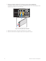
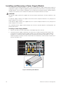
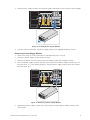
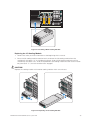
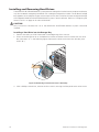
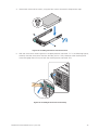
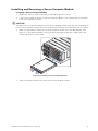
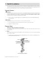
3. Press the retention latch (see letter “A” in the following figure) to release the retention lever.
Rotate the lever out and away from the module bay (see letter “B”) and pull the module
straight out the back of the chassis (see letter “C”).
C
A
B
Figure 7. Removing Management Module
MAXDATA PLATINUM Modular System M1
21