1
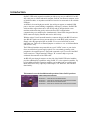
SeaI/O USB Serial User Manual www.sealevel.com PO Box 830 – Liberty, SC 29657 864.843.4343 Table of Contents INTRODUCTION......................................................................................................................... 1 SEAI/O HARDWARE OVERVIEW .......................................................................................... 2 BEFORE YOU GET STARTED................................................................................................. 3 WHAT’S INCLUDED ...................................................................................................................... 3 HARDWARE DESCRIPTION.................................................................................................... 4 SEAI/O RS-232 SERIAL EXPANSION MODULES ........................................................................... 4 SEAI/O RS-232/485 VERSACOM SERIAL EXPANSION MODULES ................................................. 4 POWER OPTIONS ...................................................................................................................... 5 SOFTWARE INSTALLATION .................................................................................................. 7 PHYSICAL INSTALLATION .................................................................................................... 8 TECHNICAL DESCRIPTION.................................................................................................... 9 COMMON FEATURES .................................................................................................................... 9 USB INTERFACE & LED.............................................................................................................. 9 CONNECTOR PIN ASSIGNMENTS (RJ45) – RS-232 ..................................................................... 10 CONNECTOR PIN ASSIGNMENTS (RJ45) – RS-232/485 VERSACOM........................................... 11 INTERFACE SELECTION .............................................................................................................. 11 SEAI/O PASS-THROUGH CONNECTOR ........................................................................................ 12 RS-485 BIASING AND TERMINATION ......................................................................................... 13 POWER ON PIN 5 ........................................................................................................................ 13 OPTIONAL RJ45 TO DB9 RS-232 ADAPTER ............................................................................... 14 PRODUCT SPECIFICATIONS ......................................................................................................... 14 MOUNTING OPTIONS............................................................................................................. 15 ACCESSORIES .......................................................................................................................... 16 APPENDIX A - TROUBLESHOOTING ................................................................................. 18 APPENDIX B - HOW TO GET ASSISTANCE ...................................................................... 19 APPENDIX C – ELECTRICAL INTERFACE ....................................................................... 20 APPENDIX D - ASYNCHRONOUS COMMUNICATIONS ................................................ 21 APPENDIX E – PCB SILK SCREEN ...................................................................................... 22 APPENDIX F – COMPLIANCE NOTICES............................................................................ 23 APPENDIX F – COMPLIANCE NOTICES............................................................................ 23 WARRANTY............................................................................................................................... 24 © Sealevel Systems, Inc. SL9177 Revision 2/2007 SeaI/O USB Serial User Manual Introduction SeaI/O™ USB serial expansion modules provide an easy way to add RS-232 or RS485 serial ports to a Relio industrial computer, SeaPAC touchscreen computer, stack of SeaI/O modules, or anywhere serial devices need to be connected via an available USB port. Available in four and eight port models, the serial ports appear as standard COM ports to the host system enabling compatibility with legacy software. SeaI/O USB serial modules support data rates to 921.6K bps and are designed with a statemachine architecture that greatly reduces the host CPU overhead when communicating over multiple ports simultaneously. Status LEDs integrated into the RJ45 connectors display transmit and receive data activity. With the unique VersaCom multi-interface connector design, both RS-232 and twowire RS-485 signals are always present and active on the RJ45 serial connectors. Simply select the appropriate pin out for RS-232 or two-wire RS-485 on each individual port. There are no internal jumpers or switches to set, so field installation and service is easy. The USB serial modules are powered from your 9-30VDC source or your choice from several Sealevel power supply options. For conveniently powering serial peripherals, the supplied power is fused and connected to pin 5 on each of the RJ45 serial connectors. A high-retention USB type "B" connector helps to prevent accidental disconnection of the USB cable. An RS-485 pass-through connector on the side of the SeaI/O USB serial modules provides additional I/O capabilities using SeaI/O "N" series expansion modules. Up to 246 additional SeaI/O expansion modules can be added and are available with Reed and Form C relays, optically isolated inputs, TTL interfaces, A/D and D/A functionality. This manual covers the installation and operation of these SeaI/O products: USB Serial Expansion Modules SeaI/O-641U – 4-Port RS-232 RJ45 Serial Interface SeaI/O-647U – 4-Port RS-232, RS-485 RJ45 VersaCom Serial Interface SeaI/O-681U – 8-Port RS-232 RJ45 Serial Interface SeaI/O-687U – 8-Port RS-232, RS-485 RJ45 VersaCom Serial Interface © Sealevel Systems, Inc. -1- SeaI/O USB Serial User Manual SeaI/O Hardware Overview SeaI/O Base and Expansion Modules In general, SeaI/O data acquisition modules provide powerful digital, analog, and serial expansion to any host computer. Multiple modules can be daisy chained using convenient pass-through connectors to create a versatile distributed control and monitoring network. For ease of installation, multiple modules can be combined in a local stack or separated up to 4000 feet using the RS-485 expansion interface. The first SeaI/O module connected to the host computer is considered the Base module and connects to the host via one of the following interfaces: E-Series – Ethernet Modbus TCP U-Series – USB Modbus RTU M-Series – RS-485 Modbus RTU S-Series – RS-232 Modbus RTU SeaI/O USB serial expansion modules only connect to the host via USB and will operate as a Base module when connected to digital and analog SeaI/O N-series Expansion Modules. After the Base unit is installed, up to 246 additional SeaI/O N-Series expansion modules can be added to create an I/O network. These expansion modules interface via RS-485 and can be located local to the Base SeaI/O module or remotely located up to 4000 feet away. Local installations (<10’ of cabling) should use the 5” CAT5 RS-485 pass-through cable (Item# CA239) included with each N-series module to connect together two or more modules. Remote expansion modules (>10’ of cabling) should use twisted pair wiring connected via the removable screw terminal connectors. For local installations, power to the expansion modules is supplied from the base module via the pass-through connectors. For remote devices, separate power is required at each expansion module. Refer to the Power Options chapter of this manual for more information on SeaI/O power requirements and power supply sizing. Communicating Via Modbus Commands Sealevel SeaI/O modules are designed to integrate seamlessly into existing Modbus networks. The supported command set will vary depending on the SeaI/O model used. While SeaI/O USB serial expansion modules do not require any Modbus commands to operate, they do pass through all Modbus RTU commands to other connected SeaI/O modules and Modbus compliant devices. The SeaI/O Modules manual (‘SeaIO Modules.pdf’ located in the ‘Manuals’ subfolder on the Sealevel Software CD) covers digital and analog I/O modules and details the supported Modbus command set. The official Modbus specification can be found at www.modbus.org. © Sealevel Systems, Inc. -2- SeaI/O USB Serial User Manual Before You Get Started What’s Included All SeaI/O USB serial expansion modules are shipped with the following items. If any of these items is missing or damaged please contact Sealevel for replacement. SeaI/O USB Serial Expansion Module – (one of the following models) o SeaI/O-641U – 4-Port RS-232 RJ45 Serial Interface o SeaI/O-647U – 4-Port RS-232, RS-485 RJ45 VersaCom Serial Interface o SeaI/O-681U – 8-Port RS-232 RJ45 Serial Interface o SeaI/O-687U – 8-Port RS-232, RS-485 RJ45 VersaCom Serial Interface Item# CA179 – 72” USB ‘A’ to ‘B’ Device Cable Item# LB116 – RS-232 RJ45 Serial Loopback Item# LB115 – RS-485 RJ45 Serial Loopback (only VersaCom models) Sealevel Software CD – includes SeaMAX software and PDF manuals Each SeaI/O module is shipped with 4 adhesive rubber feet that can be attached to the bottom of the enclosure to enhance the stability in table mount applications. Power Supplies SeaI/O USB serial expansion modules are powered from your 9-30VDC source or from a variety of Sealevel power supply options. Refer to the Power Options chapter of this manual for power supply sizing considerations when powering multiple SeaI/O modules. Loopback Adapters All SeaI/O USB serial expansion modules include an RJ45 RS-232 serial loopback adapter (Item# LB116) that is useful for testing the data signals on RS-232 ports. SeaI/O USB serial models with RS-485 VersaCom ports also include an RJ45 RS485 loopback cable (Item# LB115) that is useful for testing the data signals between a pair of RS-485 ports. WinSSD is a full featured asynchronous serial diagnostic utility for Windows that allows you to modify default parameters, perform loopback tests, toggle modem control signals, and transmit test pattern messages. WinSSD can be found on the Sealevel Software CD in the ‘Software/Utilities/WinSSD’ subfolder. © Sealevel Systems, Inc. -3- SeaI/O USB Serial User Manual Hardware Description SeaI/O RS-232 Serial Expansion Modules Models SeaI/O-641U SeaI/O-681U USB to 4-Port RS-232 RJ45 Serial Interface USB to 8-Port RS-232 RJ45 Serial Interface Features Utilizes high speed UARTs with 128-byte Tx FIFOs and 384-byte Rx FIFOs Provides four or eight RJ45 RS-232 serial ports with Tx/Rx status LEDs Integrates transmit and receive LED indicators on each port Input power via terminal block or barrel connector USB 1.1 compliant, USB 2.0 compatible High-retention USB type “B” connector prevents accidental disconnection of USB cable Power Requirements 9-30VDC @ 1.5W SeaI/O RS-232/485 VersaCom Serial Expansion Modules Models SeaI/O-647U SeaI/O-687U USB to 4-Port RS-232/485 RJ45 VersaCom Serial Interface USB to 8-Port RS-232/485 RJ45 VersaCom Serial Interface Features Utilizes high speed UARTs with 128-byte Tx FIFOs and 384-byte Rx FIFOs Provides four or eight RJ45 RS-232 serial ports with Tx/Rx status LEDs Integrates transmit and receive LED indicators on each port VersaCom design allows RS-232 or two-wire RS-485 selection via cabling on each individual port Input power via terminal block or barrel connector USB 1.1 compliant, USB 2.0 compatible High-retention USB type “B” connector prevents accidental disconnection of USB cable Power Requirements 9-30VDC @ 2.5W © Sealevel Systems, Inc. -4- SeaI/O USB Serial User Manual Power Options All SeaI/O modules are powered from a 9-30VDC source using either the DC jack or screw terminals on the side of the unit. Sealevel offers several power supply choices to make connection easy (see Accessories chapter at the end of this manual). If the SeaI/O USB serial expansion module will be used alone, the recommended “single-unit” power supply (Item# TR112) rated at 24VDC @ 250mA is a perfect fit. Skip ahead to the Software Installation chapter of this manual. One of the primary features of SeaI/O modules is their ability to be powered from a single input source, which is then shared with other SeaI/O expansion modules via pass-through connectors or screw terminals located on the left side of the modules. If you’re connecting multiple SeaI/O modules together, refer to the rest of this chapter for power supply sizing considerations. SeaI/O Expansion Power Connection Each SeaI/O product, including the expansion modules, contains an onboard switching regulator power supply rated for 9-30VDC. For local installations (less than 10’ apart), expansion module power is usually supplied from the Base module via the pass-through connectors. The number of expansion modules that can be driven from the Base module depends on the power source and number/type of expansion modules. Refer to the chart below for power requirements. For expansion modules mounted remotely (greater than 10’ apart), separate power is required at each expansion module. SeaI/O Expansion Power Requirements The following table shows the maximum power requirements for each SeaI/O digital and analog expansion module. Model Number SeaI/O-410N Max Power 1.4W SeaI/O-420N 2.0W SeaI/O-430N 0.4W SeaI/O-440N 2.5W SeaI/O-450N 3.8W SeaI/O-470N 1.5W SeaI/O-520N 3.5W © Sealevel Systems, Inc. -5- SeaI/O USB Serial User Manual TTL Expansion Power Requirements The SeaI/O-462N and SeaI/O-463N use 74ABT245 octal bi-directional transceivers to provide TTL input/output capabilities and can sink 64mA and source 32mA. Each bit is pulled to +5V through a 10K ohm pull-up resistor to insure each bit is at a known state when not driven. The supply current and maximum output power for the TTL expansion modules is shown in the table below. Model Number SeaI/O-462N Max Power 0.5W SeaI/O-463N 0.5W Output Power +5VDC @ 1A (5W) Maximum Sample Power Calculation A typical application for SeaI/O products would use one Base module and several Nseries expansion modules in a local “stack” configuration. In this arrangement, with power applied to the Base module through either the DC jack or screw terminal connector and passed-through to the expansion modules, attention should be given to ensure the input power to all connected modules is adequate. Example: Base Module: Expansion 1: Expansion 2: SeaI/O-641U SeaI/O-410N SeaI/O-440N Power (W) 1.5 1.4 2.5 5.4W Power Required In this application, the Sealevel Item# TR112 “wall wart” power supply is a good choice since it is low-cost and supplies 24VDC @ 250mA (6W). NOTE: © Sealevel Systems, Inc. A complete listing of recommended power supplies is provided in the Accessories chapter at the end of this manual. -6- SeaI/O USB Serial User Manual Software Installation SeaMAX Software Installation Proceed with installing the SeaMAX Software Suite using the software CD that was included with your SeaI/O serial expansion module. Software drivers are also available on the product webpage on the Sealevel website at www.sealevel.com. Windows 98/ME/2000/XP Installation Do not connect the SeaI/O module to the host until the software is installed. 1. Start Windows. 2. Insert the Sealevel Software CD in to your CD drive. 3. If ‘Auto-Start’ is enabled the installation window will automatically appear. Otherwise, navigate to the root directory of your CD drive and double-click the ‘autorun.exe’ application to launch the installation window. 4. Select ‘Install Software’. 5. Select the Part Number for your device from the listing. 6. The setup file will automatically detect the operating environment and install the proper components. Follow the information presented on the installation screens that follow. 7. A screen may appear with the declaration: “The publisher cannot be determined due to the problems below: Authenticode signature not found.” Please select the ‘Yes’ button and proceed with the installation. This declaration simply means that the Operating System is not aware of the driver being loaded. It will not cause any harm to your system. 8. During setup, you may specify installation directories and other preferred configurations. This program also adds entries to the system registry that are necessary for specifying the operating parameters for each driver. An uninstall option is included to remove the driver and all registry/INI file entries from your system. 9. Proceed with the physical installation of your SeaI/O USB serial expansion module. NOTE: Windows NT is not USB aware and thus cannot support this device. © Sealevel Systems, Inc. -7- SeaI/O USB Serial User Manual Physical Installation SeaI/O USB serial expansion modules can be connected to any spare USB port. Do not connect the SeaI/O module to the host until the software is installed. 1. Connect the SeaI/O USB serial expansion module to your 9-30VDC source or optional Sealevel power supply. Refer to the Power Options chapter of this manual for power requirements. 2. Connect the SeaI/O USB serial expansion module to a USB port with the supplied USB device cable. 3. The software drivers installed during setup will automatically recognize and configure the device. 4. You should see one or more “New Hardware Found” windows, indicating the actual device being created. 5. NOTE: The installation will repeat twice for each COM port (a total of 8 times on 4-port models, and 16 times on 8-port models). This is a limitation in the way Windows installs external serial devices. 6. Next, view your system’s Device Manager. 7. You should have new COM: ports in the Ports (COM & LPT) Device Class indicating the installation was successful. 8. You can access your new COM: port by using the assigned COM: identifier. This assignment will vary from system to system. 9. To verify operation use Sealevel Systems supplied WinSSD diagnostic utility. WinSSD can be found on the Sealevel Software CD in the ‘Software/Utilities/WinSSD’ subfolder. Your SeaI/O serial expansion module is now ready for use. © Sealevel Systems, Inc. -8- SeaI/O USB Serial User Manual Technical Description The SeaI/O USB serial expansion modules utilize USB UARTs. These chips feature programmable baud rate, data format, 128 byte Dual Port TX Buffer, and 384 byte Dual Port RX Buffer. The transceivers support data rates up to 921.6K bps. and integrated status LEDs on each RJ45 serial port display transmit and receive data activity. Common Features All SeaI/O USB serial expansion modules include the same connectors on the left side – RJ45 RS-485 pass-through connector, 1.3mm 9-30VDC barrel connector, and a 6-position removable screw terminal: USB Interface & LED A high-retention USB Type “B” connector helps to prevent accidental disconnection of the USB cable. A green status LED next to the USB connector (labeled ‘PWR’) lights to indicate the module is properly connected to an input power source. © Sealevel Systems, Inc. -9- SeaI/O USB Serial User Manual Connector Pin Assignments (RJ45) – RS-232 The SeaI/O 641U and 681U utilize the RS-232 connector pin out. Integrated status LEDs on each RJ45 serial port display transmit and receive data activity. NC RTS TX GND PWR RX CTS NC Name No Connect Request To Send Transmit Data Ground Power Output Receive Data Clear To Send No Connect NOTE: © Sealevel Systems, Inc. Pin # 1 2 3 4 5 6 7 8 Mode Output Output Input Input DCD, DSR, and RI are inputs that are not brought out on the RJ45 connector. DSR and DCD are biased active and RI is biased inactive. - 10 - SeaI/O USB Serial User Manual Connector Pin Assignments (RJ45) – RS-232/485 VersaCom The SeaI/O 647U and 687U utilize the RS-232/485 VersaCom connector pin out. Integrated status LEDs on each RJ45 serial port display transmit and receive data activity. D+ RTS TX GND PWR RX CTS D- Name RS-485 Data + Request To Send Transmit Data Ground Power Output Receive Data Clear To Send RS-485 Data – NOTE: Pin # 1 2 3 4 5 6 7 8 Mode Output Output Input Input DCD, DSR, and RI are inputs that are not brought out on the RJ45 connector. DSR and DCD are biased active and RI is biased inactive. Interface Selection With the unique VersaCom multi-interface connector design, both RS-232 and twowire RS-485 signals are always present and active on the RJ45 connectors. Simply select the appropriate pin out for RS-232 or two-wire RS-485 on each individual port. The unused interface on each connector should be left unconnected. All inputs have appropriate biasing to keep them in an inactive state. If the unused interface pins are connected to a cable, the outputs will attempt to drive the lines while the inputs will attempt to interpret any voltage on the line as data, which can limit cable length and may result in communication failures. © Sealevel Systems, Inc. - 11 - SeaI/O USB Serial User Manual SeaI/O Pass-Through Connector All SeaI/O USB serial expansion modules include an RS-485 pass-through connector on the left side of the unit that is internally connected to the same pins on the removable screw terminals. This offers two convenient options for adding SeaI/O digital and analog expansion modules. The image on the following page shows the pass-through connector and removable screw terminals. For connecting several SeaI/O modules together in a “stack”, all N-series expansion modules ship with an expansion and strap kit (item# KT122) that includes four metal straps, four #4-40 screws, and a 5” RJ45 RS-485 interconnect cable (item# CA239). The metal straps allow you to securely connect multiple SeaI/O modules together. The interconnect cable can be used to connect SeaI/O modules together via the RJ45 pass-through connectors, providing an easy method to cascade RS-485 signals and power from one module to the next. For expansion modules that are less than ten feet from a base unit, a standard RJ45 CAT5 patch cable may be used. For SeaI/O modules greater than ten feet apart, use twisted-pair cable connecting the data lines to the screw terminals instead. If RJ45 connectors are preferred, be sure to connect only the data lines (pins 4 & 5). NOTE: © Sealevel Systems, Inc. Modules greater than ten feet apart must have separate power supplies. Refer to the Power Options chapter of this manual for recommendations. - 12 - SeaI/O USB Serial User Manual RS-485 Biasing and Termination All RJ45 RS-485 inputs have the appropriate biasing to keep them in an inactive state when not connected to a cable. When cabling for RS-232 signals, be sure to leave the RS-485 pins unconnected. If the unused interface pins are connected to a cable, the outputs will attempt to drive the lines while the inputs will attempt to interpret any voltage on the line as data, which can limit cable length and may result in communication failures. 120Ω termination resistor always present between Data+ and Data510Ω Biasing pull-up resistors on Data+ 510Ω Biasing pull-down resistors on Data- NOTE: RS-485 networks should have termination enabled on each end of the network. SeaI/O USB serial modules have appropriate biasing and termination enabled. Pull-up and pull-down resistors should also be enabled on the last device on the RS-485 network. Power on Pin 5 For conveniently powering serial peripherals, the input power is fused and connected to pin 5 on each of the RJ45 serial connectors. Each serial port utilizes an autoresetting fuse rated at 500mA. All powered serial peripherals must have the same input voltage and be within the 9-30VDC range. The input current must be rated higher than the combined current requirement of the SeaI/O USB serial expansion module and any devices powered by the serial ports and the RS-485 pass-through connector. © Sealevel Systems, Inc. - 13 - SeaI/O USB Serial User Manual Optional RJ45 to DB9 RS-232 Adapter Preconfigured for use with Sealevel USB RJ45-enabled serial adapters, the RJ45 to DB9 modular adapter (item# RJ9P-232) converts the RJ45 RS-232 pin out to a DB9 male RS-232 serial port. Standard CAT5 patch cables can be used to extend the serial port up to 50 feet away from the RJ45 port. The pin out for the RJ9P-232 is shown below. Product Specifications Temperature Range Operating: Storage: -0°C – 70°C -50°C – 105°C Dimensions Length 7.5” 19.05 cm Width 5.1” 12.95 cm Height 1.3” 3.30 cm Manufacturing All Sealevel Systems Printed Circuit boards are built to UL 94V0 rating and are 100% electrically tested. These printed circuit boards are solder mask over bare copper or solder mask over tin nickel. © Sealevel Systems, Inc. - 14 - SeaI/O USB Serial User Manual Mounting Options SeaI/O Mounting Kit Expanding your I/O count is as simple as adding N-Series expansion units to the Base SeaI/O module (or other N-series modules). Each NSeries module includes an expansion and strap kit (Item# KT122), which includes a 5” CAT5 interconnect cable, four metal straps, and four #440 metal screws. The image shows a SeaI/O stack configuration using the expansion kit. DIN Rail Mounting All SeaI/O modules are available with a factoryinstalled DIN-rail mounting clip. Alternatively DIN-rail mounting clips can be ordered as a field upgrade kit (Item# DR104). The bracket with clip is easily attached using two included #4-40 Phillips head machine screws. Table/Wall Mounting The flush mount bracket kit (Item# KT123) is extremely versatile and can be used to mount SeaI/O modules from the top, bottom, or back edge. Individual modules or a stack of SeaI/O modules can be mounted flat to a tabletop, underneath a counter, or inside an enclosure. The kit can be used to mount SeaI/O modules flat to a wall, or along the back edge, similar to DIN-rail mounting options. Universal Mounting Bracket The universal mounting bracket (Item# KT125) can be used as a “backpack” to mount power supplies and other devices to SeaI/O modules. The bracket has holes for both 75mm and 100mm VESA mounting options. The universal arrangement of slots and holes accept bolt sizes to M4 and can be used for virtually any mounting configuration. © Sealevel Systems, Inc. - 15 - SeaI/O USB Serial User Manual Accessories Depending upon your application, you are likely to find one or more of the following items useful for interfacing SeaI/O serial expansion modules. All items can be purchased from our website (http://www.sealevel.com) or by calling 864-843-4343. Power Supplies US Options TR112 – 120VAC to 24VDC 250mA “Wall Wart” Power Supply with 1.3mm Plug (for single SeaI/O module) TR109 – 120VAC to 24VDC 500mA “Wall Wart” Power Supply with 1.3mm Plug (for multiple SeaI/O modules) TR108-US – 100-250VAC to 24VDC 36W 1.5A “Desktop” Power Supply with 1.3mm Plug, includes (CA248) Nema 5-15P 6’ US Power Cord PS101 – 100-240VAC to 24VDC 7.5W 300mA DIN Rail Mount Power Supply (connects via screw terminals, no wire included) PS103 – 100-240VAC to 24VDC 50W 2.1A DIN Rail Mount Power Supply (connects via screw terminals, no wire included) International Options TR108-AU - 100-250VAC to 24VDC 36W 1.5A “Desktop” Power Supply with 1.3mm Plug, includes (CA187) “AS 3112” 6’ Australian Power Cord TR108-EC - 100-250VAC to 24VDC 36W 1.5A “Desktop” Power Supply with 1.3mm Plug, includes (CA188) “Schuko” 6’ Continental European Power Cord TR108-UK - 100-250VAC to 24VDC 36W 1.5A “Desktop” Power Supply with 1.3mm Plug, includes (CA189) “BS 1363” 6’ UK Power Cord TR108 – 100-250VAC to 24VDC 36W 1.5A “Desktop” Power Supply with 1.3mm Plug, requires IEC country-specific Power Cord © Sealevel Systems, Inc. - 16 - SeaI/O USB Serial User Manual Mounting Options KT122 – Expansion & Strap Kit. Includes 5” RS-485 Interconnect Cable (item# CA239), four metal straps, and four #4-40 metal screws, for connecting two SeaI/O modules together in a “stack” KT123 – Flush Mount Bracket Kit. Includes two metal brackets and four #4-40 metal screws, for mounting SeaI/O modules or stacks in a variety of positions and locations KT125 – Universal Mounting Bracket. Includes metal mounting bracket and four #4-40 metal screws, for mounting devices to SeaI/O modules or mounting SeaI/O modules to VESA mounts and other devices. DR104 – DIN Rail Mounting Assembly. Connects to the back edge of SeaI/O modules to facilitate an easy DIN rail mounting option and a cleaner installation RK1U – 1U 19” Rack Tray RK2U – 2U 19” Rack Tray RK-CLAMP – Securely holds SeaI/O modules to rack trays Cabling Options CA239 – 5” CAT5 RS-485 Interconnect Cable, used to connect SeaI/O modules together in a stack (included in 4xxN SeaI/O expansion modules) CA246 – 7’ Blue Ethernet Patch Cable. Can be used to connect SeaI/O Ethernet modules to a hub (included with 4xxE SeaI/O Ethernet modules). Can be used to connect SeaI/O RS-232 modules to both Sealevel and standard RS-232 serial ports (included with 4xxS SeaI/O RS-232 modules as part of p/n: KT119). Optionally, it can be used as an RS-485 interconnect cable to cascade additional SeaI/O modules via the RS-485 In/Out ports on the side of SeaI/O modules CA247 – 10’ Blue Ethernet Patch Cable. Can be used to connect SeaI/O Ethernet modules to a hub, or can be used as an RS-485 interconnect cable to cascade SeaI/O modules via the RS-485 In/Out ports CA179 – USB 6’ A to B Cable (included with SeaI/O USB modules) © Sealevel Systems, Inc. - 17 - SeaI/O USB Serial User Manual Appendix A - Troubleshooting Sealevel includes diagnostic utilities with Sealevel products to assist with troubleshooting procedures. Using the diagnostic software and following these simple steps can eliminate most common problems without the need to call Technical Support. 1. Read this manual thoroughly before attempting to install the device in your system. 2. Uninstall any previous versions of SeaMAX software before installing any new versions. 3. Install SeaMAX software first. Installing the software places the necessary files in the proper locations on your system. After installing the software, proceed with adding the hardware. 4. If your module isn’t working at all, first check to make sure that USB support is enabled in the System BIOS and it is functioning properly. This can be done by using Device Manager and expanding ‘Ports (COM &LPT)’. 5. Confirm that all screw terminal connections are correct and secure and that the correct cables and adapters are being used. Verify that cables are using the proper pin out on both ends of the connection. 6. When SeaI/O serial expansion modules are configured properly, Sealevel’s WinSSD utility and a loopback plug can be used to verify serial communications. You can make a simple Loopback in the field by connecting the TX and RX pins. Details on loopback plugs are included within WinSSD. WinSSD can be found on the Sealevel Software CD in the ‘Software/Utilities/WinSSD’ subfolder. 7. When testing the serial connections in loopback mode using WinSSD, you should see both the TD and RD echoed as data on the screen. The loopback test first transmits a HEX pattern, 55AA, and then an ASCII string of data. If this test passes, then the serial expansion module is ready for use in your application. 8. Always use Sealevel diagnostic software utilities when troubleshooting a problem. This will eliminate any software issues from the equation. If these steps do not solve your problem, please call Sealevel Systems’ Technical Support, (864) 843-4343. Our technical support is free and available from 8:00 AM to 5:00 PM Eastern Time, Monday through Friday. For email support, contact [email protected]. © Sealevel Systems, Inc. - 18 - SeaI/O USB Serial User Manual Appendix B - How To Get Assistance When calling for technical assistance, please have your user manual and current device settings ready. If possible, please have the device installed and ready to run diagnostics. Sealevel Systems maintains a website on the Internet. Our homepage address is http://www.sealevel.com. The latest software updates and newest manuals are available via our FTP site that can be accessed from our home page. Manuals and software can also be downloaded from the product page for your device. Sealevel Systems provides an FAQ section on our website. Please refer to this to answer many common questions. This section can be found at http://www.sealevel.com/faq.asp Technical support is available Monday to Friday from 8:00 a.m. to 5:00 p.m. eastern time. You can contact Technical Support via: Phone: (864) 843-4343 Email: [email protected] RETURN AUTHORIZATION MUST BE OBTAINED FROM SEALEVEL SYSTEMS BEFORE RETURNED MERCHANDISE WILL BE ACCEPTED. AUTHORIZATION CAN BE OBTAINED BY CALLING SEALEVEL SYSTEMS AND REQUESTING A RETURN MERCHANDISE AUTHORIZATION (RMA) NUMBER. © Sealevel Systems, Inc. - 19 - SeaI/O USB Serial User Manual Appendix C – Electrical Interface RS-232 Quite possibly the most widely used communication standard is RS-232. This implementation has been defined and revised several times and is often referred to as RS-232 or EIA/TIA-232. The IBM PC computer defined the RS-232 port on a 9 pin D sub connector and subsequently the EIA/TIA approved this implementation as the EIA/TIA-574 standard. This standard is defined as the 9-Position Non-Synchronous Interface between Data Terminal Equipment and Data Circuit-Terminating Equipment Employing Serial Binary Data Interchange. Both implementations are in wide spread use and will be referred to as RS-232 in this document. RS-232 is capable of operating at data rates up to 20 Kbps at distances less than 50 ft. The absolute maximum data rate may vary due to line conditions and cable lengths. RS-232 is a single ended or unbalanced interface, meaning that a single electrical signal is compared to a common signal (ground) to determine binary logic states. The RS-232 and the EIA/TIA-574 specification define two types of interface circuits, Data Terminal Equipment (DTE) and Data Circuit-Terminating Equipment (DCE). The SeaLINK+4.VC is a DTE device. RS-485 RS-485 is backwardly compatible with RS-422; however, it is optimized for party-line or multi-drop applications. The output of the RS-422/485 driver is capable of being Active (enabled) or Tri-State (disabled). This capability allows multiple ports to be connected in a multi-drop bus and selectively polled. RS-485 allows cable lengths up to 4000 feet and data rates up to 10 Megabits per second. The signal levels for RS-485 are the same as those defined by RS-422. RS-485 has electrical characteristics that allow for 32 drivers and 32 receivers to be connected to one line. This interface is ideal for multi-drop or network environments. RS-485 tri-state driver (not dual-state) will allow the electrical presence of the driver to be removed from the line. Only one driver may be active at a time and the other driver(s) must be tri-stated. RS-485 can be cabled in two ways, two wire and four wire mode. Two wire mode does not allow for full duplex communication, and requires that data be transferred in only one direction at a time. For half-duplex operation, the two transmit pins should be connected to the two receive pins (Tx+ to Rx+ and Tx- to Rx-). Four wire mode allows full duplex data transfers. RS-485 does not define a connector pin-out or a set of modem control signals. RS-485 does not define a physical connector. © Sealevel Systems, Inc. - 20 - SeaI/O USB Serial User Manual Appendix D - Asynchronous Communications Serial data communications implies that individual bits of a character are transmitted consecutively to a receiver that assembles the bits back into a character. Data rate, error checking, handshaking, and character framing (start/stop bits) are pre-defined and must correspond at both the transmitting and receiving ends. Asynchronous communications is the standard means of serial data communication for PC compatibles and PS/2 computers. The original PC was equipped with a communication or COM: port that was designed around an 8250 Universal Asynchronous Receiver Transmitter (UART). This device allows asynchronous serial data to be transferred through a simple and straightforward programming interface. A starting bit followed by a pre-defined number of data bits (5, 6, 7, or 8) defines character boundaries for asynchronous communications. The end of the character is defined by the transmission of a pre-defined number of stop bits (usually 1, 1.5 or 2). An extra bit used for error detection is often appended before the stop bits. Idle state of line 5 to 8 Data Bits Odd, Even or Unused Remain Idle or next start bit 1 P BIT STOP 0 1 1.5 2 This special bit is called the parity bit. Parity is a simple method of determining if a data bit has been lost or corrupted during transmission. There are several methods for implementing a parity check to guard against data corruption. Common methods are called (E)ven Parity or (O)dd Parity. Sometimes parity is not used to detect errors on the data stream. This is refereed to as (N)o parity. Because each bit in asynchronous communications is sent consecutively, it is easy to generalize asynchronous communications by stating that each character is wrapped (framed) by pre-defined bits to mark the beginning and end of the serial transmission of the character. The data rate and communication parameters for asynchronous communications have to be the same at both the transmitting and receiving ends. The communication parameters are baud rate, parity, number of data bits per character, and stop bits (i.e. 9600, N, 8, 1). © Sealevel Systems, Inc. - 21 - SeaI/O USB Serial User Manual Appendix E – PCB Silk Screen © Sealevel Systems, Inc. - 22 - SeaI/O USB Serial User Manual Appendix F – Compliance Notices Federal Communications Commission Statement FCC - This equipment has been tested and found to comply with the limits for Class A digital device, pursuant to Part 15 of the FCC Rules. These limits are designed to provide reasonable protection against harmful interference when the equipment is operated in a commercial environment. This equipment generates, uses, and can radiate radio frequency energy and, if not installed and used in accordance with the instruction manual, may cause harmful interference to radio communications. Operation of this equipment in a residential area is likely to cause harmful interference in such case the user will be required to correct the interference at the user’s expense. EMC Directive Statement Products bearing the CE Label fulfill the requirements of the EMC directive (89/336/EEC) and of the low-voltage directive (73/23/EEC) issued by the European Commission. To obey these directives, the following European standards must be met: EN55022 Class A - “Limits and methods of measurement of radio interference characteristics of information technology equipment” EN55024 – “Information technology equipment Immunity characteristics Limits and methods of measurement”. EN60950 (IEC950) - “Safety of information technology equipment, including electrical business equipment” Warning This is a Class A Product. In a domestic environment, this product may cause radio interference in which case the user may be required to take adequate measures to prevent or correct the interference. Always use cabling provided with this product if possible. If no cable is provided or if an alternate cable is required, use high quality shielded cabling to maintain compliance with FCC/EMC directives. © Sealevel Systems, Inc. - 23 - SeaI/O USB Serial User Manual Warranty Sealevel's commitment to providing the best I/O solutions is reflected in the Lifetime Warranty that is standard on all Sealevel manufactured products. We are able to offer this warranty due to our control of manufacturing quality and the historically high reliability of our products in the field. Sealevel products are designed and manufactured at its Liberty, South Carolina facility, allowing direct control over product development, production, burn-in and testing. Sealevel Systems, Inc. (hereafter "Sealevel") warrants that the Product shall conform to and perform in accordance with published technical specifications and shall be free of defects in materials and workmanship for life. In the event of failure, Sealevel will repair or replace the product at Sealevel's sole discretion. Failures resulting from misapplication or misuse of the Product, failure to adhere to any specifications or instructions, or failure resulting from neglect or abuse are not covered under this warranty. Warranty service is obtained by delivering the Product to Sealevel and providing proof of purchase. NOTE: Return authorization must be obtained from Sealevel Systems before returned merchandise will be accepted. Authorization is obtained by calling Sealevel Systems and requesting a Return Merchandise Authorization (RMA) number. The Customer agrees to insure the Product or assume the risk of loss or damage in transit, to prepay shipping charges to Sealevel, and to use the original shipping container or equivalent. Warranty is valid only for original purchaser and is not transferable. Sealevel Systems assumes no liability for any damages, lost profits, lost savings or any other incidental or consequential damage resulting from the use, misuse of, or inability to use this product. Sealevel Systems will not be liable for any claim made by any other related party. This warranty applies to Sealevel manufactured Product. Product purchased through Sealevel but manufactured by a third party will retain the original manufacturer's warranty. Sealevel Systems, Incorporated 2779 Greenville Highway P.O. Box 830 Liberty, SC 29657 USA (864) 843-4343 FAX: (864) 843-3067 www.sealevel.com email: [email protected] Technical Support is available Monday - Friday from 8 a.m. to 5 p.m. Eastern time. Trademarks Sealevel Systems, Incorporated acknowledges that all trademarks referenced in this manual are the service mark, trademark, or registered trademark of the respective company. © Sealevel Systems, Inc. - 24 - SeaI/O USB Serial User Manual