1
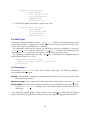
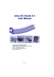
IRD User Manual
telos Systementwicklung GmbH
Schlueterstrasse 16, 20146 Hamburg /Germany
Phone: +49 (0)40 450 173 61
Mail: [email protected]
Web: www.telos.info
July 17, 2013
Contents
1 Introduction
4
2 XML Header
4
3 IRD Structure
4
4 Header
4.1 Introduction . . . . . . . . . . . .
4.2 I2C Addresses . . . . . . . . . . .
4.2.1 Single Address . . . . . .
4.2.2 Address Range . . . . . .
4.3 Manufacturer . . . . . . . . . . .
4.4 Name . . . . . . . . . . . . . . . .
4.5 Description . . . . . . . . . . . . .
4.6 Sub Address . . . . . . . . . . . .
4.7 Auto Increment . . . . . . . . . .
4.8 Bus Type . . . . . . . . . . . . . .
4.9 Unique Device Identifier (UDID)
.
.
.
.
.
.
.
.
.
.
.
.
.
.
.
.
.
.
.
.
.
.
.
.
.
.
.
.
.
.
.
.
.
.
.
.
.
.
.
.
.
.
.
.
.
.
.
.
.
.
.
.
.
.
.
.
.
.
.
.
.
.
.
.
.
.
.
.
.
.
.
.
.
.
.
.
.
.
.
.
.
.
.
.
.
.
.
.
.
.
.
.
.
.
.
.
.
.
.
.
.
.
.
.
.
.
.
.
.
.
.
.
.
.
.
.
.
.
.
.
.
.
.
.
.
.
.
.
.
.
.
.
.
.
.
.
.
.
.
.
.
.
.
.
.
.
.
.
.
.
.
.
.
.
.
.
.
.
.
.
.
.
.
.
.
.
.
.
.
.
.
.
.
.
.
.
.
.
.
.
.
.
.
.
.
.
.
.
.
.
.
.
.
.
.
.
.
.
.
.
.
.
.
.
.
.
.
.
.
.
.
.
.
.
.
.
.
.
.
.
.
.
.
.
.
.
.
.
.
.
.
5
5
6
6
6
6
7
7
7
8
8
8
5 Register
5.1 Introduction . . . . . . . . . . . . . . . . . . .
5.2 Identifier . . . . . . . . . . . . . . . . . . . . .
5.3 Sub Addresses . . . . . . . . . . . . . . . . . .
5.4 Format . . . . . . . . . . . . . . . . . . . . . .
5.4.1 Quick Command . . . . . . . . . . . .
5.4.2 Send/Receive Byte . . . . . . . . . . .
5.4.3 Empty . . . . . . . . . . . . . . . . . .
5.4.4 Write/Read Byte/Word/DWord . . .
5.4.5 Process Call . . . . . . . . . . . . . . .
5.4.6 Block Write/Read . . . . . . . . . . . .
5.4.7 Block Write - Block Read Process Call
5.5 Name . . . . . . . . . . . . . . . . . . . . . . .
5.6 Power-On Reset . . . . . . . . . . . . . . . . .
.
.
.
.
.
.
.
.
.
.
.
.
.
.
.
.
.
.
.
.
.
.
.
.
.
.
.
.
.
.
.
.
.
.
.
.
.
.
.
.
.
.
.
.
.
.
.
.
.
.
.
.
.
.
.
.
.
.
.
.
.
.
.
.
.
.
.
.
.
.
.
.
.
.
.
.
.
.
.
.
.
.
.
.
.
.
.
.
.
.
.
.
.
.
.
.
.
.
.
.
.
.
.
.
.
.
.
.
.
.
.
.
.
.
.
.
.
.
.
.
.
.
.
.
.
.
.
.
.
.
.
.
.
.
.
.
.
.
.
.
.
.
.
.
.
.
.
.
.
.
.
.
.
.
.
.
.
.
.
.
.
.
.
.
.
.
.
.
.
.
.
.
.
.
.
.
.
.
.
.
.
.
.
.
.
.
.
.
.
.
.
.
.
.
.
.
.
.
.
.
.
.
.
.
.
.
.
.
.
.
.
.
.
.
.
.
.
.
.
.
.
.
.
.
.
.
.
.
.
.
.
.
.
.
.
.
.
.
.
.
.
.
.
.
.
.
.
.
.
.
.
.
.
.
.
.
.
.
.
.
9
9
9
9
9
9
10
10
10
10
11
11
11
11
6 Types
6.1 Introduction . . . . .
6.2 Integer Types . . . .
6.2.1 type int . . .
6.2.2 type int value
6.2.3 Examples . .
6.3 ASCII Types . . . . .
6.4 String Types . . . . .
.
.
.
.
.
.
.
.
.
.
.
.
.
.
.
.
.
.
.
.
.
.
.
.
.
.
.
.
.
.
.
.
.
.
.
.
.
.
.
.
.
.
.
.
.
.
.
.
.
.
.
.
.
.
.
.
.
.
.
.
.
.
.
.
.
.
.
.
.
.
.
.
.
.
.
.
.
.
.
.
.
.
.
.
.
.
.
.
.
.
.
.
.
.
.
.
.
.
.
.
.
.
.
.
.
.
.
.
.
.
.
.
.
.
.
.
.
.
.
.
.
.
.
.
.
.
.
.
.
.
.
.
.
.
.
.
.
.
.
.
11
11
12
12
13
13
14
14
.
.
.
.
.
.
.
.
.
.
.
.
.
.
.
.
.
.
.
.
.
.
.
.
.
.
.
.
.
.
.
.
.
.
.
.
.
.
.
.
.
.
.
.
.
.
.
.
.
.
.
.
.
.
.
.
.
.
.
.
.
.
.
.
.
.
.
.
.
.
.
.
.
.
.
.
.
.
.
.
.
.
.
.
.
.
.
.
.
.
.
.
.
.
.
.
.
.
.
.
.
.
.
2
.
.
.
.
.
.
.
.
.
.
.
.
.
.
.
.
.
.
.
.
.
.
.
.
.
.
.
.
.
.
.
.
.
.
.
.
.
.
.
.
.
.
.
.
.
.
.
.
.
.
.
.
.
.
.
.
.
.
.
.
.
7 Values
7.1 value . .
7.2 source . .
7.3 type . . .
7.4 Examples
.
.
.
.
.
.
.
.
.
.
.
.
.
.
.
.
.
.
.
.
.
.
.
.
.
.
.
.
.
.
.
.
.
.
.
.
.
.
.
.
.
.
.
.
.
.
.
.
.
.
.
.
.
.
.
.
.
.
.
.
.
.
.
.
.
.
.
.
8 Example
.
.
.
.
.
.
.
.
.
.
.
.
.
.
.
.
.
.
.
.
.
.
.
.
.
.
.
.
.
.
.
.
.
.
.
.
.
.
.
.
.
.
.
.
.
.
.
.
.
.
.
.
.
.
.
.
.
.
.
.
.
.
.
.
.
.
.
.
.
.
.
.
.
.
.
.
.
.
.
.
.
.
.
.
.
.
.
.
.
.
.
.
.
.
.
.
15
15
15
16
16
18
3
1 Introduction
A bus tracer is able to display low level information like register addresses and read or written data only. Thus, a user must check the IC specification for advanced information if the
meaning of the register data is not evident.
To handle this constraint, telos invented a register description language for I2C and SMBus
ICs. This language helps to transform manufacturer data sheets and design specifications into
a XML-based file. This allows a tracer application software like telos I2C Studio to display
high level information about IC registers and their mode of operation.
No knowledge of programming languages is needed to write IRD files. The following
article gives a brief introduction into the creation of IRD files.
For unapproved users telos provides an IRD File Creation Service for any desired IC. Please
feel free to ask for further information.
2 XML Header
Each IRD file starts with the following XML header:
<?xml version="1.0" encoding="utf-8"?>
<device xsi:schemaLocation="http://www.telos.de/namespace/ird ird.xsd"
xmlns:xsi="http://www.w3.org/2001/XMLSchema-instance"
xmlns="http://www.telos.de/namespace/ird">
This header defines the used character encoding and file format.
UTF-8 is the 8 bit Unicode Transformation Format for character encoding. In contrast to the
ASCII encoding UTF-8 supports all characters of the Unicode standard. The first part of the
UTF-8 code [0,..,127] is equal to ASCII. For a full UTF-8 support it is necessary to use an editor
which supports this encoding.
IRD files have to be stored with the extension ”.xml”.
3 IRD Structure
All elements of an IRD file, except for the XML header mentioned above, must be placed
between the following two identifiers:
<device xsi:schemaLocation="http://www.telos.de/namespace/ird ird.xsd"
xmlns:xsi="http://www.w3.org/2001/XMLSchema-instance"
xmlns="http://www.telos.de/namespace/ird">
<!-<!-- Header
<!--
-->
-->
-->
(...)
<!--
-->
4
<!-- Registers
<!--
-->
-->
(...)
<!-<!-- Types
<!--
-->
-->
-->
(...)
<!-<!-- Values
<!--
-->
-->
-->
(...)
</device>
There are four groups of elements in an IRD file:
Header The header keeps some information about the IC. E.g. this group contains the names
of the manufacturer and the IC.
Registers The IC’s registers are defined here.
Types Like in normal programming languages it is possible to define types. E.g. this can be
used to define a type for boolean or enumerations.
Values A value interprets the content of registers or parts of them.
The groups should be marked with a comment string to keep the file well arranged. A
comment can be placed between a start <!-- and an end --> tag.
4 Header
4.1 Introduction
A typical header is as follows:
<i2c_addresses>
<i2c_address address="0x4c" ten_bit="false" />
</i2c_addresses>
<manufacturer>telos Systementwicklung GmbH</manufacturer>
<name>TEL 4711</name>
<description>Test IC for IRD Files</description>
<sub_addr width="byte" />
<auto_inc inc="true" />
<bus_type type="i2c" />
5
4.2 I2C Addresses
ICs supporting the I2C or SMBus protocol get addressed by their slave address. Some ICs
have got a fix address. Other ICs support several addresses. Typically the designer of the
PCB configures the address to be used by wiring some pins of the IC.
In the IRD header the user can specify, which addresses are supported by an IC. All addresses have to be specified within the <i2c addresses> element. The author of an IRD
file can list each supported I2C address separately. Another way is to specify a range of supported addresses.
Note:
An IRD file describes an IC and has to be kept independent from a certain
PCB. Thus all possible I2C bus addresses should be listed in the IRD file and
not only these addresses, which are used ”physically” on a special hardware
platform.
4.2.1 Single Address
An IC supporting the addresses 0x50 and 0x52 (both in the 7 bit address format) would define
these addresses like this in the header:
<i2c_addresses>
<i2c_address address="0x50" ten_bit="false" />
<i2c_address address="0x52" ten_bit="false" />
</i2c_addresses>
The element <i2c address> has got two attributes. The address gets specified using the
address attribute. It is possible to specify 7 bit and 10 bit addresses. When an IC uses a 10 bit
address, the author has to set the ten bit attribute to true. For 7 bit addresses this attribute
can be set to false.
4.2.2 Address Range
Some ICs support a lot of slave addresses. For these ICs it would be inefficient to specify all
addresses separately. Therefore it is possible to specify complete ranges of I2C addresses. The
following example shows how to define an address range from 0x60 to 0x70:
<i2c_addresses>
<i2c_address_range
start_address="0x60" start_address_ten_bit="false"
stop_address="0x70" stop_address_ten_bit="false" />
</i2c_addresses>
An address range uses the element <i2c address range>. This first address of the range
is specified using the attributes start address and start address ten bit. The last
address gets defined by the attributes stop address and stop address range.
4.3 Manufacturer
The name of the manufacturer can be defined with the <manufacturer> element.
6
4.4 Name
All type of ICs on the market have got a name to identify the IC. E.g. the widely used I2C
RAM from NXP has got the name ”PCF8570”. The name can be set with the <name> element.
4.5 Description
The <description> element describes the functionality of an IC for the user. For the
”PCF8570” this could look like this: ”256 x 8-bit static low-voltage RAM with I2C-bus interface”.
4.6 Sub Address
Almost any I2C IC uses an address pointer to specify, which register should be read or written.
SMBus ICs use a similar feature called ”Command Byte”. This address pointer is stored in
the IC. It is set by the first bytes of a master transmitter transfer on the bus.
Start [S]
Address
Write
Sub Address
Stop [P]
Data
Figure 1: Writing to Register
The typical transfer on the I2C bus to write one data byte to a register of an I2C slave is
shown in figure 1. A start message [S] is followed by a device address. The LSB of the device
address is an identifier for the direction (transmit, TX). The register sub address specifies the
slave device’s register in which the data has to be stored after being transmitted. The message
ends with a stop message [P].
Start [S]
Address
Write
Sub Address
Start [S]
Address
Read
Data
Stop [P]
Figure 2: Reading from Register
If data has to be read from a slave device’s register, the I2C message looks different. Figure
2 shows such a transfer. The first part of the message is transmitted to specify the address
pointer. A restart message [S] marks the second part of the message. The second message
contains the same slave address as the first one, but the direction gets changed (receive, RX).
The address is followed by the current content of the register and the stop message [P].
As the concept of sub addresses is not part of the I2C standard itself, not all ICs are using
exactly the same format for the address pointers. So the format of an IC has to be specified in
the IRD header:
<sub_addr width="word" byte_ordering="little"/>
This IC would use a 16 bit address pointer with a little endian byte ordering.
The <sub addr> element knows the following attributes:
Identifier
width
byte ordering
Setting
byte
word (only for I2C)
little
big (only when width=word)
7
4.7 Auto Increment
A typical feature for I2C ICs is the automatic address pointer increment after transmission of
each data byte.
Start [S]
Address
Write
Sub Address = 0x00 Data = 0x01 Data = 0x02 Data = 0x03 Stop [P]
Figure 3: Writing with Auto Increment
The I2C message shown in figure 3 is transmitted to a slave with the device address 0x50.
If the slave supports auto increment, the first data is stored in a register at sub address 0x00.
Then the register pointer is automatically incremented to the next register sub address 0x01.
Thus the following data is stored in the registers after the transmission has been completed:
Register
0x00
0x01
0x02
Data
0x01
0x02
0x03
After the message has been transferred completely the sub address pointer is finally set to
the register at sub address 0x04.
An address overflow during increment will normally cause a wrap around to the start
address 0x00.
Without auto increment support, the sub address pointer must be incremented manually
to prevent registers from being overwritten.
Whether an IC supports auto increment or not gets specified in the IRD header using the
<auto inc> element, which has the attribute inc. This can be set to true or false.
The following example enables auto increment:
<auto_inc inc="true"/>
4.8 Bus Type
At the moment the bus types I2C and SMBus are supported. The I2C bus type is configured
as follows:
<bus_type type="i2c" />
The SMBus provides the additional feature of ”Packet Error Checking” (PEC), which can
be enabled or disabled using the pec attribute. The following example enables SMBus with
PEC:
<bus_type type="smb" pec="true"/>
4.9 Unique Device Identifier (UDID)
The SMBus defines an ”Address Resolution Protocol” (ARP). This protocol allows an ARP
master to assign addresses to slaves. Part of this protocol is the ”Unique Device Identifier”
(UDID).
The element <udid> can be used to specify the vendor and device IDs of an IC. These IDs
are part of the UDID. The following example shows how to define the IDs:
8
<udid vendor_id="0x1020" device_id="0x0001" />
5 Register
5.1 Introduction
A register describes the physical layer of an IC. In the IRD file the register definition specifies the register sub address(es), the format, an user readable name, and the POR value. No
interpretation of the content stored in the registers is done.
A register is defined using the <register> element. This element has got a number of
attributes, which describe each register.
A typical register definition in IRD looks like this:
<register id="SEC"
sub_addr_read="0x00"
sub_addr_write="0x00"
format="byte"
name="Seconds"
por="0x00"/>
5.2 Identifier
An unique identifier has to be assigned to each register. This identifier is used by other elements to reference registers. The attribute id is used to specify this identifier.
5.3 Sub Addresses
The attributes sub addr read and sub addr write specify the sub addresses of the register for read and write transfers.
Some ICs are not using the same sub address for read and for write transfers. In such cases
both values are different.
Some registers are read- or write-only. To implement e.g. a read-only register, simply do
not specify the sub addr write attribute.
5.4 Format
Different types of data can be stored in a register. E.g. the data of a register can consist of 8 or
16 bits. Using the format attribute it is possible to specify the data type of a register.
5.4.1 Quick Command
The Quick Command is part of the SMBus specification. As shown in figure 4 this type of
message does not contain any data bytes. The read/write bit can be used to signal a state.
Start [S]
Address
R/W
Stop [P]
Figure 4: Quick Command
9
This format can be selected by setting format="quick cmd".
5.4.2 Send/Receive Byte
Some simply ICs do not implement real registers. Instead they can simply send or receive one
single byte. This is shown in figure 5.
Start [S]
Address
R/W
Stop [P]
Data
Figure 5: Send/Receive Byte
This format can be selected by setting format="send receive byte".
5.4.3 Empty
Some ICs specify registers, which does not contain any data bytes. Such registers are used to
trigger e.g. an A/D converter. These registers allow write transfers only. Such a transfer is
shown in figure 6.
Start [S]
Address
Write
Stop [P]
Sub Address
Figure 6: Empty
This format can be selected by setting format="empty".
5.4.4 Write/Read Byte/Word/DWord
Registers with a width of one byte, word, or dword can be specified by setting format to
byte, word, or dword.
Start [S]
Address
Write
Sub Address
Data
...
Data
Stop [P]
Figure 7: Write Byte/Word/DWord
Start [S]
Address
Write
Sub Address
Start [S]
Address
Read
Data
...
Data
Stop [P]
Figure 8: Read Byte/Word/DWord
The transfers to such registers look like as shown in the figures 7 and 8.
5.4.5 Process Call
The Process Call is a special transfer specified in the SMBus specification. It is shown in figure
9.
This format can be enabled by setting format="smb pc".
10
Start [S]
Address
Write
Sub Address
Data
Start [S]
Data
Address
Data
Data
Read
Stop [P]
Figure 9: Process Call
5.4.6 Block Write/Read
Another special SMBus transfer type is the block transfer, which is shown in the figures 10
and 11. This mode allows the slave to tell that master how many bytes should be read from
the slave.
Start [S]
Address
Write
...
Data
Byte Count
Sub Address
Data
Stop [P]
Figure 10: Block Write
Start [S]
Address
Write
Sub Address
Start [S]
Address
Data
Byte Count
Read
...
Data
Stop [P]
Figure 11: Block Read
Registers using this type must set format="smb block".
5.4.7 Block Write - Block Read Process Call
The Block Write - Block Read Process Call is a combination of the Process Call and the Block
Read commands. This looks like in figure 12.
Start [S]
Address
Write
Sub Address
Start [S]
Address
Read
Byte Count
Data
Byte Count
Data
...
Data
...
Data
Stop [P]
Figure 12: Block Write - Block Read Process Call
It can be enabled by setting format="smb block pc".
5.5 Name
The Name attribute contains a user-readable description of the register.
5.6 Power-On Reset
After the reset most ICs have got a defined content in the registers. If these values are known,
they can specified using the por attribute.
6 Types
6.1 Introduction
As we will set later in this document the user can create a high level interpretation of the
content, which is stored in the IC’s registers. For this interpretation types are needed.
11
The IRD file format knows three different classes of types: integer types, ASCII types, and
string types.
6.2 Integer Types
An integer type looks typically like this:
<type_int id="uint8_type"
width="byte"
start_range="0"
stop_range="255"
signed="false" />
<type_int id="bool_type"
width="byte"
start_range="0"
stop_range="1"
signed="false">
<type_int_value value="1" name="True" />
<type_int_value value="0" name="False" />
</type_int>
The first part defines an 8 bit unsigned value, the second defines a boolean value.
6.2.1 type int
An integer type is defined using an <type int> element. This element can have the following attributes:
Identifier The attribute id specifies an unique identifier, which is used to reference this type
later in the value section.
Width A type can have a width of one byte, word, or dword. This can be specified using the
width attribute. Allowed values for this attribute are: byte, word, and dword.
Range The value range of the type is specified by the attributes start range and stop range.
Signed An integer type can be signed or unsigned. A type with signed="true" gets interpreted as signed, a type with signed="false" as unsigned.
Divider In some cases the visualized value must be calculated by dividing the transmitted
value by some divider. This can be done using the divider attribute. If the divider is
set e.g. to ”2”, the value ”1” gets visualized as ”0.5”.
Formula Formula to convert ransmitted values to visualized values. The formula can be set
using the formula attribute. The variable ”x” is used in the formula for the transmitted
value. If the formula is set e.g. to ”x*2.1+0.5”, the value ”1” gets visualized as ”2.6”.
12
6.2.2 type int value
The integer type allows to assign names to specific values. This can be useful, because very
often special values have got a specific meanings. E.g. for a boolean type the ”1” should be
visualized as ”True” and the ”0” as ”False”.
The assignment can be defined in the IRD file using the <type int value> element. This
element must be specified within an <type int> element.
The following attributes can be specified:
Value The value to which the name should be assigned is defined by the value attribute.
Value Stop Sometimes the same name should be assigned to a range of values. The start of
this range is defined by value and the end by value stop. This can be useful e.g. to
mark unused or illegal values.
Name The name shown to the user is specified by the name attribute.
6.2.3 Examples
Here are some additional examples how to define a type:
1. In the following example a frequency byte type is defined. Each value of the type has a
special meaning. Thus, for every single value [0,...,3] of the range the value representation is given by a chosen name. This is a typical 2 bit type often found in IC specifications:
<type_int id="frequency_type"
width="byte"
start_range="0"
stop_range="3"
signed="false">
<type_int_value value="0" name="Frequency:
<type_int_value value="1" name="Frequency:
<type_int_value value="2" name="Frequency:
<type_int_value value="3" name="Frequency:
</type_int>
1" />
4096" />
8192" />
32768" />
2. The following example demonstrates the use of the divider attribute. Let’s assume
a temperature IC, which uses a 16 bit register to describe a temperature range [-128,
127.996]. The MSB byte is used to define the digits before a decimal point and the LSB
byte is used to describe the digits after the decimal point:
Temperature
+ 127.996
+ 0.5
- 0.5
- 128
MSB Bits
0111 1111
0000 0000
1111 1111
1000 0000
LSB Bits
1111 1111
1000 0000
1000 0000
0000 0000
The IRD type for this purpose would look like this:
13
Hex
7F FF
00 80
FF 80
80 00
<type_int id="temp_type"
width="word"
start_range="-32768"
stop_range="32767"
signed="true"
divider="256" />
3. The following IRD type defines a signed 8-bit value:
<type_int id="int8_type"
width="byte"
start_range="-128"
stop_range="127"
signed="true" />
6.3 ASCII Types
ASCII types can be defined by using the <type ascii> element. This element has got only
one possible attribute: a unique ID, which is used to reference this type later in the value
section. This ID gets specified by the id attribute.
The characters, which can be used for an ASCII type, must be specified by at least one
<type ascii range> element within the <type ascii> element. This element has got
two attributes. start defines the start and stop defines the stop of the range.
The following example defines the type ”ascii type”, which allows the complete range of
ASCII character from ”0” to ”127”:
<type_ascii id="ascii_type">
<type_ascii_range start="0" stop="127"/>
</type_ascii>
6.4 String Types
The element <type string> can be used to define string types. The following attributes
are available for this element:
Identifier The attribute id specifies an unique identifier, which is used to reference this type
later in the value section.
Maximum Length The maximum allowed length for this string must be set using max length.
Allowed ASCII The characters, which are allowed to be used within this string type, must be
set by the allowed ascii attribute. The value of this attribute must be the ID of an
ASCII type.
The following example defines a type with the name ”string type”, which has a maximum
length of 13 characters and which is allowed to use the complete range of ASCII characters:
14
<type_ascii id="ascii_type">
<type_ascii_range start="0" stop="127"/>
</type_ascii>
<type_string id="string_type"
max_length="13"
allowed_ascii="ascii_type"/>
7 Values
In section 5 of this document we have already learned something about the low level interpretation within the IRD format: the registers. This interpretation gives each register a
user-readable name, but the user still has to interpret the content of the registers himself. This
is where the high level interpretation of IRD comes into the game: the values.
One value must not necessarily be mapped to one register. Instead, it is not uncommon that
e.g. one 8 bit register is mapped to eight 1 bit values. A value consists always of one type and
at least one bit from one register. It is also possible to interpret bits from different registers for
one value.
7.1 value
The element <value> defines a value. The following attributes are available:
Identifier The attribute id specifies a unique identifier.
Name A user-readable name describing the content of a value can be set with the name attribute. A typical name for e.g. a TV-set could be ”Volume”.
Direction Some values are write- or read-only. This can be configured using the direction
attribute, which can be set to rw, ro, or wo.
7.2 source
The <source> element specifies, which bits of which registers should be interpreted by a
value. The following attributes are available:
Register The identifier of the register to be used gets specified by the register attribute.
Start Byte The first byte from the register to be used is specified by the start byte attribute. The counting starts with ”0”.
Stop Byte The last byte from the register to be used is specified by the stop byte attribute.
The counting starts with ”0”.
Start Bit The first bit of the start byte is specified by the start bit attribute. The counting
starts with ”0” and ends with ”7”.
Stop Bit The last bit of the last byte is specified by the stop bit attribute. The counting
starts with ”0” and ends with ”7”.
15
7.3 type
The <type> element defines how to visualize the data of the registers. The following attributes are available:
Name The type to be used for the interpretation gets defined by the name attribute. An
identifier of a type has to be used as value for this attribute.
Offset It is possible to substract a value from the data, before passing the data to the type for
interpretation. This offset is given by the offset attribute.
Signed If signed is set to true, the data of the registers is interpreted as 2-complement.
Unit The unit of the value can be specified by unit. This attribute can be set e.g. to ”mV”.
BCD If the data in the register uses BCD, bcd can be set to true.
7.4 Examples
To understand all the possibilities of the values in IRD it is the best to use some examples.
1. A typical value definition for one single bit is given as:
<value name="Shutdown" direction="rw">
<source register="CONF" start_bit="0" stop_bit="0" />
<type name="shutdown_type" />
</value>
This value is called ”Shutdown” (freely chosen name) and is a single bit (bit 0) in a
register with the register ID ”CONF”, defined in the register part of the IRD file. The
bit can be read or written, thus, the data direction is ”rw”. The type ”shutdown type”
must be defined in the type declaration part of the IRD file.
2. A group of bits in one register is defined:
<value name="Supply" direction="rw">
<source register="CONF" start_bit="1" stop_bit="5" />
<type name="supply_type" />
</value>
The bits 1 to 5 of the CONF register are used.
3. Sometimes a group of bits is defined across register borders:
<value name="Alarm Flag" direction="rw">
<source register="AL_SEC" start_bit="7" stop_bit="7" />
<source register="AL_MIN" start_bit="7" stop_bit="7" />
<source register="AL_HOUR" start_bit="7" stop_bit="7" />
<source register="AL_DAY" start_bit="6" stop_bit="7" />
<type name="alarm_flag_type" />
</value>
16
This value is defined by a group of 5 bits across 4 registers.
4. A value using a complete register can be defined as:
<value name="Year" direction="rw">
<source register="YEAR" />
<type name="year_type" />
</value>
No start and stop bit attributes are necessary here.
5. A BCD interpretation of the register can be defined as:
<value name="Month" direction="rw">
<source register="MON" start_bit="0" stop_bit="4" />
<type name="month_type" bcd="true" />
</value>
6. If the register is interpreted as a value with a unit, a unit name can be freely defined:
<value name="Minutes" direction="rw">
<source register="MIN" start_bit="0" stop_bit="6" />
<type name="time_type" unit="min" bcd="true" />
</value>
The register value is defined as a ”time type” and the data is interpreted as ”minutes”.
Thus, the unit ”min” could clarify the interpretation.
7. Sometimes the IC supports a byte order, which is not part of the bus standard. In this
case the bytes must be sorted ”by hand” in the value definition:
<value name="Temperature" direction="ro">
<source register="TEMP" start_byte="1" stop_byte="1"
start_bit="3" stop_bit="7" />
<source register="TEMP" start_byte="0" stop_byte="0" />
<type name="temp_type" unit="◦ C" signed="true" />
</value>
The register ”TEMP” is a word register with bits 3 to 15 used for temperature information. The SMBus standard defines a data transmission (Write Word protocol) which is
byte-oriented. To follow the standard the first byte to be transmitted must be the LSB
byte (bit 3 - 7) of the register word, and the second byte must be the MSB byte (word bit
8 - 15, byte bit 0 - 7) of the register word. The manufacturer now defines a ”Write Word”
format which swaps the byte order. Thus, the MSB byte is transmitted first.
Therefore it is necessary to redefine the byte order in the value definition. The first byte
(byte 0) to be received is the MSB byte (bit 0 - 7) of the IC register, the second byte (byte
1) to be received is the LSB byte (bit 3 - 7) of the IC register. To change the byte order the
byte 1 of the receive buffer is mentioned first in the source register list to be marked as
LSB. The byte 0 in the buffer is mentioned in second place to mark this as MSB.
17
8 Example
The following examples contains a complete IRD file for the ”LM 75” temperature sensor
from National Semiconductors:
<?xml version="1.0" encoding="utf-8"?>
<device xsi:schemaLocation="http://www.telos.de/namespace/ird ird.xsd"
xmlns:xsi="http://www.w3.org/2001/XMLSchema-instance"
xmlns="http://www.telos.de/namespace/ird">
<!--->
<!-Header
-->
<!--->
<i2c_addresses>
<i2c_address_range start_address="0x48"
start_address_ten_bit="false"
stop_address="0x4F"
stop_address_ten_bit="false" />
</i2c_addresses>
<manufacturer>National Semiconductor</manufacturer>
<name>LM 75</name>
<description>Digital Temperature Sensor and Thermal Watchdog
with Two-Wire Interface</description>
<device_type>Temperature Sensor</device_type>
<sub_addr width="byte" />
<auto_inc inc="true" />
<bus_type type="i2c" />
<!--->
<!-Registers
-->
<!--->
<register id="temp"
sub_addr_read="0x00"
format="word"
name="Temperature" />
<register id="config"
sub_addr_read="0x01"
sub_addr_write="0x01"
format="byte"
name="Configuration"
por="0x00" />
<register id="t_hyst"
sub_addr_read="0x02"
sub_addr_write="0x02"
format="word"
name="T_HYST"
por="0x4b" />
<register id="t_os"
sub_addr_read="0x03"
sub_addr_write="0x03"
format="word"
name="T_OS"
por="0x50" />
<!--->
<!-Types
-->
18
<!--->
<type_int id="config_fault_type"
width="byte"
start_range="0"
stop_range="3"
signed="false">
<type_int_value value="0" name="1" />
<type_int_value value="1" name="2" />
<type_int_value value="2" name="4" />
<type_int_value value="3" name="6" />
</type_int>
<type_int id="config_pol_type"
width="byte"
start_range="0"
stop_range="1"
signed="false">
<type_int_value value="0" name="O.S.: Active Low" />
<type_int_value value="1" name="O.S.: Active High" />
</type_int>
<type_int id="config_op_mode_type"
width="byte"
start_range="0"
stop_range="1"
signed="false">
<type_int_value value="0" name="Comparator Mode" />
<type_int_value value="1" name="Interrupt Mode" />
</type_int>
<type_int id="config_shutdown_type"
width="byte"
start_range="0"
stop_range="1"
signed="false">
<type_int_value value="0" name="Active Mode" />
<type_int_value value="1" name="Shutdown Mode" />
</type_int>
<type_int id="temp_type"
width="word"
start_range="-110"
stop_range="250"
signed="true"
divider="2" />
<!--->
<!-Values
-->
<!--->
<value id="value__temperature"
name="Temperature"
direction="ro">
<source register="temp"
start_byte="1"
stop_byte="1"
start_bit="7"
stop_bit="7"/>
<source register="temp"
19
start_byte="0"
stop_byte="0"
start_bit="0"
stop_bit="7"/>
<type name="temp_type"
unit="◦ C"
signed="true" />
</value>
<value id="value__fault_queue"
name="Fault Queue"
direction="rw">
<source register="config"
start_bit="3"
stop_bit="4" />
<type name="config_fault_type" />
</value>
<value id="value__os_polarity"
name="O.S. Polarity"
direction="rw">
<source register="config"
start_bit="2"
stop_bit="2" />
<type name="config_pol_type" />
</value>
<value id="value__comparator_interrupt_mode"
name="Comparator/Interrupt Mode"
direction="rw">
<source register="config"
start_bit="1"
stop_bit="1" />
<type name="config_op_mode_type" />
</value>
<value id="value__shutdown" name="Shutdown" direction="rw">
<source register="config" start_bit="0" stop_bit="0" />
<type name="config_shutdown_type" />
</value>
<value id="value__t_hyst"
name="T_HYST"
direction="rw">
<source register="t_hyst"
start_byte="1"
stop_byte="1"
start_bit="7"
stop_bit="7"/>
<source register="t_hyst"
start_byte="0"
stop_byte="0"
start_bit="0"
stop_bit="7"/>
<type name="temp_type"
unit="◦ C"
signed="true" />
</value>
20
<value id="value__t_os"
name="T_OS"
direction="rw">
<source register="t_os"
start_byte="1"
stop_byte="1"
start_bit="7"
stop_bit="7"/>
<source register="t_os"
start_byte="0"
stop_byte="0"
start_bit="0"
stop_bit="7"/>
<type name="temp_type"
unit="◦ C"
signed="true" />
</value>
</device>
21