1
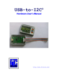
LPT-to-I2C SE Hardware Reference Guide http://www.i2ctools.com/ November 1, 2008 Information provided in this document is solely for use with the LPT-to-I2C SE product from SB Solutions, Inc. SB Solutions, Inc. reserves the right to make changes or improvements to this document at any time without notice. SB Solutions, Inc. assumes no liability whatsoever in the sale or use of this product, including infringement of any patent or copyright. No part of this document may be reproduced or transmitted in any form or by any means, electronic or mechanical, for any purpose, without the express written permission of SB Solutions, Inc., P.O. Box 4506, Cary, NC 27519-4506. Microsoft and Windows are registered trademarks of Microsoft Corporation. Other brand names are trademarks or registered trademarks of their respective owners. Copyright 2008 SB Solutions, Inc. All rights reserved. ii Table of Contents INTRODUCTION ................................................................................................................... 1 LPT-to-I2C SE Professional KIT CONTENTS .......................................................................... 1 DISCLAIMER AND WARRANTY ............................................................................................ 1 GETTING STARTED .............................................................................................................. 2 Assumptions .................................................................................................................... 2 Static Handling Precautions ............................................................................................. 2 MINIMUM SYSYEM REQUIREMENTS .................................................................................. 2 ADAPTER POWER REQUIREMENTS ..................................................................................... 2 INSTALLATION ..................................................................................................................... 2 LPT-to-I2C SE Software .................................................................................................... 2 LPT-to-I2C SE Adapter connection to computer parallel port......................................... 2 On-board EEPROM .............................................................................................................. 3 LPT-TO-I2C SE ADAPTER TO TARGET CONNECTION ........................................................... 3 HARDWARE DESCRIPTION .................................................................................................. 4 SOFTWARE UPDATES .......................................................................................................... 5 TECHNICAL SUPPORT .......................................................................................................... 5 TROUBLESHOOTING ............................................................................................................ 5 ii LPT-to-I2C SE Hardware User’s Manual INTRODUCTION The LPT-to-I2C SE Adapter connects to the standard DB-25 parallel port found on any IBM-compatible PC and provides bi-directional communication with I²C devices using the I²C protocol. The adapter can be powered either directly from the PC's parallel port or externally powered from the I²C target system. The on-board LED indicates the presence of power. If jumper JPWR is connected, then the Adapter will be self-powered and the LED will be powered from the parallel port. If jumper JPWR is removed, the Adapter is powered from an external source. The LED may be very dim or may not be illuminated for very low voltage (<1.9V) applications. The LPT-to-I2C SE software runs on Windows 95, 98, ME, NT, 2000, XP, XP64, Vista, and Vista64. It is compatible with any PC hardware having a minimum of a Pentium processor and a parallel port. A PCI-based parallel port add-in card is also supported. The software allows the user to select an EEPROM from a menu and also provides several Universal modes to allow communication with most I²C device. The LPT-to-I2C SE software is designed to operate only with the included hardware adapter and will not detect I²C parallel port adapters from other vendors. In addition, the LPT-to-I2C SE adapter provides a socketed on-board 256-byte EEPROM with direct connection to the I²C bus (power supplied by the PC parallel port). LPT-TO-I2C SE PROFESSIONAL KIT CONTENTS Parallel Port adapter with 256-byte EEPROM LPT-to-I2C SE software installation CD-ROM which loads the following files: Software license agreement LPT-to-I2C SE Professional user Registration Form LPT-to-I2C SE Software User’s Manual LPT-to-I2C SE Installation and User's Guide Hardware User’s Manual (this document) DLL User’s Manual DISCLAIMER AND WARRANTY Proper use of the LPT-to-I2C SE Professional kit is the sole responsibility of the user. SB Solutions, Inc. is not responsible for any damage resulting from misuse or improper installation. SB Solutions, Inc. will, at our option, repair or replace a defective LPT-to-I2C SE Adapter within thirty (30) days of the purchase date. Return shipping is responsibility of the user. 1 LPT-to-I2C SE Hardware User’s Manual GETTING STARTED Assumptions We are assuming the user of this product has experience with the I²C Bus protocol. The I2C Bus specification is a good source of detailed information about the I2C Bus. The complete specification can be downloaded from the Philips Semiconductors website. Static Handling Precautions The LPT-to-I2C SE Adapter contains CMOS devices that can be damaged by ESD. It is recommended to use a ground strap or touching the PC case or other grounded source before unpacking or handling the LPT-to-I2C SE adapter. MINIMUM SYSYEM REQUIREMENTS PC Pentium 60 processor (or equivalent), 8MB RAM, and 5MB of hard drive space Parallel port configured as bi-directional or EPP port Windows 95, 98, ME, NT4, 2000, XP, XP64, or Vista CD-ROM Drive for installation ADAPTER POWER REQUIREMENTS The LPT-to-I2C SE adapter can be used stand-alone since it obtains power from the PC parallel port. This allows the on-board I2C 256-byte EEPROM to be programmed and verified without the need for an external power source. When the LPT-to-I2C SE Adapter is connected to an I²C target system, power must be supplied from the target to the Adapter via one of the two 4-pin headers on the Adapter (Caution: ensure to connect these headers to the target correctly). Jumper JPWR must be removed when the LPTto-I2C SE Adapter is connected to an external target system. The power LED (PWR) will be illuminated for voltage above 1.9V, although it may be dim at the lower voltages. INSTALLATION LPT-to-I2C SE Software • Insert the LPT-to-I2C SE installation CD-ROM into the appropriate drive. • The installation software should automatically start. • If the installation software does not start automatically, double-click on the Setup.exe file on the CD-ROM LPT-to-I2C SE Adapter connection to computer parallel port 2 LPT-to-I2C SE Hardware User’s Manual • • Neutralize any ESD (static charge) by touching the bare metal on the rear of your computer before removing the LPT-to-I2C SE Adapter from the packaging. Connect the Adapter to an available parallel port. Caution: Some SCSI adapters also use the same DB-25 connector. Inadvertently using a SCSI port may damage the SCSI port or Adapter. ON-BOARD EEPROM The on-board 8-pin DIP socket supports I²C communication with the included EEPROM or other EEPROM devices. The default I²C address for this EEPROM socket is (0xA0), but the address can be altered by changing the position of the jumper A0 (address bit 0). The address will be 0xA0 if connected to ground and it will be 0xA2 when connected to Vcc. The use of the jumper allows you to change the address of the on-board EEPROM if the target system contains a device with an address conflicting with the default 0xA0. If the target system has devices which conflict with both addresses, the EEPROM should be removed to resolve the conflict. There is also a jumper connected to pin 7 (labeled WP) of the EEPROM allowing connection of pin 7 to Vcc or ground. Pin 7 is generally the Write Protect (WP) pin, with some devices being active high and others being active low. The EEPROM can also be replaced with a static RAM, like the PCF8570. In this situation, pin 7 should be connected to ground. LPT-TO-I2C SE ADAPTER TO TARGET CONNECTION When an external I²C peripheral is connected to the LPT-to-I2C SE Adapter, the power must be supplied by an external power supply through the four-pin connectors on the adapter. It is recommended to use header JP1 for the connection to the target system. Jumper JPWR must be removed. 3 LPT-to-I2C SE Hardware User’s Manual HARDWARE DESCRIPTION DB-25 Parallel Port Connector - plugs into the computer’s printer (LPT) port. JPWR (Power Selector) – is used to configure the power source for the board. When the jumper is connected, the board is self-powered (the power for the board is supplied by the PC parallel port). When the jumper is removed, the power must be supplied through the V+ pin. The voltage must be in the range of 0.9V to 5.5V. Note that at lower voltages (approximately less than 1.9V), the LED may not illuminate or may be dimly lit. PWR (Power Indicator) - is used to visually show there is power to the board. The LED may not be illuminated when a low voltage is applied to the board. The LED turns on when a voltage of greater than 1.8V is applied to the board. A0 (EEPROM Pin 1) - is usually the Address 0 (A0) address bit. This jumper allows the user to change the on-board EE address. WP (EEPROM Pin 7) - is usually a Write Protect (WP) input and may be active either high or low. This jumper allows the user to put the WP pin in the correct state for writing. You can also place a device like the PCF8570 static RAM in the EEPROM socket and then tie this pin low. EEPROM - is socketed to allow the user to use this hardware to program DIP EEPROMs. The EEPROM is a handy feature to verify the hardware/software are functioning correctly. It is also suggested to try the PCF8570 static RAM as this device does not require a Write Cycle time that is required by an EEPROM. Headers - there are two headers on the board with different pinning layouts to connect the LPTto-I2C SE hardware to the user's target system. Please be careful when you connect the target to the header since incorrect connection can potentially cause damage to the adapter, target, or pc. 4 LPT-to-I2C SE Hardware User’s Manual SOFTWARE UPDATES LPT-to-I2C SE has a built-in web-based update feature you can use to update the application. You can also download the updates manually at the following website: http://www.i2ctools.com/updates Check our website periodically for update announcements and information. TECHNICAL SUPPORT Technical Support for the LPT-to-I2C SE is available via email to [email protected]. TROUBLESHOOTING A "Privileged Instruction" error will be displayed if the software was installed on a Windows NT, 2000, XP, or Vista system without Administrative Privileges. If this error is observed, try re-installing the LPT-to-I2C SE software with Administrative Privileges. If the installer application doesn’t launch when the CD-ROM is inserted, then manually browse the CD-ROM and find the Setup.exe file in the root directory of the CD. Doubleclick on the Setup.exe file to start the installation process. LPT-to-I2C SE may not function correctly with mobile PCs that are mounted in docking stations. This is due to corruption of the I2C signal timing by the docking station. The software may not function correctly in systems containing more than one CPU. If LPT-to-I2C SE is not recognizing your Adapter, the parallel port of your PC may not be configured properly. Check your parallel port configuration in your BIOS setup during PC boot and the parallel port settings in Windows. It is best to use a standard bidirectional or EPP mode if available. Note that if the LPT-to-I2C SE Adapter is deriving its power from the computer’s parallel port, the LED may not illuminate until the LPT-to-I2C SE software has started. The LED may turn off when the software is exited. If you are experiencing communication errors to your connected I²C target system, make sure you are supplying external power to the adapter. Remove the Adapter from the PC parallel port and power-up your I²C target system with the LPT-to-I2C SE Adapter connected (via the I²C bus). The LED on the adapter should light if power is properly connected from the target system. The adapter functionality can be verified by disconnecting the I2C cable from the target and then attempt to program the on-board EEPROM using the 256x8 EEPROM with default address 0xA0 or 0xA2 depending on the setting for jumper A0. 5 LPT-to-I2C SE Hardware User’s Manual Excess I2C cable length or bus capacitance may cause bus errors or erratic I²C communication at full speed operation. If this occurs, reduce the bus frequency in the Options menu or reduce the length of the cables. If intermittent communication to the on-board EEPROM is experienced when the Adapter is self-powered from the PC parallel port, this may be caused by insufficient voltage from the PC motherboard (some parallel ports supply only 3.3V, especially on notebook computers). Connecting an external 3.3v or 5V source to one of the I2C headers on the Adapter should solve the problem. The Adapter has 4.7kΩ pull-up resistors on the I2C bus. Insure that additional pull-up resistors in the connected target system do not bring the pull-up resistance below 1.6kΩ (for 5V systems) or 1.1KΩ for 3.3V systems. Values below the minimum recommended values will violate the 3mA maximum bus current (IOL) specification and can potentially affect communication reliability. LPT-to-I2C SE monitors the communications on the I2C bus for proper operation of connected peripherals; any errors on the bus are detected and reported by the software. Bus communication is stopped if errors are detected and can be resumed when the (hardware) problem is corrected and the transmission retried. Keep the original LPT-to-I2C SE installation CD-ROM in the event the software needs to be re-installed. Future LPT-to-I2C SE updates from our Website will require a previous installation from the original media. If all else fails, email a description of the problem you are having to us at [email protected]. 6