1
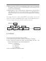
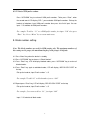
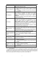
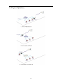
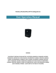
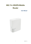
3G Fixed Wireless Terminal
FCT-355
User Manual
MAXCOMM CO., LTD.
Introduction
This User’s Manual mainly introduces the FCT-355 3G/GSM FWT_FXO converter
developed by our company. It includes the equipment type, performance and specification,
structure and application described in details in corresponding chapters.
This User’s Manual is the first edition. Our company reserves the right of upgrading the
edition.
FCT-355 3G/GSM FWT_FXO converter
USER MANUAL
Version: 1.0
Date: July 28, 2007
Copyright of First Edition © 2007
All rights reserved. No part of this document may be reproduced or used in any form or
by any means, including but not limited to photocopy, photograph, magnetic or other record,
without the prior agreement and written permission.
Very Important Notes Before installation
1. Please make sure the area where the converter is used can receive radio frequency
signal.
2. Please never use the equipment in an environment where exist explosive possibilities, for
example: gas station, chemicals, flammable gas, gas transport car or warehouse.
3. Please never use the equipment in an explosive area or a place where marked with “Turn
off Wireless Transmitting Device”.
4. This device should be avoided using in the hospital for medical electronics equipment such
as pacemaker and audiphones are easily disturbed by it.
5. There would gender electromagnetic field around the equipment, so please never put
other devices which can gender interference around the equipment, for example: television,
radio, computer, or magnetic memory media for example: compact disk etc.
6. Only its own suitable power adapter can be used in the device. Any other power adaptors
maybe damage this device and this kind of damage is out of the scope of maintenance.
7. If it is found that the device is unable to login GSM network, please make sure that the SIM
card is installed correctly.
8. The device does not identify the old SIM card of 5V and 1.8V.
9. Please make sure to use the GREY cable to connect between “Phone” port and your
telephone. Otherwise, you can not hear the dial tone and can not dial out any number
10. Please make sure the cable length between the device and your telephone is less than
100 meters
11. If this device is upgraded, we will not notice the user. The real appearance and function of
this product are based on the real substance. The EMI and ESD protection circuitry don't
response or input impedance of the audio input. The audio signal has a flat frequency
response between 300 and 3400 Hz. Outside this range, the response will attenuate
sharply.
1
1. Main description
1.1 Features
-
Conversion of wire & wireless communication
-
Auto-select economic route (LCR)
-
With LCD display for easy programming
-
Code Conversion Setting: Through the connection towards local PSTN line, the phone
calls will proceed with code-transfer dialing process
-
Volume modulating setting (1 - 5)
-
Polarity reversing function and 12 KHz built in (optional)
-
Definition of DTMF reversing signal
-
Limit of communicating time
-
GSM function of dialing out the prompt voice
-
When not connecting to Telephone Office line, GSM will provide the forced dial-out
function
-
Set up GSM extra dialing local code
-
Set up extra dialing local-code to PSTN
-
GSM isn't ready, call will be forced to dial out from PSTN
-
Setting of Dialing type Call-Transfer:
PSTN TO GSM, GSM TO PSTN, GSM call-Transfer setting time to PSTN out, DTMF
definition of reversed signal
-
GSM Frequency bands: Dual Band
EGSM 900 and DCS 1800 MHz
GSM 850/900/1800/1900 MHz (optional)
-
Specific Call Transfer setting:
GSM to PSTN: Assign mode (one stage dialing)
Free mode (two stage dialing)
PSTN to GSM: An Incoming call will be transferred to specify GSM Number
-
Call Transfer Restriction Setting (10 sets)
-
Short Code Setting (100 sets)
-
GSM Prefix Number Setting (30 sets)
-
Support Call ID ( DTMF)
-
Siemens TC-35 GSM Module
-
SIM Card Pin code disable/enable
2
1.2 Main panel and indicators
LED and Button
Color
Status
Description
Power
Red
On
Network
Green
Flash
Menu
-
-
Up
-
-
Move up the cursor or add number
Down
-
-
Move down the cursor or reduce number
Enter
-
-
Press this button to confirm and enter
Indicator for power supply working
Flash per 1 second means connection with
network OK.
Press this button to enter menu list or back
to top menu
Table 1.1 LED and Button
1.3 Rear panel and interfaces
3
Item
Interface
Description
Antenna
SMA
Connect with a whip antenna, 3 M RG58 cable
PTP/BD
RJ-45
For data (tariff) download
Printer
DB-9 (F)
Line
RJ-11
Connect to PSTN line
Phone
RJ-11
Connect to phone or payphone
ON/OFF
-
Power switch
BAT
-
For extended backup accumulator battery (6V/4AH)
DC 7.5V
-
AC/DC power adaptor port
For print out call list (Optional)
Table 1.2 Interfaces
2. Work mode
This device has 3 work modes: GSM only, PSTN only and PSTN/GSM
2.1 GSM only mode: A “GSM” mark will be displayed on the top right corner of LCD. User
can only dial and receive calls from GSM only under this mode.
2.2 PSTN mode: A “PSTN” mark will be displayed on the top right corner of LCD. User can
only dial and receive calls from PSTN line only under this mode.
2.3 PSTN/GSM mode: A “PSTN/GSM” mark will be displayed on the top right corner of LCD.
User can dial out either from PSTN or GSM under this mode. When user has set GSM
prefix number, the calls will switch to GSM routing automatically as a least lost router.
Note: If the power supply is broken or if the device is turned off, all the calls will go
through PSTN line.
3. Installation
3.1 Open the cover board of bottom side, then insert SIM card
3.2 Connect the GRAY cable to “Phone” port and telephone
3.3 Connect the White cable to “Line” port and PSTN line
3.4 Connect the whip antenna and power supply adaptor, to ensure voice quality, please
4
place the antenna more than 1.5 meter beyond the device
3.5 Turn ON the switch of the device, if the SIM card PIN code is disable, it needs about 10
to 45 seconds to finish initialization program (This time is based on the signal intensity of
the location)
3.6 If the SIM card PIN code is set Enable, when you switch on the device, LCD will display
“Input PIN CODE”. User should input correct PIN code through telephone, otherwise,
LCD will display “SIM PIN ERROR”
Note: If LCD display “SIM PIN ERROR”, user can reboot the device and input PIN
code again, but the device will lock SIM card when the inputting are incorrect three
times. If the SIM card is locked, please put it inside your mobile phone and input
correct PUK code to release it.
4. Make a call
4.1 Lift the handset or press “Hand Free”, to dial the number when you hear the dial tone
4.2 Dial a number, the device will choose the GSM/PSTN routing automatically. (Least Cost
Routing function)
4.3 If the number is a block number (See section 9. Block number setting), LCD will
display “BLOCK NUMBER / PLEASE HOOKON”, and then, busy tone will be heard.
5. Receive calls
5.1 When the device is under “PSTN/GSM” mode, user can receive calls from either PSTN
line or GSM mobile.
5.2 When a call is incoming, the telephone bell will ringing, pick up the handset or press
“Hand Free” to receive the call.
5.3 When user receives a GSM call under PSTN talking, “Beep” sound can be heard from
the telephone. That means there is a GSM call incoming, user can receive this GSM call
when he finished PSTN talking.
5
5.4 When user receives a PSTN call under GSM talking, “Beep” sound can be heard from
the telephone. That means there is a PSTN call incoming, user can receive this PSTN
call when he finished GSM talking.
5.5 When the device is used as a PABX extension, it maybe transfers a call from PSTN to
GSM mobile phone (You must set the transfer function). If the GSM mobile phone is
rejected receiving the call, the call will be returned to the telephone which is connecting
the device.
For example: If someone is calling in from PSTN line and extending to 803, the call
maybe will be transferred to GSM mobile phone. Suppose that the GSM mobile phone is
rejected receiving the call, then the call will be returned to telephone A.
PSTN Line
PABX
Telephone
Telephone
801
802
Device
Telephone A
Mobile Phone
803
6. Call Record
User can review the latest 20 records remain in the device
6.1 Press “Menu” key when the device is standby, LCD will display “1.Call Record”
6.2 Press “Enter” key to show the first record. The top row display “Call Type”,
Duration” and “Call Date/Time”, the second row display dial ID
Call Type: P – I: PSTN call in
P – O: PSTN call out
G – I: GSM call in
G – O: GSM call out
6.3 Press “UP/DOWN” key to show other records
6
“Call
7. Date and Time setting
7.1 Press “Menu” key when the device is standby
7.2 Press “UP/DOWN” key to choose “2.Date & Time”
7.3 Press “Enter” key, LCD will display “Day – Month – Year – Hour – Minute”, Press
“UP/DOWN” to set the Items and press “Enter” to save.
8. Work mode setting
8.1 Press “Menu” key when the device is standby
8.2 Press “UP/DOWN” key to choose “3.Work Mode”
8.3 Press “Enter” key, LCD will display “Single: GSM”, “Dual: PSTN/GSM” or “Single: PSTN”
8.4 Press “UP/DOWN” key to choose right work mode and press “Enter” key to save
8.5 GSM routing number setting
If you choose “PSTN/GSM” mode, the top row of LCD will display “Set GSM Dial code”,
the second row will display “Enter=Y/Menu=N”, press “Menu” key to return and press
“Enter” key to set GSM prefix numbers. The maximum GSM prefix numbers are 30
groups. The maximum length of each group is 10 digitals.
For example: “9” means when user dialing 9xxxxxxxx, calls will be sent out from GSM
routing.
8.5.1 Add GSM prefix number
Press “UP/DOWN” key to review all GSM prefix numbers. Press “Enter” to add GSM
prefix numbers. Pick up the handset of telephone, input GSM prefix number then press
# to finish input.
For example: To set “13” as a GSM prefix number, just input “13#”, press “Enter”
key to input another GSM prefix number.
7
8.5.2 Delete GSM prefix number
Press “UP/DOWN” key to review all GSM prefix numbers. Twice press “Enter”, when
the second row of LCD display “DEL:”, you can delete GSM prefix numbers. Pick up the
handset of telephone, input GSM prefix number then press # to finish input. You can
input “***#” to delete all GSM prefix numbers.
For example: To delete “13” as a GSM prefix number, just input “13#” then press
“Enter” key.. Press “Menu” key to return main menu.
9. Block number setting
Note: The block numbers are used for GSM routing only. The maximum numbers of
this setting are 30 groups, the maximum length of each group is 12 digitals.
9.1 Press “Menu” key when the device is standby
9.2 Press “UP/DOWN” key to choose “4. Block Number”
9.3 Press “Enter” key, LCD will display blocked codes, press “UP/DOWN” key to review all
blocked codes.
9.4 Press “Enter” key again to add block codes, LCD will display “ADD BLOCK CODE” on
the top.
Pick up the handset, input “Prefix number” + “#”
For example: To add “00” as block number, just set “00#”
9.5 Repeat press “Enter” key, LCD will display “DEL BOLOCK CODE” on the top
Pick up the handset, input “Prefix number” + “#”
For example: if you want to delete “00”, just input “00#”
Input “***#” to delete all block codes.
8
10. Call Transfer setting
This device can transfer calls either from PSTN line to GSM network or from GSM network to
PSTN line
10.1 To set PSTN to GSM transferring
10.2 Press “Menu” key when the device is standby
10.3 Press “UP/DOWN” key to choose “5. Call Transfer”
10.4 Set PSTN to GSM transfer
10.4.1 Press “UP/DOWN” key to choose “1. PSTN TO GSM”
10.4.2 Press “Enter” key, user can choose “Enable” or “Disable” and “Enable Free”.
If you select “Disable” mode, the device will not transfer the calls from GSM
If you select “Enable Assign” mode, when someone call the SIM card number of
this device, the device will transfer the call to an appointed PSTN number. Press
“Enter” key to set this number then press “#” to save and exit.
If you select “Enable Free” mode, when someone calls the SIM card number of this
device, the device will give a dail tone to prompt caller and let caller to continue
inputting destination number.
For example: When you set “PSTN TRANSFER TO” GSM number: 138xxxxxxxx If
someone is calling in from PSTN line, the call will be transferred to 138xxxxxxxx.
Note: If the GSM mobile phone is rejected receiving the call, the call will be returned to
the telephone which is connecting the device.
10.5 Set GSM to PSTN transfer
10.5.1 Press “UP/DOWN” key to choose “2.GSM TO PSTN”
10.5.2 Press “Enter” key, there are 3 modes can be chosen: “Disable”, “Enable Assign” and
“Enable Free”
If you select “Disable” mode, the device will not transfer the calls from GSM
If you select “Enable Assign” mode, when someone call the SIM card number of
this device, the device will transfer the call to an appointed PSTN number. Press
“Enter” key to set this number then press “#” to save and exit.
9
If you select “Enable Free” mode, when someone calls the SIM card number of this
device, the device will give a “Beep” sound to prompt caller and let caller to
continue inputting destination number. The caller can also input short codes (See
section 12. Short codes setting) when he heard “Beep” sound. Press “Enter” key
to set this number then press “#” to save and exit.
Note: For GSM to PSTN transfer function, you must set “Permitted Code” in “6.
TRANS RESTRICT”. Only after you have set the permitted GSM codes successfully,
the calls can be transferred, otherwise, the telephone which is connecting the device
will ring.
11. Transfer restrict setting
Note: Only when someone calls the SIM card number of the device, this function is
available. The maximum number of this setting is 30 groups, the maximum length of
each group is 12 digitals
11.1 Press “Menu” key when the device is standby
11.2 Press “UP/DOWN” key to choose “6. TRANS RESTRICT”
11.3 Press “Enter” key, LCD will display permitted codes, press “UP/DOWN” key to review all
permitted codes.
11.4 Press “Enter” key again to add permitted codes, LCD will display “ADD PERMIT CODE”
on the top.
Pick up the handset, input “Prefix number” + “#”
For example: To add “138” as a permitted number, just set “138#”.
When the SIM card of this device received a call from 138xxxxxxxx, the device will
transfer the call to PSTN line (See section 10.5 Set GSM to PSTN transfer)
11.5 Repeat press “Enter” key, LCD will display “DEL PERMIT CODE” on the top
Pick up the handset, input “Prefix number” + “#”
For example: if you want to delete “138”, just input “138#”
10
Input “***#” to delete all permitted codes.
12. Short code setting
Note: The maximum number of this setting is 100 groups, the maximum length of each
group is 16 digitals. When you set the short codes, you can use “Short code” + “#” to
dial out.
12.1 Press “Menu” key when the device is standby
12.2 Press “UP/DOWN” key to choose “7. SHORT CODE”
12.3 Press “Enter” key, LCD will display “Short Code XX”, press “UP/DOWN” key to review
all short codes.
12.4 Press “Enter” key again to edit short codes, LCD will display “EDIT CODE XX” on the
top.
Pick up the handset, input “Short Code” + “#”
For example: To edit NO.06 “13823709455” as a short number, press “UP/DOWN”
key to choose “EDIT CODE 06”, set “13823709455#”, then press “Enter” key to
update . So, when you want to dial “13823709455”, you can just dial “06#”
12.5 Press “UP/DOWN” key, you can set another short code.
13. GSM Volume setting
There are 5 levels can be adjusted for microphone voice and speaker voice. The default
setting is ‘Microphone level: 3’ and “Speaker level 3”
13.1 Press “Menu” key when the device is standby
13.2 Press “UP/DOWN” key to choose “8. GSM VOLUME”
13.3 Press “Enter” key, LCD will display “VOLUME MIC/SPK” on the top
13.4 Pick up the handset, press “UP/DOWN” key to delete previous setting, input new value
from telephone. The first value is for transmission (Microphone) and the second value is
for receiving (Speaker). The range of inputting value is 1 to 5.
13.5 Press “Enter” key to save and exit.
11
14. Other Parameters setting
14.1 Press “Menu” key when the device is standby
14.2 Press “UP/DOWN” key to choose “9. SET PARAMETER”
14.3 Press “Enter” key to other set parameters, press “UP/DOWN” key to select items
14.4 Conversation Time Out setting
14.4.1 Pick up the handset, press “UP/DOWN” key to delete previous setting
14.4.2 Input a new value from 00 to 99. The maximum conversation time is 99 minutes. “00”
means unlimited conversation time.
For example: If you set the value “05”, it means all the conversations are limited in
5 minutes.
14.5 GSM code length setting
14.5.1 Pick up the handset, press “UP/DOWN” key to delete previous setting
14.5.2 Input a new value from 00 to 15. When the value is less than “3”, the GSM calls will
be sent out after 6 seconds (You can press # to send it out immediately). Otherwise, if
the length of GSM numbers equal to this setting value, the calls will be sent out after 2
seconds.
14.6 Polarity reversal setting
14.6.1 Press “UP/DOWN” key to select “Disable” or “Enable”
14.6.2 Press “Enter” key to save and exit
12
14.7 GSM if No PSTN setting
14.7.1 Press “UP/DOWN” key to select “Disable” or “Enable”
When you set “Enable”, if the power supply is broken or if the device is turned off or the
GSM part has been get some damage, the calls will be allowed to go through PSTN line.
14.7.2 Press “Enter” key to save and exit
14.8 PSTN if No GSM setting
14.8.1 Press “UP/DOWN” key to select “Disable” or “Enable”
When you set “Enable”, if the PSTN part has been get some damage, the calls will be
allowed to go through GSM routing.
14.8.2 Press “Enter” key to save and exit
14.9 Default setting
Pick up the handset and then input “886432#” to reload default setting of the factory
mode. The detail settings are shown as follow:
Work Mode:
GSM/PSTN
Transfer setting:
Disable
Conversation Time Out: 00
GSM Code Length:
00
Polarity Reversal:
Disable
GSM if No PSTN:
Enable
PSTN if No GSM:
Enable
14.10. Convert Code setting (IP code setting)
This convert code setting is used for GSM routing only, the maximum numbers of convert
codes are 30 groups, the maximum length of each group is 7 digitals.
14.10.1 Press “Menu” key when the device is standby
14.10.2 Press “UP/DOWN” key to choose “7.Convert Code”
13
14.10.3 Press “Enter” key, LCD will display convert code setting, press “UP/DOWN” key to
review all convert codes.
For example: “0 ->179510” means “17951” is a GSM IP code, after set this code,
when you dial 0xxxxxxxx, it will send out 179510xxxxxxxx
14.10.4 Press “Enter” key again to add convert codes. LCD will display “ADD CONVERT
CODE” on the top.
Pick up the handset, input “Prefix number” + “#” + “Converted Number”, then press “#”
to save and ready to add another convert code. Press “Menu” key to return.
For example: if you want to convert “95” to “0”, just input “95#0#”. After set this
code, when you dial 95xxxxxxxx, it will send out 0xxxxxxxx
14.10.5 Repeat press “Enter” key, LCD will display “DEL CONVERT CODE” on the top row
Pick up the handset, input “Prefix number” + “#”
For example: if you want to delete “95
-> 0”, just input “95#”
Input “***#” to delete all convert codes.
15. Technical Parameters
15.1 Power supply
AC Input voltage:
160V to 280V
Power adaptor output:
DC7.5V / 1.5A
Backup battery:
6V / 4AH Lead-Acid battery
(Optional accessory)
Maximum charge current:
600 mA
DC input voltage range:
7.5V to 10V DC
Maximum DC current:
700 mA (DC7.5V. external charge current)
15.2 Working environment
Working temperature:
0 to +45 ℃
Relative humidity:
10% to 95%
14
Environment noise:
<60dB (A)
Atmospheric pressure:
86 to 106 KPa
15.3 GSM parameters
Support HSDPA/UMTS/EDGE/GPRS/GSM
Triple-band HSDPA(UMTS): 850/1900/2100MHz
Quad-band EDGE/GPRS/GSM: 850/900/1800/1900MHz
HSDPA downlink : 3.6Mbps
WCDMA(UMTS) uplink : 384kbps
EDGE data : 237kbps downlink and 118kbps uplink
GPRS data : 85.6kbps downlink and 42.8kbps uplink
SIM card mode:
3.0 V
Antenna impedance:
50 Ohm
15
16. Appendix
16.1 Definition of grey cable
If you want to connect the grey cable to a 2 wires telephone / payphone, the correct
connection method is shown as follow:
16.2 Trouble Shooting
Trouble phenomenon
Can not dial number.
“Network”
flickering fast
indicator
Solving Methods
1. SIM card has been locked: insert the SIM card into a
mobile phone, if the card has been locked, there will
display prompt in the mobile LCD which requires inputting
PUK code. Input PUK code, then input a new PIN code
and set the new PIN code as 1234. If the equipment has
reciprocal SIM card lock function, the PIN code of the SIM
card should be opened. Or the PIN code of the SIM card
should be locked to avoid SIM card being locked. After
unlocking the SIM card, insert the SIM card into the
equipment and turn the equipment on.
2. Can not detect any SIM card: Please check the contact
spring of the SIM card holder or the contact point of the
SIM card to see whether there is abrasion, ageing or stain
in the SIM card. And then install the SIM card again.
3. Bad connection of antenna or antenna rupture: please
check whether the core of the antenna is well connected
or change the antenna.
4. Telephone setup: Please check whether the dialing system
is DTMF, or whether the phone lock is opened.
1. Bad connection of antenna or antenna rupture, please
check whether the core of the antenna is well connected
or change the antenna.
2. Weak signal. Please adjust the position of antenna and
observe signal quality of LCD screen to get the best call
effect
16
LCD display “Error PIN”
“Power” indicator OFF
No dialing tone
Interference
No
incoming
display
call
SIM card locked, user access be refused. Please connect
with vendor or owner to unlock.
1. Connection problem of power adaptor or backup battery.
Please check the status of power adaptor or backup
battery
2. The adaptor or main board is burned. Please contact with
your provider
1. It is possible that the grey cable isn’t used to connect with
your telephone or payphone. You should use this special
cable to connect between the terminal and telephone
/payphone. The definition of the gray cable is shown in
section 16.1
2. Bad line connection: Please check whether the electrical
function of the line is ok.
1. Antenna interference: Please place the antenna away from
the power line and telephone line and telephone as far as
possible. Antenna, power line, telephone line can not be
bound together to lay out. If there is a necessary cross
connect, please make it to be vertical cross connect. There
should be no transmission equipment around the equipment
to avoid interference between each other.
2. Bad connection of crystal connector of telephone straight
line and coil line, please replace them.
1. The incoming call display function of SIM card has not
been opened: Please contact with SIM card operators to
open the function.
2. No incoming call display: Please change another telephone
which possesses DTMF incoming call display function.
Voice quality bad during
calling or echo can be
heard
1 Adjusting smaller volume of telephone / payphone
2 Try to change a better telephone or handset
3. Weak signal. Reference ““Network” indicator flickering fast”
partly content
Only toll free number
can be dialed out
It is possible the balance money not enough. Please charge
money for your SIM card
One way conversation
No ring when calls
incoming or can not
receive any incoming
calls
Off hook and busy tone
1. Failure telephone or payphone. Please check your
telephone or payphone
2. No metering pulse for payphone. Please contact with your
provider
1. Failure telephone or payphone. Please check your
telephone / payphone or change it
2. Terminal set error or terminal failure. Please contact with
your provider
Please check the network
Note: Special statement:
Any result due to the action of changing the parameters of the equipment without the
certification of our company has no relation with our company. And please never randomly change
the SIM card to test the equipment for the users who has set the reciprocal SIM card lock function.
Please use the original card to avoid unnecessary trouble caused by SIM card.
17
16.3 Typical Applications
18