1
Innovator 11
Manual classiX
A Models
Setting Up Models
www.mid.de
Manual classiX A Models–Innovator 11 (version 11.3)–Edition December 2010
Copyright © 1986-2010 MID GmbH Nuremberg, Germany. All rights reserved.
The copyright for Innovator software and the accompanying documentation is the property of MID GmbH.
Any reproduction or publication – in part or in whole – requires the written authorization of MID GmbH. Any violations
of this will be prosecuted in accordance with copyright protection laws.
Registered trademarks and trade names are used in this documentation. Protection provisions apply to same, even if they are
not marked as such.
The content of the documentation is for information purposes only and MID GmbH reserves the right to change it at any
time without prior notice. MID GmbH will not be held liable for any damages arising from the use of the software or
documentation.
Contents
Contents
Part A Setting Up Models ..................................................................................................... A-1
A-1 Managing Users, Groups and Rights ..................................................................................... A-3
A-1.1
User Rights, Group Rights, Privileges and Access Rights ..................................................... A-3
A-1.2
Assigning Access Rights .................................................................................................................. A-5
A-1.2.1 Logging In and Out as Model Administrator ...................................................................... A-5
A-1.2.2 Managing User Groups .............................................................................................................. A-7
A-1.2.3 Managing Users ............................................................................................................................ A-9
A-1.2.4 Transferring User Information to Another Model ........................................................... A-12
A-1.2.5 Managing Log-Ins ...................................................................................................................... A-14
A-1.2.6 Assigning Privileges and Element Rights to User Groups .............................................. A-16
A-1.2.7 Changing a Password ................................................................................................................ A-18
A-2 Opening and Configuring Models ........................................................................................ A-19
A-2.1
Using Models ................................................................................................................................... A-19
A-2.2
Configuring Models....................................................................................................................... A-21
A-2.2.1 Overview of Model Configuration ........................................................................................ A-21
A-2.2.2 General Settings .......................................................................................................................... A-23
A-2.2.3 Element Fonts ............................................................................................................................. A-29
A-2.2.4 Element Colors ........................................................................................................................... A-29
A-2.2.5 Labels............................................................................................................................................. A-30
A-2.3
Loading Model Options ............................................................................................................... A-31
A-2.4
Saving Model Options .................................................................................................................. A-32
A-3 Structuring Models with Packages ........................................................................................ A-35
A-3.1
Working with Packages ................................................................................................................ A-36
A-3.1.1 Creating and Changing Packages .......................................................................................... A-37
A-3.1.2 Copying and Moving Packages .............................................................................................. A-41
A-3.1.3 Modifying the Hierarchy of Packages .................................................................................. A-43
A-3.1.4 Deleting Packages ...................................................................................................................... A-44
Copyright © 2010 MID GmbH
I
Contents
A-3.2
Modeling Dependencies Between Packages in Package Diagrams................................... A-45
A-3.2.1 Creating and Opening Package Diagrams .......................................................................... A-45
A-3.2.2 Creating and Adding Package Diagrams ............................................................................. A-46
A-3.2.3 Producing Relationships Between Packages....................................................................... A-48
A-3.2.4 Deleting Packages or Removing them from a Diagram .................................................. A-53
A-3.3
Creating Package Structures........................................................................................................ A-53
A-3.3.1 Automatically Creating Package Structures ....................................................................... A-54
A-3.3.2 Importing Package Structures ................................................................................................ A-55
A-3.3.3 Exporting Structure Templates .............................................................................................. A-58
A-3.4
Making Specifications to Packages............................................................................................ A-60
A-3.4.1
A-3.4.2
A-3.4.3
A-3.4.4
Setting Permissible Elements .................................................................................................. A-60
Creating New Stereotypes and Properties for Packages .................................................. A-64
Creating Filters for Son Packages ........................................................................................ A-67
Redirecting Elements once Created in a Certain Package .............................................. A-68
A-4 Storing Specifications for Diagrams and Elements ..................................................... A-73
A-4.1
Defining Stereotypes and Properties of Elements ................................................................. A-75
A-4.1.1 Expanding, Modifying and Deleting Properties ............................................................... A-76
A-4.1.2 Creating, Modifying and Deleting Property Values ........................................................ A-78
A-4.2
Creating Filters for Selecting and Displaying Elements ...................................................... A-81
A-4.2.1 Creating Filters for Selection Restriction of Elements..................................................... A-81
A-4.2.2 Creating Filters for Displaying Elements ............................................................................ A-84
A-4.3
Providing Templates for Diagrams, Elements and Display Types ................................... A-86
A-4.3.1 Creating, Modifying and Deleting Templates–General .................................................. A-87
A-4.3.2 Creating Packages for Model Elements and Packages ..................................................... A-91
A-4.3.3 Templates for Relationships .................................................................................................. A-93
A-4.3.4 Creating and Changing Display Templates........................................................................ A-96
A-4.3.5 Creating and Changing Diagram Templates...................................................................... A-99
A-4.3.6 Setting Diagram Displays ...................................................................................................... A-101
A-4.3.7 Setting the Contents of Class and Component Diagrams ............................................ A-104
A-5 Putting Together and Calling Verification Routines................................................ A-109
A-5.1
Putting Together or Editing Verification Routines ............................................................ A-109
A-5.2
Loading and Saving a Model Option's Verification Routines ......................................... A-113
A-5.3
Deleting Verification Routines ................................................................................................ A-114
A-5.4
Calling Verification Routines.................................................................................................... A-114
Index .................................................................................................................................................................. A-117
II
Manual classiX A Models Innovator 11
Part A Setting Up Models
Normally more than one person works in the models which you create using Innovator editions. The tasks and responsibilities which each team are
in charge of can be very varied.
You must first consider the following questions before beginning a new
model:
• Which areas of responsibility are there and which team members are in
charge of each one?
• Are there already similar models which could at least serve in part as a
basis or does the model need to be completely made from scratch?
• Which structure should form the basis of the work in the model?
• e.t.c.
These aspects are relevant for the use and preparation of templates for new
models and for organizing access rights.
This part of the manual addresses your options when setting up your model and how to enable individual members of your team to work in a seamless and specific way.
Prerequisites for setting up a model include
Note
• A started license server
• A started repository server
Only then does the model browser enable you to open a model.
You can find information about starting license and repository servers, as
well as about administration of repositories and models in the administrator manual.
The following chapter will outline Innovator functions which are largely
independent from the Innovator edition used. You will learn (normally as
model administrator) how to:
• Assign rights in the model (see chapter A-1, "Managing Users, Groups
and Rights", page A-3)
• Set model options (see chapter A-2, "Opening and Configuring Models", page A-19)
• Use packages for structuring the model (see chapter A-3, "Structuring
Models with Packages", page A-35)
Copyright © 2010 MID GmbH
1
• Set properties for diagrams and elements (see chapter A-4, "Storing
Specifications for Diagrams and Elements", page A-73)
• Set and implement model verification (see chapter A-5, "Putting Together and Calling Verification Routines", page A-109)
Read about Innovator's basic functions in the Manual classiX
B Operations.
Read about versioning model elements in the Manual
Version Management.
Read about comparing model elements in the Diff Utility Manual.
2
Manual classiX A Models Innovator 11
A-1 Managing Users, Groups and Rights
Every user in Innovator automatically has read-only rights for all model information. However, the user must first be assigned the rights to make access changes.
Access rights to a model's element are assigned in Innovator at the groups
level. Once the user is assigned to a group, he then has access rights to this
group.
In addition, some operations can be applied to elements; for these, special
privileges are required. These are also assigned in Innovator at the groups
level.
A-1.1
User Rights, Group Rights, Privileges and Access Rights
Access changes to a model's data are controlled via a multi-level rights system.
To have access to the contents of a model, you must log-in with a user
name. This applies both for if you want to have read-only rights or wish to
make modifications. The user name must already exist in the model.
A user name can have a password for protecting access to the model.
The (model) administrator is available in every model as default. All rights
are automatically linked to this user name, which is necessary for administration of access rights and model configuration.
User
Every user can be assigned to no, one or various groups, which each determine the rights of the group members. The model administrator determines who is assigned to a group. A user can modify an element if one of
the groups he belongs to has access rights for this element.
Group
A user who does not belong to a group cannot modify an element.
Note
Copyright © 2010 MID GmbH
3
A-1 Managing Users, Groups and Rights
Privileges
Access to a model's elements–i.e. the right to make changes in them–is
normally controlled via packages. In addition, some operations can be applied to elements; for these, special privileges are required.
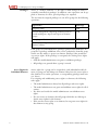
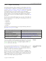
The user must be assigned privileges via one of his groups for the following
operations:
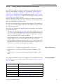
Operations
Privilege
Assigning labels
LBL
Version management: importing elements from versioned model parts, import and export of element
groups
VM
Managing verification routines
VFY
Visibility of configuration model in the Innovator
Business edition
CFG
Each group can individually have privileges granted and withdrawn. If a
group has a privilege withdrawn, then a user (exclusively) from this group
cannot use this mode to operate an element. Privileges take precedence
over access rights. If the privilege is reassigned, the existing access rights
still apply.
• Only the model administrator can grant or withdraw privileges.
• All privileges are granted when a group is created.
Access Rights for
Individual Elements
4
Access rights for a group can be assigned for each individual model element. A group can only change an element if they have the access right to
that element. For certain operations, a corresponding privilege must exist
(see above)
For assigning and withdrawing access rights to elements, the following
rules apply:
• The model administrator always has all privileges and access rights.
• The model administrator can grant and withdraw access rights for all elements.
• No other user besides the model administrator can withdraw access
rights.
• If a user creates an element, then all groups which the user belongs to
obtain access rights for this element.
• If the user has access rights to an element, he can grant access rights for
that element to any group.
Manual classiX A Models Innovator 11
A-1.2 Assigning Access Rights
A-1.2
Assigning Access Rights
You can assign access rights as both a model administrator and a user. The
administrator can assign access rights for the entire model. On the other
hand, a user can only access elements of other user groups if he has the
same access rights. However, a normal user cannot withdraw access rights.
Rights/mode assignment is possible on two levels in Innovator: Some operations (label assignment, versioning and visibility of configuration models) have privileges i.e. a group of users can carry out the tasks assigned to
them. Rights are also stored for individual elements. These rights are preassigned by the user assigned to the group who created this element.
You must have administrator rights for the model to create, assign or modify a user or a group (see chapter A-1.2.1, page A-5).
If users and groups already exist, you can make assignments in any order.
In contrast, if no information is available or this information is incomplete,
proceed with this order:
• Log-in as model administrator.
• Create groups.
• Grant the groups their required privileges.
• Create user names.
• Assign one or more user names to the groups.
If your network's user management uses the Lightweight Directory Access
Protocol (LDAP), you can load the user data you require from this source.
You can store specifications for users, groups and privileges in a configuration file. You can load the file to as many other models as you require, so
that the specifications are also available in new models.
A-1.2.1
Procedure
Logging In and Out as Model Administrator
You can assign access rights to administration tasks for each model in
Innovator.
The administrator first needs to decide which user belongs to which group
and which operation can be used by which group.
In addition, various configurations can be stored in each model. These are
loaded when a model is installed, but can also be modified afterwards. You
require administrator rights to make all of these modifications.
You can find all administration commands for user management in the
model browser in the Model>Administration submenu.
Copyright © 2010 MID GmbH
An Administrator's
Tasks
5
A-1 Managing Users, Groups and Rights
You can find all model configuration commands in the model browser in
the Model>Configuration submenu.
Model administrator is a status in Innovator which can be assigned to each
defined user in a Innovator model. There are two ways to gain administrator rights:
A: Log-in as administrator in a model when starting the model.
B: Upgrade your status to include administrator rights when working in the
model.
Note
An administrator password can be set for each model (see chapter A1.2.7, page A-18).
The models in the demo repository have the administrator password
admin.
Logging-In as
Administrator
You can select yourself to be administrator when logging-in to a model,
thereby gaining all of its rights.
How to proceed
To log-in as administrator in the model:
» Open the model browser in Innovator's program group.
The dialog box Model/Login appears.
» Activate the option button Administrator.
» If applicable, enter the administrator password in the field Password.
» Close the dialog box with [Login].
Upgrading Your Status
to Include
Administrator Rights
If you are already working in the model as a user, you can upgrade your access rights to administration without needing to log-out of the model. This
means that as many users as required can work as administrator.
How to proceed
If you are already logged-in with your user name in the model and now
want to gain administrator rights:
» Go to the model browser and select Model>Administration>Login....
The dialog box of the same name appears.
» Enter the password set for administrator in the field Password. Please
note that the password is case sensitive. If no password was assigned,
then leave the field empty.
6
Manual classiX A Models Innovator 11
A-1.2.2 Managing User Groups
» Confirm your entry with [OK].
The icon in front of the user name becomes a key in the status bar.
The way in which you log-out as administrator depends on how you
gained administrator rights:
Logging-Out as
Administrator
A: If you logged-in as administrator using the model, you need to log-out as
this user and then log-in again–as another user.
B: If you only upgraded your access rights to administrator rights, you can
simply withdraw these rights.
How to proceed
To log-out as administrator and log-in again as another user:
» Select Model>Logout in the model browser.
Your access to the model is withdrawn. You can log-in again as another
user.
How to proceed
To withdraw administrator rights again:
» Jump to the model browser and select Model>Administration>Logout.
The icon in front of the user name becomes a head in the status bar.
A-1.2.2
Managing User Groups
Access rights to model elements are assigned to user groups. This means
that all users who belong to these groups have element rights. The following section will explain how you set up and manage user groups. Read how
to assign privileges and element rights to user groups on page A-16.
How to proceed
To be able to manage user groups, you need administrator rights:
» Go to the model browser and log-in as administrator (see chapter A1.2.1, page A-5).
» Select Model>Administration>Manage User...
The dialog box of the same name appears.
» Select the tab Groups.
Copyright © 2010 MID GmbH
7
A-1 Managing Users, Groups and Rights
Creating User Groups
You can create as many user groups as required for your model.
How to proceed
To create a new user group:
» Enter the name of the new group in the field Group list. Ensure that
the name does not already exist in the list box Group list.
» Click on [New].
The new name appears in the Group List.
How to proceed
If user names are already defined, you can assign members to the new
group. All users which are defined in the model but not yet assigned to a
current group are listed in the Group Members drop-down list. Read
how to create a new user in chapter A-1.2.3, page A-9.
» Select a user name in the Group Members drop-down list and click on
[Add].
The user appears in the new group.
» Add all user names which you want to include in the group in the same
way.
Modifying User
Groups
You can rename a user group or modify its list of members.
How to proceed
To rename a user group:
» Select the group which you want to rename in the list box Group
list.
» Enter a new name in the field Group list.
» Click on [Rename].
The group is renamed.
How to proceed
To remove a user from the list of members:
» Select the group which you want to remove a member from in the list
box Group list.
» Select the user name which you want to remove from the list in the list
box Group members.
» Click on [Remove].
The name is removed from the list.
8
Manual classiX A Models Innovator 11
A-1.2.3 Managing Users
If you want to delete a user group, all users which were previously assigned
to the group will have their privileges for this one group withdrawn. Rights
which these users have for another group remain unaffected.
Deleting User Groups
How to proceed
To delete a user group:
» Select the group which you want to delete in the list box Group list.
» Click on [Delete].
The group is deleted.
» Click on [Close] to leave the dialog box.
A-1.2.3
Managing Users
To log-in a user to a model, his name must first be made known in the
model. You can set which rights the user should have within the model by
assigning them a user group. To do this, the user group must already exist
(see chapter A-1.2.2, page A-7).
As administrator, you cannot see a user's password. However, you can delete a user's password.
If a user has locked elements in a model and cannot e.g. be contacted, you
can log them out of the model. This means that all elements which the
user had locked will be available for other users once again.
How to proceed
To be able to manage users, you need administrator rights:
» Go to the model browser and log-in as administrator (see chapter A1.2.1, page A-5).
» Select Model>Administration>Manage User...
The dialog box of the same name appears.
» Select the tab Users.
You can create as many users as required for your model.
If your network's user management uses the Lightweight Directory Access
Protocol (LDAP), you can load user data your require from this source (see
page A-12).
Copyright © 2010 MID GmbH
Manually Creating
Users
9
A-1 Managing Users, Groups and Rights
How to proceed
To create a new user:
» Enter the user's name in the field User list. Ensure that the name
does not already exist in the list box User list.
» Click on [New].
The new name appears in the User List.
Note
The newly defined user has not yet been assigned a user group. Users
who are not assigned to a group can view all model content, but do not
have the right to modify or create new elements. Access rights can only
be assigned by user groups.
How to proceed
If groups are already defined, you can assign the new users to one of the
groups. All groups which are defined in the model which the user is not yet
assigned to are listed in the drop-down list Group membership. Read
how to create new groups in chapter A-1.2.2, page A-7.
» Select a group name from the drop-down list Group membership and
click on [Add].
The user appears in the group.
» Add all groups which you want to assign to the user in the same way.
Modifying Users
You can rename a user or modify its list of groups. Read how to add other
users in the section "Manually Creating Users", page A-9.
You cannot modify the user ADMIN.
How to proceed
To rename a user:
» Select the user which you want to rename from the list box User list.
» Enter a new name in the field User list.
» Click on [Rename].
The user is renamed.
How to proceed
To remove a group from the list of groups:
» Select the user whose group membership you want to change from the
list box User list.
10
Manual classiX A Models Innovator 11
A-1.2.3 Managing Users
» Select the group which you want to remove from the list in the list box
Group membership.
» Click on [Remove].
The name is removed from the list.
You can delete user names as long as the user is not currently logged-in to
a model.
Deleting User Names
How to proceed
To delete a user name:
» Select the user name which you want to delete in the list box User
list.
» Click on [Delete].
The name is deleted.
If a user forgets his password, as administrator you cannot reconstruct this
password. You can, however, delete the password and regain access for the
user to the model in this way.
Deleting User
Passwords
How to proceed
To delete a user password:
» Select the user name whose password you want to delete in the list box
User list.
» Click on [Clear password].
The user's password is deleted. He can only log-in to the model again
without a password and then, if necessary, define a new password.
You can log a user out of the model and, in doing so, rerelease the elements
which were locked by the user for other users.
Logging-Out Users
from a Model
How to proceed
To log-out a user:
» Select the user name which you want to log-out of the model in the list
box User list.
» Click on [Logout].
The user is logged-out, all elements which were locked by the user are
unlocked.
Copyright © 2010 MID GmbH
11
A-1 Managing Users, Groups and Rights
How to proceed
Once you have finished:
» Close the dialog box with [Close].
A-1.2.4
Transferring User Information to Another Model
You can store specifications for users and user groups in a file and load
them to another model. The file is stored in the respective repository server's project directory ($INOPRJ). As long as the models are in repositories
whose servers physically work on the same environment, then user data can
be directly transferred.
Saving User
Information
You can transfer the following data to another model in the same way:
• User groups
• Assignment of privileges to user groups
• Users and their assignments to user groups
• User passwords
Note
The administration password is not stored in the file.
How to proceed
To store user information:
» Go to the model browser and log-in as administrator (see chapter A1.2.1, page A-5).
» Select Model>Administration>Manage User...
The dialog box of the same name appears.
» Select the tab Save.
» Select a file name from the drop-down list Configuration file or
enter one. Do not include the file name extension.
» Click on [Save].
The file is stored in the repository server's $INOPRJ/config/user
directory of the current Innovator environment. It has the file extension
.cfg.
Loading User
Information
12
You can load user information from the network (only names) or from other models (names, as well as groups, assignments etc.).
Manual classiX A Models Innovator 11
A-1.2.4 Transferring User Information to Another Model
If your network's user management uses the Lightweight Directory Access
Protocol (LDAP), you can load user data from this source (only for Windows (.NET Framework required) and Solaris (SPARC and PC)). Therefore, other data (server, port and other attributes), which you can request
from the network administrator, are required.
How to proceed
To import users in the user list via LDAP:
» In the model which you want to load data to, go to the model browser
and log-in as administrator (see chapter A-1.2.1, page A-5).
» Select Model>Administration>Manage User...
The dialog box of the same name appears.
» Select the tab Load.
» Click on the [LDAP...] button.
The dialog box Administration/Manage User appears.
» In the field Server, enter the LDAP server's address using <name>
.<company>.<domain> format.
» Enter the port number in the field Port. This is usually the number
389.
» If the server requires authentication, enter the log-in parameter for the
authentication in the field Bind DN on the LDAP server in cn=<company>,dc=<domain> format and the necessary password (if applicable) in the same field.
» In the field Base DN, enter the base DN as the starting point in the
LDAP directory structure using dc=<company>,dc=<domain> format.
» Select how you wish the search results to be displayed from the dropdown list Attribute. You can choose between sn (surname), cn
(common name) and displayName.
» Click on the [Reload] button.
The user data are loaded via LDAP and only those which have no identical entries are shown in the drop-down list. (Please note that this also
depends on the selected way the search results are displayed, as this produces different results.)
» Activate the check box next to the user who you want to import in the
model. If applicable, use the [Select all] or [Select none] buttons to do this.
» Click on the [Import] button.
The selected users are imported in the model.
If you load a file with user information which you saved in a model into
another model, entries and assignments of the same name which already
exist there are overwritten using the file's data. Entries which exist in the
new model but not in the file are not overwritten.
Copyright © 2010 MID GmbH
13
A-1 Managing Users, Groups and Rights
How to proceed
To load user information from another model:
» In the model which you want to load data to, go to the model browser
and log-in as administrator (see chapter A-1.2.1, page A-5).
» Ensure that the file with the user information is stored in the current repository server's $INOPRJ/config/user directory.
» Select Model>Administration>Manage User...
The dialog box of the same name appears.
» Select the tab Load.
» Select the required file from the drop-down list Configuration
file.
» Click on the [Reload] button.
The selected user information is loaded in the current model.
A-1.2.5
Managing Log-Ins
User log-ins to a model and group log-ins to a model can be locked or released using Innovator Web. To do this, you must be logged-in as the administrator in the model.
Permitting User
Log-In
You can permit or prevent user log-ins for an individual model in the Users tab. The Logged On column in the table shows which users are
logged-in and whether they have administrator rights. The Locks column
shows the number of model elements locked by a user.
How to proceed
To permit new user log-ins to a model:
» In the model browser, select Model>Administration>Manage Logins...
The dialog box of the same name appears.
» Open the tab Users and activate the check box Allow user login.
» Click on [Apply].
Other users can log-in to the model.
Logging-Out
Logged-In Users
14
You can also remove existing log-ins in the Users tab. This function enables the administrator to be logged-in as the only user and carry out comprehensive work to the model.
Manual classiX A Models Innovator 11
A-1.2.5 Managing Log-Ins
How to proceed
To log-out users from the model:
» Open the tab Users and activate the check box Logout all users.
» Click on [Apply].
The users logged-on to the model are logged-out.
The ADMIN user cannot be logged-out in the Administration/Manage Logins dialog box. This is only possible with Model>Administration>Manage User....
Note
Group log-ins to the model via Innovator Web can be permitted or prevented in the tab Groups. The column Logins in the table shows how
many group log-ins are available. In the column www, the selection cell can
be selected for each group to state whether they can be logged-in to the
model via Innovator Web. These settings only apply if group log-ins are
permitted.
Permitting Group LogIns for Innovator Web
How to proceed
To permit user log-ins via Innovator Web:
» In the model browser, select Model>Administration>Manage Logins...
The dialog box of the same name appears.
» Open the tab Groups and activate the check box Allow group login.
» Click on [Apply].
This enables group log-ins via Innovator Web.
In addition, you can log-out groups logged-in via Innovator Web in the tab
Groups.
Logging-Out
Logged-In Groups
How to proceed
To remove group log-ins via Innovator Web:
» Open the tab Groups and activate the check box Logout all
groups.
» Click on [Apply].
The groups logged-in via Innovator Web are logged-out.
Copyright © 2010 MID GmbH
15
A-1 Managing Users, Groups and Rights
A-1.2.6
Assigning Privileges and Element Rights to User Groups
To be able to modify an element, you need access rights to this element (element right). For some operations you also need to have privileges.
Privileges take precedence over element rights i.e. if you e.g. have the right
to modify a diagram, but not the privilege to assign labels, then you cannot
assign new label values to the diagram.
Granting Element
Rights
You can transfer access rights which you as a user have for individual elements to other user groups. You have these access rights if you e.g. created
an element yourself. You do not require administrator rights to transfer
these.
If you have the element right to an element (and can therefore transfer it to
other user groups), then it will be shown in the list of model elements in
the model browser. These elements are shown in the Status column by
an A.
How to proceed
To transfer the access rights to a particular element to another user group:
» If necessary, go to the model browser and enlarge the list of model elements so that the Status column can be seen.
The element rights which the user group has currently selected are
shown in the Status column.
» Select Model>Administration>Maintain Access Rights...
The dialog box of the same name appears. All user groups of the current
model are listed in the Select Group list.
» Select the user group which you want to transfer certain element rights
to in the dialog box.
You can work in the model tree while the dialog box is open.
» Select the element in the list of model elements whose access rights you
want to transfer to another user group.
Note
If you accidentally select an element which you do not have access
rights to, then this element will be ignored when the access rights are
assigned.
» In the dialog box, click on [Set].
All of the selected elements are shown in the Status column by an A.
Withdrawing Element
Rights
16
Whereas all users can assign element rights to other groups, only the administrator can withdraw these rights again.
Manual classiX A Models Innovator 11
A-1.2.6 Assigning Privileges and Element Rights to User Groups
How to proceed
To remove a user group's access rights to a particular element:
» If necessary, go to the model browser and enlarge the list of model elements so that the Status column can be seen.
The element rights which the user group has currently selected are
shown in the Status column.
» Log-in as model administrator (see chapter A-1.2.1, page A-5).
» Select Model>Administration>Maintain Access Rights...
The dialog box of the same name appears. All user groups of the current
model are listed in the Select Group list.
» Select the user group which you want to delete element rights from in
the dialog box.
You can work in the model tree while the dialog box is open.
» Select the element in the list of model elements whose access rights you
want to withdraw from the user group.
» In the dialog box, click on [Reset].
All of the selected elements will have the A removed from the Status
column.
To be able to grant privileges, groups must already be defined (see page
A-7).
Granting and
Withdrawing
Privileges
How to proceed
To be able to manage privileges, you need administrator rights:
» Go to the model browser and log-in as administrator (see chapter A1.2.1, page A-5).
» Select Model>Administration>Manage User...
The dialog box of the same name appears.
» Select the Groups tab.
All of the model's operations are shown in the Privilege list.
» Select the group in the Group List list which you want to set privileges for.
The operations which the group are assigned are selected in the Privilege list.
» Select the privileges in the list which you want to assign to the group.
» Click on [Change] and close the dialog box with [Close].
Copyright © 2010 MID GmbH
17
A-1 Managing Users, Groups and Rights
A-1.2.7
Changing a Password
No password is assigned to a new model as standard. This also applies for
the administration of the model.
You can transfer user information from one model to another (see
chapter A-1.2.4, page A-12). Normal user's passwords are also transferred.
The administration password is, however, not transferred to a new model.
To set a password, you must be logged-in to the model. If you have been
granted administrator rights as a normal user (see page A-6), create the administrator password or the user password.
How to proceed
To change the user password:
» Select Model>Administration>Change Password...
The dialog box of the same name appears.
» Enter the current valid password in the Old Password field. If no
password was set, then leave the field empty.
The password request is case sensitive.
» Enter the new password in the New Password field.
» Retype the entry in the Retype field.
» Close the dialog box by clicking on [OK].
The new password must be used from now on when logging-in to the
model.
18
Manual classiX A Models Innovator 11
A-2 Opening and Configuring Models
Innovator classiX contains a variety of configurable model options. You
need administrator rights (see page A-5) to carry out these mainly modelspecific settings.
Various basic configurations for each edition are already included in the
scope of delivery of Innovator. This enables you to always use a pre-configured basic model as a basis. You can load these model options into your
model at a later date.
However, you can also save all settings which you have made in the model
browser via the Model>Configuration menu in a configuration file;
this enables you to use them again in other models.
The whole configuration is always exported when saved. This means that
when loading you can select as many settings from the configuration as you
require. In addition, in some cases you can also set whether you want to replace settings which are already available in the model when loading, or
whether only settings which are not yet available should be added.
Differentiation is made between basic and add-on model options both
when loading and saving model options. Only the basic model options are
offered for selection when a new model is installed. This ensures that the
models are always created with an accurate model configuration.
A-2.1
Using Models
You can create models using model templates as a basis or export models
which already exist.
A model template (also known as a profile) allows you to define defaults
for modeling results for special application fields or special process models.
By defining such a model template, you specify adaptations and extensions.
Such model templates may comprise:
• General basic model settings
• Configured property values (such as stereotypes or tagged values)
• Create and display templates for elements
• Packages and package structures
• Permitted assignments of elements to packages
• Labels and specifications
Copyright © 2010 MID GmbH
19
A-2 Opening and Configuring Models
• External objects
• Search and verification routines
• Complete configuration models
• Any model element
The model administrator can create such profiles from a model and save
them for re-use. By using a profile when creating a new model, the user can
initialize the model with the corresponding properties. This enables the
propagation of company-specific modeling methodologies.
Model templates can also be reloaded in existing models as add-ons.
Note
New models can only be created in the administration program1. You
must be logged-in as repository administrator to be able to create, export, rename or delete a model.
You can find additional information in the administrator manual.
Opening Models and
Logging-In as a User
Innovator classiX models are exclusively configured and modified in the
model browser.
The model browser establishes contact with the license server when started.
As Innovator has its own user and authorization management system, you
must log-in as a user for a model.
How to proceed
To open a model in the model browser:
» Double-click in the Innovator program group on the icon which represents the model browser (inotree.exe).
The Login dialog box appears.
» Select the model in the repository tree on the left-hand side which you
want to open.
» Enter which user you want to log-in as. Activate the corresponding radio
button and, if necessary, select a user from the User drop-down list.
» If applicable, enter the user's password in the Password field.
» Confirm your log-in with [Login].
The model browser appears.
» To log-out as a user of the model, select the menu item Model>Logout.
You are logged-out of the model and can log-in again as a user using the
menu item Model>Login.... You automatically jump to the model
element last selected by the user in the model browser and it is selected.
1. The administration program assumed the tasks of the license and repository browser's
from previous Innovator versions.
20
Manual classiX A Models Innovator 11
A-2.2 Configuring Models
A-2.2
Configuring Models
Every Innovator model is already available using a basic configuration,
which is transferred from the respective model template into a new model.
As model administrator, you can make various settings for the model in the
model browser via Model>Configuration.
A-2.2.1
Overview of Model Configuration
The model configuration settings are only valid for the current model.
You can save your settings in a configuration file via Model>Configuration>Save Model Options....
You can load your own basic and/or add-on configuration files or those
which were included in the scope of delivery with Innovator via Model>
Configuration>Load Model Options....
In this way, you can exchange configurations between models.
You can find further information in the A-2.3, "Loading Model Options",
page A-31 or A-2.4, "Saving Model Options", page A-32 chapters.
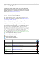
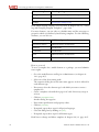
The following overview shows the structure of configuration, the respective
menu items in the model browser, information about the corresponding
section in the user manual and in the Innovator classiX editions.
The order the overview is in represents that of the group box Option
groups in the dialog box Configuration/Load Model Options
(see A-2.3, "Loading Model Options", page A-31).
Innovator Business edition classiX
Innovator Object edition classiX
Innovator Data edition classiX
Innovator Function edition classiX
Option Group
Settings under
Model>Configuration>
Options
General Settings see A-2.2.2
Fonts
Element Fonts see A-2.2.3
Object colors
Element Colors see A-2.2.4
Structure templates
Model Structure see A-3.3
Structure templates
Model Structure see D-7
Labels
Labels see A-2.2.5
Copyright © 2010 MID GmbH
21
A-2 Opening and Configuring Models
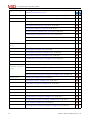
Option Group
Settings under
Model>Configuration>
Texts
Specifications and External Objects see C-2.4.2
Object types
Specifications and External Objects see C-2.5.1
Filter
Packages>Selection Filters see A-4.2.1
Classes>Selection Filters see A-4.2.1
Classes>Display Filter see A-4.2.2
Constraints>Selection Filters see A-4.2.1
Components>Selection Filters see A-4.2.1
Components>Display Filters see A-4.2.2
Objects>Selection Filters see A-4.2.1
Element Properties see A-4.1
Packages>Properties see A-3.4
Packages>Diagram Properties see A-4.3.6
Classes>Diagram Properties see A-4.3.7
Components>Diagram Properties see A-4.3.7
Use Cases>Diagram Properties see A-4.3.6
Continue
Objects>Diagram Properties see A-4.3.6
Element properties
Interactions>Diagram Properties see A-4.3.6
States/Activities>Diagram Properties see A-4.3.6
Tailoring/Analysis>Diagram Properties see A-4.3.6
Packages>Templates see A-4.3.2
Classes>Class Templates see A-4.3.2
Classes>Diagram Templates see A-4.3.5
Classes>Relationship Templates see A-4.3.3
Constraints>Templates see A-4.3.2
Components>Component Templates see A-4.3.2
Components>Diagram Templates see A-4.3.5
Components>Relationship Templates see A-4.3.3
Use Cases>Templates see A-4.3.2
States/Activities>Diagram Templates see A-4.3.5
Element properties
Templates
22
Manual classiX A Models Innovator 11
A-2.2.2 General Settings
Option Group
Settings under
Model>Configuration>
Classes>Display Templates see A-4.3.4
Constraints>Display Templates see A-4.3.4
Components>Display Templates see A-4.3.4
Engineering actions
Engineering>Actions
Verifications
Verification Routines see A-5
Wraps
..>Word Wraps see B-2.4.2
Process analyses
Process Analyses see D-6.3.2
Class display
A-2.2.2
Engineering
General Settings
As model administrator, you can make general settings for the model in the
model browser via Model>Configuration>General Settings....
The configurations can only be changed if the user is logged-in as administrator. If this is not the case, the user has read-only access only, i.e.
the elements in the dialog which the modifications effect are inactive.
Note
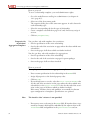
The dialog box Configuration/General Settings contains various
tabs with option groups and individual settings. The following overview
lists the tabs and option groups, as well as where they are in the Innovator
editions.
Tabs
Groups
Wraps
Implementation
SA/SD: Language; COBOL; File restrictions; File extensions; C
BPM: File restrictions
Namespaces
BPM: Prevent duplicate names; Default for namespace dialog
Dialog Settings
BPM: Classes, attributes and methods; Constraint
Copyright © 2010 MID GmbH
23
A-2 Opening and Configuring Models
Tabs
Groups
Display Options
Activity numbering; Control flow; Kurznamen;
Tailoring
Views
Views
SA
Process numbering; SA constraints; Diagram numbering; Environmental flows
The following section will explain the setting options for the individual
model types in more detail.
Spanning all Model
Types
Attention
Tabs Wraps
Innovator manages global and model-specific specifications for wrapping
element names for displaying in diagrams or tables (see B-2.4, "Wrapping
Names of Elements", page B-55).
The model-specific specification in the Wraps tab comes into effect if the
other specifications are not sufficient.
Changes to settings affect the layout of the element in all interfaces.
• Maximum Length field
If required, a word can be split (wrapped) after the number of characters
is entered.
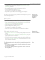
SA/SD Model
Tabs SA
You can set the type of process numbering in SA diagrams in the Process
numbering tab:
• Short
The processes of a hierarchy level are serially numbered in sequence.
• Long
The processes contain a multi-digit number; the respective parent processes can be read off these. The number indicates a path component
from the process of the highest hierarchy level to the process considered.
The number of processes in context or flow diagrams cab be restricted in
the SA Constraints group.
• CD processes
The number determines the maximum permissible number of processes
in the context diagram. You can enter values from 1 to 99.
• Processes
The number determines the maximum permissible number of processes
in the flow diagram. You can enter values from 1 to 99.
24
Manual classiX A Models Innovator 11
A-2.2.2 General Settings
• Terminator
The check box sets whether the terminators are enabled in other diagrams as the root diagram.
These constraints are tested when the verifications are run.
The display of environmental flows can be set in the Environmental
Flows group:
• Show origin
If the Show Origin check box is activated, the environmental flows in
the SA diagram are shown with the name and type of the linked elements from the parent diagram.
The display of the numbering of SA diagrams can be set in the Diagram
Numbering group:
• Show
If the Show check box is activated, the diagram number is shown in the
SA diagram's info box.
Tabs Views
You can determine the data model which is assigned to the model in the
Views group:
• Repository
The name of the repository which contains the data model. If this field is
left empty, then the repository which also contains the current SA model
will be adopted.
• Model
The name of the data model.
If the server is running with the data model, then the repository and
the model can be selected from the lists.
Note
• Data elements in the data dictionary
The respective data dictionary entries are shown for the suggested type
definitions when the check box is activated.
Tab Implementation
You can determine the model's implementation connection in the Language group. Depending on the language selected, if applicable, a special
group is activated for language-specific settings.
• Language
You can select a target language for the design out of the languages offered.
• Types to code
If the check box is activated, the type declarations from the data dictionary are generated in the header files as program text rather than comments. The include instructions of these header files also appear in the
module and are not just noted as comments. The type declarations are
Copyright © 2010 MID GmbH
25
A-2 Opening and Configuring Models
explicitly entered in the linkage or working storage section or using the
COBOL copybook for the target language COBOL and not as a comment.
• Interfaces to code
If the check box is activated, technical interfaces from the SD are generated as program text rather than comments.
You can determine the file extensions for include and source files in the
File Extensions group.
If you have selected COBOL as your language, then you can make settings
for generating copybooks in implementation modules in the COBOL group.
• Copybook prefix
The string (which can be a maximum of 7 characters long) determines
the prefix given to every data field name within a copybook. Within the
working storage or linkage section, this prefix is replaced by the parameter name when the COPY command is selected.
• COPY generation
If the check box is activated, copy commands are used in the linkage or
working storage section instead of explicit type declarations.
• Copybook quotes
If the check box is activated, the name of the copybook is generated for
the COPY command in quotes.
If you have selected C as your language, then you can make settings for
generating comments and program text in implementation modules and
header files in the C group:
• Main prefix
If more than one program needs to be maintained in a model, then the
main functions in SD need to have different names.
All functions which have the appointed prefix will be generated as main
in the implementation.
• Typedef suffix
As is the case with most C compilers, you cannot have the same value for
type and name during type definition. This means a postfix can be specified for type generation for data dictionary types, e. g.:
With the entry '_',
typedef struct {
a a;
}
goes to
typedef struct {
a a_;
}
26
Manual classiX A Models Innovator 11
A-2.2.2 General Settings
• Exploded types
If the check box is activated, the comments created upon generation of
type definitions for DD entries in header files also contains type definitions for all referenced data dictionary entries from the corresponding
data dictionary entry.
• Forwards to code
If the check box is activated, forward declarations are generated as program text rather than comments (only for C).
You can set the significant name lengths of modules in the File Restrictions group. Modules with a longer name can be easily created. If
two module names start with the same characters and these have a larger or
the same value, then a verification message appears. Values between 8 and
99 can be used for the name length.
• Case sensitive
If the check box is activated, comparison between module names is case
sensitive.
• Lifelink
If the check box is activated, after editing of an implementation has taken place and the data is being saved, the corresponding data in the Lifelink directory is also updated in the repository.
Tabs Dialog Settings
You can set defaults for options with the same name in the corresponding
property dialogs.
Tabs Implementation
You can set the significant file name lengths of modules and take case sensitivity into account when comparing module names in the File Restrictions group.
• File name length
Enter the significant file name length of the modules. Modules with a
longer name can be easily created. If two module names start with the
same characters and these have a larger or the same value, then a verification message appears. Values between 8 and 99 can be used for the name
length.
• Allow case sensitivity
If the check box is activated, comparison between module names is case
sensitive.
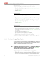
The Allow Multiple Reservation check box specifies whether
components of more than one user can be reserved for making changes at
the same time.
Tabs Namespaces
You can find more information about the use of namespaces in Innovator
in chapter B-2.6, "Reducing File Path Components Using Namespaces",
page B-64.
Copyright © 2010 MID GmbH
BP Model
27
A-2 Opening and Configuring Models
You can set the scope of names in the Names Unique group. The activated In Package radio button enables the use of namespaces, the In
Model radio button turns this function off.
In the Prevent Duplicate Names group, you can specify whether a
warning should appear if a name for one element of the same type is duplicated and what under prerequisites this should occur. The setting concerning the use of namespaces, needless to say, has precedence.
Completely qualified names are only resolved in toplevel packages which
are integrated into the toplevel package of referenced elements through an
explicit modeled resolve dependency. The Resolve Names in Referencing Toplevel Tree check box additionally uses all toplevel
packages from the system of the referenced elements for breaking down the
name.
You can select the default for the options in the namespace dialog in the
Default for Namespace Dialog group. However, these only apply
to those commands for which you cannot a pick a sensible pre-allocation
of options from the task.
Tabs Display Options
You can set the type of activity numbering in the Activity Numbering
group:
• Short
The number is made up of the package's shortname and a hierarchical
number. Respective part activities of a package contain an addition consecutive number.
• Long
The activities contain the same numbering as with the Short option. If
an activity is used again in another position as its definition position,
both hierarchical numbers are shown.
If you activate the Show Control Flow check box in the Control
Flow group, the control flow's transitions are shown in bold in the activity
and activity definition diagrams.
You can determine how shortnames of activities are displayed in the
Shortnames group. If the check box is activated, then the package's
shortname and the number of the activity are formed, otherwise the shortname entered by the user is shown.
You specify whether elements affected by tailoring in activity and activity
definition diagrams should be shown in the color for the secondary element in the Tailoring group. Otherwise the elements cannot be seen in
a non-locked state.
28
Manual classiX A Models Innovator 11
A-2.2.3 Element Fonts
A-2.2.3
Element Fonts
As model administrator, you can configure individual fonts for each editor
type (diagrams, tables) in the model browser under Model>Configuration>Element Fonts.... Each editor type has its own tab which always has the same drop-down lists.
The configurations can only be changed if the user is logged-in as administrator. If this is not the case, the user has read-only access only, i.e.
the elements in the dialog which the modifications effect are inactive.
Note
The Elements drop-down list lists all elements of the editor type selected
with the tab. The font assigned to each selected element is shown in the
Fonts drop-down list.
Selecting a font from the Fonts drop-down list affects the allocation of
this font to the selected element in the Elements drop-down list.
The font is shown in the display area at the bottom and to the right.
The fonts set are used as default in the corresponding editors for editing
newly-created elements.
If the fonts should also apply to diagrams, tables etc. which already exist,
then you need to explicitly transfer them into the respective editor in the
Diagram|Table/Layout/Fonts dialog by clicking on the [Default] button.
A-2.2.4
Element Colors
As model administrator, you can configure individual element colors for
each editor type (diagrams, tables) in the model browser under Model>
Configuration>Element Colors.... Each editor type has its own
tab which always has the same drop-down lists.
The configurations can only be changed if the user is logged-in as administrator. If this is not the case, the user has read-only access only, i.e.
the elements in the dialog which the modifications effect are inactive.
Note
The Elements drop-down list lists all elements of the editor type selected
with the tab. The color assigned to each selected element is shown in the
Colors drop-down list.
Selecting a color from the Colors drop-down list affects the allocation of
this font to the selected element in the Elements drop-down list.
The color is shown in the display area at the bottom and to the right. Due
to the screen options, if applicable, various colors from the drop-down list
are displayed in the same tone.
Copyright © 2010 MID GmbH
29
A-2 Opening and Configuring Models
The colors set are used as default in the corresponding editors for editing
newly-created elements.
These pre-defined colors do not have to be explicitly transferred in diagrams or tables for elements which already exist.
A-2.2.5
Labels
As model administrator, you can configure labels under Model>Configuration>Labels... in the model browser. Configuring Labels for the
Model In the dialog of the same name, define the labels for the model generally or for certain element types in the Labels tab and the corresponding values for the labels in the Values tab.
Note
The configurations can only be changed if the user is logged-in as administrator. If this is not the case, the user has read-only access only, i.e.
the elements in the dialog which the modifications effect are inactive.
Labels are not language-dependent and (unlike element properties) can be
generally set for all element or document types.
Labels can be referenced in specification texts. A typical label is the editing
status.
Labels tab
The Element Type list contains all element types of the model which
can be assigned labels. The General element type applies for all these elements.
After selecting a type, its label is shown in the Labels list.
You can add a named label to this list with the Name field with the [Add]
button. You can activate a change for the selected label from the Property group with the [Change] button. The [Delete] button deletes
the selected label from the list.
You can change the order of the labels using the [Up] or [Down] buttons.
This order is taken into consideration in the labeling elements of diagrams,
tables and trees, as well as in documentation.
The name of a selected label is transferred to the Name field. If required,
you can make changes here.
You can enter a value as a default for the label in the Default Value
drop-down list. You can only make a selection from the defined value
range for fixed values. In this case, the default value is first given if the values were configured.
A label with the Strings or Numeric type can be assigned to any strings
or to numeric. For labels with the Fixed Values type, only predefined
values which were defined in the Values tab are permissible.
If the Visible in GUI and Docu check box is deactivated, a label
will be suppressed in this position.
30
Manual classiX A Models Innovator 11
A-2.3 Loading Model Options
Values tab
The Element Type list contains the element types which you assigned.
After selecting a type, its label is shown in the Labels list.
The values of a selected label are listed in the Values list. A value selected
there is transferred to the Name field, where it can be modified.
In various editors, you can specify the colors of element texts by selecting a
label or tagged value via Extras>Options... If the label selected there
or correspondingly the tagged value are defined for an element, then its
text is shown in the color which was assigned to their current value in the
Color drop-down list.
Colors can be set for intervals for numeric labels. Values with an interval of
two numerics are separated by a comma and this value is assigned a color.
You can change the order of the values using the [Up] or [Down] buttons. This order is taken into consideration when searching for labels and
in documentation.
A-2.3
Loading Model Options
If you enter a configuration file when creating a new model, your model already contains a basic configuration of various settings. However, you can
also load this any time at a later date. To do this, set which settings should
be transferred to the current model, as well as whether the available data
should be overwritten or not.
How to proceed
To load a configuration file at a later date:
» Go to the model browser and log-in as administrator (see page A-5).
» In the model browser, select Model>Configuration>Load Model
Options....
The dialog box of the same name appears.
» Choose which model option you want to load with the Basis or AddOn radio buttons.
» Select a file from the Configuration File drop-down list.
All check boxes are activated for settings by default.
» To deactivate all check boxes at the same time, click on [Uncheck Options].
» Set which settings you want to import into the current model via check
box in the Load column in the Option Groups
» If you want to overwrite settings of the current model, activate each corresponding check box in the Replace column.
Copyright © 2010 MID GmbH
31
A-2 Opening and Configuring Models
» Click on the [Apply] button.
The configuration file is loaded.
» Close the dialog box with [Close].
A-2.4
Saving Model Options
The following settings are saved:
• General settings: Settings for the project language, implementation,
namespaces and word-wraps, diagram displays (Innovator Data edition),
views (Innovator Data edition)
• Method-based fonts and object colors
• Labels and label values
• Specification types: Templates for element specifications (see page C-27)
• External objects: Settings for Tcl scripts which manage external programs (see page C-32)
• Structure templates: Predefined package structures which are made available for the current model (see page A-56)
• Selection and display filters: Filters which are stored for packages and
other element types
• Element properties: Stereotype values and other properties which are
stored for element types.
Note
If element properties are needed for other settings (e.g. filters), they are
automatically imported to ensure consistency.
•
•
•
•
Templates: Standard defaults for creating new model elements
Engineering actions
Verification routines: Combination of verification routines
further settings for the respective model type
How to proceed
To save settings for configuration in a file:
» Go to the model browser and log-in as administrator (see page A-5).
» In the model browser, select Model>Configuration>Save Model
Options....
The dialog box of the same name appears.
» If you want to save an add-on model option, activate the Save as
Add-On check box.
32
Manual classiX A Models Innovator 11
A-2.4 Saving Model Options
» Enter a significant name in the Configuration File field or select
one from the drop-down list.
» Close the dialog box by clicking on [OK].
If the file already exists you will get a corresponding message.
» Click on [OK] to overwrite the file or click on [Cancel] and enter another name.
The settings are saved in the file.
Copyright © 2010 MID GmbH
33
A-3 Structuring Models with Packages
You can structure your model by grouping its elements according to certain
criteria and combining them in a package. You can specify the criteria according to which you structure your model as desired. This means that you
can e.g. sort elements according to their type, thereby combining all of a
type's diagrams in one package. If you already want to display your model's
architecture, you can also set up a package for various components from
your system. Of course, any combinations of these approaches are also possible.
If you want to create source code files from your model data in forward engineering, the packages which contain the elements for implementation are
used a directory names. This happens the other way round for reverse engineering, so that packages are created from directory names which contain
source code files.
The packages in Innovator can be extensively configured. You can set yourself which packages should have what meaning and where, which elements
they comprise and which properties they have. This enables you the highest degree of freedom when structuring your model.
With regard to their use, packages can be split into different categories. A
few examples:
• System models: («systemModel» package type) They include an entire
model which is consistent in itself. As many other packages as required
can be included under it. System models are normally located directly
under the root package. As default, they contain the "Administrator
package" property; this means that you need administrator rights to be
able to create, modify or delete.
• Packages with model elements: You can configure, create and modify
these packages yourself as and when required. They contain various elements from your model.
• Address packages: If you want to display directory structures which exist outside of Innovator in your model, enter an address package which
the desired directory is associated with. This subdirectory can then be
displayed as a son package under this address package. This enables you
to exchange data between the file system and the model.
Copyright © 2010 MID GmbH
Use of Packages
35
A-3 Structuring Models with Packages
A-3.1
Note
If you create a new model, you can base it on a pre-configured structure
template or import it at a later time. Each of these structure templates
provided already contains a complete package structure (see chapter A3.3, "Creating Package Structures", page A-53).
Properties of a
Package
When working with packages, the following properties must be taken into
consideration/you must include the following packages:
• Container for elements: Each element in Innovator is stored in a package. The element is identified by its package path (the name of its parent
package), its name and its element type.
• Hierarchical structure: Packages can be divided hierarchically. Each
package can contain as many other packages as required.
The top-most package of a model–the so-called root package– is available automatically. It contains the name of the current model. It cannot
be deleted.
• Namespace: In methods which support package-local namespaces
(Innovator Business edition), a package forms a closed namespace (see
chapter B-2.6, "Reducing File Path Components Using Namespaces",
page B-64). References to elements outside out this namespace need to
be created via special mechanisms (e.g. path components or dependencies).
• Package names: Each package has one name. This name must be
unique within the higher-level package.
• Package types: You can predefine various package types with certain
properties. This enables you to e.g. set which elements are permissible
within a package of this type.
• Relationships between packages: You can display the relationships between the packages in a package diagram.
Working with Packages
You can manage packages in the model browser. You can verify and edit
the structure of the package tree at any time in the model browser's model
tree.
You can create, change, delete, copy and insert packages. You can refine
packages using son packages; you can also move them into other parent
packages and assign them a stereotype and, through this, certain properties.
As the basic structure of the entire model is set using packages, at least the
majority of the package structure's top-most levels are designed using the
model administrator. This means that package structures can be imported
from pre-configured configurations or generated from certain properties
(see chapter A-3.3, "Creating Package Structures", page A-53).
36
Manual classiX A Models Innovator 11
A-3.1.1 Creating and Changing Packages
Using packages you can e.g. roughly define responsibilities, assign access restrictions to individual packages, organize rules about visibility between
packages.
The following chapter deals with how you work with packages in the
model browser.
• chapter A-3.3, "Creating Package Structures", page A-53
• chapter A-3.4, "Making Specifications to Packages", page A-60
• chapter A-4.3.2, "Creating Packages for Model Elements and Packages",
page A-91
• chapter A-3.2, "Modeling Dependencies Between Packages in Package
Diagrams", page A-45
• chapter B-1.3.3, "Changing the Order of Entries", page B-10
• chapter B-2.6, "Reducing File Path Components Using Namespaces",
page B-64
• chapter A-3.4.2, "Creating New Stereotypes and Properties for Packages", page A-64
• chapter A-3.4.3, "Creating Filters for Son Packages", page A-67
A-3.1.1
Other Information
Creating and Changing Packages
If you create a new model, you can base it on a pre-configured configuration. This means that your new model will already contain the package
structure from the configuration. You can also import or generate package
structures at a later date (see chapter A-3.3, "Creating Package Structures",
page A-53). In this chapter you will learn how to create and change package individually.
The top-most package of a model is the so-called root package. It always
contains the model's name and cannot be deleted. You can create as many
packages as required in the root package.
You can create packages in the model browser or in a package diagram. In
this chapter you will learn how to create packages in the model browser.
To create a package, you can
• use a template as the basis
• assign a default set to properties, which is obtained from the son configuration
Templates can be stored for packages. All properties are stored in them.
The most important are:
Copyright © 2010 MID GmbH
Using Package
Templates
37
A-3 Structuring Models with Packages
• Address: If a package contains the Address property, then you can
deposit a directory on a computer. When reverse or forward engineering
takes place, a directory is created for this package in the file system (see
section "Displaying the Directory Structure from File Systems", page
A-40)
• topLevel: In Innovator editions which support package-local
namespaces, set the visibility limit of a namespace using this property
(see chapter B-2.6.5, "Defining Subtrees", page B-72).
• Stereotype: You can group packages according to certain properties
via stereotype. You can e.g. create filters or define permissible elements
using a package's stereotype value.
Read how to create package templates in chapter A-4.3.2, "Creating Packages for Model Elements and Packages", page A-91.
Creating Packages
When creating a package, the parent package cannot be locked by another
user.
Note
You can only create packages below the model's root package or any
packages from the «systemModel» stereotype if you have administrator
rights.
How to proceed
If you want to create a new package:
» Go to the model browser.
» If necessary, open the package structure's subtrees in the model tree.
» Select the package which you want to create a new package under.
Every package template which is already stored in the model is offered
as an individual entry in the Element>New>Package menu. In addition, you can also find the New entry here. You naturally create a package which has a default set of properties. These are calculated from the
settings which are stored in the son configuration (see page A-63) as
well as the element properties' standard values (see page A-65).
Note
You can only use package templates in packages in which son packages
with the template's properties are permissible.
» To create a package in accordance with the son configuration's settings,
select Element>New>Package>New.
» To create a package from a template, select Element>New>Package>
<Template>.
An empty package is created under the selected parent package. It has a
default name or the name which was specified in the template. If the
name already exists in the selected package, then it will be made unique.
38
Manual classiX A Models Innovator 11
A-3.1.1 Creating and Changing Packages
Read how to rename a package in section "Renaming Elements–General",
page B-50.
Upon creation, the package gets a stereotype which is set in the template
used or–if created without a template–in the son configuration of the parent package. You can change this default at a later stage.
Changing Stereotypes
The root package always has the stereotype value «innovator model».
You cannot alter this stereotype.
In addition, the package stereotype can only modify values which are
also permissible according to the parent package's configuration.
Note
How to proceed
To change the stereotype of an individual package:
» Go to the model browser.
» If necessary, open the package structure's subtrees in the model tree.
» Select the package whose stereotype you want to modify and lock it as
well.
» Select Element>Properties....
The dialog box of the same name appears.
» If necessary, select the Element Properties tab.
You can show the less important package types in the Element Properties group with the Show All check box (see page A-65). All
properties are shown in the Name column.
» Select the Stereotype entry in the Name column.
The current package's stereotype value is shown in the Value column.
» Select the stereotype value in the Value column which you want to assign to the package.
» Close the dialog box by clicking on [OK].
The stereotype is changed. The stereotype icon is displayed in the package.
How to proceed
To change the stereotype of several packages at the same time:
» Go to the model browser.
» If necessary, open the package structure's subtrees in the model tree.
» Select the packages whose stereotype you want to modify and lock it as
well.
» Select Element>Properties....
The dialog box of the same name appears.
Copyright © 2010 MID GmbH
39
A-3 Structuring Models with Packages
» Select the Stereotype entry in the Name drop-down list.
» Select the stereotype value in the Value drop-down list which you want
to assign to all selected packages.
» If you want to modify further stereotypes, click on [Apply]. Otherwise, close the dialog box with [OK].
The stereotype is changed. The stereotype icon is displayed in the package.
Displaying the
Directory Structure
from File Systems
You can display the directory structure for source code files using packages.
You need these if you want to generate source codes from your model data
or –vice versa–if you want to generate model data from an available source
code using reverse engineering.
You can provide any package with an additional property–the Address
property– and then deposit the required directory path component in the
file system Such packages are referred to as address packages.
Note
Users who have already worked with older versions of Innovator will
know this subtree as a Lifelink path component.
You can enter three different path components as the source code files' root
for every address package which should be displayed in the directory structure:
• on the current local computer under your login
• on any computer under your login
• for all users of the model
Note
You need administrator rights to modify the directory structure for a
package for all users.
How to proceed
To assign the address property to a package:
» Go to the model browser. If you want to carry out the setting for all users, log-in as administrator (see chapter A-1.2.1, page A-5).
» If necessary, create a new package. If the package already exists, lock it.
» Select Element>Properties....
The dialog box of the same name appears.
» Select the Element Properties tab.
» Select the Address entry in the Name column and select the yes entry
in the Value column.
The Address tab is activated.
» Select the Address tab.
40
Manual classiX A Models Innovator 11
A-3.1.2 Copying and Moving Packages
» Set an alternative in the Settings for group.
» In the Address field, enter the path component under which the directory structure should be created at a later date or click on [Select...] and select a directory.
» Click on [Apply].
» If necessary, repeat this action with the other junctions in the Settings for group.
» Finally, close the dialog box with [OK].
You can represent the packages which are defined as addresses in the model
browser by displaying the associated directory path component.
Activating and
Deactivating the
Directory in the Model
Browser
How to proceed
To show the directory path component of address packages in the model
browser:
» Go to the model browser and select Extras>Options....
The dialog box of the same name appears.
» Activate the Show Address check box in the General tab.
» Close the dialog box with [OK].
» Click on [Apply] and close the dialog box with [Close].
The associated directory path components are shown in the model tree
next to the packages which are defined as address packages. The path
component which is set for the login and computer combination is
shown next to the address packages (see page A-40).
A-3.1.2
Copying and Moving Packages
You can copy a package with all of its properties. This adjusts the package's
name if a package with the original name already exists in the new parent
package.
Elements and son packages in a package are not transferred in the copy.
Note
You can also move a package within the model by entering another package as the parent package. In this case, all elements and son packages will
also be moved with the package.
To copy a package, neither the package you want to copy, nor the package
under which you want to insert the copy need to be locked. However, the
latter cannot be locked by another user.
Copyright © 2010 MID GmbH
Copying packages
41
A-3 Structuring Models with Packages
How to proceed
To copy a package:
»
»
»
»
»
Go to the model browser.
If necessary, open the package structure's subtrees in the model tree.
Select the package you want to copy.
Select Edit>Copy.
Select the package you want to insert a copy under and select Edit>
Paste>As New Element.
The package is inserted under the selected package. The copy is locked.
If necessary, the name is changed to maintain uniqueness.
Moving Packages
You can move packages within the model. Unlike when copying, all elements and son packages are moved; the structure is retained in the package
affected. References to elements within the moved package are adapted.
Note
The name of the package is not adapted when moved. If a package with
the same name already exists in the new parent package, you will not be
able to execute the move.
You have two options when moving a package:
A: Moving using drag-and-drop
B: Moving via the menu
How to proceed
To move a package using drag-and-drop:
» Go to the model browser.
» If necessary, open the package structure's subtrees in the model tree to
make the package which is to be moved and the desired parent package
visible.
» Select the package which you want to move and lock it.
» Move the selected package into the desired parent package.
If a package with the same name does not already exist in the new parent package and if the package type is permissible as a son, then the
package is moved into the new parent package. Otherwise you will get
a message.
42
Manual classiX A Models Innovator 11
A-3.1.3 Modifying the Hierarchy of Packages
How to proceed
To move a package via the menu:
»
»
»
»
Go to the model browser.
If necessary, open the package structure's subtrees in the model tree.
Select the package which you want to move and lock it.
Select Edit>Move to....
The dialog box of the same name appears.
» If the desired parent package is displayed, select it. Otherwise deactivate
the check boxes.
The packages which were not visible due to the filter are now displayed.
» If necessary, open the subtrees and select the new parent package.
If a package with the same name does not already exist in the new parent package and if the package type is permissible as a son, then the
[OK] button is activated.
» Click on [OK].
The package is moved to the new parent package.
A-3.1.3
Modifying the Hierarchy of Packages
Packages are hierarchically divided, i.e. each package gives a detailed view
of a higher-level package. In this chapter you will learn how to
• insert a further hierarchy level between the current package and its parent package.
• resolve a hierarchy level by moving all of a package's elements into its
parent package and thereby delete the package.
You can find the menu items for inserting and resolving hierarchy levels in the package diagram as well as in the model browser.
Note
You can insert a new package between a package and its parent package
and, in doing so, add a hierarchy level.
Inserting Hierarchy
Levels
You cannot insert a hierarchy level before the model's root package.
Note
The effect is the same as if you are creating a new package within the parent package and moving the selected package into the new package.
You can insert a hierarchy level in front of various packages at the same
time, as long as all of the packages are in the same parent package.
Copyright © 2010 MID GmbH
43
A-3 Structuring Models with Packages
How to proceed
To insert a hierarchy level:
» Go to the model browser.
» If necessary, open the package structure's subtrees in the model tree.
» Select the packages (in the same parent package) you want to insert a
new hierarchy level above and lock them as well.
» Select Edit>Package Hierarchy>Create Level.
A new package is inserted above the selected package. The new package
has a default name and the stereotype from the son configuration.
Read how to rename a package on page B-50.
Resolving Hierarchy
Levels
If you resolve a hierarchy level, all elements and son packages on this level
are moved to the parent package above and the existing package is deleted.
Note
If elements of the same type with the same name exist in the package's
parent package which you want to resolve, a name clash occurs when
resolving. In this case, the procedure is canceled and an error message
occurs.
Note
You cannot resolve the model's root package.
How to proceed
To resolve a hierarchy level:
»
»
»
»
A-3.1.4
Go to the model browser.
If necessary, open the package structure's subtrees in the model tree.
Select the package you want to resolve.
Select Edit>Package Hierarchy>Resolve Level.
The package is deleted, all elements and son packages are moved one
level higher.
Deleting Packages
You can delete packages. This also deletes it from the model. This action
deletes the entire contents, i.e. all elements and son packages contained
within the package, as well their contents recursively.
Read how to remove a package from the structure without deleting the son
package in chapter A-3.1.3, "Modifying the Hierarchy of Packages", page
A-43.
44
Manual classiX A Models Innovator 11
A-3.2 Modeling Dependencies Between Packages in Package Diagrams
How to proceed
To delete a package in the model browser:
» Go to the model browser.
» If necessary, open the package structure's subtrees in the left-hand area of
the model browser.
» Select the package you want to delete. Ensure that the package and all of
this package's elements–i.e. also in its son packages– are locked.
You can transfer all elements of a subtree in the result area of the model
browser and lock them there at the same time. Read about this in
chapter B-3.2, "Searching for Elements", page B-82.
Note
» Select Edit>Delete.
If the deletion control is turned on, the dialog box of the same name appears. All elements which are listed are deleted by the action.
» Check whether you really want to delete the elements. If necessary, cancel the procedure with [Cancel].
» Otherwise, close the dialog box with [OK].
The package and all of the elements within it are deleted.
A-3.2
Modeling Dependencies Between Packages in Package Diagrams
When you are maintaining the hierarchical structure of the package in the
model browser, set which dependencies should exist between packages in
the package diagram.
You can model the following dependencies between packages in the package diagram:
• Maintain dependency (see page A-48)
• Access dependency (only in Innovator Business) (see page A-48))
• Import dependency (only in Innovator Business) (see page A-48))
• Resolve dependency (only in Innovator Business) (see page A-49))
• Any other stereotypes for dependencies which are preconfigured in the
configuration or were inserted at a later date (see chapter A-4.1, "Defining Stereotypes and Properties of Elements", page A-75).
A-3.2.1
Creating and Opening Package Diagrams
You can create a package diagram in the model browser.
Copyright © 2010 MID GmbH
45
A-3 Structuring Models with Packages
Using Diagram
Templates
Creating Package
Diagrams
Templates can be stored for package diagrams. The stereotype of the package diagram is stored in it. In turn, you can e.g. define a icon which will be
displayed in the model browser next to the package diagram using these.
Read how to create diagram templates in chapter A-4.3.5, page A-99.
You can create a package diagram in the model browser.
How to proceed
To create a package diagram:
» Go to the model browser.
» If necessary, open the package structure's subtrees in the left-hand area of
the model browser.
» Select the package which you want to create a package diagram in.
Every package diagram template which is already stored in the model is
offered as an individual entry in the Element>New Diagram>Package Diagram menu. In addition, you can also find the New entry
here. Furthermore, you create a package diagram which has a default set
of properties.
» To create a package diagram with default properties, select Element>
New Diagram>Package Diagram>New.
» To create a package from a template, select Element>New Diagram>
Package Diagram><Template>.
The package diagram is shown in the list of model elements.
» To open the package diagram, select it if necessary and select Element>
Open.
The package diagram opens. You can create packages, display (add)
packages which already exist and display relationships between packages
in package diagrams.
A-3.2.2
Creating and Adding Package Diagrams
You can create packages in the model browser or in a package diagram. In
this chapter you will learn how to create packages in package diagrams.
If you create a package in a package diagram, you create a son package as
default in the package in which the package diagram is also located. If you
add a package, consider certain relationships which it has to other packages
in the current package diagram (see chapter B-2.1.2, "Logical and Graphic
Existences of Model Elements", page B-22). In this way, you can display a
package in as many package diagrams as required. However, you can only
display each package once in a package diagram.
To create a package, you can
• use a template as the basis (see page A-37)
46
Manual classiX A Models Innovator 11
A-3.2.2 Creating and Adding Package Diagrams
• assign a default set to properties, which is obtained from the son configuration
Read how to create package templates in chapter A-4.3.2, "Creating Packages for Model Elements and Packages", page A-91.
If you create a package in a package diagram, you create it as a son package
as default in the current package (as long as no redirection is configured for
is, see page A-68). To assign it to another parent package, you subsequently
need to move it there (see page A-42).
You can use templates for packages. Read about which properties are stored
in package templates in section "Using Package Templates", page A-37.
Creating Packages
How to proceed
To create a package in a package diagram:
» Jump to the package diagram and lock it if necessary.
Every package template which is already stored in the model is offered
as an individual entry in the Insert>Package menu. You can also
find the New entry here. You create a package which has a default set of
properties using these.
» To create a package with default properties, select Insert>Package>
New.
» To create a package from a template, select Insert>Package><Template>.
The package is created and displayed in the diagram. It has a default
name or the name and the properties which were specified in the template.
If you want to assign the package to another parent package at a later
date, the package remains in the diagram, but only as one of many possible representations.
Note
If a package already exists, you can add it to every package diagram which
does not already have it.
Adding Packages
How to proceed
To add a package in a package diagram:
» Jump to the package diagram and lock it if necessary.
» Select Insert>Package>Add existing....
The dialog box of the same name appears. The part of the package tree
which leads to the current package is shown in the Namespaces
group.
Copyright © 2010 MID GmbH
47
A-3 Structuring Models with Packages
» If the desired package is displayed in the Namespaces group, select it.
Otherwise deactivate the check boxes in the Namespaces group.
The packages which were not visible due to the filter are now displayed.
» If necessary, open the subtrees, select the package and click on [Add].
» In this way, specify all packages which you want to display in the package diagram.
» Click on [OK].
The package/s are added to the package diagram.
A-3.2.3
Producing Relationships Between Packages
The communication between elements of various packages should take
place via set channels. This makes it easy to verify which effects the modifications which you set for a package's elements could have on elements of
another package. Maintenance, in particular troubleshooting in your system, works in a targeted way alongside dependencies of the packages concerned. Correspondingly, the dependencies between the packages should be
reduced to a necessary minimum.
Innovator offers the following dependencies between packages as standard:
Maintain Dependency
You can adjust dependencies between packages with relationships between
their elements. Relationships which are incorporated by this acquire the
stereotype «maintain». Dependencies from this stereotype are maintained
by the system, i.e. created if necessary or deleted if they are no longer valid
(see page A-50).
Access Dependency
(only in Innovator Business)
You can restrict the contents of the drop-down lists using these dependencies. Only elements whose packages can be reached via the Access dependency are shown in the drop-down lists. The Access dependency has an effect if e.g. you want to add an element to a diagram which is not in the
same package as the diagram itself.
Note
In the Innovator Business edition, a missing Access dependency can be
ignored if you activate the With «access» Dependency Only
check box when adding an element.
Import Dependency
(only in Innovator Business)
Only use this dependency if you are working with namespaces. It enables
elements of another package to be imported in the own namespace as if it
was defined here. This means that you can omit file paths for references.
Read about file paths in chapter B-2.6.2, "Differentiating between File
Paths", page B-67.
48
Manual classiX A Models Innovator 11
A-3.2.3 Producing Relationships Between Packages
(only in Innovator Business)
This dependency is a prerequisite, so that types defined in the configuration or metamodel can be used for objects in the model. In addition, use
this dependency if you are working with package paths. This ensures that
precisely those file paths which could potentially exist in various subtrees
and which are specified by a Resolve dependency are used. In doing this,
you configure a package-local namespace. Read about toplevel packages in
chapter B-2.6.5, "Defining Subtrees", page B-72.
You can provide further dependencies between packages for your current model. For more information, read chapter A-4.1.1, "Expanding,
Modifying and Deleting Properties", page A-76.
Resolve Dependency
Templates can be stored for package dependencies. The dependency's stereotype and a default name are stored in them.
Read how to create dependency templates in chapter A-4.3.3, "Templates
for Relationships", page A-93.
Using Dependency
Templates
You can explicitly enter relationships between packages in the package diagram.
Manually Creating
Dependencies
How to proceed
To create dependencies between packages:
» Jump to the package diagram which you want to display the dependency
in and lock it if necessary.
» Display the packages which you want to produce the dependencies between by creating or adding them if required (see page A-46).
The order in which you select the packages determines which package
has access to which package. You can change this direction specification
afterwards.
» Select the package to be specified by the dependency.
» In addition, select the package to be referenced by the first one.
Every dependency template which is already stored in the model is offered as an individual entry in the Insert>Dependency menu. In
addition, you can also find the New entry here. Furthermore, you create
a dependency which has a default set of properties.
» To create a dependency with default properties, select Insert>Dependency>New....
» To create a dependency from a template, select Insert>Dependency><Template>.
A dashed arrow is shown between the packages. The arrow points towards the package whose elements are to be referenced.
Copyright © 2010 MID GmbH
49
A-3 Structuring Models with Packages
See Existing
Dependency
If dependencies are already modeled between packages in the model but
are not already displayed in the current package diagram, you can insert
them into the diagram. To do this, only one of the packages linked with
the dependency needs to already be displayed in the diagram. The missing
package is then automatically added.
Note
You can also naturally make existing dependencies for packages visible
using the maintenance settings (see chapter B-2.1.3, "Displaying Relationships to Model Elements from Other Diagrams (Maintenance Status)", page B-24). However, by doing this, you always acquire
• All linked packages (complete model maintenance)
• All dependencies in the diagram (maintenance local in the diagram)
On the other hand, when dependencies are added, you can display subsets from both.
How to proceed
To display targeted dependencies to a package in the diagram which are already modeled:
» If necessary, lock the package diagram.
» Select the package which you want to make the dependencies visible to.
If this package in the model has dependencies which are not yet displayed in the current diagram, the Insert>Dependency>Add existing... menu item is activated.
» Select Insert>Dependency>Add existing....
The dialog box of the same name appears. All dependencies which are
already available in the model but are not yet displayed in the current
model are listed in the Existing Dependencies group.
» Select the dependencies which you want to display in the current diagram and close the dialog box with [OK].
The missing packages and dependencies are added to the package diagram.
Displaying Existing
Element Relationships
If relationships already exist between elements of different packages, you
can make the package dependencies which result from these visible in a
package diagram at a later date.
How to proceed
To adjust relationships between elements from different packages to package levels:
» Jump to the desired package diagram and lock it.
50
Manual classiX A Models Innovator 11
A-3.2.3 Producing Relationships Between Packages
» Select Engineering>Adjust Dependencies.
If relationships between the elements from the diagram's packages are
already available in the model, they are also created between the packages and displayed in the current diagram. They acquire the stereotype
«maintain».
You can change package dependencies at a later time. The following changes are possible:
• Dependency direction
• Dependency name
• Dependency type
Changing
Dependencies
How to proceed
To change a dependency:
» If necessary, lock the package diagram.
» Select the dependency which you want to change and select Element>
Properties....
The dialog box of the same name appears.
You can enter the type of dependency via the stereotype.
Setting the
Dependency Type
The dependencies with the stereotypes «access», «import» and «resolve»
are only available in the Innovator Business edition.
Note
How to proceed
To set the type of dependency:
» Select the Element Properties tab in the Edit/Properties dialog box.
The current stereotype value is shown in the Element Properties
group.
You can activate the less important stereotype values in the Value column with the Show All check box (see page A-109).
» If required, activate the Display All check box.
Even the stereotype values of less importance will be activated.
» Select the entry in the Name column which you want to assign to the dependency to and click on [Apply].
Copyright © 2010 MID GmbH
51
A-3 Structuring Models with Packages
Changing the
Direction
When creating the dependency, you specified the direction through the order in which you selected the packages. You can reverse the direction at a
later time. You can also specify a bidirectional dependency or–in the
Innovator Data edition–a non directional dependency.
How to proceed
To change the dependency direction:
» Select the Direction tab in the Edit/Properties dialog box.
The junctions show the names of the currently selected packages. The
current direction–displayed in the first radio button,
from<Package1> to <Package2>–is activated.
» If you want to reverse the direction, activate the second radio button,
from <Package2> to <Package1>.
» If you want to enter a bidirectional relationship, activate the Bidirectional radio button.
» If you want to enter a non directional relationship–in the Innovator
Data edition –, activate the Nondirectional radio button.
» Click on [Apply].
Entering Names
Dependencies can have a name; this is, however, not mandatory. The
names of dependencies between two packages must be unique. This means
that no more than one dependency can have no name.
How to proceed
To define the relationship with a name:
» Select the Name tab in the Edit/Properties dialog box.
» Enter a name in the Name field. Ensure that this name does not already
exist for an existing dependency between the selected packages.
» Click on [Apply].
How to proceed
To close the dialog box:
» Finally, click on [OK].
52
Manual classiX A Models Innovator 11
A-3.2.4 Deleting Packages or Removing them from a Diagram
A-3.2.4
Deleting Packages or Removing them from a Diagram
Unlike in the model browser, you can add as many packages as required in
the diagram. This means that you can also only remove an added package
here. To do this, simply remove the package's special existences from the
diagram. The package itself remains in the model.
If however in contrast, you want to delete a package in the diagram, it will
be deleted from the model.
When a package is deleted, all of the elements within the package are also
deleted. Read how to remove a package from the structure without deleting
the son package in chapter A-3.1.3, "Modifying the Hierarchy of Packages", page A-43. You obviously also delete all relationships which the package has to other packages when you delete a package.
Deleting Packages
When a package is deleted from the diagram, your model's package structure remains unaffected. The relationships to this package which you are
displaying in the diagram are also removed from the diagram. However,
they are not removed from the model. If the same relationship is also displayed in other diagrams, these remain.
This procedure when removing or deleting packages is the same as the other procedures you are familiar with. Read about this in chapter B-2.5, page
B-61.
Deleting Packages
A-3.3
Creating Package Structures
If you create a new model, always base it on a pre-configured configuration–this uses a pre-existing package structure.
Learn how to configure a package structure from scratch in chapter A-3.1,
"Working with Packages", page A-36.
Basic models –structure templates– for each Innovator edition are already
included in the scope of delivery of Innovator. Each of these structure templates contains a suitable package structure, as well as a selection of diagrams and model elements which are used the most.
You can–also at a later date–import as many structure templates of an edition into your model as required and, in doing so, create the respective
packages contained (see page A-55). In addition, you can create a structure
template from a model yourself and make it available for other models
from the same edition (see page A-58).
Using Predefined
Package Structures
In this chapter you will learn how to
Copyright © 2010 MID GmbH
53
A-3 Structuring Models with Packages
• Automatically create a package structure (see page A-54)
• Export the package structure so that it can also be used in other models
(see page A-58)
• Transfer the package structure in the current model to another model
(see page A-55)
A-3.3.1
Automatically Creating Package Structures
Packages contain a special property: the stereotype. Among other things,
for each stereotype you can individually set the fact that this stereotype's
package can only contain certain son packages which contain a certain stereotype themselves. To do this, use a filter for permissible son packages (see
page A-112). In addition, you can set how many these son packages can respectively have (see chapter A-3.4.1, "Setting Permissible Elements", page
A-60).
Innovator can independently create a package structure from these specifications.
Example
You have set the fact that in each case the package from the «systemModel»
stereotype can only contain a son package from the «c++ implementation»
and «java implementation» stereotypes.
Innovator generates a «systemModel» package with the two son packages
«c++ implementation» and «java implementation» (also with the corresponding stereotypes) from this.
Constraint
The following constraints are created when package structures are automatically generated:
• If you permit the same stereotype for parent and son packages, no son
package is created (direct recursion)
• No more than one son package is created for each stereotype selected
within a package. If a son package already exists with this stereotype, the
path component will no longer be followed.
• Generating is automatically canceled after a maximum of eight levels.
• Indirect recursion is permissible, i.e. if you permit further son packages
(C) from a parent package (A) in a son package (B) which have the same
stereotype as the parent package (A). The packages are created as long as
no other stop criterion are met.
Generating Package
Structures
54
If you want to generate a package structure, the following prerequisites
must first be met:
• Selection filters are defined in models for package filters; these can be
used to access certain package stereotypes together (see page A-67).
Manual classiX A Models Innovator 11
A-3.3.2 Importing Package Structures
• The selection filters for packages are assigned as permissible son packages
for certain package stereotypes (see page A-60).
Both selection filters for packages and specifications for permissible
son packages can be transferred into the current model using configuration files (see chapter A-2, "Opening and Configuring Models", page
A-19).
Note
How to proceed
Innovator already provides all necessary selection filters (see page A-67). To
generate a package structure from the specifications to permissible son
packages:
» Select the package in the model tree in which you want to generate the
package structure. Ensure that it is not a package from the «systemModel» stereotype or the model's root package.
» Select Model>Create default Subpackages.
Depending on which stereotype the selected package has, all enabled
packages with their respective stereotypes are created under it.
A-3.3.2
Importing Package Structures
Special basic models (structure templates) are included in the scope of delivery of Innovator for each Innovator edition. Each of these structure templates contain a suitable package structure as well as elements (if applicable) in the packages. You can import as many structure templates of an edition into your model as required and, in doing so, create the respective
packages and elements contained (see page A-55).
Read how you can create a structure template from a model yourself and
make it available for other models from the same methods in chapter A3.3.3, "Exporting Structure Templates", page A-58.
You can store all specifications for the current model's configuration in
a configuration file and load them to another model (see chapter A-2,
"Opening and Configuring Models", page A-19). This means you can
select which configuration file's details you want to load–and the structure templates from these which are available in that model.
Note
To be able to import a structure template into your current model, the following prerequisites must be fulfilled:
• Structure templates for the current models are available ($INOPRJ/
config/template/[Method] directory)
Prerequisites
Copyright © 2010 MID GmbH
55
A-3 Structuring Models with Packages
• At least one of these structure templates is provided for the current model.
Loading Structure
Templates for the
Model
To be able to import a structure template into your current model, it is not
enough for it simply to be available as a file. You also need to enter the
structure template in the configuration of your model.
How to proceed
To load a structure template for your model:
» Go to the model browser and log-in as administrator (see chapter A1.2.1, page A-5).
» SelectModel>Configuration>Load Model Options... in the
model browser.
The dialog box of the same name appears.
» Select the desired configuration file (see chapter A-2.3, page A-31) and
ensure that the Structure Templates check box in the Load column is activated.
» Click on [Apply].
The structure template is now provided and can be imported in the
model.
Importing Structure
Templates
If you have made the necessary structure templates available in the model
as described above, you can import these in the model.
Note
Only subtrees which have the stereotype «systemModel» are stored below such packages in structure templates. The packages which are
above such packages are ignored. Upon import, all subtrees are
grouped into one new or a selected package from the «systemModel»
stereotype.
You have two options:
A: Individually import each structure template.
- As a prerequisite for this, at least one package from the «systemModel»
stereotype must already exist in the model and be selected.
- The subtrees from the structure template are attached to the «systemModel» package under this package.
B: Import all provided structure templates at the same time.
- Packages from the «systemModel» stereotype are permissible as son
packages for the «innovator model» stereotype–i.e. the root package's
stereotype (see page A-60).
- The root package is selected.
56
Manual classiX A Models Innovator 11
A-3.3.2 Importing Package Structures
- Precisely one new package is always created from the «systemModel»
stereotype.
- The new package contains the package's name from the «systemModel» stereotype from the structure template which was imported first.
- The subtrees of all the structure templates are stored in this package,
whereas each structure template behaves as if it was the only import.
How to proceed
To create a structure from a structure template in your model:
» Go to the model browser and log-in as administrator (see chapter A1.2.1, page A-5).
» In the model browser, select Model>Configuration>Model
Structure....
The dialog box of the same name appears.
All the structure templates which were provided for the current methods in your model are listed in the Available Templates list. All
system packages which are already available in the model, as well as the
model's root package are listed in the Create Structure in System Packages list.
» Select a package in the Create Structure in System Packages
list.
» Select the structure template from the Available Templates list
which you want to import in the model.
» Click on [Create].
The structure template is imported from the selected package, whereas
the packages contained in the template and the model elements in the
model are created underneath this package.
» If you want to import further structure templates, repeat these steps.
» Finally, close the dialog box with [Close].
How to proceed
To create the included structures from all provided structure template at
the same time:
» Go to the model browser and log-in as administrator (see chapter A1.2.1, page A-5).
» Select Model>Configuration>Model Structure....
The dialog box of the same name appears.
All the structure templates which are already provided in your model are
listed in the Available Templates list. The Create Structure
in System Packages list contains, among other things, the model's
root package.
Copyright © 2010 MID GmbH
57
A-3 Structuring Models with Packages
» Select the root package in the Create Structure in System
Packages list.
» Click on [Create all].
All structure templates are now imported consecutively in the model.
» Finally, close the dialog box with [Close].
A-3.3.3
Exporting Structure Templates
You can export the entire package structure or a part of it from the current
model to transfer it to another model.
Contents of a
Structure Template
A structure template can contain the following elements:
• Packages as well as their son packages
• Diagrams
• Tables
• Model elements
Special Case
«systemModel»
You can hierarchically structure your model using packages. Alongside this
hierarchy, you can assign certain properties to packages using stereotypes
and, in doing so, additionally structure the model according to certain aspects.
In doing this, the «systemModel» package stereotype places a special role:
The top-most package below the root node normally has this stereotype.
All packages below represent the entire system. If you want to e.g. edit a
version of the system, you can easily do this under each further package
from the «systemModel» stereotype.
Note
When exporting from structure templates, only those elements which
are stored below a package from the «systemModel» stereotype are taken into consideration. Elements which have no such package in their
package path are not exported.
In turn, when importing, the package structure is created under a «systemModel» package (see page A-55).
Reconstruction of
Package Paths
58
When exporting, you can decide whether you want to store the entire
model in a structure template or just certain elements.
In the latter, only those elements which you have selected are taken into
consideration. However, you do not have to select the entire package path.
It is enough to select the element; Innovator will reconstruct the missing
package paths upon import (see page A-58).
Manual classiX A Models Innovator 11
A-3.3.3 Exporting Structure Templates
If you want to export your model's package structure, you need to decide
whether you want to store the entire model or only a part of it in the structure template. In the first case, all packages, diagrams, tables and model
elements are taken into consideration. In the latter, only those which you
have selected are taken into consideration.
Exporting Structure
Templates
How to proceed
To export the entire model into a structure template:
» Go to the model browser and log-in as administrator (see chapter A1.2.1, page A-5).
» In the model browser, select Model>Export>As Model Structure
Template....
The dialog box of the same name appears.
» Enter the name of the new structure template in the Name drop-down
list.
» Activate the Complete Model radio button and close the dialog box
with [OK].
The structure template is created and all necessary data is stored in it.
How to proceed
To export a part of the model into a structure template:
» Go to the model browser and log-in as administrator (see chapter A1.2.1, page A-5).
» Select the packages or elements which you want to transfer in the structure template. Ensure that a package with the «systemModel» stereotype
exists in the package path of each element.
» In the model browser, select Model>Export>As Model Structure
Template....
The dialog box of the same name appears.
» Enter the name of the new structure template in the Name drop-down
list.
» Activate the Selected Nodes Only radio button and close the dialog box with [OK].
The structure template is created and all necessary data is stored in it.
Copyright © 2010 MID GmbH
59
A-3 Structuring Models with Packages
A-3.4
Making Specifications to Packages
Using the stereotype of packages–known as package type from now on–you
can control, among other things, which elements can be stored in a package of this type.
Innovator already provides the most important package types. You can create further package types (see chapter A-3.4.2, "Creating New Stereotypes
and Properties for Packages", page A-64).
The following chapter addresses how to provide new package types and filters for permissible son packages. You can also make templates as packages
for other element types in the Innovator Business edition. Read about this
in chapter A-4.1, "Defining Stereotypes and Properties of Elements", page
A-75.
Note
If you work with the Innovator Business edition, you can also restrict
certain diagram types (classes, components) via diagram properties,
which elements can be added in a diagram.
Category of Usage of
Packages
Innovator differentiates between two types of usage of packages:
• Owning Package: elements can only exist precisely once in a model. All
other element existences are only references to this element. The package
in which an element is actually available (in which it was e.g. created), is
referred to as an owning package.
• Reference package: if an element is created once it can be referenced in
as many packages as required. This enables different aspects and relationships to be displayed via packages.
If you set properties for package types, you need to decide whether the
properties should apply for owning elements or the reference on it (see
chapter A-3.4.1, page A-60).
Effects of Package
Properties
If you try to create a non-permissible element in a package, you will get a
corresponding error message in the model browser.
What's more, a package type's properties only apply if you want to assign
(move or reference) an element to another package at a later date. You are
only offered those packages which are also permitted for the current element.
A-3.4.1
Setting Permissible Elements
Set which elements can use a certain package type in a package. Two areas
are distinguished between here:
• Permissible elements such as diagrams, tables, model elements etc.
60
Manual classiX A Models Innovator 11
A-3.4.1 Setting Permissible Elements
• Permissible types for son packages
Set which element types contain a package and which it can reference (see
page A-60).
How to proceed
You need administrator rights to determine permissible elements for stereotypes of packages:
» Go to the model browser and log-in as administrator (see chapter A1.2.1, page A-5).
» In the model browser, select Model>Configuration>Packages>
Properties....
The dialog box of the same name appears.
Innovator already provides the most important stereotypes for packages.
Enter which element types can be used in a package of this type for each of
these stereotypes.
Permitting Element
Types
If the configuration is not sufficient for you, you can also create package types (see chapter A-3.4.2, "Creating New Stereotypes and Properties for Packages", page A-64).
Note
How to proceed
To assign permissible element types to a stereotype for owning packages:
» Select the Own tab.
You can show the less important package types in the Stereotype list
with the Show All check box (see page A-76). All element types
which you can create in the current model are listed in the Available
Items list.
» If required, activate the Display All check box.
Even the package types of less importance will be activated.
» Select the package type in the Stereotype list which you want to set
the permissible element types to.
» Select the element/s which should be permissible in a package of the respective stereotype from the Available Items list.
You can create special filters for classes, components and their diagrams
in the Innovator Business edition. Read about how you can limit the
selection to any properties for these element types in chapter A-4.2.1,
"Creating Filters for Selection Restriction of Elements", page A-81.
Copyright © 2010 MID GmbH
Note
61
A-3 Structuring Models with Packages
» Click on [»»] to transfer the selected entry in the Selected Items
list.
» Click on [Apply].
» Repeat these steps for all stereotypes which you want to set permissible
elements for.
If you want to set permissible element types for reference packages, select
the Reference tab. Continue as described above.
Only Permitting
Classes with Certain
Properties
If you have permitted classes, components or their diagrams for a package
stereotype in the Innovator Business edition, you can now also limit these
to certain filters. To do this, you need to have already created selection filters for these element types (see page A-81). Separately set the filters for
owning packages and reference packages (see page A-60).
Note
The filters apply if you want to assign a corresponding element to another package at a later date: You are only offered those packages which
are also permitted for the elements.
How to proceed
To set filters for classes, components and diagrams for owning packages:
» Select the Own tab in the Model//Configuration/Packages/
Properties dialog box.
All element types which you permitted for the package types selected to
the left are listed in the Selected Items list.
» To be able to also see the stereotypes of less importance, activate the
Show All check box (see page A-65).
» Select a package type from the Stereotype list which you have permitted classes or components for and which you want to limit further
using a filter.
» Select the Class, Component, Class Diagram or Component
Diagram entry in the Selected Items list.
If you have just moved these entries into the list, the [Filters] button is activated, but if you press it, an error message will appear.
Click on [Apply] and then on [Filters].
The Filter Selection dialog box appears.
The current stereotype and the current element type are shown in the
top group.
All filters which were already created for the element type in the model
are listed in the Available Filters list.
» Select the filter which you want to limit the elements of the selected element type on from the Available Filters list.
» Click on [»»] to transfer the selected entry in the Selected Filters list.
62
Manual classiX A Models Innovator 11
A-3.4.1 Setting Permissible Elements
» Click on [OK].
» In this way, specify the filters for all desired package and element types.
If you want to set classes or component filters for reference packages, select the Reference tab. Continue as described above.
Innovator already offers package structures which can be used in the structure templates provided. Enter which son packages can occur in a package.
To do this, you will need filters for packages.
Setting Permissible
Son Packages
Innovator already offers a selection filter for each package type. You
can configure others (see A-3.4.3, "Creating Filters for Son Packages",
page A-67).
Note
You also have the option of limiting each of the specified package types to
a certain number using filters.
The following options for setting (UML notation) the number of permissible son packages (of a type) are available to you:
Display
Meaning
0..1
No or one package can be created as a son package
1
Precisely one package must be created as a son package
*
As many son packages as required can be created
1..*
At least one son package or as many son packages as required must be created
To set permissible son packages for a package, filters need to be defined for
packages (see page A-67). If you do not enter a filter, no constraints exist.
How to proceed
To set which son packages can be created in a package:
» Select the Son tab in the Model//Configuration/Packages/
Properties dialog box.
» Select the package type in the Stereotype list which you want to limit
son packages for.
All filters which are defined for packages are listed in the Filter dropdown list.
» Select a filter from the Filter drop-down list.
You can set the number of permissible son packages at the same time.
Read about this in the next section.
» Click on [Add].
The filter's name is shown in the list below the drop-down list.
Copyright © 2010 MID GmbH
63
A-3 Structuring Models with Packages
» Repeat this for all filters which should be applied for the current package
type's sons.
» Click on [Apply] to save the specifications to a stereotype.
How to proceed
To set how many son packages can be created:
» Select an entry in the filter's list.
» Select the entry which has the desired number from the Number dropdown list.
» Click on [Change].
» If required, repeat this for all filters.
» Finally, close the dialog box with [OK].
A-3.4.2
Creating New Stereotypes and Properties for Packages
Packages are differentiated between by their stereotype values. The same
constraints apply for packages with the same stereotype values.
If you want to use selection filters for packages to e.g. define permissible
son packages, you can also set properties as well as stereotype values.
Other Information
• section "Renaming Properties", page A-77
• section "Deleting Properties", page A-77
Creating New
Properties for
Packages
If you want to work with filters for permissible son packages, you can use
as many properties from packages to form the basis of the filters. The
Stereotype property is included in the scope of delivery, along with others. You can create further properties.
Note
You can neither modify nor delete properties which are already included in the scope of delivery. However, you can use properties you added
yourself as required.
How to proceed
To create a new property for package types, you need administrator rights:
» Go to the model browser and log-in as administrator (see chapter A1.2.1, page A-5).
64
Manual classiX A Models Innovator 11
A-3.4.2 Creating New Stereotypes and Properties for Packages
» Select Model>Configuration>Element Properties....
The dialog box of the same name appears.
In the Innovator Function and Innovator Business editions, there are
two tabs: Element Properties and Values.
» Select the Element Properties or UML tab.
All of the model's element types which you can create properties for are
listed in the Element Type list. The number of the element type's
property which is already defined is shown in brackets after the entry.
» Select the Package entry in the Element Type list.
The properties which are already defined for packages are listed in the
Element Properties group. The selected entry is also shown in the
Name field.
» Enter a name in the Name field. Ensure that the name is not already
available in the list.
» Click on [Add].
The name appears in the list. You can now enter the property values (see
page A-66).
You can set how the property should behave when used:
• Enter one of the values as a default value.
• Enter whether the property should always be offered if a package of this
type is created or modified or whether it should be hidden as default.
Setting a Behavior
How to proceed
To set the property's behavior:
» Select the property in the Element Properties list.
» Set whether the property's value should be editable or not using the
junctions in the Type group. If you only want to numeric entries to be
enabled, activate the Numeric radio button.
If you have selected the Fixed Values radio button in the Type
group, entering a default value becomes mandatory. This specification
is optional for the other alternatives.
Note
To set a value as the default value for the Fixed Value radio button,
the property must already be assigned values (see page A-66).
» Select a value from the Default Value drop-down list.
» For values of less importance, activate the Hidden in Dialogs check
box if the property should be hidden as default.
» Click on [Change].
The change is accepted.
Copyright © 2010 MID GmbH
65
A-3 Structuring Models with Packages
Creating New Property
Values
You can set which elements are permissible in packages of this type using
the Stereotype property.
Among other things, you can use other properties for filters which limit
permissible son packages.
How to proceed
To create a new property value:
» Select the Values or Values (<Project Language>) tab in the
dialog box.
» Select the Package entry in the Element Type list.
» Select the property which you want to create a new value for in the Element Properties list. If you also want to set permissible elements
for the new value at a later date, you need to select the Stereotype
property here.
All values which already exist for the property are listed in the Values
list.
» Enter the name of the new value in the Name field in the Value group.
The color which you enter in the Color drop-down list is relevant for
color label assignment at a later date.
» Select a color for color label assignment at a later date in the Color
drop-down list.
You can set which icon should be used to display packages of this type
in diagrams and in the model browser. The entries from the list can be
limited to a helpful size using the text sample (e.g. *package*).
» If you want to assign an icon to the value, select a bitmap file from the
Icon drop-down list and click on [Select].
The Select Icon dialog box appears. All bitmaps are shown which
are stored in the $INODIR/icons/default directory.
» If necessary, look through the bitmaps using the path buttons. Select the
required bitmap and close the dialog box with [OK].
Both the file name and the bitmap are displayed.
The Text field does not mean anything for packages.
» For values of less importance, activate the Hidden in Dialogs check
box if the property value should be hidden as default.
» Click on [Add] in the Values group.
The new value appears in the Values list.
» Assign all values in this way.
You can set one of the values as a default value. This has the same effect
as the specification in the Element Properties or <Project
Language> (see page A-65) tab.
» Select the value which should be used as default from the Values list
and click on [Default].
» Finally, close the dialog box with [Close].
66
Manual classiX A Models Innovator 11
A-3.4.3 Creating Filters for Son Packages
A-3.4.3
Creating Filters for Son Packages
You can limit the son package's types for each package type (see page
A-63).
You can also control which properties a son package should have using filters. If the pre-configured filters are not sufficient for you, you can create
others.
The package type's properties apply if you
Note
• Create a package using templates: if the stereotype which is set in
this template is not permissible for son packages in the current package, you will get an error message.
• Want to assign a package to another parent process at a later date:
You are only offered those packages which also permit the current
package as a son package.
You can make the following settings using filters for packages:
• Enter as many filters as required–each with a unique name.
• For each filter, set which package properties should be associated with it.
You can store as many package properties for each filter as required, as well
as as many values for each package property. However, each value can only
occur once.
A package is activated by a filter if it fulfils at least one property. If a filter has values for different properties, a value must be met for each
property.
The more values of a property you store in a filter, the more rough and
approximate the preselection using the filter. If you only assign a few or
merely one stereotype setting to a filter, you can combine the filter
more easily at a later stage, so as to define permissible son packages.
Note
How to proceed
To create filters for package types from son packages, you need administrator rights:
» Go to the model browser and log-in as administrator (see chapter A1.2.1, page A-5).
» In the model browser, select Model>Configuration>Packages>
Selection Filter....
The dialog box of the same name appears.
All filters which already exist are listed in the Filter group.
You can create as many filters for packages as required.
Copyright © 2010 MID GmbH
Creating Filters
67
A-3 Structuring Models with Packages
How to proceed
To create a new filter:
» Enter a name in the Name field in the Filter group.
» Select an entry from the Element Properties list at the top of the
Assigned Element Properties group.
The Value Pattern drop-down list then contains the permissible
values.
» Select the entry which you want to associate with the filter from the
Value Pattern drop-down list.
» Click on [Add] in the Assigned Element Properties group.
The property and its value are transferred into the list at the bottom.
» Repeat these steps for all properties and values which you want to assign
to the filter.
» To assign the properties to the filter, click on [Add] in the Filter
group.
The filter appears in the list and can now be used for defining permissible son packages (see page A-105).
» Once you have finished, close the dialog box with [Close].
Other Information
A-3.4.4
• section "Renaming Filters", page A-83
• section "Deleting Filters", page A-83
• section "Modifying and Deleting a Filter's Properties", page A-84
Redirecting Elements once Created in a Certain Package
If you do not create elements in the model browser, but in another way,
you can only indirectly influence which package they are stored in, e.g. via
the diagram's package.
For each element type, you can individually set which package element of
this type they should be stored in.
Directions for
Redirecting
Elements are created in the current package as default, therefore e.g. in the
package where the current diagram is also stored. It is advisable to enter another package in the following cases:
• Reverse engineering: elements which are generated from source codes
are stored in package paths which correspond to the directory path components as standard.
• Generating elements from wildcards: You can use wildcards in element
specification which the corresponding element will be generated from
later (see page C-26).
68
Manual classiX A Models Innovator 11
A-3.4.4 Redirecting Elements once Created in a Certain Package
The decision of which package a newly-created element will be stored in
will be made after the following questions:
• Which stereotype does the package which has the current diagram in
have?
• Which element type does the element which is to be created have?
• Which stereotype does the element have after it is created?
• You can also specify a package path to the element's name. Does this
package path already exist?
• Does a dependency of a certain stereotype exist between the current
package and another package?
- If so:
The newly-created element is stored in the package which is linked
with the current package via the package dependency. If a package
path is specified for the element name, if applicable, the missing packages are created.
- If not:
The new element is stored in the package which also contains the diagram.
Algorithms
• A use case diagram Use Case Dia is stored in a Use Cases package
from the «use case system» stereotype.
• A package diagram in which the Use Cases package has a dependency
from the «create class» stereotype to an Analysis System package exists.
• You can create an actor in the Use Case Dia diagram.
This automatically creates an actor class from the system. Due to the
package's dependency, this class is not created in the Use Cases package,
but in the Analysis System package.
Example
If elements should not be stored in the current package, proceed in the following order:
• If necessary, create a stereotype for package dependencies (see page
A-76).
• Create a package diagram in which the current package and the desired
target package are linked by a dependency of the desired stereotype (see
page A-48).
• Make the specifications to package types, element types, dependencies
etc. and set where the new element should be stored.
Procedure
If you set which package the elements should be redirected to once created,
make the specifications which the following considerations form the basis
of:
Setting a Target
Package
"If
Copyright © 2010 MID GmbH
69
A-3 Structuring Models with Packages
• In a package from stereotype A
• An element from element type B is created
• Which has the stereotype C,
Check whether
• Package dependency from stereotype D exists to another (target) package.
If a package path component to the new element is specified as well,
check whether this path component exists,
If it doesn't, create
• New packages from stereotype E"
Note
In the package which you redirect elements to, elements of this element
type also need to be permissible (see page A-60).
You can specify
• One or more create stereotypes (C)
or
• All stereotypes
or
• All stereotypes with certain exceptions
for each element type (B).
How to proceed
To set which package element should store a certain type when it is created:
» Go to the model browser and log-in as administrator (see chapter A1.2.1, page A-5).
» Select Model>Configuration>Packages>Properties....
The dialog box of the same name appears.
» Select the Create Defaults tab.
» Select the package's stereotype in the Stereotype list which you want
to create the element from (A).
» Select the element's element type which should be redirected from the
Items list (B).
All stereotype values which exist for the package type are listed in the
Element drop-down list.
» If only elements with a certain stereotype value should be redirected, select the stereotype value from the Element drop-down list (C). If all elements should be redirected, select All.
70
Manual classiX A Models Innovator 11
A-3.4.4 Redirecting Elements once Created in a Certain Package
For element types which don't have a stereotype value, only All is always offered.
»
»
»
»
»
Note
All stereotype values which exist for the package dependencies are listed
in the Dependency drop-down list.
Select the package dependency which should be searched for when the
element is created from the Dependency drop-down list (D).
The New Packages drop-down list is only utilized if both the element
name and package path are entered. If this package path does not yet
exist under the target package, the missing packages are created with the
stereotype selected here.
Enter the stereotype which should get the newly-created packages from
the New Packages (E).
Click on [Add].
The element's stereotype appears in the list in the Stereotype group.
You can transfer various element stereotypes to the list in this way.
If you have selected the All entry in the Element drop-down list, you
can also add other stereotypes. Elements of each stereotype are then redirected apart from those which are in the list alongside All.
If necessary, repeat the last steps with other element stereotypes.
Finally, close the dialog box with [OK].
If only elements need to be created as new, they are redirected to the
corresponding package.
A new element can be created by
• Specifying a stereotype (e.g. using templates)
• Without specifying a stereotype (e.g. using wildcards for element specification inoref(c,"[package::]class name")
If the new element's stereotype is known, then–as long as it is available– it
takes the configured redirecting mechanism (see page A-69). The new element is stored in the package which is specified by the package dependency.
If on the other hand, the stereotype is not known, there are two possibilities:
• There is no redirection configured for the combination "current package's stereotype" and "new element's element type".
The new element is created in the current package. It contains the stereotype which is defined as the default stereotype value for elements of
this type in the Model/Configuration/Element Properties
dialog box (see page A-65).
• A redirection is configured for all element type's stereotypes (All entry).
The new element is redirected. It contains the stereotype which is defined as the default stereotype value for elements of this type in the Model/Configuration/Element Properties dialog box (see page
A-65).
Copyright © 2010 MID GmbH
Influencing Stereotype
Values of New
Elements
71
A-3 Structuring Models with Packages
• A redirection is configured for certain stereotypes. One of these stereotypes is set as default.
The new element is redirected. It contains the stereotype which is defined as default for redirected elements.
How to proceed
To specify these for new elements which do not have any set stereotype value:
» Set a target package for the combination "current package's stereotype"
and "new element's element type", as described on page A-69. Enter one
or more element stereotypes in the list.
» Select the stereotype which should be assigned to the elements which
have no stereotype value when created from the list and click on [Default].
Note
If you set All as default, this has the same effect as if no default was
set.
» Close the dialog box by clicking on [OK].
If elements of the corresponding element types are created in corresponding package type's packages without specifying a certain stereotype value, they are then redirected to the target package and are assigned the default stereotype value.
72
Manual classiX A Models Innovator 11
A-4 Storing Specifications for Diagrams and Elements
You can make extensive specifications for the most varied fields of work for
your model. All editions include comprehensive options to help you to do
this.
You will naturally want to use the complex functions and options which
Innovator offers in a targeted manner. The question often arises of how–in
particular in larger project teams–the variety of these functions can be restricted to a sensible size which will facilitate structured, targeted and consistent work for all members involved in a project.
Not everything which is methodically accurate is also helpful in a tangible
situation. This could mean that perhaps you want to set focuses, e.g. that
only definite aspects should be highlighted in diagrams of a certain type,
whereas others should be hidden. Other diagrams or illustrations are then
reserved. To do this, you can create templates, which can only contain certain elements.
Perhaps you use a very specific terminology in your company which you
want to reproduce in your diagrams. To do this, you can store a list of criteria (properties) which include the criteria you require.
Perhaps you want an type's element to be given certain properties as soon
as it is created without having to explicitly enter these each time.
The following chapter deals with the basic mechanisms and ways to make
configurations and how these can best be implemented. You will what effects the settings have individually on your model in the respective chapter
of the edition.
Objective
Numerous elements, templates and filters are already pre-configured for
each edition and included in the scope of delivery of Innovator. You will
normally find a suitable option in each case within these specifications.
However, if you want to expand or customize certain specifications yourself, you can normally use the necessary dialog box in each case.
However, if you want to use the entire configuration spectrum, you need
to proceed in the following order:
• Creating a list of criteria (property): Innovator comes with a set of
properties and their values for each edition. These values can be associated with specific characteristics, e.g. with icons etc. If these defaults are
not suitable for your purposes you can add further properties to every
configurable element type in the edition and fill them with specific values.
Procedure
Copyright © 2010 MID GmbH
73
A-4 Storing Specifications for Diagrams and Elements
• Creating filters for properties: The list of properties is the maximum
amount of properties which the elements can be assigned. You can combine certain properties from this whole set using filters and activate them
later using filter names in a targeted manner.
• Creating diagram, element and relationship templates and setting
type-dependent properties: You can group certain properties and filters
under any name and in doing so, diagrams, elements and relationships
can be typed.
In this way you can e.g. determine permissible elements in a type's diagrams, set which relationships should be shown and even set which
menu items should be available in these diagrams.
Example
74
Only classes which contain the «interface» stereotype should be included
(created or added) in a class diagram of the type Interface Diagram.
Here, you could proceed as follows:
• The Stereotype property is already included as default in Innovator.
You do not need to create them.
• The stereotype value «interface» is already included as default in
Innovator.
• If necessary, extend the Stereotype property for the Class diagram element type with a stereotype value «interface diagram».
• Create an interface class class template which provides classes
from the «interface» stereotype.
• Create an Interface Diagram diagram template. Give this template
the (new) stereotype value «interface diagram» as a property.
• Create one or more display templates which you can use later to set how
classes should be displayed,
- Which are added in the diagram
- Which are created in the diagram
• Create an interface_cls filter which only activates classes with the
«interface» stereotype value. You can set which classes can be added in
diagrams at later date using this filter.
• Set various properties for the new Interface Diagram diagram type:
- Which elements can be added? To do this, use the new
interface_cls filter.
- From which areas of the model can elements be added (referenced)?
You only need these settings if you are working with namespaces (see
page B-64).
- Which elements can be created? You can solve the answers to these
questions by limiting the menu options in the diagram when creating
classes. You can choose between your class templates (in our example,
interface class) here.
- Which display templates should be used for added classes and which
for created classes?
Manual classiX A Models Innovator 11
A-4.1 Defining Stereotypes and Properties of Elements
- When adding a class, should the ones which is already have relationships with this class be retrieved as well?
• chapter A-3, "Structuring Models with Packages", page A-35
• chapter C-2.4.3, "Working with Text Modules", page C-30
A-4.1
Other Information
Defining Stereotypes and Properties of Elements
Every Innovator edition includes a variety of element types. You can store
properties which an element of this type can have for practically every element type. This enables you a high degree of freedom when differentiating between individual elements.
In each Innovator edition comes with a certain set of properties. You can
expand properties, assign them various values and define each of these values with an icon.
The properties which are already included in Innovator are normally used
for testing purposes or for representing method-specific characteristics.
In this way, you can e.g. ascertain whether elements which are not provided
for this diagram are contained in diagrams or whether relationships between elements of a certain type are methodically accurate.
If you define properties yourself, you can e.g. differentiate elements
through the way they are displayed or special filters for creating selection
and display mechanisms at a later date.
If you are creating templates for diagrams or elements, enter what the differences between the individual templates should be: enter properties
which need to be fulfilled if a diagram or an element of a certain type is to
be worked.
Use of Properties
You can specify a type's elements using properties. In this way, a property
can have various values. The e.g. Stereotype property exists in practically every element type. TaggedValues are also included as well as the
Stereotype value in the element properties in the UML-based
Innovator Business edition. A stereotype's values are dependent on the element type: this means that e.g. packages contain the «subsystem», «facade» or «implementation» stereotypes etc., whereas classes contain the
«class» or «interface» stereotypes etc.
Structures of
Properties
Copyright © 2010 MID GmbH
75
A-4 Storing Specifications for Diagrams and Elements
Note
The Stereotype property plays a special role: it serves as typing within an element type in categories with the same behavior.
In some dialog boxes which you execute properties in, only values from
stereotypes are listed, not those from other properties.
Properties are available for every model. However, you can set whether they
should only be shown in certain relationships or always shown together.
If you are creating properties, make the following specifications:
• Model: create properties for the model which is currently opened.
• Element type: enter which element type the property is valid for.
• Property's name: Enter which name the various values are grouped under.
• Property's value: enter which instance is specified by the property.
A-4.1.1
Expanding, Modifying and Deleting Properties
Innovator already provides properties for some element types. For the most
part, in the Innovator Business edition these correspond to the properties
or stereotypes from the UML metamodel. In addition, Innovator also contains additional useful entries. You can define further properties.
The properties which you expand are then e.g. offered if you change a corresponding element in a diagram.
76
Note
Properties which are already included in delivery cannot be renamed or
deleted.
Setting a Behavior
You can set how the property should behave when used:
• Enter one of the values as a default value.
• Set whether it is only possible to select from the predefined values or
whether a value can be edited.
• Set whether–for values which can be edited–any entries are possible or
numeric values are compulsory.
• Enter whether the property should always be offered or whether the ones
of lesser importance should be hidden.
Note
You can only change the default or hide them in dialog boxes and, in
some cases, add values, for most of the properties which are already included in delivery.
Manual classiX A Models Innovator 11
A-4.1.1 Expanding, Modifying and Deleting Properties
How to proceed
To set the property's behavior:
Select the desired entry from the Element Properties list in the Model/Configuration/Element Properties dialog box.
» Set whether the property's value should be editable or not using the
junctions in the Type group. If you only want to numeric entries to be
enabled, activate the Numeric radio button.
If you have selected the Fixed Values radio button in the Type
group, entering a default value becomes mandatory. This specification
is optional for the other alternatives.
Note
To set a value as the default value for the Fixed Value radio button,
the property must already be assigned values (see page A-78).
» If necessary, select a value from the Default Value drop-down list.
» If a value is of less importance and should be hidden in later dialogs, activate the Hidden in Dialogs check box.
» Click on [Change].
The change is accepted.
You can change property names which you have created yourself.
Renaming Properties
How to proceed
To change a property:
» Select the desired entry from the Element Properties list in the
Model/Configuration/Element Properties dialog box.
» Make the changes you want for the name, type etc..
If you are not allowed to change the property, the [Change] button is
grayed.
» Click on [Change].
The change is accepted.
You can delete properties which you have created yourself.
Deleting Properties
If elements with this property already exist in the model, none of these
elements can be locked if you want to delete the property.
Note
Copyright © 2010 MID GmbH
77
A-4 Storing Specifications for Diagrams and Elements
How to proceed
To delete a property:
» Select the desired entry from the Element Properties list in the
Model/Configuration/Element Properties dialog box.
If you are not allowed to delete the property, the [Delete] button is
grayed.
» Click on [Delete].
If the deletion control is turned on, a dialog box appears in which all elements which are affected by the action are listed.
» Check whether you really want to delete the property. If necessary, cancel the procedure with [Cancel].
» Otherwise, close the dialog box with [OK].
The property is deleted.
A-4.1.2
Creating, Modifying and Deleting Property Values
Various values are available for each property. These values can be from
various types. Also set how the property can be used later:
• Fixed values: The user gets a list with the values for selection (e.g.
Yes and No).
• Strings: The user gets a list with the values for selection. In addition,
he has the option of entering a value himself.
• Numeric: As with strings, however, the entry must be with digits.
Creating Property
Values Lists
If you have activated the Fixed Values radio button in the Type group
in the Element Properties tab (see page A-76), you only need to create the values which should be possible for the property (e.g. Yes and No).
If you have activated the Strings or Numeric junctions, you can enter
values which should be offered as value suggestions for the property.
How to proceed
To create property values:
» If necessary, open the Model/Configuration/Element Properties dialog box.
» Select the Values (<Project Language>) tab in the dialog box.
» If required, activate the Display All check box in the Element
Properties group.
The properties which have the Hidden in Dialogs property activated are activated in the list (see page A-76).
78
Manual classiX A Models Innovator 11
A-4.1.2 Creating, Modifying and Deleting Property Values
» If required, select another element type and another property.
Make all specifications for the individual property's values on the righthand side of the dialog box.
» Enter the property's value in the Name field in the Value group.
» Click on [Add].
The new value is transferred to the Values list.
» Assign all the property's values in this way.
You can store various properties for each property value:
• Name
• Color: use this to set the font color for elements of this type if the property should be used as a color label.
• Icon: the icon which represents the element in the model browser or diagram.
• Text representation: you can choose whether a text representation should
be shown instead of an icon for some elements.
You can also set which property values should be preset as default in this
tab.
Changing Property
Values
How to proceed
To set a property value's properties:
» Select the value in the Values list which you want to change.
The color which you enter in the Color drop-down list is relevant for
color label assignment at a later date.
» Select a color for color label assignment at a later date in the Color
drop-down list.
For some element types, you can set which property value should be represented by which icon later (e.g. elements are possible for templates).
Whether text should be shown instead of an icon can be set in the diagram
(see chapter A-4.2.2, "Creating Filters for Displaying Elements", page
A-84); this means that you can also enter the text representation.
Setting an Icon
How to proceed
If you want to set an icon and its text representation:
» If you want to assign an icon to the value, select a bitmap file from the
Icon drop-down list and click on [Select].
The Select Icon dialog box appears. All bitmaps are shown which
are stored in the $INODIR/icons/default directory.
Copyright © 2010 MID GmbH
79
A-4 Storing Specifications for Diagrams and Elements
» If necessary, look through the bitmaps using the path buttons. Select the
required bitmap and close the dialog box with [OK].
Both the file name and the bitmap are displayed.
» Enter the text representation in the Text field.
» Click on [Change] in the Values group.
Hiding Property
Values
Note
Property values–ones with the Stereotype property in particular–are
shown in various dialog boxes later. You can suppress these for each individual value. This enables your employees to work in a clear and concise
way.
Values which are hidden in this way can be activated again at a later
date using the Show All check box.
How to proceed
To hide a property value in subsequent lists:
» If a property value is of less importance and should be hidden in later dialogs, activate the Hidden in Dialogs check box.
» Click on [Change] in the Values group.
Setting Standard
Values
You can set one of the values as a default value. This has the same effect as
the specification in the <Project Language> tab (see page A-76).
Note
If the [Default] button is grayed then the selected value is the default
value.
How to proceed
If you want to set (another) default value:
» Select the value which should be used as default from the Values list
and click on [Default].
Deleting Property
Values
You can delete property values which you have created yourself.
How to proceed
To delete a property value:
» Select the property value in the Values list.
The [Delete] button is activated.
80
Manual classiX A Models Innovator 11
A-4.2 Creating Filters for Selecting and Displaying Elements
» Click on [Delete].
The entry is deleted from the list.
» Once you have finished, close the dialog box with [Close].
A-4.2
Creating Filters for Selecting and Displaying Elements
You can create selection filters in all Innovator editions which you use to
set which package types are permissible as son packages (see chapter A3.4.3, page A-67).
In addition, you can create and use yet more filters for classes, attributes
and relationships (in the Innovator Business edition).
• Selection filter: this filter enables e.g. diagrams of certain stereotypes to
only permit elements which are activated via the selection filter (see page
A-81).
• Display filter: you can use this to set whether certain properties should
be displayed. You can either directly assign an element of this type using
these filters or assign a filter to a diagram template and, in doing so, set
how it is shown when creating an element (see page A-84).
A-4.2.1
Creating Filters for Selection Restriction of Elements
You can group elements with certain properties using selection filters and,
in doing so, activate precisely the elements which have these properties in
a targeted manner. Use selection filters e.g. if
• You only want to permit certain son packages for a type's package
• You only want to display certain elements in a type's diagrams
• You want to hide relationships with certain properties from a diagram
Innovator Function and Innovator Data editions have packages of individual elements which you can use selection filters for. Read how to use these
filters in chapter A-3.4.3, page A-67.
The following sections address how you create, modify and delete selection
filters in the Innovator Business edition.
Selection filters apply in diagrams if you want to add an element: You
are only offered those elements which also have the properties of the
filters being used.
Note
You can make the following settings using selection filters:
• Enter as many filters as required–each with a unique name.
Copyright © 2010 MID GmbH
81
A-4 Storing Specifications for Diagrams and Elements
• For each filter, set which property values should be associated with it.
• Set whether an element needs to have a property for it to be selected via
the filter or whether it does not need to have the property to be shown.
Note
The more properties you store in a filter, the more unclear and complicated the preselection using the filter. If you only assign a few or merely
one property to a filter, you can combine the filter more easily at a later
stage, so as to define permissible elements.
Creating Selection
Filters
You can store as many properties for each filter as required. For this, all
properties and property values which have already been defined are available to you (see chapter A-4.1, page A-75).
You can create selection filters for the following elements:
• Package
• Class
• Component
For classes and components, you can also create selection filters for
• Attributes (only for classes)
• Methods (only for classes)
• Associations
• Aggregations
• Generalizations
• Dependencies
• Interfaces
• Constraints
The submenus Packages, Classes, Components and Constraints
are available in the Model>Configuration menu in the model browser.
The Selection Filters menu item is available in each of these submenus.
How to proceed
To create selection filters, you need administrator rights:
» Go to the model browser and log-in as administrator (see chapter A1.2.1, page A-5).
» In the model browser, select Model>Configuration><Element
Type>>Selection Filter....
The dialog box of the same name appears. A tab is offered for all components which you can use a selection filter for.
» Select the tab which you want to create a filter for.
All filters which already exist are listed in the Filter group.
82
Manual classiX A Models Innovator 11
A-4.2.1 Creating Filters for Selection Restriction of Elements
How to proceed
To create a new filter:
» Enter a name in the Name field in the Filter group.
» Select an entry from the Element Properties list at the top of the
Assigned Element Properties group.
The Value Pattern drop-down list then contains the permissible
values.
» Select the entry which you want to associate with the filter from the
Value Pattern drop-down list or enter a pattern.
You can set whether the condition must be met or shouldn't be met for
all element types, apart from packages.
» If you want to activate those packages which have this selected property
using the filter, activate the Condition is True check box. If, on the
other hand, you want to activate those packages which do not have these
properties, deactivate the check box.
» Click on [Add] in the Assigned Element Properties group.
The property and its value are transferred into the list at the bottom.
» Repeat these steps for all properties which you want to assign to the filter.
» To now actually assign the properties to the filter, click on [Add] in the
Filter group.
The filter appears in the list.
You can change the name of a filter without changing its properties in doing so.
Renaming Filters
How to proceed
To change a filter’s name:
» Select a name from the list in the Filter group.
The name is transferred to the Name field.
» Change the name as desired. However, ensure that the name does not already exist in the list.
» Click on [Change] in the Filter group.
The altered name appears in the list.
If you delete a filter, the corresponding entry will also be deleted in all places where the filter is used (e.g. diagram templates etc.).
Copyright © 2010 MID GmbH
Deleting Filters
83
A-4 Storing Specifications for Diagrams and Elements
How to proceed
To delete a filter:
» Select a name from the list in the Filter group.
» Click on [Delete] in the Filter group.
If the deletion control is turned on, a dialog box appears in which all elements which are affected by the action are listed.
» Check whether you really want to delete the filter. If necessary, cancel
the procedure with [Cancel].
» Otherwise, close the dialog box with [OK].
The filter is deleted from the list.
Modifying and
Deleting a Filter's
Properties
The current properties of the filter are shown in the Element Properties list at the bottom of the Assigned Element Properties
group. You can change, extend or delete properties.
How to proceed
To change or delete a filter's properties:
» Select a name from the list in the Filter group.
The current properties of the filter are displayed in the table in the Assigned Element Properties group.
» Select the entry in the table which you wish to change or delete.
» To delete the property, click on [Delete] in the Assigned Element Properties group.
The entry is deleted from the table.
» Otherwise, make the desired changes in the top-half of the group and
clock on [Change] in the Assigned Element Properties
group.
The changes are not yet saved in the filter; you can still reverse the
changes made.
» If you do not want to make the changes, click on [Discard] in the
Filter group.
The changes are reversed.
» To save the changes to the filter, click on [Change] in the Filter
group.
» Once you have finished, close the dialog box with [Close].
A-4.2.2
Creating Filters for Displaying Elements
You can use display filters for influencing an element's appearance in the
Innovator Business edition.
84
Manual classiX A Models Innovator 11
A-4.2.2 Creating Filters for Displaying Elements
You can set which icons an element should display in diagram using display filters.
You will need display filters later if you
• Want to change how an element is displayed in diagrams
• Want to create display templates for elements (see page A-96)
If you use selection filters to associate precise property values (see page
A-81), only enter one name, up to four element type's properties and how
it should be displayed (as an icon or as text) for display filters. If this filter
should be assigned to an element later, then specifications from the property (icon or test of the corresponding property value) are generated (see
page A-79).
You can influence the following elements using display filters:
• In each case, up to four properties of
- Classes
- Attributes
Creating Display
Filters
- Methods
- Components
In diagrams, property icons are shown as small icons (or text representations) to the left of the element's name.
Note
You can enter up to four properties for each respective other element.
How to proceed
To create display filters, you need administrator rights:
» Go to the model browser and log-in as administrator (see chapter A1.2.1, page A-5).
» In the model browser, select Model>Configuration><Element
Type>>Display Filter....
The dialog box of the same name appears.
» Select the element's tab which you want to create a filter for.
All filters which already exist for the element are shown in the dialog
box of the same name. The properties which are associated with the first
filter are selected in the Element Properties list.
» Enter the name of the new filter in the Name field.
» Select up to four properties which should be associated with the new filter in the Element Properties list.
» Set whether the properties should be shown as an icon or as text using
the radio buttons in the Display Element Properties as group.
Copyright © 2010 MID GmbH
85
A-4 Storing Specifications for Diagrams and Elements
» Click on [Add].
The new filter appears in the Filter list.
Changing or Deleting
Display Filters
Changes made to display filters effect all elements whose property values
are shown using an icon or text.
If you delete a display filter, all elements whose representation will be affected by the filter are then shown without an icon or text of the property
value.
How to proceed
To change a filter:
» Select the filter in the Filter list which you want to change.
» Change names, properties or displays of properties as desired and click
on [Change].
The filter is changed according to your specifications.
How to proceed
To delete a filter:
» Select the filter in the Filter list which you want to delete.
» Click on [Delete].
If the deletion control is turned on, the dialog box of the same name appears. All objects which are listed are deleted by the action.
» Check whether you really want to delete the filters. If necessary, cancel
the procedure with [Cancel].
» Otherwise, close the dialog box with [OK].
The filter is deleted.
A-4.3
Providing Templates for Diagrams, Elements and Display Types
All elements and diagrams are already provided as preconfigured in the
Innovator Function and Innovator Data editions. You can only create certain templates for package diagrams, packages and their dependencies here.
All elements are also already pre-configured in the Innovator Business edition. However, you can create further templates for some of the element
types and use certain functions in a targeted way, display and/or hide details or display and/or suppress relationships here.
86
Manual classiX A Models Innovator 11
A-4.3.1 Creating, Modifying and Deleting Templates–General
You can also create additional templates for the following element types according to the respective methods in the Innovator Business edition:
• Packages. package diagrams, dependencies
• Classes, attributes, methods, class diagrams
• Components, component diagrams
• Relationships (associations, aggregations, generalizations, dependencies,
interfaces) between classes, components or use cases
• Constraints
• Use cases, use case diagrams, state diagrams
Templates are mandatory not just for packages/package diagrams, but also
so that elements of the corresponding type can be created: Firstly, if a template exists for these element types, the Element>[New|New Diagram]
>[<Element Type>|<Diagram Type>]><Template> menu item
can be seen in the model browser or Insert><Element Type>><Template> in the diagram editor.
The icon for creating the element is first shown in the model browser or
the diagram's toolbar if you have created a corresponding template (as long
as you have activated it in the toolbar).
Objective
A distinction is made between the following template types:
Template Types
• Templates which set properties or their values for an element (e.g. a class
template interface class, in the Stereotype property is set to
interface and the Visibility property is set to public).
Class, component, diagram, relationship and role templates belong to
this template type.
• Templates which are concerned with how an element is portrayed (display templates). Display and selection filters which you created for classes, attributes, methods and components have an effect here (see
chapter A-4.2, page A-81).
The procedure for creating, changing or deleting templates is always the
same. For more information, read chapter A-4.3.1, page A-87. The details
you have to consider for templates is discussed in the respective chapter.
A-4.3.1
Creating, Modifying and Deleting Templates–General
You can create templates for packages and various model elements, relationships, diagrams and display types. The use and effects of these templates vary considerably and will be discussed in detail in the following
chapters. The procedure when creating or changing something is always
the same. In this chapter you will learn how to create, change or delete
templates.
Templates always have a–for the respective element type a unique–name.
Copyright © 2010 MID GmbH
87
A-4 Storing Specifications for Diagrams and Elements
As the templates are always linked with a certain element type's stereotype,
you can also set whether elements which are created using templates should
be characterized by the respective stereotype icon or by another icon.
How to proceed
To create templates, you need administrator rights:
» Go to the model browser and log-in as administrator (see chapter A1.2.1, page A-5).
You will find an entry for each element type which you can create a
template for in the Model>Configuration menu and under this entry there will be one or more <Templates> entries.
» In the model browser, select Model>Configuration><Element
Type>><Templates>.
The dialog box of the same name appears. All templates which already
exist for the respective element are listed in the Templates list.
Several tabs are offered in some dialog windows for further element
types.
» Select the tab for the element type which you want to create a template
for.
Creating Templates
You can create any number of templates for each element type.
How to proceed
To create a template:
» Enter any name in the Name field. However, ensure that the name does
not already exist in the Templates list.
If the name does not already exist, the [Add] button is activated.
» Click on [Add].
The name appears in the Templates list.
Setting Properties and
Name Specifications
88
The properties which you can assign to individual templates can, however,
be differentiated by their element type. In particular, display templates are
treated somewhat differently. Read about this in chapter A-4.3.4, "Creating
and Changing Display Templates", page A-96.
However, you can set a set for property values as well as a name for all other templates. Elements which will be created with this template later contain property values and name specifications as a "basic configuration".
Manual classiX A Models Innovator 11
A-4.3.1 Creating, Modifying and Deleting Templates–General
How to proceed
To assign properties to Templates:
» Click on [Properties] in the Name group.
Another dialog box appears. Depending on the element type, several
tabs could be offered. Read about element templates in the respective
chapters:
- chapter A-4.3.2, "Creating Packages for Model Elements and Packages", page A-91
- chapter A-4.3.3, "Templates for Relationships", page A-93
- chapter A-4.3.5, "Creating and Changing Diagram Templates", page
A-99
» Enter a name specification for the element type in the Name field.
All properties of the current element type are shown in the Element
Properties group.
» Assign all properties to the desired property value.
» Click on [Apply] and close the dialog box with [OK].
You can set an icon which is shown in all editors for creating an element.
This icon can be suppressed in the model browser.
Displaying Icons for
Creating an Element
How to proceed
To be able to see a button for a template in the model browser:
» Select the desired template from the Templates list in the Model/
Configuration/<ElementType>/<Template> dialog box.
» If you want to display the stereotype icon on the button, activate the
Use Icon of Stereotype check box in the Icon group.
» If you want to use another icon, deactivate the Use Icon of Stereotype check box.
The Icon drop-down list is activated.
You can choose between all icons which are stored in the $INODIR/
icons/default directory. The entries from the list can be limited to
a helpful size using the text sample (e.g. *cls*).
» Select a bitmap file from the Icon drop-down list or click on [Select].
The Select Icon dialog box appears. All bitmaps are shown which
are stored in the $INODIR/icons/default directory.
» If necessary, look through the bitmaps using the path buttons. Select the
required bitmap and close the dialog box with [OK].
Both the file name and the bitmap are displayed.
Copyright © 2010 MID GmbH
89
A-4 Storing Specifications for Diagrams and Elements
» Activate the Show in In Model Browser Toolbars check box
and click on [Change] in the Templates group.
The new icon is displayed in the toolbar on the left-hand side of the
model browser.
Changing Templates
You can change templates at a later time. The following changes are possible:
• Changing the template's name
• Changing the template's icon
• Changing the name specification and the property value
• If required, changing the element-specific properties
• Changing the toolbar's display in the model browser
The changes only effect the elements which are created after the template is
changed. Elements which already exist remain unaffected.
How to proceed
To change a template:
» Select the template which you want to change from the Templates list
in the Model/Configuration/<ElementType>/<Template>
dialog box.
» Make the desired changes and close the dialog box with [Close].
Deleting Templates
Note
You can delete templates. Elements which already exist remain unaffected.
Display templates are primarily used in diagram properties (see page
A-106). If you delete a display template, in doing so you also remove
the corresponding setting from all diagram templates which use these
diagram properties.
How to proceed
To delete a template:
» In the template in the Templates group which you wish to delete.
» Click on [Delete].
If the deletion control is turned on, the dialog box of the same name appears. All objects which are listed are deleted by the action.
» Check whether you really want to delete the templates. If necessary, cancel with [Cancel].
» Otherwise, close the dialog box with [OK].
90
Manual classiX A Models Innovator 11
A-4.3.2 Creating Packages for Model Elements and Packages
A-4.3.2
Creating Packages for Model Elements and Packages
In the Innovator Business edition, templates for model elements–such as
those for relationships or diagrams–are a prerequisite as the Element>
[New|New Diagram]>[<Element Type>|<Diagram Type>]>
<Templates> menu item in the model browser or the Insert><Element Type>><Templates> menu item in the diagram editor exist and
can therefore create model elements
Innovator Function edition only uses templates for elements for packages
and their dependencies. However, these can also be created without templates, by selecting the New menu item.
Precisely one stereotype value is assigned to the templates. This enables you
to create one or more templates each with other different property values
for each stereotype value.
You need to use templates for model elements and packages for the following further functions:
• Templates are offered in the Element menu of the model browser or in
the Insert menu of the diagram. This means that model elements can
only be created using templates of these elements. Exceptions: packages
can be created both with or without templates.
• An individual icon for creating the respective element is offered for each
template which you create in the model browser and in diagrams.
• You can influence the menu structure of the Insert menu using the diagram properties in the class and component diagrams (see page A-179).
To do this, you need class and component templates.
• chapter A-4.3.3, "Templates for Relationships", page A-93
• chapter A-4.3.4, "Creating and Changing Display Templates", page
A-96
• chapter A-4.3.5, "Creating and Changing Diagram Templates", page
A-99
Other Information
Some elements which you can create templates for are combined in a dialog box. However, you can always reach these using the Model>Configuration menu:
Creating Templates
Element templates
Creating using
Use case
Use Cases>Templates
Association classes
Classes>Class Templates
Attribute
Classes>Class Templates
Constraint
Constraints>Templates
Class
Classes>Class Templates
Copyright © 2010 MID GmbH
91
A-4 Storing Specifications for Diagrams and Elements
Element templates
Creating using
Component
Components>Component Templates
Method
Classes>Class Templates
Package
Packages>Templates
Read which diagram templates you can create in chapter A-4.3.5, "Creating and Changing Diagram Templates", page A-99.
For most elements, you can only set a default name and the stereotype or
properties which you defined yourself using templates. For the following
elements, you can also set:
Element templates
Additional procedures
Association classes
Inherited classes, declarations
Attribute
Declarations
Constraint
Declarations
Class
Inherited classes, declarations
Method
Declarations
How to proceed
To store a template for a model element or a package, you need administrator rights:
» Go to the model browser and log-in as administrator (see chapter A1.2.1, page A-5).
» Select one of the above menu paths.
The respective dialog box of the same name appears. A tab is offered for
each element type.
» If necessary, select the element type's tab which you want to create a
template for.
» Create a template as described on page A-87 and, if necessary, assign it
an icon.
» Click on [Properties].
Another dialog box appears.
» Enter name specifications and property values.
» Click on [Close].
» If required, repeat these steps for all project languages.
» Close the dialog box by clicking on [OK].
» If required, repeat these steps for all element types.
Read how to change and delete templates in chapter A-4.3.1, page A-87.
92
Manual classiX A Models Innovator 11
A-4.3.3 Templates for Relationships
A-4.3.3
Templates for Relationships
In the Innovator Business edition, templates for relationships–such as those
for model elements or diagrams–are a prerequisite as the Element>New>
<Element Type>><Diagram Templates> menu item in the model
browser or the Insert><Element Type>><Templates> menu item
in the diagram editor exist and can therefore create relationships.
In the Innovator Function edition, only use templates for relationships in
package diagrams: for the relationship relationships between packages.
However, these can also be created without templates, by selecting the New
menu item.
You first need to decide which diagram type you need a relationship template for. You then need to set which type of relationship you want to create the template for:
• Association
• Aggregation
• Generalization
• Dependency
• Interface
You can get to the individual dialog boxes using the following submenus of
the Model>Configuration menu:
Relationship templates for
Creating using
Package dependencies
Packages>Templates
Relationships in class diagrams
Classes>relationship Templates
Relationships in component diagrams
Components>Relationship Templates
Relationships in use case diagrams
Use Cases>Templates
To create a template for both aggregations and compositions, select aggregation in both cases for the type of relationship. However, assign the aggregate value to the Aggregation property template and the composite value for the other value.
Example
You can already make all specifications for relationship templates; you can
also do this via Element>Properties... at a later date. However,
whilst you normally have the option of selecting the desired references or
the like, you need to enter this for the templates.
However, it is often the case that not all information is available at the
point in time when you create templates to be able to sensibly fill out the
fields (e.g. role names, the list of interface classes or which of the classes involved should incorporate association attributes). You can also leave the
fields for relationship template properties blank.
Creating Relationship
Templates
Copyright © 2010 MID GmbH
93
A-4 Storing Specifications for Diagrams and Elements
How to proceed
To store a relationship template, you need administrator rights:
» Go to the model browser and log-in as administrator (see chapter A1.2.1, page A-5).
» Select one of the above menu paths.
The respective dialog box of the same name appears. A tab is shown for
each relationship type.
» Select the corresponding tab for the type of relationship.
» Create a template as described on page A-87 and, if necessary, assign it
an icon.
» Click on [Properties].
Properties for
Association/
Aggregation Templates
You get three tabs with templates for associations:
• One for specification of the entire relationship
• One for the end of the association on pages where the classes which were
selected first
• One on the pages of all classes which are further involved
You also get three tabs with templates for aggregations:
• One for specification of the entire relationship
• One for the end of the association on pages for parent packages
• One on the pages of all son classes involved.
How to proceed
To set properties of association or aggregation templates:
»
»
»
»
Note
Enter a name specification for the relationship in the Name field.
Assign all properties to the desired property value.
Click on [OK].
If you already want to set roles, select the First Role or Parent tabs
(for the end of the association on the pages where the classes which were
selected first) or the First Role or Son tabs (for the end of the association on the pages of all classes which are further involved).
Role names, interface classes and qualifiers are normally not known
upon configuration of templates. Specifications are optional.
The interface class' existence is not provided.
» If necessary, enter a role name in the Name field, all interface classes (separated by commas) which will be embedded by the adjacent class in the
Interface field and qualifiers in the Qualification text box.
94
Manual classiX A Models Innovator 11
A-4.3.3 Templates for Relationships
» If you already want to set the fact that association attributes should be
embedded in the adjacent class, activate the Association Class
Embedding check box.
» Also assign all properties to the desired property value here.
» Close the dialog box by clicking on [OK].
The properties are assigned to the templates.
» Repeat these steps for all association and aggregation templates.
You only get one tab for property specification with templates for generalizations and dependencies.
Properties for
Generalization/
Dependency
Templates
How to proceed
To set template properties for generalizations and dependencies:
» Enter a name specification for the relationship in the Name field of the
Generalization tab or the Dependency tab.
» Assign all properties to the desired property value.
» Close the dialog box by clicking on [OK].
The properties are assigned to the templates.
» Repeat these steps for all generalization and dependency templates.
With templates for interfaces, you get
• A Interface Realization tab for specifying simple notation of interfaces
• Two tabs (Realization Dependency and Dependency) for specifying expanded notation of interfaces
• For the case that when creating the interface later, the class will be created as new, a <Project Language> tab for specifying classes (for each
project language individually)
Properties for
Interface Templates
The following rules must be observed for the expanded notation of the
interface:
Note
• The «realize» stereotype must be selected for realization. You cannot
use any other stereotype.
• Any stereotype (for dependencies) apart from «realize» can be used
for a dependency.
Copyright © 2010 MID GmbH
95
A-4 Storing Specifications for Diagrams and Elements
How to proceed
To set the stereotype for the simple version of the interface:
» Enter the relationship's stereotype in the Interface Realization
tab (e.g. «interface»).
» Click on [Apply].
How to proceed
To enter the relationship's stereotype for the simple version of the interface:
» If necessary, enter a name specification as well as the «realize» stereotype
in the Realization Dependency tab.
» Enter the name specification as well as the relationship's stereotype in
the Dependency tab (e.g. «depend»).
» Click on [Apply].
How to proceed
To set properties of classes which are created when an interface is created:
» Enter a name specification, if necessary, the inheritances, as well as the
relationship's stereotype in each individual <Project Language> tab
(e.g. «realize»).
» Close the dialog box by clicking on [OK].
The properties are now assigned to the templates.
» If required, repeat these steps for all interface templates.
Read how to change and delete templates in chapter A-4.3.1, page A-87.
A-4.3.4
Creating and Changing Display Templates
Display templates specify how elements should be displayed in diagrams of
an entire stereotype value. This sets how newly-created or added elements
should be displayed in the diagram (see page A-106).
Note
In diagrams, the stereotype icon for classes or components is displayed
in the top right-hand side of element. If you activate the Icon Only
check box, the element is displayed using this symbol.
Display templates revert to the following filters (see page A-82):
• Display filters for classes, components, attributes and methods: You can
use these to set which properties should be displayed with the element:
96
Manual classiX A Models Innovator 11
A-4.3.4 Creating and Changing Display Templates
In diagrams, property icons are displayed as small icons to the left of
the element's name.
Note
• Selection filters for attributes and methods: You can use these to set
which attributes or methods can be created for which stereotypes in
classes.
You can also enter whether (for classes and components) only the name
should be displayed or whether the package name should also be displayed,
whether (for classes, attributes, methods) only the name should be displayed or whether the comment should also be displayed.
Finally, for attributes and methods, enter whether the corresponding lists
are displayed in classes or not (if the list is hidden, no attributes or methods can be displayed).
You can store properties for classes, attributes and methods in each display
template for classes.
You can store properties for all element types which can be included in
components in each display template for components.
Creating Display
Templates
How to proceed
If you want to create a display template, you need administrator rights:
» Go to the model browser and log-in as administrator (see chapter A1.2.1, page A-5).
» For display templates for classes, select Model>Configuration>
Classes>Display Templates....
For display templates for components, select Model>Configuration>Components>Display Templates....
» Create a template as described on page A-87.
» Click on [Properties].
A tab is shown for each element type whose display you want to influence using templates.
» Select the element's tab which you want to store display properties for.
How to proceed
To specify how an element's package should be displayed in the corresponding tabs:
» Set whether and how the element's package should be displayed using
the Package drop-down list:
- show never: the element's package will not be shown.
- show always: the element's package will always be shown.
Copyright © 2010 MID GmbH
97
A-4 Storing Specifications for Diagrams and Elements
- display foreign Packages only: the element's package is
only displayed if the element is not stored in the current package.
» Click on [Apply].
How to proceed
To specify how an element's declaration should be displayed in the Class,
Attribute and Method tabs:
» Set whether and how the element's declaration should be displayed using
the Declaration drop-down list:
- Name: only the element's name tab is displayed.
- Declaration: the whole declaration is displayed.
- Declaration without comment: The declaration is shown, but
the comments are not shown.
» Click on [Apply].
How to proceed
In many tabs, you can enter which property icon will be displayed to the
left next to the element name using a display filter:
» Select the desired display filter for property icons in the Element
Properties drop-down list.
» Click on [Apply].
How to proceed
You can hide the corresponding lists from the classes or components via the
Attribute and Method tabs, as well as–for display templates for components– the Class and <Diagram Type> tabs:
» Activate
- the Show Compartment check box for Classes in the Attribute
and Method tabs
- the Show Information check box for Components in the corresponding tabs if the corresponding lists should be activated.
» Click on [Apply].
» Make the desired specifications in all tabs.
» Close the dialog box by clicking on [OK].
» To also now assign the properties to the templates, click on [Change].
» If required, repeat these steps for all display templates.
Read how to change and delete templates in chapter A-4.3.1, page A-87.
98
Manual classiX A Models Innovator 11
A-4.3.5 Creating and Changing Diagram Templates
A-4.3.5
Creating and Changing Diagram Templates
In the Innovator Business edition, templates for relationships–such as those
for model elements or diagrams–are a prerequisite, as the Element>New>
<Element Type>><Diagram Templates> menu item in the model
browser or the Insert><Element Type>><Templates> menu item
in the diagram editor exist and can therefore create diagrams.
In the Innovator Data and Innovator Function editions, only use diagram
templates for package diagrams. However, these can also be created without templates, by selecting the New menu item.
Assign a template name to a diagram stereotype in diagram templates. In
doing so, you all diagrams which are created using this template automatically obtain properties of this stereotype, as well as further settings for displaying elements.
You can only create several of the diagrams in the Innovator Business
edition if at least one template is available for each one respectively.
Note
You can also, of course, assign this stereotype to a diagram at a later date
and assign the properties. However, elements which are already stored in
the diagram will not be affected by this.
In most diagram templates, normally only one diagram stereotype and one
default name are assigned.
For class and component diagrams, use diagram templates to set which elements should be displayed in the diagram and how they should be displayed (see page A-101).
You can set how the elements should be displayed in diagrams for all diagrams in the Innovator Business edition. However, you can only universally
set these for the majority of diagram types. All diagrams of this type contain the same defaults–also those which you can store templates for. Display settings are also template-independent.
This is different for class and component diagrams: you can make extremely detailed specifications about what a diagram should look like and its
function for each diagram stereotype. To do this, proceed in the following
order:
• Set the diagram stereotype's properties (see page A-104):
- You can set which elements can be added to a certain diagram stereotype's diagram (see page A-105). In addition, you can limit these elements to certain stereotypes or properties using selection filters (see
page A-81).
- You can set which elements can be created in a certain diagram stereotype's diagram. To do this, you only need templates for these elements
(see page A-91 and page A-93).
Copyright © 2010 MID GmbH
Special Case Class /
Component Diagrams
99
A-4 Storing Specifications for Diagrams and Elements
- You can set how classes, components, attributes and methods should
be displayed in a diagram of a certain stereotype using display templates (see page A-96). You also need display filters for these display
templates (see page A-84).
- Further diagram properties affect the use of namespaces (see page
B-64) and the maintenance mode of elements (see page A-107).
• You can create a diagram template which you can use to assign a diagram
stereotype and, in doing so, all of the properties mentioned above.
Creating Diagram
Templates
Various diagram templates (e.g. class and component diagrams) have their
own Diagram Template entry in the Model>Configuration><Element Type> menu. Whereas, for other elements (e.g. packages, use cases etc.), the templates are combined together in one dialog box which has
a tab for each element type; this is done to make things more clear.
You can get to the individual dialog boxes using the following submenus of
the Model>Configuration menu:
Diagram template
Creating using
Activity diagram
States/Activities> Diagram templates
Use case diagram
Use Cases>Templates
Class diagram
Classes>Diagram Templates
Collaboration diagram
Interactions>Diagram Templates
Component diagram
Components>Diagram Templates
Object diagram
Objects>Diagram Templates
Package Diagram
Packages>Templates
Sequence diagram
Interactions>Diagram Templates
State diagram
States/Activities> Diagram templates
How to proceed
To store a diagram template:
» Go to the model browser and log-in as administrator (see chapter A1.2.1, page A-5).
» Select one of the above menu paths.
The respective dialog box of the same name appears. A tab is offered for
each diagram type.
» If necessary, select the diagram type's tab which you want to create a
template for.
» Create a template as described on page A-87 and, if necessary, assign it
an icon, name specifications and property values.
100
Manual classiX A Models Innovator 11
A-4.3.6 Setting Diagram Displays
» Close the dialog box with [Close].
In most diagram templates you can only set the stereotype and the name,
whereas in class and component diagrams, you can also store display settings.
Setting the Display in
Class and Component
Diagrams
How to proceed
To make display settings for class or component diagram templates:
» Create a diagram template for class or component diagrams as described
above.
» Select the template in the Model/Configuration/[Components|Classes]/Diagram Templates and click on [Properties].
» Select the Diagram Layout tab.
» Set which relationships in the diagram should show navigability (direction) using the junctions in the Role Navigability group.
You can set the layout of properties of relationships in diagrams.
For the diagram's elements, you can set whether their stereotype values
should be displayed as well or not.
» Activate the check boxes for the elements you want the stereotype value
to be displayed for in the diagram in the Stereotype Display
group.
» Click on [Apply] and close the dialog box with [OK].
The properties are now assigned to the templates.
A-4.3.6
Setting Diagram Displays
You do not set the display for package diagrams in all Innovator editions,
as well as–in the Innovator Business edition– for most other diagrams using templates, but rather using so-called diagram properties. Read about
layout in class and component diagrams on page A-101.
In class and component diagrams, diagram properties comprise functions for content and maintenance in the diagram (see chapter A-4.3.7,
"Setting the Contents of Class and Component Diagrams", page
A-104). These functions are not available for the other diagrams.
Note
The following specification only applies for the following diagrams:
• Activity diagram
• Use case diagram
• Collaboration diagram
Copyright © 2010 MID GmbH
101
A-4 Storing Specifications for Diagrams and Elements
•
•
•
•
•
Labeling in the Info
Box
Object diagram
Package Diagram
Sequence diagram
State diagram
Activity definition diagram (Innovator Business)
You can set which components should make up a diagram's labeling in the
info box. (The info box is a component of the frame whose display you can
control using View>Frame.) You can control the following components:
• Diagram's name
• Package–if necessary, restricted to external packages
• Diagram's stereotype
• Stereotype icon
Labeling of Elements
in the Diagram
As well as setting the labeling components for the diagram, you can also set
how the individual model elements and–in some diagrams–relationships
should be displayed.
Note
For package diagrams, there is a group for the layout of each info box
in the dialog box (Diagram Layout group) and one for the package
layout itself (Name Display group).
There is a drop-down list for the other diagrams which you can use to
set whether you want to make the settings for the diagram itself or for
the elements in it.
Effect of the
Specifications
102
Depending on which element you select for which diagram, you will be offered various selection options. The most important are:
• Display Name check box (not in diagrams): The element's name can
be activated or hidden.
• Display Packages check box: The name of the owning package can
be activated or hidden. The package name is displayed in parentheses.
This is only strictly possible if the name is also activated.
• display foreign Packages only check box: The owning package's display can be limited to those packages which do not conform
with those of the diagram.
This is only strictly possible if the owning package is also activated.
• Display Stereotype check box: The stereotype value's name can be
activated or hidden. The stereotype value is displayed in double angle
brackets.
• Display Icon check box: The stereotype value's icon can be activated
or hidden. It is displayed to the side of the name.
Manual classiX A Models Innovator 11
A-4.3.6 Setting Diagram Displays
• Icon Only check box: For some elements (not diagrams), you can
choose the element to only be shown as an icon; frames etc. won't be
shown.
This is only strictly possible if the stereotype value's icon is also activated.
You can set defaults for diagrams of a type using the Model/Configuration/<Element Type>/Diagram Properties dialog box. You
can change these settings at a later date via the diagram: via the Display tab in the diagram's Edit>Properties....
Note
You can get to the individual dialog boxes using the following submenus of
the Model>Configuration menu:
Menu Paths to the
Dialog Boxes
Properties for
Creating using
Activity diagram
States/Activities> Diagram Properties
Use case diagram
Use Cases>Diagram Properties
Collaboration diagram
Interactions>Diagram Properties
Object diagram
Objects>Diagram Properties
Package Diagram
Packages>Diagram Properties
Sequence diagram
Interactions>Diagram Properties
State diagram
States/Activities> Diagram Properties
How to proceed
To set the changeable labeling of an element type for all diagrams of a type:
» Go to the model browser and log-in as administrator (see chapter A1.2.1, page A-5).
» Select one of the above menu items.
The respective dialog box of the same name appears. A tab is offered for
each diagram type.
» Select the desired diagram type in the tab.
The entry diagram and all element types which are permissible in diagrams of this type are offered in the Element drop-down list.
» Select the element type which you want to make the specifications for
from the Element drop-down list.
The possible selection options are activated.
» Make the desired settings.
» Repeat these steps for all element types which are offered in the Element drop-down list.
Copyright © 2010 MID GmbH
103
A-4 Storing Specifications for Diagrams and Elements
» If required, repeat these steps for all tabs in the dialog box.
» Finally, close the dialog box with [OK].
A-4.3.7
Setting the Contents of Class and Component Diagrams
Whereas you can only make universal settings for the appearance of most
diagram types in the Innovator Business edition (see page A-101), you can
make individual settings for class and component diagrams for each diagram stereotype.If you then use such a diagram stereotype in a diagram
template, the defaults are also transferred to the corresponding new model.
You can make the following settings for diagram stereotypes in class and
component diagrams:
• Set which elements can be added to a certain diagram stereotype's diagram (see page A-105). In addition, you can limit these elements to certain stereotypes using selection filters. These filters should already exist
when you create a diagram template (see page A-81).
• Set which elements can be created to a certain diagram stereotype's diagram. To do this, you only need templates for these elements (see page
A-91 and page A-93).
• Set how classes, components, attributes and methods should be displayed in a diagram of a certain stereotype using display templates (see
page A-96). You also need display filters for these display templates (see
page A-84).
• Further diagram properties affect the use of namespaces (see page B-64)
and the maintenance mode of elements (see page A-107).
Read how to make the diagram properties which are described on the following pages available in a diagram template in chapter A-4.3.5, "Creating
and Changing Diagram Templates", page A-99.
Setting Diagram
Properties
Set diagram properties for a diagram stereotype.
How to proceed
To set diagram properties, you need administrator rights:
» Go to the model browser and log-in as administrator (see chapter A1.2.1, page A-5).
» In the model browser, select Model>Configuration>Classes>
Diagram Properties... or Model>Configuration>Components>Diagram Properties....
The dialog box of the same name appears. A Stereotype list appears
in all the tabs. If the Hidden in Dialogs property is set for the stereotype (see page A-76), you can activate this using the Show All
check box.
104
Manual classiX A Models Innovator 11
A-4.3.7 Setting the Contents of Class and Component Diagrams
» Select the stereotype value whose properties you want to set in the Stereotype list of the respective tab.
Set which element types can be added in the diagram.
Setting Permissible
Element Types
How to proceed
To set which element types are permissible in the diagram:
» Select the Content tab in the Model//Configuration/<Element
Type>/Diagram Properties dialog box and select a stereotype value.
The elements which are possible in the diagram are listed in the
Available Items list. The ones that are actually permissible are,
however, only the entries in the Selected Items list.
» Select the element type/s which can be added to the diagram from the
Available Items list and transfer these using [»»] in the Selected Items list.
» Click on [Apply].
You can store a certain set of property values for an element type using selection filters. You can only use these filters to limit the permissible element types to precisely those which have the properties required by the filter.
Limiting Permissible
Elements
How to proceed
To limit permissible element types to those with certain property values:
» Select the Content tab in the Model//Configuration/<Element
Type>/Diagram Properties dialog box and select a stereotype value.
» Select the element type which you want to limit later on in the Selected Items list.
If selection filters can be created for this element type, the [Filters]
button is activated.
» Click on [Filters].
The Filter Selection dialog box appears.
You will find the current element type in the Stereotype and Element info field.
All selection filters which are stored for the element type in the model
are listed in the Available Filters list.
» Select the selection filter/s which you want to use for the element type
from the Available Filters list and transfer these using [»»] in
the Selected Filters list.
Copyright © 2010 MID GmbH
105
A-4 Storing Specifications for Diagrams and Elements
» Close the dialog box by clicking on [OK].
» Repeat these steps for all diagram stereotypes and element types which
you want to use selection filters for.
Preventing the
Creation of Element
Types
Which element types can be added in the diagram can be set using the
Content tab, whereas which element types can be created in the diagram
can be set using the configuration of the Insert menu.
Elements are created in class and component diagrams using the Insert>
<Element Type> menu. All element templates which are stored for the
corresponding element type are listed in the submenu (see page A-91 and
page A-93). For each diagram stereotype, you can set which element templates should appear in the menu and which should not.
How to proceed
To influence the diagram's Insert menu:
» Select the Menu tab in the Model/Configuration/Components/
Diagram Properties dialog box and select a stereotype value.
The element types which are possible in the diagram are listed in the
Menu list.
» Select the element type in the Menu list which can be created in the diagram.
All element templates which exist for the element type are listed in the
Commands list.
» If you want all element templates to be shown in the Insert menu, activate the All Commands radio button in the Commands group.
» If you don't want any of the templates to be shown in the Insert
menu, activate the No Commands radio button in the Commands
group.
» If you want selected templates to be shown in the Insert menu, activate the Selected radio button in the Commands group.
» Finally, select the element templates which you want to be shown in the
Insert menu in the Commands list. If you do not select a command,
the new entry Add Existing appears.
» Click on [Apply].
» Repeat these steps for all element types you want to influence their Insert menu.
Influencing how
Created and Added
Elements are
Displayed
106
You can set how elements should appear in a diagram using display templates (see page A-96). In doing so, you can differentiate between elements
which are added to the diagram and those which are created in the diagram.
Manual classiX A Models Innovator 11
A-4.3.7 Setting the Contents of Class and Component Diagrams
How to proceed
To use display templates for elements in the diagram:
» Select the Display Templates tab in the Model/Configuration/<Element Type>/Diagram Properties dialog box and
select a stereotype value.
All display templates which are already added for classes or components
in the Create and Add drop-down lists.
» Select the display templates respectively from the drop-down lists which
you want to use for created or added elements.
» Click on [Apply].
» Repeat these steps for all diagram stereotypes.
In the diagram stereotype, you can already set which maintenance status elements in this diagram should have, i.e. which relationships to other classes
or components should also be shown in the current diagram. Read which
maintenance status has what effect in chapter B-2.1.3, "Displaying Relationships to Model Elements from Other Diagrams (Maintenance Status)",
page B-24.
Three situations are distinguished between:
Setting the
Maintenance Status of
Elements
• When creating: if an element is created, it is the given a specified maintenance status here. Dependent on whether relationships which are created at a later stage in other diagrams are also be displayed in the current
diagram–or not.
• When adding: if an element is added in the diagram, should all elements which have a relationship with this one also be added (implicitly)–or not.
• When implicitly adding: this affects elements which appear in the diagram, as another element which they have a relationship with gets the
Complete Model maintenance status.
You can differentiate between the type of relationship for all three situations:
• Associations, aggregations: you can set whether the maintenance
should only have an effect on navigable relationships or on all of them.
• Generalizations, dependencies, interfaces: for hierarchical relationships, you can set whether the relationships to parents should be maintained or also those to sons (specializations).
Copyright © 2010 MID GmbH
107
A-4 Storing Specifications for Diagrams and Elements
How to proceed
To specify a maintenance status for the diagram's elements:
» Depending on the situation, select the Create Maintenance or the
Add Maintenance tab in the Model/Configuration/<Element
Type>/Diagram Properties dialog box and select a stereotype value.
For the Associations and Aggregations relationship groups on
the one hand and the Generalizations, Dependencies, Interfaces groups on the other hand, each relationship group has one
group with the respective junctions for maintenance. Only the Complete Model alternative is not offered in the Implicit Add
Maintenance tab, so as to avoid recursions.
» Activate the radio button for the maintenance status which you want to
assign to the created, added or implicitly added elements of the diagram.
» Activate the Navigable Relationships Only check box if nonnavigable relationships should be ignored for associations or aggregations
» Activate the Navigable Relationships Only check box if nonnavigable relationships should be ignored for associations or aggregations
» Click on [Apply].
» Repeat these steps for all diagram stereotypes.
» Once you have finished, close the dialog box with [OK].
108
Manual classiX A Models Innovator 11
A-5 Putting Together and Calling Verification Routines
To ensure the quality of the models, they must be verified from various angles.
Innovator provides a large number of verify options for the model
elements. You cannot expand or edit the verify options yourselves.
However, you can name verification routines for each angle of the model
verification. Verification routines are a combination of certain available
verify options for the model elements.
To combine, change and delete verification routines, you require the
privilege for managing verification routines (VFY).
Any user can call existing verification routines.
Note
The verification routines are part of the model configuration and ensure
uniform verification by all editors. The verification routines are available in
the model browser as well as in the diagrams and tables in the same way
and yield identical results.
To verify a model, you must:
• Put together verification routines (see page A-109)
• Carry out verifications by calling verification routines (see page A-114)
A-5.1
Putting Together or Editing Verification Routines
Innovator realizes the verification of models using verification routines. If
you have the privilege for managing verification routines (VFY) you can
put together verification routines for the model elements in the model
browser. You can carry out further settings for certain models to verify routines for languages or target systems.
Any user can call verification routines in the model browser, diagrams and
tables to start the verification. (see page A-114)
Copyright © 2010 MID GmbH
109
A-5 Putting Together and Calling Verification Routines
Adding Verification
Routines
Verification routines which should be available in the model browser, dialogs and tables need to be added in the model browser. To do this, you
need to have the privilege for managing verification routines (VFY).
How to proceed
To add a verification routine:
» In the model browser, select Model>Configuration>Verification Routines....
The dialog box of the same name appears.
» Enter a name for the verification routine being created in the field Name
of verification.
As soon as you enter or edit a character in the field Name of verification, the [Add] button in the group box Verifications is
activated.
» Click on [Add].
The name of the verification routine appears in the list box Verifications.
Added verification routines do not initially have verify options for model
elements, languages or target systems.
Assigning Verify
Options to a
Verification Routine
You can assign available verify options to the verification routine for the
model elements. To do this, you need to have the privilege for managing
verification routines (VFY).
How to proceed
To assign verify options to a verification routine:
» In the dialog box Configuration/Verification Routines,
click on the [Properties...] button.
The dialog box Configuration/Verification Routines appears.
» Select the element type whose verify options you want to set in the tab
Verify Options in the group box Element type.
» You can assign the available verify options of the selected element type to
the verification routine in the group box Verify options.
The following options are available for this:
- If all the verify options of the selected element type should be assigned
to the verification routine, activate the option button All verify
options.
110
Manual classiX A Models Innovator 11
A-5.1 Putting Together or Editing Verification Routines
- If one or more verify options of the selected element type should be
assigned to the verification routine, activate the option button Selected verify options. The option button Selected verify options is activated automatically as soon as the entry is selected in the list box Verify options.
- If none of the verify options of the selected element type should be assigned to the verification routine, activate the option button No
verify options. If applicable, the existing selection of verify options is canceled.
» To use the assignment of verify options for the verification routine, click
on [Apply]. Assignment of the selected element types also takes effect
if the dialog is closed with [OK].
If you go to the element type, if you have changed the assignment you
will be asked if you want to apply this.
The entries for the element types are identified according to your assignment with (all), (selection) or (none).
» Jump to the next element type and carry out further assignments of verify options for verification routines as described above.
You can display verification routines with their own icon in the model
browser and/or in the diagram and table editors' toolbox.
If you select an icon for the verification routine, the verification routine's
icon is displayed in the editor's toolbar.
If you activate the check box Show in model browser toolbars,
the icon for the verification routine is also displayed in the model browser's
toolbar.
Displaying Verify
Option Icons in
Toolbars.
How to proceed
To select an icon for a verification routine:
» Select the verification routine which you want to select an icon for in the
dialog box Configuration/Verification Routines in the
group box Verifications.
» In the group box Icon, click on [Select...].
A dialog box for selecting an icon appears.
» Confirm the icon selection with [OK].
This takes you back to dialog box Configuration/Verification
Routines again.
» In the group box Verifications, click on [Change].
The selected icon is assigned to the verification routine.
The verification routine's icon is available for the diagram and table editors' toolbars. It is shown there if the corresponding verification routine
contains verify options for the editor's element type.
Copyright © 2010 MID GmbH
111
A-5 Putting Together and Calling Verification Routines
How to proceed
To display the verification's icon in the model browser:
» Select the verification routine whose icon you want to be shown in the
model browser in the dialog box Configuration/Verification
Routines in the group box Verifications.
» Activate the check box Show in model browser toolbars in the
group box Icon.
» In the group box Verifications, click on [Change].
The icon for the verification routine is displayed in the model browser's
toolbar.
Changing the
Verification's Name
Verification routines have a unique name. You can change a verification
routine's name if you have the corresponding privilege (VFY) (see page
A-4).
How to proceed
To change a verification's name:
» Select the verification routine whose name you want to change in the
model browser in the dialog box Configuration/Verification
Routines in the group box Verifications.
» Change the name in the field Name of verification. If the entry
in the field in the list box Verifications doesn't exist yet, the
[Add] and [Change] buttons are activated.
» Click on [Change].
The name of the verification routine is updated according to your
changes in the list box Verifications.
Editing the
Verification Routine's
Menu Structure
112
Configured verification routines are listed in the model browser in the Engineering>Verify Modeling menu. The menu of the same name in
the diagram or table editors lists the verification routines which contain
verify options for the editor's element type.
You can influence the verification routine's menu structure in the model
browser in the dialog box Configuration/Verification Routines.
You can organize and group verification routines in a targeted manner using the [Up], [Down] and [Separation line] buttons.
Manual classiX A Models Innovator 11
A-5.2 Loading and Saving a Model Option's Verification Routines
A-5.2
Loading and Saving a Model Option's Verification Routines
Verification routines are part of the model configuration and can be stored
or loaded as a basis or add-on model option using a configuration file.
To load or save a verification routine, you need to have the privilege for
managing verification routines (VFY).
Loading Verification
Routines
How to proceed
To load verification routines:
» In the model browser, select Model>Configuration>Load Model
Options...
The dialog box of the same name appears.
» Specify whether you want to load the verification routines from a basis
model option or an add-on using the Basis or Add-on radio buttons
in the group box Configuration file; select the corresponding
configuration file in the drop-down list Configuration file.
» Click on [Uncheck options] in the group box Option groups
and activate the check box Verifications.
» Adopt the settings with [Apply] and close the dialog box.
The model options' verification routines are loaded.
Verification routines can be saved either as a basis or as an add-on model
option in a configuration file.
Saving Verification
Routines with a Model
Configuration
How to proceed
If you want to save verification routines:
» In the model browser, select Model>Configuration>Save Model
Options...
The dialog box of the same name appears.
» If you want to overwrite this, assign a name or select a configuration file
from the drop-down list Configuration file in the field Configuration file.
» If required, activate the check box Save as add-on and click on
[OK].
The model configuration is saved with the verification routines.
Copyright © 2010 MID GmbH
113
A-5 Putting Together and Calling Verification Routines
A-5.3
Deleting Verification Routines
To delete a verification routine, you need to have the privilege for managing verification routines (VFY).
A deleted verification routine is no longer available in the Engineering>
Verify Modeling menu. If applicable, the icon which belongs to it disappears from the model browser or the editors' toolbar.
How to proceed
To delete a verification routine:
» In the model browser, select Model>Configuration>Verification Routines....
The dialog box Configuration/Verification Routines appears.
» Select the verification routine which you want to delete in the dialog box
Configuration/Verification Routines in the group box
Verifications.
» Click on [Delete].
The name of the verification routine disappears from the list box Verifications.
A-5.4
Calling Verification Routines
Modeling verification under certain aspects is carried out by calling a verification routine. You can call verification routines in the model browser
and in diagram or table editors using the Engineering>Verify Modeling menu or the verification routine's icon.
You can influence the verification routine's menu structure (see page
A-112).
In the model browser, the verification routine applies to the selected model
element. If nothing is selected in the model browser, the model configuration is checked.
In the editors, the verification routine applies to the entire window contents. Displaying the verification routines in the diagram and table editors
depends on whether the element types of the verification routines to be
checked correspond to the diagram or table.
114
Manual classiX A Models Innovator 11
A-5.4 Calling Verification Routines
Only the verify options which you put together with the Model>Configuration>Verification Routines... menu item take effect
when a verification routine is called.
Note
How to proceed
To call a verification routine:
» Select the model elements which you want to check with a verification
routine in the model browser. If you want to check the model configuration, do not select anything.
Even if a selection is made, the entire contents is always checked in the
diagram or table editor.
» Select Engineering>Verify Modeling and the desired verification
routine in the submenu.
The verification routine is started. Innovator provides information
about the test results.
The following verification results can occur:
• No verification messages
• Verification messages due to element type inconsistencies (only in the
model browser)
• Verification messages about a tangible model element
If there are no verification messages, either no verification options which
affect the model elements are set or the model elements do not yield a verification message.
If verification messages occur, Innovator lists these in the dialog box Verify Modeling/<Verification>.
If you select a message about element type inconsistencies in this list, the
respective editor is opened by Innovator and the check is automatically repeated. The list box Verify Messages then yields verification messages
for the tangible model elements.
If you select a verification message for a tangible model element in the list
box Verify Messages, Innovator selects the affected element in the
model browser.
In the dialog box Verify Modeling/<Verification>, the [Edit
in text editor] button opens the verification messages in the text editor.
The dialog box Verify Modeling/<Verification> stays open for
renewed checks until you close it or no further verification messages occur.
Copyright © 2010 MID GmbH
Verification Messages
115
Index
Index
A
Access dependency A-48
Access right A-4
-assigning A-5
Action
-Engineering-~ A-23
Activating, Deactivating directory path
component A-41
Adding
-Package A-47
Address
-Activating, deactivating A-41
Address package A-40
Administration right A-5
Administrator A-5
-logging-in as ~ A-6
-Logging-out as ~ A-7
-Tasks A-5
assigning
-Access right A-5
-Package A-41
Create Default A-68
Creating
-Diagram template A-100
-Display Filter A-85
-Display templates A-97
-Displaying template icons in the
model Browser A-89
-Filter A-81
-Package
In package diagram A-47
In the model browser A-37
-Package Diagram A-45
-Package type A-66
-Redirecting Elements in Another
Package A-68
-Relationship template A-93
-Selection Filter A-82
-Template A-88
-Templates for model element A-91
-User A-9
-User group A-8
Creating models A-19
B
Break A-23
C
Calling
-Verification Routines A-109
CFG (privilege) A-4
Changing
-Dependency A-51
-Display Filter A-86
-Property value A-79
-Stereotype
Package A-39
Several packages A-39
-Template A-90
-User group A-8
Changing stereotypes
-Package A-39
-Several packages A-39
Changing the direction
-Dependency A-52
Class
-Display templates A-23
Class templates A-91
Color
-Element~ A-21
Component templates A-91
Configuration model A-21
Copying
Copyright © 2010 MID GmbH
D
Deleting
-Display Filter A-86
-Filter A-83, A-84
-Package A-44, A-53
-Property A-77
-Property value A-80
-Template A-90
-User group A-9
-User Names A-11
-User Password A-11
Dependency
-Access-~ A-48
-Between packages
-Changing A-51
-Changing the direction A-52
-Entering names A-52
-Existing~ Display A-50
-Import-~ A-48
-Maintain-~ A-48
-Resolve-~ A-49
-S e e dependency
-Setting the type A-51
Diagram
-Limiting elements A-105
-Setting element types A-105
-Setting properties A-104
-Storing specifications A-73
Diagram template A-99
-Creating A-100
Dialog
-Settings A-23
Directory structure
-Displaying A-40
Display Filter A-84
-Changing A-86
-Creating A-85
-Deleting A-86
Display templates A-96
-Creating A-97
-Influencing how elements are
displayed A-106
Displaying
-Directory structure A-40
-Existing dependency A-50
E
Editing
-Verification Routines A-109
Element
-Font A-21
-Redirecting in another package A-68
-Setting a maintenance status A-107
-Setting Properties A-75
-Setting Stereotypes A-75
-Storing specifications A-73
Element Color A-21
Element property A-22
-Tagged Value A-75
Element right A-16
-Granting A-16
-Withdrawing A-16
Element type
-Preventing creation A-106
Engineering A-23
Entering names
-Dependency A-52
Example A-74
Exporting
-Structure template A-58
F
Filter A-22, A-81
-Creating A-67, A-81
-Creating for package types A-67
-Deleting A-83, A-84
-Modifying properties A-84
-Renaming A-83
117
Index
G
Generating
-Package hierarchy A-54
Granting
-Element right A-16
-Privilege A-17
H
Hiding
-Directory path component A-41
Hierarchy levels
-Resolving A-44
I
Icon
-Displaying a template A-89
-Setting for property value A-79
Implementation A-23
Import dependency A-48
Importing
-Structure template A-55
Info box A-102
Inserting
-Hierarchy levels
Package A-43
L
Label A-21
LBL (privilege) A-4
LDAP A-5, A-9, A-13
Lifelink path component
-S e e address package
Lightweight Directory Access Protocol
-see LDAP
Limiting permissible elements A-105
Loading
-User Information A-12
Logging-in
-as administrator A-6
-as user A-20
Logging-out
-as administrator A-7
-as user A-20
-User A-11
M
Maintain dependency A-48
Maintenance status
-Setting
Of elements A-107
118
Managing
-User A-9
-User groups A-7
Model
-Verify A-109
Model browser
-Displaying a template's icon A-89
Model option A-21, A-31
Moving
-Package A-42
N
Namespace A-23
O
Object color A-21
Object type A-22
Opening
-Package Diagram A-45
Option Group A-21
Owning package A-60
P
Package A-35, A-36
-Adding A-47
-As address A-40
-Automatically creating structures A54
-Changing stereotypes A-39
Several packages A-39
-Copying A-41
-Creating
In package diagram A-47
In the model browser A-37
-Creating filters A-67
-Creating type A-66
-Deleting A-44
-Deleting, removing A-53
-Element in ~ Redirecting A-68
-Inserting hierarchy levels A-43
-Moving A-42
-Owning ~ A-60
-Permitting selected classes A-62
-Property
Creating for package types A-64
Setting a behavior A-65
-Reconstructing path components
upon import A-58
-Reference package A-60
-Setting permissible son packages A63
Package Diagram A-45
-Creating A-45
-Opening A-45
Password
-Deleting A-11
Privilege A-4
-Granting A-17
-Withdrawing A-17
Process analysis A-23
Property A-75
-Deleting A-77
-Renaming A-77
-Setting A-88
-Setting a behavior A-76
-Structure A-75
-Tagged Value A-75
Property value
-Changing A-79
-Creating lists A-78
-Deleting A-80
-Hiding in lists A-80
-Representing using an icon A-79
-Setting an icon A-79
-Setting standard values A-80
R
Reference package A-60
Relationship template A-93
-Creating A-93
Removing
-Package A-53
Renaming
-Filter A-83
-Property A-77
Resolve dependency A-49
Resolving
-Hierarchy levels A-44
Reverse engineering A-68
S
Saving
-User Information A-12
Selection Filter A-81
-Creating A-82
Setting default names
-Template A-88
Showing
-Directory path component A-41
Son package
-Creating filters A-67
-Setting A-63
Specification
-Storing
For diagram A-73
For element A-73
Specifications A-22
Structure template A-21
Manual classiX A Models Innovator 11
Index
-Exporting A-58
-Importing A-55, A-56, A-57
-Providing A-56
T
Template A-22, A-86
-Changing A-90
-Creating A-88
For model element A-91
-Deleting A-90
-Icon in model browser A-89
-Setting default names A-88
-Setting properties A-88
Template types A-87
Toolbar
-Setting Icons A-89
U
User A-3, A-9
-Changing A-10
-Creating A-9
-Deleting Names A-11
-Deleting Passwords A-11
-Loading Specifications A-12
-Logging-out A-11
-Managing A-9
-Saving Specifications A-12
-Transferring Information to
Another Model A-12
User group A-3
-Changing A-8
-Creating A-8
-Deleting A-9
-Managing A-7
V
Verification messages A-115
Copyright © 2010 MID GmbH
Verification routine A-23
Verification Routines
-Adding A-110
-Assigning verify options A-110
-Calling A-109, A-114
-Changing name A-112
-Deleting A-114
-Displaying in toolbox A-111
-Editing A-109
-Editing the menu structure A-112
-Loading A-113
-Putting together A-109
-Saving A-113
VFY (privilege) A-4
VM (privilege) A-4
W
Withdrawing
-Element right A-16
-Privilege A-17
119
MID GmbH
Headquarters Nuremberg
Eibacher Hauptstrasse 141
90451 Nuremberg
Germany
Tel.: +49 (0)911 96836-22
Fax: +49 (0)911 96836-10
E-Mail: [email protected]
www.mid.de
Branch Cologne
Ettore-Bugatti-Strasse 6-14
51149 Cologne
Germany
Branch Stuttgart
Silberburgstrasse 187
70178 Stuttgart
Germany
Branch Munich
Keltenring 7
82041 Oberhaching
Germany
Tel.: +49 (0)2203 20271-0
Fax: +49 (0)2203 20271-10
Tel.: +49 (0)711 633859-0
Fax: +49 (0)711 633859-10
Tel.: +49 (0)89 63837150
Fax: +49 (0)89 63837151