1
Innovator 11
Manual classiX
B Operations
Working with Innovator
www.mid.de
Manual classiX B Operations–Innovator 11 (version 11.2)–Edition July 2010
Copyright © 1986-2010 MID GmbH Nuremberg, Germany. All rights reserved.
The copyright for Innovator software and the accompanying documentation is the property of MID GmbH.
Any reproduction or publication – in part or in whole – requires the written authorization of MID GmbH. Any violations
of this will be prosecuted in accordance with copyright protection laws.
Registered trademarks and trade names are used in this documentation. Protection provisions apply to same, even if they are
not marked as such.
The content of the documentation is for information purposes only and MID GmbH reserves the right to change it at any
time without prior notice. MID GmbH will not be held liable for any damages arising from the use of the software or
documentation.
Contents
Contents
Part B Working with Innovator .................................................................................... B-1
B-1 Using the Model Browser ............................................................................................................. B-3
B-1.1
Structure of the Model Browser ................................................................................................... B-4
B-1.2
Viewing the Model Structure in the Model Tree ..................................................................... B-5
B-1.2.1 Using Information in the Model Tree.................................................................................... B-5
B-1.2.2 Opening, Closing and Releasing Subtrees ............................................................................ B-7
B-1.3
Using the List of Model Elements ............................................................................................... B-8
B-1.3.1 Using Information in the Columns ........................................................................................ B-8
B-1.3.2 Changing the Order of Columns in the List of Model Elements or Result Region .. B-9
B-1.3.3 Changing the Order of Entries ............................................................................................... B-10
B-1.4
Collecting as Many Elements as Required in the Result Region ...................................... B-11
B-1.5
Navigating in the Model Browser .............................................................................................. B-13
B-1.5.1 Selecting an Entry in the Model Tree ................................................................................... B-13
B-1.5.2 Navigating Between Packages................................................................................................. B-14
B-1.5.3 Finding an Element's Package ................................................................................................ B-15
B-2 The Basics for Working with Innovator ............................................................................ B-17
B-2.1
Information about Elements in Innovator Models ............................................................... B-18
B-2.1.1 Disambiguation: Element Types, Model Elements, Relationships etc. ...................... B-19
B-2.1.2 Logical and Graphic Existences of Model Elements ........................................................ B-22
B-2.1.3 Displaying Relationships to Model Elements from Other Diagrams (Maintenance
Status)............................................................................................................................................ B-24
B-2.1.4 Reserving Elements for Editing (Locking) .......................................................................... B-28
B-2.2
Creating and Changing Model Elements................................................................................. B-33
B-2.2.1 Enabling Creating with Dialog Boxes .................................................................................. B-34
B-2.2.2 Creating and Opening Diagrams........................................................................................... B-34
B-2.2.3 Working with Hierarchical Diagrams .................................................................................. B-35
B-2.2.4 Creating Model Elements ........................................................................................................ B-37
B-2.2.5 Selecting Elements ..................................................................................................................... B-40
B-2.2.6 Granting Access Rights to Elements ..................................................................................... B-41
B-2.2.7 Creating and Changing Relationships ................................................................................. B-42
B-2.2.8 Copying Elements ...................................................................................................................... B-45
Copyright © 2010 MID GmbH
I
Contents
B-2.3
Changing Name and Packages of Elements ............................................................................ B-49
B-2.3.1 Changing Names, Relationships and Declarations........................................................... B-49
B-2.3.2 Moving Elements in Another Package ................................................................................. B-53
B-2.3.3 Assigning Elements to Reference Packages ......................................................................... B-54
B-2.4
Wrapping Names of Elements .................................................................................................... B-55
B-2.4.1 Learning Wrapping Rules for Element Names in Models .............................................. B-55
B-2.4.2 Using Wrapping Lists for Targeted Wrapping .................................................................. B-58
B-2.5
Removing and Deleting Elements ............................................................................................. B-61
B-2.5.1 Using Deletion Control............................................................................................................ B-62
B-2.5.2 Removing Elements .................................................................................................................. B-63
B-2.5.3 Deleting Elements ...................................................................................................................... B-64
B-2.6
Reducing File Path Components Using Namespaces ........................................................... B-64
B-2.6.1 Activating and Deactivating the Use of Namespaces ....................................................... B-66
B-2.6.2 Differentiating between File Paths ........................................................................................ B-67
B-2.6.3
B-2.6.4
B-2.6.5
B-2.6.6
B-2.6.7
Viewing Path Components in References ........................................................................... B-70
Setting Requirements for Uniqueness of Names and Path Components ................... B-71
Defining Subtrees ...................................................................................................................... B-72
Extending and Limiting Namespaces ................................................................................... B-72
Using Standard Dialog Boxes for Selecting Elements...................................................... B-74
B-3 Searching for Information.......................................................................................................... B-81
B-3.1
Displaying Information ................................................................................................................ B-81
B-3.2
Searching for Elements ................................................................................................................. B-82
B-3.2.1 Starting the Search Function .................................................................................................. B-83
B-3.2.2 Setting the Search Area ............................................................................................................. B-84
B-3.2.3 Formulating Query Components .......................................................................................... B-86
B-3.2.4 Combining or Attaching Query Components ................................................................... B-87
B-3.2.5
B-3.2.6
B-3.2.7
B-3.2.8
B-3.3
Implementing the Query, Correcting Query Components ............................................ B-89
Transferring Query Results in the Result Area .................................................................. B-90
Storing and Reusing Queries .................................................................................................. B-91
Search Function Query Components ................................................................................... B-92
Searching for Strings using Text Samples ............................................................................... B-95
B-4 Working in Diagrams or Tables ............................................................................................ B-99
B-4.1
Influencing how Diagrams or Tables are Displayed .......................................................... B-100
B-4.1.1 Enlarging and Downsizing Diagrams (Zoom) ................................................................. B-100
B-4.1.2 Showing and Hiding Margins .............................................................................................. B-102
B-4.1.3 Setting Minimum Font Size in the Diagram .................................................................... B-103
B-4.1.4 Making Settings for the Print Layout ................................................................................ B-103
II
Manual classiX B Operations Innovator 11
Contents
B-4.2
Navigating to Model Elements in the Diagram ................................................................... B-104
B-4.3
Working with a Diagram's Model Elements ........................................................................ B-105
B-4.3.1 Selecting Model Elements ...................................................................................................... B-105
B-4.3.2 Positioning Model Elements ................................................................................................. B-107
B-4.3.3 Changing Model Element Sizes ........................................................................................... B-114
B-4.3.4 Jumping to Selected Model Elements in the Model Browser ...................................... B-116
B-4.4
Working with Tables ................................................................................................................... B-118
B-4.4.1 Creating Fixed or Any Values ............................................................................................... B-118
B-4.4.2 Selecting Cells, Lines and Columns .................................................................................... B-119
B-4.4.3 Inserting Rows and Columns ............................................................................................... B-120
B-4.4.4 Changing Column Titles and Cell Contents .................................................................... B-121
B-4.4.5 Moving Lines and Columns .................................................................................................. B-122
B-4.4.6 Deleting Rows and Columns ................................................................................................ B-123
B-5 Using the Class Browser ............................................................................................................ B-125
B-5.1
Opening Class Browsers ............................................................................................................. B-125
B-5.2
Using the Class Browser ............................................................................................................. B-126
B-5.2.1 Editing Classes in the Class Browser .................................................................................. B-127
B-5.2.2 Editing Attributes and Methods in the Class Browser .................................................. B-129
B-6 Using Model References ............................................................................................................ B-133
B-6.1
Model-Internal References ......................................................................................................... B-133
B-6.2
Model-External References ........................................................................................................ B-134
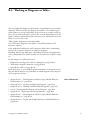
B-7 Exchanging Messages .................................................................................................................. B-139
B-7.1
Receiving Messages ...................................................................................................................... B-139
B-7.2
Sending Messages ......................................................................................................................... B-140
Index .................................................................................................................................................................. B-145
Copyright © 2010 MID GmbH
III
Part B Working with Innovator
Each of these Innovator editions–which can also be supplemented by additional modules, such as the Nassi-Shneiderman editor, reverse engineering etc.–come with specific functions for quickly and consistently creating
and maintaining models of any size.
There are always similar or the same concepts at the heart of these editions,
even though the requirements between them can vary a lot: they create elements, display them in various contexts, link them to each other etc.
The following chapter will outline Innovator functions which are largely
independent from the Innovator edition used. You will learn how to:
• Structure the model and navigate between elements in the model browser (see chapter B-1, "Using the Model Browser", page B-3)
• Differentiate between elements and work with them (see chapter B-2,
"The Basics for Working with Innovator", page B-17)
• Gather information about model elements and use the search function
(see chapter B-3, "Searching for Information", page B-81)
• Work with diagrams and tables (see chapter B-4, page B-99)
• Use classes in the class browser (see chapter B-5, page B-125)
• Use references between elements to navigate or structurally connect
these with each other (see chapter B-6, "Using Model References", page
B-133)
• Work with the mailing system in Innovator (see chapter B-7, "Exchanging Messages", page B-139)
You can select whether names need to be unique in the entire model or not
when working with Innovator Object or Innovator Business editions. You
can find all information about namespaces in chapter B-2.6, "Reducing
File Path Components Using Namespaces", page B-64.
Read about versioning model elements in the Manual
Version Management.
Read about comparing model elements in the Diff Utility Manual.
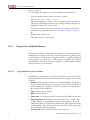
There is often more than one way to execute menu items.
You can configure menu items for the menu bar, the context-sensitive popup menu and the toolbar. You can also use shortcut keys.
Only the menu items will normally be given in the Innovator documentation. However, particularly with regard to standard functions, other alternative operations are often more productive.
Copyright © 2010 MID GmbH
Alternative Operation
1
• Shortcut keys
Switching from keyboard to mouse takes up valuable time. There are,
therefore, shortcut keys available for standard functions (e. g. [Alt]+[Enter]
for the Element|Edit/Properties dialog box). You can find the
shortcut keys which are available to you in the menu after the respective
menu item.
• Toolbars
You can customize the left, top and right toolbars by assigning a toolbar to
the menu items which have been assigned an icon in the model browser
and the editors using the Extras>Customize>Toolbars... menu
item.
You can display icons for create templates in the left-hand toolbar in the
model browser. You can display verifications and engineering actions in the
top toolbar.
To display create templates for model elements as icons, select Model>
Configuration><Element Type>>Diagram Properties, <Element Templates>... or Diagram Templates...
To display verifications or engineering actions as icons, select Model>
Configuration>Verifications or Engineering Actions and
activate the Show in Model Browser Toolbars check box.
• Menu bars and pop-up menus
You can select menu items which should be displayed in the menu bar or
in the pop-up menu with Extras>Customize>Menu or Popup Menu
from the respective menu item structure from the model browser, diagram
or table editor. Menu items which are selected but are not applicable are
not grayed out in the pop-up menu; they are not even displayed. Model
configuration of dependent menu items, such as e. g. verifications, are selected as groups using the respective submenu.
2
Manual classiX B Operations Innovator 11
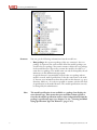
B-1 Using the Model Browser
If you open a model in Innovator, a main window appears first and then
the model browser. This is the central window which you will use to carry
out many of the basic tasks associated with modeling:
• You can manage the structure of your model using packages (see page
A-35)
• You can navigate to the various elements of your model (see page B-13)
• You can use model-internal or -external references for navigating or for
structured connection of two models (see page B-133)
• You can carry out the most important basic functions (e.g. creating, deleting, moving, opening, renaming elements, see page B-17)
Copyright © 2010 MID GmbH
3
B-1 Using the Model Browser
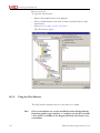
B-1.1
Structure of the Model Browser
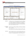
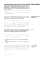
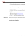
The model browser is divided into various areas.
4
Model Tree
The model's structures are shown in the left-hand area of the model browser, the model tree. You use so-called packages here which you–depending
on your model's requirements–hierarchically structure (see page B-5).
You can use hierarchical diagrams in some editions (e.g. SA diagrams in the
Innovator Function edition, activity diagrams in the Innovator Business
edition). As these diagrams also represent a part of your model's structure,
they are shown in the model tree as well.
List of Model
Elements
If you select an entry (package or diagram) in the model tree, all elements
which are included in it are shown in the center area; the list of model elements (see page B-8).
Various information about the elements are shown in the columns of lists.
You can change the order of the columns and hide columns (see page B-9).
Detail View
You can assign further elements to some elements whilst working on the
model (e.g. attributes of a class, refinement of a data dictionary entry). If
you select one of these elements in the list of model elements or in the result region, the corresponding information is shown in the detail view.
Manual classiX B Operations Innovator 11
B-1.2 Viewing the Model Structure in the Model Tree
You can display and hide the detail view separately in the View menu or
with the corresponding icon.
You can only view the contents of precisely one package or one hierarchical
diagram in the list of model elements. However, you need a collection of
elements for some tasks, regardless of which package they are in (e.g.
searching for elements with certain properties).
You can collect, select and, as necessary, use as many elements of a model as
required in the result region (see page B-11). Information about a selected
element is shown in the detail view.
Information about the element is also shown in various columns in the result region. As with the list of model elements, you can also change the order of the columns and how they are shown (see page B-9).
You can display and hide the result region separately in the View menu or
with the corresponding icon. You can set the result region so that it is automatically displayed as soon as an element is assigned in the dialog box
Extras/Options using the check box Pop result region automatically.
B-1.2
Result Region
Viewing the Model Structure in the Model Tree
All your model's packages and hierarchical diagrams are shown in the model tree. This means you can view your model's tree structure at a glance.
• chapter A-3.1, "Working with Packages", page A-36
• chapter A-3.2, "Modeling Dependencies Between Packages in Package
Diagrams", page A-45
• chapter A-3.4, "Making Specifications to Packages", page A-60
• chapter B-2.2.3, "Working with Hierarchical Diagrams", page B-35
• chapter B-1.3.3, "Changing the Order of Entries", page B-10
B-1.2.1
Other Information
Using Information in the Model Tree
You can represent hierarchies in Innovator using packages and some diagrams. You can manage tree structures which occur in this way in the model tree.
Copyright © 2010 MID GmbH
5
B-1 Using the Model Browser
6
Structure
You can get the following information from the model tree:
• Root package: the top-most package of the tree structure is the root
package. It represents the entire model. All of the model's packages are
stored in the root package. You cannot rename or delete the root package
in the model browser. You need to rename the model to be able to rename the root package. The model name can only be changed by the administrator in the administration program.
A special element is automatically created in the root package when a
model is created: model specification. It has the same name as the model. You can store information about the model on this element (e.g. specifications, labels etc.). It is also not possible to rename or delete the model specification in the model browser. The model specification can only
be changed by the administrator.
Note
The model specification is not available as a package, but displays its
own element type. This means that you can define various specifications for the model specification and use these independently from the
package's specification types (see chapter C-2.4.2, "Creating and Modifying Specification Types for Elements", page C-27).
Manual classiX B Operations Innovator 11
B-1.2.2 Opening, Closing and Releasing Subtrees
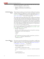
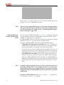
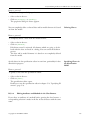
• Subtrees: As many packages and hierarchical diagrams as required can
be stored in the root package–as long as it methodically makes sense.
Each of these elements, in turn, can be assigned sons. Each package or
hierarchical diagram which contains a son therefore represents the root
of a subtree. If an element contains children, a '+' or '-' sign is displayed
in front of the element name. By clicking on these signs you can expand
or collapse the subtree of the element.
The element contains children. However, the subtree is currently collapsed
and not visible.
The element contains children. The
subtree is currently expanded and all
children are displayed.
The element does not contain any
children. It represents the end of the
subtree.
• Package type: as well as their name, packages have a property–the socalled stereotype value. Each stereotype value can be associated with an
icon (see page A-78). This icon is displayed before the package name.
B-1.2.2
Opening, Closing and Releasing Subtrees
You can open and close the subtree of each package in the model tree.
However, this is only possible if the package contains son packages, i.e. has
either a '+' or a '-' symbol before its name.
You can also set the model tree in such a way that only a certain subtree
should be shown.
How to proceed
To open a subtree, there needs to be a '+' symbol before the package's
name:
» Click on the '+' symbol.
The package's subtree is shown.
How to proceed
To hide a subtree, there needs to be a '-' symbol before the package's name:
» Click on the '-' symbol.
The package's subtree is hidden.
Copyright © 2010 MID GmbH
7
B-1 Using the Model Browser
How to proceed
To only display the subtree of a certain package in the model tree:
» Select the package whose subtree you want to release.
» Select View>Hide Higher Levels.
The selected package is shown as the root package in the model tree.
The arrow pointing upwards above the package indicate that the tree
displayed is only a part of the model.
» To show the entire model again, select the root package of the subtree
currently being displayed and select View>Show Higher Levels.
or
» Double-click on the arrow.
The entire model is shown again.
B-1.3
Using the List of Model Elements
If you select a package or diagram in the model tree, all elements which are
included in it are shown in the list of model elements. In a package, these
are the elements (model elements, diagrams, tables etc.) which are assigned
to the package (see page B-53), as well as their son packages. For a hierarchical diagram, these are its refinement diagrams, as well as model elements
which are shown in the diagram.
B-1.3.1
Using Information in the Columns
A multitude of information is stored for each element. You can view the
following information directly in the model browser using the list of model
elements:
• Number: all of a package's elements are serially numbered. The elements
are also stored in the repository in the given order. If this is about the elements displayed in a package, the order of numbers corresponds with
those shown in the model tree.
• Type: element type of element
• Name: name of element
• Shortname: if an element can have a shortname this will be shown here.
• Path component: Each element exists precisely once in a model. The
package which it is e.g. displayed in is the owning package. The path
component which is shown in this column is the path component of the
owning package. The element can also be referenced with as many packages as required (reference packages).
• Creation time: date which the element was created on
8
Manual classiX B Operations Innovator 11
B-1.3.2 Changing the Order of Columns in the List of Model Elements or Result Region
• Modification of time: date which the element was last modified on
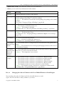
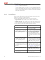
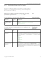
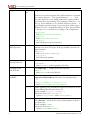
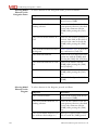
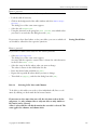
• Status: you can read various information in this column:
Display
Meaning
0 to 999
Current generation (version) of the element
R or empty
R: The element in this package is only a reference; the actual element is stored in
another package (the package is a reference package).
(empty): The element is stored in the current package–the package is the owning
package.
(see section "Category of Usage of Packages", page A-60)
L, - or (empty)
L: The element is locked by you.
-: The element is locked by another user.
(empty): The element is unlocked.
(see chapter B-2.1.4, "Reserving Elements for Editing (Locking)", page B-28)
A or (empty)
A: You always have access rights to the element (if you lock it, you can modify it).
(empty): You do not have access.
(see chapter A-1.2.6, "Assigning Privileges and Element Rights to User Groups",
page A-16)
T or (empty)
T: Text is stored about the element.
(empty):No text is stored for the element yet.
(see chapter C-2, "Specifying Elements", page C-9)
* or (empty)
*: The element (classes or components) has one declaration in the primary lan-
(only Innovator
Object)
guage.
(empty):The element has one or more project languages, however, these are not
in the primary language.
r or (empty)
r: The components were reserved by a user so that they cannot be exported more
(only Innovator
Object and
Innovator
Business)
than once as a source text from the model.
(empty): The component is not reserved.
B, O, D, F, R, *
B: The element contains a reference to an element in a Business model.
O: The element contains a reference to an element in an Object model.
D: The element contains a reference to an element in a Data model.
F: The element contains a reference to an element in a Function model.
R: The element contains a reference to an element in a Report model.
*: The element contains one or more references to other models.
(empty):The element contains a reference to an element in another model.
or empty
(see chapter B-6, "Using Model References", page B-133)
B-1.3.2
Changing the Order of Columns in the List of Model Elements or Result Region
You can change the order of columns in the list of model elements or result
region. You can also hide as many columns as you want.
Copyright © 2010 MID GmbH
9
B-1 Using the Model Browser
How to proceed
To change the order of the columns:
» In the model browser, select Extras>Options....
The dialog box of the same name appears. All column titles of the list of
model elements are listed in the list box Table configuration.
» Set whether you want to change the columns of the list of model elements or those of the result region in the group box Table configuration.
» In the list box Table configuration, select the column's entry
whose position you want to change and move it to the correct position
using [Up] or [Down].
» Select the column's entry and activate the check box Hide to hide the
column.
» Click on [Apply] and close the dialog box with [OK].
The order of the columns is adapted accordingly.
B-1.3.3
Changing the Order of Entries
The entries in the list of model elements are arranged in the order in which
they were created as standard. You can change the order of entries. The following options can be used for this.
• You can sort the entries according to specific columns. You can sort each
column apart from according to the status.
• You can enter any order. You can use this procedure to influence the order of the packages, how they are displayed in the model tree. Elements
are also correspondingly taken into consideration in the model documentation.
Note
If you only sort the entries, each entry keeps its number in the repository. If, however, you change the order, in doing so, you also change the
numbering.
How to proceed
To sort the entries in the list of model elements or result region:
» If necessary, role the desired column so it can be seen in the window.
» Click on the column heading of the relevant column.
The entries are sorted.
» To reverse the sort order, click on the column head again.
10
Manual classiX B Operations Innovator 11
B-1.4 Collecting as Many Elements as Required in the Result Region
How to proceed
To arrange the entries in any order:
» Lock the package which contains the entries.
» If necessary, click on the column head of the column which contains the
numbered entries.
The entries are sorted according to their position in the repository.
» In the list of model elements, click on the entry whose position you want
to change and drag it to the correct position keeping the mouse button
pressed.
The order of the entries and their numbering are adapted. When you
have moved a package or a hierarchical diagram, the order is also
changed in the model tree.
B-1.4
Collecting as Many Elements as Required in the Result Region
You can only view the contents of precisely one package or one hierarchical
diagram in the list of model elements. However, you need a collection of
elements for some tasks, regardless of which package they are in (e.g.
searching for elements with certain properties).
You can display, sort, select and, as necessary, use as many elements of a
model collected as required in the result region.
You can transfer elements in the result region in the following ways:
• Manually using the menu or using drag-and-drop (see page B-12)
• Using the search function (see page B-81)
You can sort the entries according to columns in the result region.
Note
The result region is automatically displayed in the model browser under
Extras>Options... as soon as an element is assigned.
• chapter B-1.3.2, "Changing the Order of Columns in the List of Model
Elements or Result Region", page B-9
• chapter B-1.3.3, "Changing the Order of Entries", page B-10
• chapter B-1.5.3, "Finding an Element's Package", page B-15
Copyright © 2010 MID GmbH
Other Information
11
B-1 Using the Model Browser
Transferring Elements
in the Result Region
You can use elements which are displayed in the model browser's result region in exactly the same way as in the list of model elements: You can lock,
rename, delete etc. them. In this chapter you will learn how to manually
transfer elements in the result region. You can read how to get hits from
the search function in the result region in chapter B-3, page B-81.
You can transfer the following set of elements in the result region:
• Selected elements
• The contents of a package
• The contents of a package and all of its son packages
Read how to select elements in chapter B-2.2.5, page B-40.
How to proceed
To manually transfer elements in the result region:
» Select the package in the model tree with the elements which you want
to transfer in the result region.
» Select the desired element/s.
» Select Edit>Result Region>Add Selection.
or
» Add the selected element to the result region using drag-and-drop.
The elements only appear additionally in the result region.
» Repeat this for all packages which contain the necessary elements.
How to proceed
To transfer all of a package's elements in the result region:
» Select the package in the model tree with the elements which you want
to transfer in the result region.
» Select Edit>Result Region>Add Content.
All of the package's elements (incl. son packages) only appear additionally in the result region.
» Repeat this for all packages which contain the necessary elements.
How to proceed
To transfer all of a package's elements as well those of its son packages in
the result region:
» Select the package in the model tree with the elements which you want
to transfer in the result region.
» Select Edit>Result Region>Add Content Recursively.
All of the package's elements, as well as all the elements in its son packages only appear additionally in the result region.
12
Manual classiX B Operations Innovator 11
B-1.5 Navigating in the Model Browser
» Repeat this for all packages which contain the necessary elements.
You can manually remove elements which are shown in the result region.
Deleting Elements
from the Result
Region
How to proceed
To remove an element from the result region:
» Select the element/s in the result region which you want to remove and
select Edit>Result Region>Remove Selection.
The elements are no longer displayed in the result region.
B-1.5
Navigating in the Model Browser
Only one section of the model can be shown on the screen at one given
time. You can navigate through the model's subtrees to be able to view the
desired elements in various ways:
• Use the incremental search to quickly select a package or diagram.
• Change between the packages in a higher or subordinate level in the
model tree.
• You can change from an element–e.g. in the result region or in detail
view–to an element's owning package and, in doing so, see the element's
context.
• chapter B-1.2, "Viewing the Model Structure in the Model Tree", page
B-5
• chapter B-3, "Searching for Information", page B-81
B-1.5.1
Other Information
Selecting an Entry in the Model Tree
You can use an incremental search to quickly search for a certain entry
(node) in all trees which are shown in the Innovator, e. g. in the repository
tree, in the model tree and in the overview tree of the documentation. The
tree behaves in exactly the way as in Windows Explorer.
This function is also available to you in the list of model elements and in
the result region.
Copyright © 2010 MID GmbH
13
B-1 Using the Model Browser
How to proceed
To select a certain entry in the model tree:
» Enter the character and, if necessary, the following character in the string
(this must be done within the space of a second) which the element
which you want to select begins with.
The first entry which best matches your entry in the part of the model
tree shown is selected.
» If more than one entry begins with the same character order, repeat the
entry.
B-1.5.2
Navigating Between Packages
If your model is extremely comprehensive, it is not possible for all packages
to be shown at the same time in the model tree. You can also use the model
tree's scroll bar to roll the desired package so that it can be seen on the
screen. However, you can also use keys to switch adjacent packages.
The following functions are available:
• Switching to an adjacent package on the same hierarchy level (above or
below)
• Switching to the first subordinate package
• Switching to the parent package
Note
Editions which permit hierarchical diagrams treat these as packages in
the model tree.
Looking Through the
Model
In addition to the scroll bar, you can also use the keys to look through the
model tree.
How to proceed
To switch to an adjacent entry in the model tree:
» Select a package in the model tree and press the [Up] or [Down] arrow
keys.
How to proceed
To be able to see another image window in the model tree:
» Use the scroll bar to roll the desired section so it can be seen on the
screen.
or
14
Manual classiX B Operations Innovator 11
B-1.5.3 Finding an Element's Package
» Press the [Page Up] or [Page Down] keys.
How to proceed
To switch to an adjacent previous package on the same hierarchy level:
» Press the key combination [Alt]+[Up] arrow key.
The package on the same hierarchy level which is above is selected.
How to proceed
To switch to the next adjacent package on the same hierarchy level:
» Press the key combination [Alt]+[Down] arrow key.
The package on the same hierarchy level which is below is selected.
How to proceed
To switch to the first subordinate package:
» Press the key combination [Alt]+[End].
The first son package is selected.
How to proceed
To switch to the parent package:
» Press the key combination [Alt]+[Home].
The parent package is selected.
B-1.5.3
Finding an Element's Package
Elements of a package which is selected in the model tree are shown in the
list of model elements. There are various ways to find out whether the element in this package is "at home" (i.e. whether the package is an owning
package):
• The path component which is shown in the Path column is identical to
the path component of the current package (see page B-4).
• The R (for reference) is not shown in the Status column (see page
B-8).
• You jump to the element's owning package.
Read about the differences between packages and reference packages in section "Category of Usage of Packages", page A-60.
Copyright © 2010 MID GmbH
15
B-1 Using the Model Browser
How to proceed
To jump to an element's owning package and, in doing so, show the element's context:
» Select the element in the result region, detail view or list of model elements.
» Select Jump>To Element.
The element's owning package is selected in the model tree.
» To jump back to the original element again, select Jump>Back.
16
Manual classiX B Operations Innovator 11
B-2 The Basics for Working with Innovator
With such a wide diversity of objectives and needs which you will find solution methods for in Innovator, whether you want to create simple displays of your model structures or prepare implementation for complex
software solutions, you will have to repeat some tasks numerous times
when working with Innovator.
This chapter deals with concepts, procedures and recommendations which
form the basis of all tasks which you perform using Innovator.
You can use the following specifications–largely independent from the
methods used or the Innovator edition–to gain an understanding of relationships which make the tool so powerful and versatile. You will then be
able to use Innovator for all your needs.
For most tasks, Innovator uses consistent mechanisms. These are the topics
covered in this chapter. In particular cases, deviations from these standard
procedures may be necessary if methodical requirements make it so. A detailed description of how to proceed in these cases is included in the manuals for the individual Innovator editions.
In this chapter you will learn
• How to distinguish between the various elements of your model (see
chapter B-2.1.1, "Disambiguation: Element Types, Model Elements,
Relationships etc.", page B-19)
• Why some elements can be displayed in various views even though they
only exist once (see chapter B-2.1.2, "Logical and Graphic Existences of
Model Elements", page B-22)
• How you can ensure that your work will not conflict with that of your
team colleagues when working on multi-user installations (see
chapter B-2.1.4, "Reserving Elements for Editing (Locking)", page
B-28)
• How to create (see page B-33), modify (see page B-49) and delete (see
page B-61) the various model elements.
• Which requirements exist for uniqueness of names and how these requirements can be influenced (see chapter B-2.6, "Reducing File Path
Components Using Namespaces", page B-64)
Copyright © 2010 MID GmbH
17
B-2 The Basics for Working with Innovator
B-2.1
Information about Elements in Innovator Models
Innovator is a tool which supports you during planning, implementation
and maintenance of projects–software projects in particular.
Various methods form the basis for this–depending on the objective and
the programming language. The fact that the project is split and separated
into small modules is something that all methods have in common. These
modules are placed in relation to each other, so that ultimately one picture
of the project–the model–is generated.
This means that Innovator is initially a graphic tool which you primarily
use to create diagrams to portray certain aspects and relationships. However, this description does not do Innovator's performance justice. Each module contains one specific semantic which enables extensive test mechanisms, consistency throughout the models and, last but by no means least,
code generation.
You can include various modules in each method. In this way, you can use
e.g. terminators, processes and stores, to specify data flows in structured
analysis. You can specify function calls using operations, storage areas and
parameters in structured design.
However, you use actors use cases etc. for system and software requirements in object-oriented programming. You can include classes and components, as well as their dependencies and relationships for the system's design.
You will learn which methodical meaning an element specifically contains
in the corresponding chapters of the Innovator editions. The following
chapter deals with which concepts you have to be aware of if you want to
use the elements for more than just for diagrams.
Three Resources for
Modeling
18
There are three resources available to you in Innovator for modeling your
project:
• Model elements: these are the foundations which your model is made
up of. Depending on which method you use in Innovator, various model
elements are available: You create them, set the required properties and
store commentarial text about the model element.
• Structuring the model: You can group your model's model elements as
many times as required and hierarchically structure the groups. In doing
this, you obtain a structure of the model. This facilitates communication
within the project team and maintenance of the model elements. You
use so-called packages to structure the model.
• Displaying model elements and their relationships: If the model
elements are shown once, you can view these from the most varied of angles: You display them in diagrams, tables etc. and add their relationships
to other model elements.
Manual classiX B Operations Innovator 11
B-2.1.1 Disambiguation: Element Types, Model Elements, Relationships etc.
B-2.1.1
Disambiguation: Element Types, Model Elements, Relationships etc.
You will frequently come across terms which require further explanation
when working with Innovator. The most important will be explained for
you here to begin with.
The foundations which your model is made up of are called model
elements. The form of your graphic display is specified by the method's
notation (e.g. SA processes as a circle, objects and UML classes as a rectangle). You can influence the display in some cases (e.g. classes as an icon
instead of a rectangle). Which information needs to be included in the
model element is also set in the methods (e.g. name, numbering, type or
stereotype). Depending on the Innovator edition, model elements can also
include further elements (e.g. include class attributes and methods) or can
be refined using diagrams (e.g. SA process, activity or business process
modeling).
In Innovator, model elements have special properties:
Model Elements
• A model element only exists precisely once in a model in precisely one
package. However, it can be assigned to (referenced therein) more than
one package.
• Model elements can also be displayed in one or more diagrams. You can
only create and display relationships between model elements there.
• Model elements have a maximum of one name.
• You can only store text for model elements.
You can read about which properties a model's model elements can contain
and how you can assign these properties in the chapters in the respective
Innovator editions. You can read how to work with the model elements,
i.e. create and delete them, arrange them in diagrams, in the following
chapters.
For a complete modeling, it is not enough to simply create and specify you
model's model elements. You also need to specify the relationships between
model elements.
Relationships between model elements can have considerably different
meanings, depending on your model's methods and on the current context, e.g.:
• Data transport: in SA diagrams, you can use the relationship between
processes, terminators and stores to display how data should flow and
how model elements change this.
You can display transfer parameters between operations as calls in the
structured design's operation diagrams.
You can specify the object flow in activity diagrams in the Innovator
Business and Innovator Object editions, i.e. which documents or information should be edited or processed by which activities.
Copyright © 2010 MID GmbH
Relationships
19
B-2 The Basics for Working with Innovator
• Relationship: you mainly display model elements and their relationships to each other in object-oriented methods, as well as with data modeling. You can e.g. examine which inheritance, composition or association relationships exist between classes here.
You can use relationships to display dependency relationships between
model elements in packages at the packages level.
• State transition: if the state of a model element changes due to results,
you can display this using state transitions.
These relationships are all graphically portrayed as lines in the model's diagrams. They can be directional–i.e. arrow points to one or both ends–or
nondirectional. A relationship's appearance is set in the notation of the respective methods (e.g. whether the line is drawn through or dotted, curved
or straight).
Note
20
Relationships are not shown in the model browser.
Elements
The term "element" is used as an umbrella term for model elements and
relationships (or other graphic elements as well) throughout this book for
specifications which do not depend on a methodical meaning of a certain
model element or a relationship, but rather Innovator functions which you
can use (e.g. Element>New or Element>Rename).
Element Types
There is a specific set of element types (e.g. classes) available for you in
each method. You can display model elements of one or more element
types in diagrams. The element types have specific relationships between
themselves. These relationships are also from a specific element type in
each case.
The usable element types are method-dependent and therefore dependent
on the respective Innovator edition.
• Diagram types: you can e.g. find diagrams of the use case diagram type,
class diagram, sequence diagram etc. in the Innovator Object edition
edition. Whereas, in the Innovator Function edition edition, you use diagrams of the SA diagram, operation diagram and module diagram type.
• Types for model elements: only elements from extremely specific types
are permissible in diagrams of a type. This means that you can only use
model elements of the actor, use case or system type in use case diagram,
whereas in class diagrams, you can only use model elements of the class
type.
• Types for relationships: relationships between model elements are also
specially adapted to the diagrams: This means that you can only use data
flow in an SA diagram while transitions are reserved in the state diagram.
Manual classiX B Operations Innovator 11
B-2.1.1 Disambiguation: Element Types, Model Elements, Relationships etc.
You can set certain properties at the same time for model elements of a
type (e.g. fonts in diagrams of various types). Properties which you assign
to an element type can normally be overwritten at a later date for individual elements of this type. You can set the following properties for element
types:
• Fonts and colors
• Element colors
• Labels
• Text templates
• Property values
• Filter
You can set the following properties individually for each element type in
the editors for diagrams and tables:
• Pop-up menu
• Toolbar
• Colors
This means that you can e.g. set other entries in the pop-up menu for SA
diagrams, as in operation diagrams.
Each model element in Innovator is stored in precisely one package. Packages can be divided hierarchically. This means that you can create entire
package structures. Which package you create an element in (or which
package you move an element to) solely depends on the structure requirements of your model. Read about the differences between packages and
reference packages in section "Category of Usage of Packages", page A-60.
Packages
You can examine model elements in your model under the most varied of
aspects. You can choose between various display forms for each of these aspects:
• Diagrams: diagrams enable the graphic display of model elements, in
particular, their relationships to other model elements. You can display
one and the same model element in any desired number of diagrams (in
which the model element is permissible).
Views of Model
Elements
• Tables: tables are also a special view of certain elements. They display relationships in the form of structured text.
• model browser: you can display your model in its hierarchical structure
here. You can identify the package structure and which model elements
are in which package. The model browser is consequently the table of
contents of your model.
Diagram refinement is apparent in methods which support hierarchical
diagrams (e.g. SA diagrams in structured analysis, activity diagrams in
BPM).
No relationships between model elements are displayed in the model
browser.
Copyright © 2010 MID GmbH
21
B-2 The Basics for Working with Innovator
B-2.1.2
Logical and Graphic Existences of Model Elements
A model element only exists precisely once in a model. It is identified by
its name, element type and the path component in the package hierarchy.
All specifications which are available for the model element (name, path
component, text, date of creation or modification, creator's user name etc.)
are always stored in the repository together with the model element. Collection of all data of a model element is referred to as a logical existence of
this model element.
However, a model element can be displayed in any number of diagrams
(or in none as well). Some model elements can even be displayed more
than once in a diagram (e.g. the bar in SA diagrams). However, it always
concerns the same model element: The same data always forms the basis,
regardless of which display you are viewing the specifications in. This naturally also means that modifications to data which you make with an element's existence also affects all other existences. Model elements are displayed as graphic existences of a model element or reference to a logic existence of the model element.
Note
Graphic display is not mandatory. It can by all means be possible that a
model element exists logically in an element but is not graphically displayed in a single diagram.
At first glance, this statement doesn't seem to be anything special. However, some mechanisms are linked with this issue, which are perhaps not initially visible.
22
Creating vs. Adding
You need to take the difference between the logical and graphic existences
of a model element into consideration if you want to display a model
element in a diagram: you need to decide whether you want to create a
model element which has not existed before in the model before or whether you want to display a model element in the current diagram which is already available in the model. To do this, use
• The Insert><Element Type>>New menu item for creating a model
element
• The Insert><Element Type>>Add Existing... menu item for
displaying a model element again
Display
In some diagrams, you cannot identify whether the model element was created here or whether it was added in the diagram.
Exceptions:
• In SA diagrams, added processes are marked with an asterisk (*).
• In some cases, the package path of the model element can be entered.
Manual classiX B Operations Innovator 11
B-2.1.2 Logical and Graphic Existences of Model Elements
As with creating or adding a model element, you also need to take logical
or graphic existences into consideration if you no longer want to depict a
model element in a diagram. You need to decide whether the model
element should be deleted from the entire model, and with it, all of its displays, or whether only one of its references should be removed from the diagram. To do this, use
• The Edit>Delete menu item for deleting a model element from the
model
• The Edit>Remove from Diagram menu entry for removing the reference of a model element
Deleting vs. Removing
So far we have only addressed which concept lies at the heart of adding
model elements in a diagram. The question still remains as to how this
concept affects the relationships between model elements.
Firstly: you will spend ages searching for a Insert><Relationship>
menu item to no avail. Adding in diagrams is exclusively reserved for
model elements (exception: dependencies between packages, see page
A-50). You can, however, display relationships which a model element in
the model has to other model elements: assign it a maintenance status. You
can use this to set whether which relationships this model element has in
the model should be shown in the current diagram. Read how to work
with the maintenance status in chapter B-2.1.3, page B-24.
Adding and Removing
Relationships
The maintenance status is a reference to a model element, i.e. you can
assign another maintenance status in each diagram which depicts the
model element, which having an influence on other diagrams.
Note
This means that relationships between two model elements can therefore
be displayed in more than one diagram. If you no longer wish to display a
relationship in a diagram, you need to decide whether this should only be
removed from the current diagram or whether you want to delete the relationship from the entire model. To do this, use
• The menu item Edit>Delete for deleting a relationship from the
model
• The menu item Edit>Remove from Diagram for removing a relationship
You can copy some model elements and insert them into the desired new
position again. At first, this function doesn't see particularly complicated,
as it is known from other applications. However, in Innovator some fairly
complex mechanisms are concealed behind the actual copying itself: Depending on where you insert such a copied model element, sometimes you
create a new model element, sometimes you merely add another graphic
existence.
Copyright © 2010 MID GmbH
Copying–When
Creating, When
Adding
23
B-2 The Basics for Working with Innovator
Read about the intricacies and secondary effect in chapter B-2.2.8, "Copying Elements", page B-45.
This basically applies:
• If–within a model–you insert a copied model element in the model
browser, you also create a new model element in the package which is
selected at the time.
• If–within a model–you insert a copied model element in a diagram, you
add a model element in doing so, and therefore only create another
graphic existence of the model element.
• You can only insert a model element which you have copied using the
model browser again via the model browser. You can only insert a model
element which you have copied in the diagram again in a diagram.
B-2.1.3
Displaying Relationships to Model Elements from Other Diagrams (Maintenance
Status)
You can view one and the same model element from various angles by displaying it in various diagrams. Display a part (section) of relationships to
other model elements in each diagram and, in doing so, emphasize certain
conditions in a targeted manner.
Example
Note
24
One of these perspectives could be present: "I want a diagram which really
shows all relationships of the current model element to other model
elements."
To do this, you can obviously trawl through all the diagrams looking for
this model element and subsequently combine all existences and relationships in one diagram. This means that you regularly have to manually root
out possible extensions of the model and carry out maintenance in your diagram by adding relationships to model elements in the diagram and reconstruct the corresponding relationships.
You can also let Innovator do this maintenance for you. Add the model
element in the diagram and assign it the property of maintenance throughout the models. Innovator then automatically depicts all relationships
which contain this model element in the model in the current diagram as
well. Innovator automatically adds all necessary model elements in the diagram for this purpose. If other relationships to model elements are added
anywhere in the model at a later date, these will also be added to the diagram. This means that your only task is to occasionally position the model
elements which were added automatically so that they are clear in the diagram.
Each model element should be displayed in at least one diagram with
all its relationships i.e. in its entirety. The easiest way to do this is set
the maintenance status of this model element to Complete model in
at least one diagram.
Manual classiX B Operations Innovator 11
B-2.1.3 Displaying Relationships to Model Elements from Other Diagrams (Maintenance Status)
You can set the maintenance status for the following model elements:
• In ER and SER diagrams: entities with their relationships
• In class diagrams: classes with their relationships
• In component diagrams: components with their relationships
• In package diagrams: packages with their dependencies
• In SD module diagrams: modules with their calls
• In SD operation diagrams: operations and data fields with their calls
Model Elements which
can be Maintained
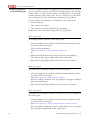
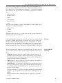
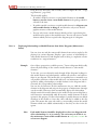
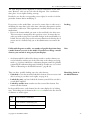
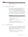
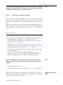
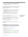
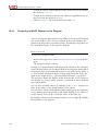
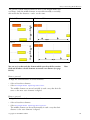
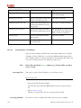
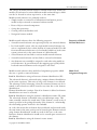
Innovator differentiates between three stages of diagram maintenance:
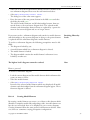
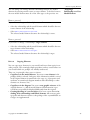
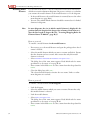
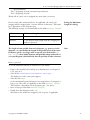
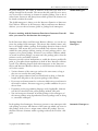
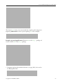
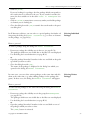
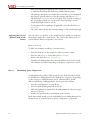
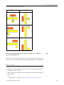
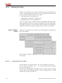
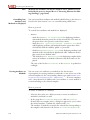
• Complete model: all relationships which exist to the model element
in the entire model are always shown. This can lead to new model
elements with the related relationship being automatically added in this
diagram. The added model elements contain their own maintenance status Local in diagram. This means that all existing relationships of a
model element are visible during global maintenance.
Types of Maintenance
Diagramm 1
Diagramm 2
B
A
D
A
C
Diagramm 3
A
E
Diagramm 3
A
B
D
E
If you want to jump to a model element which is depicted in more than
one diagram using the menu command Jump, the target diagram is
asked for in a list. The diagrams which have model elements with the
Complete model maintenance status are marked in the list by an asterisk (*).
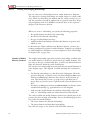
Note
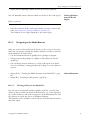
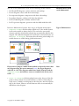
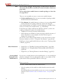
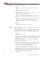
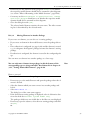
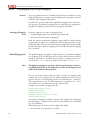
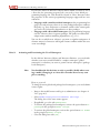
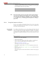
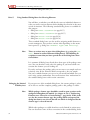
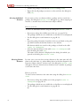
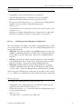
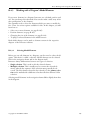
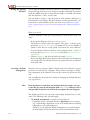
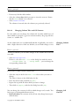
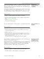
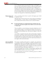
• Local in diagram: all relationships between the objects of this diagram are always shown. If a model element, to which a relationship already exists, is added to the diagram for the first time, then this relationship is also shown. However, model elements will not automatically be
added from other diagram.
Copyright © 2010 MID GmbH
25
B-2 The Basics for Working with Innovator
Diagramm 1
A
a
B
Diagramm 2
Diagramm 2
a
A
b
B
A
b
B
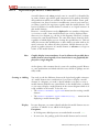
• User defined: only those relationships are shown, which you have
added to this diagram. Automatic maintenance does not take place.
Note
If you remove (not delete) a relationship, in doing so you switch the
maintenance status of the model elements involved to User defined.
With immediate effect, Innovator no longer automatically maintains
the relationships of these model element in the diagram.
Maintenance Status
According to
Relationship Type
You can only set the fact that relationships of classes or components will
be maintained using the maintenance status in class and component diagrams. You can also specify which relationships should be maintained here.
Two groups of relationships are distinguished between here:
• Associations, aggregations: you can set whether the maintenance
should only have an effect on navigable relationships or on all of them.
• Generalizations, dependencies, interfaces: you can set whether only
the relationships to the parents should be maintained or on all of them.
26
Assigning
Maintenance Status
when Adding
You set the maintenance status when adding an element. You can also
change them at a later time.
Note
You can set which maintenance status added and created elements
should have for classes and components using templates (see section
"Setting the Maintenance Status of Elements", page A-107).
Manual classiX B Operations Innovator 11
B-2.1.3 Displaying Relationships to Model Elements from Other Diagrams (Maintenance Status)
How to proceed
To set the maintenance status when creating a model element:
» Jump to the diagram and lock it if necessary.
» Select Insert><Element Type>>Add Existing....
The dialog box of the same name appears. Model elements which can
be maintained have one Maintenance tab or group.
» Activate the radio button for the desired maintenance status.
» Click on [Apply] and close the dialog box with [OK].
You can change the maintenance status of a model element (a reference to
the element) at a later date.
Changing the
Maintenance Status
How to proceed
To assign a maintenance status to a reference to a model element at a later
date:
» Jump to the diagram and lock it if necessary.
You do not need to lock the model element, as you only change the depiction, not the logic when carrying out maintenance.
» Select the model element and select Edit>Properties....
The dialog box of the same name appears. All model elements which
can be maintained have a tab Maintenance.
» Select the tab Maintenance.
In most cases, you will find the group box Maintenance here. For
classes and components, there is one group for each group of relationships.
» Activate–if necessary, in the group which specifies the relationship
types–the radio button for the desired maintenance status.
» If you want to limit the relationship types to certain cases for classes and
components, activate the check box Navigable relationships
only or Relations to required elements only.
» Close the dialog box with [OK].
If you manually remove relationships from a diagram, the model's depiction is incomplete with regard to the model elements involved.
In the diagram, you can show whether all relationships of a model element
are completely displayed in a diagram, i.e. whether other relationships
apart from those which are currently visible exist in the model.
Showing Completeness
The display of the maintenance status is only available in diagrams
which have objects with a maintenance status (e.g. in class, component
and object diagrams).
Note
Copyright © 2010 MID GmbH
27
B-2 The Basics for Working with Innovator
The completeness of relationships is divided into three categories:
• All relationships which the model element has in the model are displayed. This also means that all model elements to which relationships
exist are displayed in the diagram. The name of the model element is
surrounded by a full frame.
• All relationships which the model element has to other model elements
in the current diagram are displayed. The element's relationships are locally complete. The element is not marked in any particular way.
This depiction implies that elements which have relationships still exist
outside of the diagram.
• All relationships of a model element are not displayed once within the
diagram: The relationships of the model element to other model
elements in this diagram are not fully displayed. This can be out of
choice, but could also point to an error. This can be identified by a
dashed frame around the name of the model element.
Note
Activating the
Completeness Display
Font and text color of the selected maintenance type influences how
model elements are displayed in ER and SER diagrams.
You can set how complete you want your display to be for all diagrams of
a type.
How to proceed
To show the completeness of relationships in model elements of a diagram
type:
» If necessary, go to a diagram of a diagram type.
» Activate View>Completeness Indicators.
B-2.1.4
Reserving Elements for Editing (Locking)
Innovator has its own locking concept which prevents multiple users from
editing the same element (model element, diagram, table, text etc.) at the
same time and, in doing so, overwriting changes.
All data of a repository is managed from a central location: the repository
server. All Innovator applications receive their information from the repository server and present it to the user. Only data which is relevant for the
current window is exchanged between your user interface and the server.
Changes to this data are immediately conveyed to the repository server.
Each user always works with the most current data, as there is no local
copy, and therefore no possible outdated copy of the project data.
28
Manual classiX B Operations Innovator 11
B-2.1.4 Reserving Elements for Editing (Locking)
The same diagram can be displayed on various workstations at the same
time. However, only one user can edit the diagram. User coordination
takes place via an explicit locking concept.
Provided a user has the corresponding access rights, he needs to lock the
particular element before modifying it.
If you want to alter model data, you need to ensure that no other user is
modifying the same data at the same time, otherwise discrepancies and inconsistencies could occur. This requirement is realized in Innovator by two
mechanisms:
• Reserve the element which you want to alter and lock it for other users.
This reservation is managed by the repository server. It ensures that no
other user with varying access can make changes in the model while it is
locked. You can only carry out the necessary functions for altering the element once it is locked. Only you or the administrator can remove the
lock.
Locking
Unlike with diagrams or tables, any number of graphic depictions from
a model element can exist in the model. If you want to change a model
element, you can lock it using any of your displays.
Note
• An element which is affected by changes made to another element can
not be locked by another user at the same time as the changes are being
made. e.g. A process which has a refinement diagram cannot be globally
renamed if the refinement diagram is locked by another user (see section
"Effect of Renaming on the Model Structure", page B-49).
There are three possible locking states for each element:
• Unlocked: no user has currently locked the element. You can reserve and
edit it (as long as you have access rights, see page A-3).
• Locked (by you): you have locked the element yourself. You can edit it
as and when required.
Identifying Locks in
the Model Browser
• Locked by another user: another user has reserved the element. You
cannot edit the element.
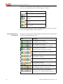
In the model browser, each element has the same display for its locking
state: The locking state is shown in the Status column in the list of model elements or result region.
(empty)
The element is unlocked.
L
The element is locked by you.
-
The element is locked by another user.
Copyright © 2010 MID GmbH
29
B-2 The Basics for Working with Innovator
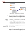
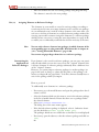
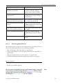
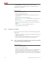
If you have activated the toolbar display in the model browser you can use
the icons to identify whether a selected element is locked:
Icon
Meaning
No lockable element is selected.
None of the selected elements are
locked.
All of the selected elements are
locked.
Both locked and unlocked elements
are selected.
The user name of the user who has currently locked the element is shown
next to the locked element in the status bar.
Identifying Locks in
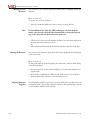
the Diagram
In diagrams, locking of the actual diagram and locking of a selected model
element are distinguished between:
Icon
Meaning
The diagram is not locked.
No lockable element is selected.
The diagram is not locked.
None of the selected elements are locked.
The diagram is not locked.
All of the selected elements are locked.
The diagram is not locked, however, both
locked and unlocked elements are selected.
The diagram is locked.
No element is selected.
The diagram is locked.
None of the selected elements are locked.
The diagram is locked.
All of the selected elements are locked.
The diagram is locked, however, both locked
and unlocked elements are selected.
You do not have access to the diagram.
(e.g. because of it being locked by another user).
30
Manual classiX B Operations Innovator 11
B-2.1.4 Reserving Elements for Editing (Locking)
Elements you have created yourself are at first automatically locked for
you, and you are assigned the access rights for them. In addition, you can
lock each element at different points at a later time (provided you have the
required access rights and no other user has locked it):
• As in the model browser each element of the model is shown (in some
cases several times), you can lock items for editing directly there.
• You can also lock model elements in each diagram in which a graphic
display of the model element exists.
• Model elements can also be locked directly in the dialog boxes Element>Properties... or Edit>Properties.... The [Apply]
button is replaced with the button [Lock] or [Unlock] until the
model element has the respectively required locking state. The locking
state is not changed by closing the specified dialog boxes.
• You can also lock diagrams and tables when opened.
Locking Elements
You can use the integrated Innovator messages to inform another user
that they should release a certain element (see page B-139).
Note
If a user has locked an element but is not currently available, the administrator can log the user out of the model and, in doing so, release
the elements (see page A-9).
If the administrator is also unavailable, the repository can be shut
down using -f (forced shutdown)–no other user can be logged on.
All locked elements are unlocked.
How to proceed
To lock any element (model element, diagram, package, table etc.) in the
model browser:
» Jump to the model browser.
» Select the package which contains the desired elements in the model
tree.
» Select the elements which you want to lock in the list of model elements.
If there is an element within the selected elements which is not yet
locked, the menu item Edit is shown in the Lock menu.
Read how to use elements from various packages at the same time in
chapter B-1.4, "Collecting as Many Elements as Required in the Result
Region", page B-11.
» Select Edit>Lock.
All selected elements which are not yet locked by you are reserved for
you. Elements which are locked by another user are ignored.
Copyright © 2010 MID GmbH
31
B-2 The Basics for Working with Innovator
How to proceed
To lock a model element in the diagram:
» Go to the diagram.
» Select the elements which you want to lock.
If there is an element within the selected elements which is not yet
locked, the menu item Edit is shown in the Lock menu.
» Select Edit>Lock.
All selected elements which are not yet locked by you are reserved for
you. Elements which are locked by another user are ignored.
How to proceed
To lock the current diagram:
» Click on a free point in the diagram.
If the diagram is not yet locked, the menu item Lock is shown in the
Diagram menu.
» Select Diagram>Lock.
The diagram is locked.
Unlocking Elements
Note
When you having finished working on an element you should release it
again. Other users cannot edit the element until this is done.
You can unlock all locked elements at the same time by logging-out of
the model and then logging-in again.
How to proceed
To unlock any element (model element, diagram, package, table etc.) in
the model browser:
» Jump to the model browser.
» Select the package which contains the desired elements in the model
tree.
» Select the elements which you want to unlock in the list of model elements.
If there is an element within the selected elements which is not yet unlocked, the menu item Unlock is shown in the Edit menu.
Read how to use elements from various packages at the same time in
chapter B-1.4, "Collecting as Many Elements as Required in the Result
Region", page B-11.
» Select Edit>Unlock.
All selected elements which are not yet unlocked by you are unlocked.
32
Manual classiX B Operations Innovator 11
B-2.2 Creating and Changing Model Elements
How to proceed
To unlock a model element in the diagram:
» Go to the diagram.
» Select the elements which you want to unlock.
If there is an element within the selected elements which is not yet unlocked, the menu item Unlock is shown in the Edit menu.
» Select Edit>Unlock.
All selected elements which are not yet unlocked by you are unlocked.
How to proceed
To unlock the current diagram:
» Click on a free point in the diagram.
If the diagram is locked, the menu item Unlock is shown in the Diagram menu.
» Select Diagram>Unlock.
The diagram is unlocked.
B-2.2
Creating and Changing Model Elements
Creating elements normally follows the same pattern:
• Diagrams: Apart from a few exceptions, diagrams are created in the
model browser (see page B-34). However, you can also create from an
open diagram in a refinement diagram which can be refined by other diagrams (e.g. SA diagrams, activity diagrams). In some diagrams you can
also create a supplementary diagram for a model element (e.g. a state diagram for a bar in the Innovator Function edition edition or one for
classes in the Innovator Object edition edition).
• Model elements: you can either create model elements in the model
browser (see page B-38) or in a diagram (see page B-39). To create a
model element means that it does not already exist in the model and you
are creating it as new. If the model element is created once, you can add
it to any number of diagrams (see chapter B-2.1.2, "Logical and Graphic
Existences of Model Elements", page B-22).
• Relationships: you normally create relationships between model
elements in diagrams (see page B-43).
A model-wide or package-wide default name is assigned to the element
upon creation as standard. You can change these names afterwards. However, you can set up your system in such a way that the dialog box appears
Copyright © 2010 MID GmbH
33
B-2 The Basics for Working with Innovator
which you can set element's properties in when the element is being created. For more information, read chapter B-2.2.1, "Enabling Creating with
Dialog Boxes", page B-34.
B-2.2.1
Enabling Creating with Dialog Boxes
Elements are created in Innovator without dialog as standard. The elements then get given a default name and a default layout with properties.
If the element is created, you can make the desired changes.
However, you can set your system in such a way that the dialog box Element/Properties appears immediately after an element is created.
This enables you to make the desired changes to the element straight away.
You make the setting individually for each editor (model browser, table editor, diagram editor). This means that you can e.g. set another setting in
the use case diagram, as in the class diagram or in the model browser.
How to proceed
To be able to immediately make changes when an element is created:
» Got to the editor which you want make the setting for.
» Select Extras>Options....
The dialog box of the same name appears.
» Activate the check box Set properties after creation in the
general tab.
» Click on [Apply] and close the dialog box with [OK].
If you create an element, the dialog box Element/Properties appears at the same time; you can make the desired changes here.
B-2.2.2
Creating and Opening Diagrams
You can create the majority of a model's diagrams using the model browser. The necessary steps are described over the following pages. If a diagram
type requires another procedure, you can find a detailed description of this
in the relevant chapter of the Innovator edition.
You can create diagrams which fulfill the following properties using the
model browser:
• The diagrams created in such a way are empty upon creation.
• You make a view which you can define yourself to a large extent.
• You can choose the name of the diagram.
34
Manual classiX B Operations Innovator 11
B-2.2.3 Working with Hierarchical Diagrams
In the editions Innovator Object and Innovator Business, you have farreaching configuration options for model elements and diagrams. You can
only create diagrams which already have templates or types configured for
them in the model here For more information, read
• How to create diagram templates (Innovator Object edition edition and
Innovator Business edition) in chapter A-4.3.5, page A-99.
• How to define and provide types of diagrams (Innovator Business edition edition) in chapter D-7.2, "Enabling Creation Diagrams", page
D-186.
• chapter B-2.3.1, "Changing Names, Relationships and Declarations",
page B-49
• chapter B-2.2.1, "Enabling Creating with Dialog Boxes", page B-34
• chapter B-2.2.3, "Working with Hierarchical Diagrams", page B-35
• chapter B-2.3.2, "Moving Elements in Another Package", page B-53
Other Information
How to proceed
To create a diagram with the model browser:
» Jump to the model browser and select the package where the new diagram should be stored in the model tree.
You will find all menu items which you can use to create corresponding
elements in the current package in the Element>New Diagram submenu.
» Select the entry of the diagram which you want to create in the Element>New Diagram submenu.
The diagram is created in the current package. It contains a model-wide
or package-wide unique default name.
» To open the diagram, select the corresponding entry in the list of model
elements and select Element>Open.
B-2.2.3
Working with Hierarchical Diagrams
You can portray hierarchies using some diagram types in Innovator, i.e. refine certain elements. This means that every refinement diagram depicts a
detailed view of a model element in a higher-level diagram. Hierarchical diagrams are e.g.
• SA diagrams from the Innovator Function edition edition for processes
• Activity diagrams in the Innovator Object and Innovator Business editions for activities
Tree structures result from refinement; they can be used for special functions. In this chapter you will learn how to
• Create an empty refinement diagram to a model element (see page B-36)
Copyright © 2010 MID GmbH
35
B-2 The Basics for Working with Innovator
• Transfer one or more of a diagram's model elements together into a new
refinement diagram (see page B-36)
• Resolve a hierarchy level by replacing a model element with the model
element of its refinement diagram (see page B-37)
Note
Creating an Empty
Refinement Diagram
to a Model element
You can only create the top-most level of a hierarchy in the model
browser (see page B-34).
You can create an empty refinement diagram either in the model browser
or in the diagram which contains the model element. The refinement diagram is created in the package which also contains the model element.
Neither the diagram nor the model element which you want to refine must
be locked if you want to create an empty refinement diagram.
How to proceed
To create an empty refinement diagram to a model element:
» Select the model element. Ensure that only this model element is selected.
» Select Element>New Diagram><Diagram Type>.
An empty diagram of the highlighted model element is opened. It contains the name of the model element.
Transferring Several
Model Elements in a
Refinement Diagram
If several model elements already exist in a diagram and you want to transfer these together into a (new) refinement diagram, in doing this you create
a new model element in the current diagram, which replaces the relocated
model element.
To e.g. transfer model elements from an SA diagram into a new refinement diagram, the following prerequisites must be fulfilled:
• If stores or terminators are selected, all model elements which are directly linked with them by flows also need to be selected.
• If one of the selected model elements is the source of a split flow, either
no or all target elements need to be selected.
• If one of the model elements is the target of a merge flow, either no or
all source elements need to be selected.
How to proceed
To transfer model elements from the current diagram to a refinement diagram:
» Lock the current diagram.
36
Manual classiX B Operations Innovator 11
B-2.2.4 Creating Model Elements
» Select one or all of the model elements which you want to transfer to the
new refinement diagram. Please note the rules mentioned above.
» Select Edit>Hierarchy>Insert Level....
The dialog box of the same name appears.
» Enter the name of the new parent element in the field Name and close
the dialog box with [OK].
The selected model elements and all relationships between them are
moved down to the next lowest diagram level. The selected model
elements and relationships between them are replaced by a parent element in the current diagram and are no longer shown.
If you want resolve a refinement diagram and transfer its model elements
and relationships to the top-most diagram, in doing so, the parent element
is replaced with the refinement diagram's model elements.
To resolve a refinement diagram, the following prerequisites must be fulfilled:
•
•
•
•
Resolving Hierarchy
Levels
The diagram is locked by you.
A model element which has a refinement diagram is selected.
The model element is locked.
The diagram which contains the model element's refinement is not
locked by another user.
The highest level's diagrams cannot be resolved.
Note
How to proceed
To resolve a refinement diagram:
» Lock the current diagram and the model element which refinement diagram you want to resolve.
» Select the model element.
» Select Edit>Hierarchy>Resolve Level.
Instead of the selected model element which was displayed, all model
elements and relationships from the refinement diagram appear. The refinement diagram is deleted.
B-2.2.4
Creating Model Elements
By creating a model element you create a set of data to this element which
identifies it uniquely model-wide and package-wide. A model element can
but does not necessarily have to be displayed in one or more diagrams.
Creating elements follows the same pattern in all Innovator editions. However, there are sometimes varying prerequisite configurations.
Copyright © 2010 MID GmbH
37
B-2 The Basics for Working with Innovator
Note
You can always configure which package a model element should be redirected to, which will be created in the context of another element (see
page A-68).
You can also assign a model element to another package at a later date
(see page B-53).
There are can normally two ways to create most model elements:
A: Via the model browser: You can enter any number of packages which
should contain the model element.
B: Via a diagram: the model element is–as long as it is not configured differently–created in the package which also contains the diagram.
Some model elements can only be created in diagrams, especially if they
cannot be viewed in the model browser, e.g. relationships.
In the Innovator Object and Innovator Business editions, you have farreaching configuration options for model elements:
• Templates are necessary for many model elements.
• Other elements are relinked to certain stereotypes with the existence of
classes. Read how to create templates for these element types in
chapter A-4.3.2, page A-91.
You can also create various model elements in the class browser in these
Innovator editions (see B-5.2, "Using the Class Browser", page B-126).
Read how to insert copied model elements in the section "Copying within
a Model", page B-47.
More Information
Creating Model
Elements via the
Model Browser
• chapter B-2.2.1, "Enabling Creating with Dialog Boxes", page B-34
• chapter B-2.3.1, "Changing Names, Relationships and Declarations",
page B-49
• chapter B-2.3.2, "Moving Elements in Another Package", page B-53
If you create a model element in the model browser, it is not initially displayed in a diagram. You can subsequently add it to any number of diagrams which contain permissible elements of this type.
How to proceed
To create a model element with the model browser:
» Select the package in the model tree which should contain the model
element.
You will find all menu items which you can use to create corresponding
elements in the Element>New or Element>New Diagram submenu.
38
Manual classiX B Operations Innovator 11
B-2.2.4 Creating Model Elements
» Select the entry of the model element which you want to create in the
Element>New or Element>New Diagram submenu.
If it is permissible, the model element is created in the current package.
Otherwise, select a package from the dialog box which appears.
It contains a model-wide or package-wide unique default name.
When you create a model element via a diagram, you implicitly carry out
two steps:
• You create the model element in the model, i.e. you create the minimum
data set that identifies a model element (element type, name, package
path).
• You create a (first) graphic existence of the model element in the diagram, i.e. you add the model element to the diagram (see page B-22).
For each diagram type in Innovator, it is specified which model elements
are permitted in these diagrams. This means you cannot create any desired
model elements in each diagram, but instead only those that are also practical.
The special toggle menu item Insert><Element Type>>Add existing exist for reusing existing elements of business process models. If
this is activated, then it changes the property of the remaining Insert
menu items such that no new element of the type can be created, but instead one can be chosen from those which already exist.
The number of model elements in a diagram is not limited by the system.
However, a number below ten is recommended to maintain a clear structure.
Creating Model
Elements via the
Diagram
You can set the maximum permissible number of model elements in
various Innovator editions. You can use a corresponding Innovator verify option to check that the procedure is being adhered to.
Note
How to proceed
To create a model element with a diagram:
» Jump to the diagram and lock it.
You will find all menu items which you can use to create corresponding
elements in the current diagram in the Insert menu. The menu items
in the Insert menu are divided into additional submenus in some
Innovator editions.
If you do not enter a position for the model element, a default position
is selected.
» If you want to create the model element in a certain position, click on
this position in the diagram.
Copyright © 2010 MID GmbH
39
B-2 The Basics for Working with Innovator
» Select the entry of the model element which you want to create in the
Insert– or the desired submenu.
The new model element is–as long as it is not configured differently–
created in the package which also contains the diagram and is placed, if
necessary, on the marked position. It contains a model-wide or packagewide unique default name.
B-2.2.5
Selecting Elements
Before you can edit elements in the model browser, you need to select
them first. This choice is called a selection.
Innovator always differentiates between two types of selection:
• Single selection: This is usually used to edit the selected element
• Multiple selection: This is usually used to collect the selected elements
in the result region, whereby the sequence of the selection is irrelevant.
To select elements in the model browser, proceed as follows:
40
Objective
Procedure
Selecting an element
Click on the element with the left
mouse button [LMB]
Selecting elements of a hierarchy
level in the same area of the model
browser, expanding selection
Select the first element, then click
on an element of the same hierarchy level with the [LMB] while
pressing the [Shift] key; all elements of this hierarchy level lying
between these two elements are selected
Selecting several desired elements
in the same area of the model
browser, expanding selection
Select the first element, then click
on any desired element in the same
area of the model browser with the
[LMB] while pressing the [Ctrl]
key
Selecting all model elements in the
list of model elements or in the result region
Click on an element with the
[LMB], then select the menu item
Edit>Select All or press the
key combination [Ctrl]+[A]
Deselecting individual elements
Click on the element with the
[LMB] while pressing the [Ctrl]
key
Cancel selection
Click in a free area
Manual classiX B Operations Innovator 11
B-2.2.6 Granting Access Rights to Elements
To avoid accidentally opening numerous windows, you will be asked to
confirm the command if you carry out the corresponding command as
a multiple selection of up to ten model elements.
B-2.2.6
Note
Granting Access Rights to Elements
You can transfer access rights which you as a user have for individual elements to other user groups. You have these access rights if you e.g. created
an element yourself. You do not require administrator rights to transfer
these.
If you have the element right to an element (and can therefore transfer it to
other user groups), then it will be shown in the list of model elements in
the model browser. These elements are shown in the Status column by
an A.
How to proceed
To transfer the access rights to a particular element to another user group:
» If necessary, go to the model model browserbrowser and enlarge the list
of model elements so that the Status column can be seen.
The element rights which the user group has currently selected are
shown in the Status column.
» Select Model>Administration>Maintain Access Rights....
The dialog box of the same name appears. All user groups of the current
model are listed in the list box Select a group list.
» Select the user group which you want to transfer certain element rights
to in the dialog box.
You can work in the model tree while the dialog box is open.
» Select the element in the list of modellist of model elements elements
whose access rights you want to transfer to another user group.
If you accidentally select an element which you do not have access
rights to, then this element will be ignored when the access rights are
assigned.
Note
» In the dialog box, click on [Set].
All of the selected elements are shown in the Status column by an A.
Whereas all users can grant element rights to other groups, only the administrator can withdraw these rights again (see chapter A-1, "Managing
Users, Groups and Rights", page A-3).
Copyright © 2010 MID GmbH
Withdrawing Element
Rights
41
B-2 The Basics for Working with Innovator
B-2.2.7
Creating and Changing Relationships
You can only create relationships between model elements in diagrams.
The options for creating relationships are usually subject to certain conditions, which are affected by the method and the current context. As a result, the procedure can only be explained in very general terms here. If special prerequisites need to be fulfilled, read about these in the respective
chapter of the Innovator editions.
When you create a relationship, you specify the following properties:
• the model elements involved in the relationship
• the direction for directed relationships
• the type of relationship if necessary
• with hierarchical relationships, which model elements are parents and
which are sons
In the Innovator Object and Innovator Business editions, you have farreaching configuration options for model elements. Templates are provided
for relationships here. Read how to create templates for these relationships
in chapter A-4.3.3, page A-93.
Number of Model
Elements Involved
The simplest relationship–apart from recursive relationships, in which only
one model element is involved–is that between two model elements. You
can only set the type of relationship here, as well as–for directed relationships–the direction which the arrow should point.
You can also create relationships between more than two model elements in
some diagram types. This depends on which meaning this construction
has:
• For directed relationships (e.g. data flow in the SA diagram, call in the
operation diagram), you always create one relationship from one source
element to several target elements; this is because of the selection options. This means that you can e.g. easily create a split flow, but no
merge -flow (you need to create a split flow and reverse the direction for
this).
• You always set one parent element and one or more son elements for hierarchical relationship (e.g. generalization in a class diagram).
• Only enter the model elements involved for relationships of the same
value (i.e. relationships which are neither directed nor hierarchical).
The order in which the model elements involved are selected plays an important role when creating relationships. You set the following upon selection of the first model element:
• The source element for directed relationships
• The parent element for hierarchical relationships
You select the target or son elements with all further selections.
42
Manual classiX B Operations Innovator 11
B-2.2.7 Creating and Changing Relationships
If more than one element is selected, you can change the primary selection by clicking on the element (without pressing the shift key) which
you now want to be the primary selection.
Note
The diagram must be locked during all of the following tasks.
How to proceed
To create a relationship between model elements:
» Open the diagram and lock it.
Creating relationships is subject to certain prerequisites. If one or more
of these conditions are not met then the relationship cannot be created.
Read which conditions need to be met in the corresponding chapters of
the Innovator editions.
Note
You will find all menu items which you can use to create corresponding relationships in the current diagram in the Insert menu. The menu items
in the Insert menu are divided into additional submenus in some
Innovator editions.
Inserting
Relationships
How to proceed
To create a relationship:
» Select
- The source element for a directed relationship
- The parent element for a hierarchical relationship
- Any model elements involved for relationships of the same value
» Also select all further model elements which are involved in the relationship.
» Select the entry of the relationship which you want to create in the Insert– or the desired submenu.
The selected model elements are linked by a line.
- Directed relationships are shown by an arrow from the relationship
first selected to the other linked model element/s.
- For hierarchical relationships, the parent element is identified by the
specific depiction of the relationship.
You can also create a recursive relationship or a relationship between two
elements using the mouse. As described above, you do this by selecting a
model element, clicking on the icon of the desired relationship, moving the
mouse pointer with the rubber band over the element to which a relation-
Copyright © 2010 MID GmbH
43
B-2 The Basics for Working with Innovator
ship is to be created and clicking on this element. Model elements for
which the conditions for creating a relationship are met, are marked in color when they are moved over with the mouse (as with the selection).
Reversing the
Direction
The direction of the relationship is set by the order in which the two
model elements are selected. You can still change this direction in most cases.
How to proceed
To reverse the direction:
» Select the relationship whose direction you want to change. Ensure that
all segments of the relationship are selected.
» Select Edit>Properties....
The dialog box of the same name appears. If you can reverse the direction, a group or a tab Direction exist.
» If applicable, select the tab Direction.
In the group box Direction, either an alternative is specified for each
direction:
- option button von <bish. Quellelement>
- option button zu <bish. Quellelement>
Or an check box Invert direction is shown.
» If you want to exchange source and target elements, activate the option
button zu <bish. Quellelement> or the check box Invert direction.
» If you want the relationship to flow in both directions, activate the option button Bidirectional.
» Close the dialog box with [OK].
The dialog box closes, all selected relationships are reversed.
Linking Segments
You can link a relationship with a model element at a later date. This needs
to be done individually for each segment. No segment of the relationship
can already be linked with the new model element.
How to proceed
To link a segment with another model element:
» Select the segment which you wan to link with another model element.
» Also select the model element which you wan to link with the segment.
» Select Edit>Reconnect.
The segment is linked with the new model element.
44
Manual classiX B Operations Innovator 11
B-2.2.8 Copying Elements
You can change an existing directed relationship between two model
elements by entering another source or target element. To do this, however,
the new model element must be of the same type as the previous one.
Assigning a
Relationship to a New
Model Element
How to proceed
If you want to change a relationship's source element:
» Select the relationship and the model element which should be the new
source element of the relationship.
» Select Edit>Reconnect>Source.
The selected model element becomes the relationship's source.
How to proceed
If you want to change a relationship's target element:
» Select the relationship and the model element which should be the new
target element of the relationship.
» Select Edit>Reconnect>Target.
The selected model element becomes the relationship's target.
B-2.2.8
Copying Elements
You can copy most elements in your model and insert them again in another position. This seemingly simple procedure can have certain effects on
your model which are perhaps not initially understood.
There are, in principle, three ways to reinsert:
• Copy/Insert in the model browser: You create a new element in the
package which is selected. Only part of the information which is stored
in the original element is transferred to the copy (e.g. if properties and
attributes are transferred, diagram members and relationships to other
elements are, however, lost).
• Copy/Insert in the diagram: You create a new graphic existence of the
original element, i.e. add the model element. All information is preserved but can possibly be displayed differently from the original.
• Creating/checking-in a version object: You create a new element including all its relationships and linked elements. All necessary package paths and elements–relative to the package of the «systemModel» stereotype–are supplemented.
Copyright © 2010 MID GmbH
45
B-2 The Basics for Working with Innovator
Questions when
Inserting
The effects when copying primarily apply to which details of a copied element should be inserted again.
• General:
- How are the names of the elements dealt with? How is uniqueness ensured?
- Should the package path be adopted?
• Model element:
- Should the model element's components (e.g. attributes of a class, parameters of a call) be copied as well?
- Which linked elements (e.g. assigned components of a class, decision
tables of a process, refinement diagrams) should be copied as well?
• Diagrams:
- Should the model elements be copied into the new diagram with all
their properties or should just their name be created?
- How are the relationships between the diagram's model elements
treated?
• Packages:
- Which part of the package's content is copied?
Example
In diagram A, the model elements a, b and c and their relationships to one
another are displayed.
• Select the elements A, a and b in the model browser and copy them. In
the same model/system model, select any package and insert elements
(Edit>Paste>As New Element). The following elements are created:
- a diagram A_1
- Model elements a_1 and b_1
In diagram A_1–as in the original diagram–the model elements a, b and
c and their relationships which are visible there are displayed. The new
model elements a_1 and b_1 exist, but are (still) not displayed in a diagram ("non-active members").
It is sufficient to copy diagram A to achieve the same effect–though
without "non-active members".
• In diagram A, select the model elements a and b and copy them. In the
same model/system model, open another diagram and insert elements
(Edit>Paste). The following elements are shown:
- Model elements a and b (as other graphic display)
- The relationship which was also shown in the original diagram
• Select the elements A, a and b in the model browser and copy them. In
another model/system model, select a package from the «systemModel»
stereotype and insert elements (Edit>Paste>Replace with Relations). The following elements are created:
- A diagram A
46
Manual classiX B Operations Innovator 11
B-2.2.8 Copying Elements
- Model elements a, b and c
- All relationships which exist between the model elements a, b and c
in the original system.
Read what to be aware of with these variants in section "Copying into
Another Model", page B-48.
When inserting elements you therefore need to check exactly which objective you are pursuing:
Note
• When creating new graphic displays of a model element within the
same system model (by copying the model element in the diagram or
by copying the diagram itself ).
• When transferring all relationships of the copied elements in another system model (by copying the diagram and the model element
which you want to display)
Use the As New Element or Replace with Relations menu item
in the model browser accordingly.
Within a system model it is sufficient to
• Use the simpler As New Element function in the model browser, as
the relationships have to be created at a later stage in every case here.
• Use the familiar function Paste in the diagram, as you only create another graphic display in every case here.
Copying within a
Model
In most cases a model element can only be displayed once in a diagram.
This means that another diagram normally has to be open to insert a
model element. Ensure that the same diagram type concerned is used
here.
Note
How to proceed
To copy a model element in the model browser:
» Jump to themodel browser and select the package which contains the
model element in the model tree.
» Select the desired element/s in the list of model elements.
» Select Edit>Copy. Select the package in the same system model
which should contain the new model element. Select Edit>Paste>As
New Element.
or
» Insert the selected element to the result region of the same system model using drag-and-drop.
The new model element is created and stored in the selected package. It
contains the names of the original element, supplemented by a unique
number throughout the models.
Copyright © 2010 MID GmbH
47
B-2 The Basics for Working with Innovator
How to proceed
To copy a model element in a diagram and to create a new graphic display in another diagram:
» Jump to the diagram and select the model element which you want to
copy.
» Select Edit>Copy.
» Open the diagram where you want to insert the copied element into. Ensure that this diagram is from the same diagram type as that of the copied model element.
» Lock the diagram and select Edit>Paste.
The model element is added in the diagram.
Copying into Another
Model
Whereas the simpler function As New Element within a system model
normally has the desired effects, it can lead to completely unexpected side
effects in another system model (model elements are created but not placed
in relation to others). Therefore, use the function Replace with Relations for actions spanning various models.
Note
If you only copy one diagram using the function Replace with Relations, the copy also actually contains all model elements and relationships which are in the original. However, if these do not contain
any information which exceeds pure graphics, then dependent elements
(e.g. attributes) are lost.
How to proceed
To insert a model element and all of its relationships (cf version object) in
another system model:
» Jump to themodel browser and select the package which contains the
model element in the model tree.
» Select the model element in the list of model elements. If you also want
to get the graphic depiction in another system model, select the diagram.
» Select Edit>Copy.
» Select the package–in the same or another model –from the «systemModel» stereotype under which the new model element should be
stored, and select Edit>Paste>Replace with Relations.
The package path to the new element/s is created, provided it is not
available. The model element and all other model elements which the
original element has relationships to are created. If you also copied the
diagram, this is also–in the correct package path too– created.
48
Manual classiX B Operations Innovator 11
B-2.3 Changing Name and Packages of Elements
B-2.3
Changing Name and Packages of Elements
If you have created an element it normally has a default name and a set of
default properties. You can also change names and properties at a later
time.
The properties (apart from the name) which you can change respectively
depend on the method and respective context. Read what to be aware of in
the corresponding chapters of the Innovator editions. The following chapter deals with names and packages of elements.
B-2.3.1
Changing Names, Relationships and Declarations
The name is a property of most elements in Innovator. The name and, if
applicable, the element's package path uniquely identify it within the model.
When specifying names, the following rules must be taken into consideration:
• If the global namespace is activated or preset in your model (see page
B-64), the name must be unique within the model.
• The name always needs to be unique within its package.
• The name is not normally longer than 127 characters.
Special constraints also apply for some elements with regard to permissible
characters. Read about this in the respective chapters of the Innovator editions.
Rules for Name
Specification
Some elements in Innovator can be linked with others. This means that
you can e.g. create a decision table or a refinement diagram for an SA diagram's process. Both elements are then linked with each other as they
have the same names. If just one of the elements is renamed then this link
is lost.
If you rename an element which is linked to other elements you need to
decide whether the respective other element should be renamed or whether
the link should be resolved.
If you rename a model element which has possible links, you can choose
whether the name change only takes effect in the current diagram or
whether the new name should also apply in other diagrams. You will come
across particular junctions for the effect on name changes depending on diagram and element types.
The following options are distinguished between in SA diagrams:
Effect of Renaming on
the Model Structure
Copyright © 2010 MID GmbH
49
B-2 The Basics for Working with Innovator
• Selected <element type>
The model element's name is changed exclusively in the current diagram. In refined SA processes, the e.g. flow diagram which is linked
with the process due to the names is not renamed. The link is also destroyed.
• All corresponding <element types> in the model
The model element's name is changed in all diagrams apart from the
refinement diagram. In refined SA processes, the e.g. respective flow diagram is not renamed. Assignment between the SA process and its refinement is also destroyed.
• All corresponding <element types> in the model with
refinement diagrams
The model element's name is changed in all diagrams e.g. also the
name of the corresponding flow diagram for refined processes. This conforms to a pure name change without changing the structure.
• Maintenance in Specifications, Tables and State Diagrams
The effect renaming has on other existences of the name can be determined by selecting references. In a process, the e.g. corresponding decision tables, as well as their activation, are renamed in the RT area. In a
terminator, the time requirements table is renamed.
Renaming Elements–
General
50
Elements are normally given a default name upon creation. You can rename each one of these elements afterwards. In some cases where the element is connected with others, if necessary, you need to take into consideration how they should be treated–whether they should also be renamed
or whether the link should be renamed (see page B-49). Otherwise the usual constraints for names apply (see page B-49) and, if necessary, methodlimited rules or syntax rules of a programming language.
You can basically rename an element in various positions:
• In the model browser: All elements which are shown in the model
browser
• In the diagram: You can rename the diagram itself as well as all model
elements here, as long as a name has been designated.
• In tables: Both the tables themselves and the model elements can be renamed here–as long as a model element is displayed.
The following prerequisites need to be fulfilled to be able to rename an element:
• The element must be locked by you.
• You need to have access rights to all elements which are linked with this
one as they have the same names (see page A-3).
• If you rename an element using a diagram, the diagram also needs to be
locked.
For model elements you need to take some side-effects which occur after
renaming into consideration. For more information, read page B-52.
Manual classiX B Operations Innovator 11
B-2.3.1 Changing Names, Relationships and Declarations
If you have activated the package-local namespace in the Innovator
Object or Innovator Business editions, you can use the check box Prevent duplicate names to set whether you want to receive a warning if the name already exists.
Note
How to proceed
To rename an element (model element, diagram, package) in the model
browser:
» If necessary, go to the model browser and open the package where the element is located.
» Select the element which you want to rename and lock it. Ensure that no
other element is selected.
» Select Element>Properties....
The dialog box of the same name appears. Read which rules for name
specification to be aware of on page B-49.
» Enter a name in the from the field Name or select a name from the dropdown list Name.
» Close the dialog box with [OK].
The selected element contains the new name.
How to proceed
To rename an element (model element, diagram, relationship) in the diagram:
» If necessary, go to the diagram which will display the element.
» Lock the diagram.
» If you
- Want to rename the diagram, click on a free point in the diagram.
- Want to rename a relationship (as long as a name is possible for a relationship), select the relationship–if necessary, using the relationship's
selection point.
- Want to rename a model element, select it and lock it
- Want to rename another element (e.g. attribute of a class, parameter
of a call), select the element
Ensure that no other element is selected in each case.
» Select Edit>Properties....
The dialog box of the same name appears. Read which rules for name
specification to be aware of on page B-49.
» Enter a name in the from the field Name or select a name from the dropdown list Name.
» Close the dialog box with [OK].
The selected element contains the new name.
Copyright © 2010 MID GmbH
51
B-2 The Basics for Working with Innovator
Renaming Model
Elements
Note
You can rename model elements at a later date. Differentiations made between model elements
which can contain refinement diagrams (SA process, activity) as to whether
you rename the model element in the model browser or in the diagram:
• In the model browser, the model element is renamed, but not the refinement diagram (see page B-49).
• You can select which linked elements should be renamed too for linked
elements in diagrams.
In some diagrams, the size in which a model element is displayed is dependent from the length of the longest line of names. Read how to reduce the line length in chapter B-2.4.1, "Learning Wrapping Rules for
Element Names in Models", page B-55.
How to proceed
To rename a model element in the model browser:
» If necessary, go to the model browser and open the package where the element is located.
» Select the model element which you want to rename and lock it. Ensure
that the element can have a name. Also ensure that only this model
element is selected.
» Select Element>Rename or Element>Properties....
The dialog box of the same name appears. Read which rules for name
specification to be aware of on page B-49.
» Enter a name in the field Name or select a name from the drop-down list
Name.
» Close the dialog box with [OK].
The selected model element contains the new name. Links to refinement diagrams are resolved.
How to proceed
To rename a model element in the diagram:
» Lock the diagram.
» Select the model element which you want to rename. Ensure that only
this model element is selected.
» Lock the model element.
» Select Edit>Properties....
The dialog box of the same name appears. Read which rules for name
specification to be aware of on page B-49.
» Enter a name in the field Name or select a name from the drop-down list
Name.
52
Manual classiX B Operations Innovator 11
B-2.3.2 Moving Elements in Another Package
» If necessary, use the junctions in the group box Effect to set whether
the respective model element should also be renamed in other diagrams
(see section "Effect of Renaming on the Model Structure", page B-49).
» f necessary, use the Maintenance in specifications, tables
and state diagram check box to set whether the respective model
element should also be renamed in other diagrams.
» Close the dialog box with [OK].
The selected model element contains the new name. The effect renaming has is determined by the selected mode.
B-2.3.2
Moving Elements in Another Package
If you create an element, you can also set it owning package:
• If you create an element in the model browser, enter the package directly.
• If no redirection is configured (see page A-68) and the element is created
e.g. via a diagram, the diagram's package becomes the element's owning
package.
• If redirection is configured, the element is stored in the configured package.
You can move an element into another package at a later stage.
You can only move elements into packages in which elements of the
corresponding type are also permissible. Read about this in chapter A3.4.1, "Setting Permissible Elements", page A-60.
Note
How to proceed
To move an element into another package:
» If necessary, go to the model browser and open the package where the element is located.
» Select the element which you want to move into another package and
lock it.
» Select Edit>Move to....
The dialog box of the same name appears.
» If the desired new owning package is displayed, select it. Otherwise deactivate the check box Current system model only.
The packages which were not visible due to the filter are now displayed.
» If necessary, open the subtrees, select the new owning package and click
on [OK].
or
Copyright © 2010 MID GmbH
53
B-2 The Basics for Working with Innovator
» Move the element into the new owning package using drag-and-drop.
The element is moved to the new package.
B-2.3.3
Assigning Elements to Reference Packages
The elements in your model are stored in various packages according to
certain criteria. In some cases many elements can be stored in one package.
As you will maybe won't need all of these elements at the same time, you
can store a selection of elements in so-called reference packages without destroying your model's structure: Assign the elements to a reference package
which you have easy access to using the access dependency (see page A-48)
to enable you to comfortably work with the selection necessary at the time.
Note
You can only reference elements into packages in which elements of the
corresponding type are also permissible. Read about this in chapter A3.4.1, "Setting Permissible Elements", page A-60.
You cannot assign packages themselves to a reference package.
Constraining the
Application of
Reference Packages
If an element is also stored in reference packages you can carry out practically all tasks which you can also carry out in the "original" elements; this
is because elements in reference packages ultimately show a different view
of the "original" element.
However, you cannot import reference packages in another package (see
page A-48) and, in doing so, reduce the file paths to this package's elements (see chapter B-2.6, page B-64). To do this, elements actually have to
exist in the package which you import.
How to proceed
To additionally store elements in a reference package:
» If necessary, go to the model browser and open the package where the element is stored.
» Select the elements which you also want to store in the reference package
in the list of model elements. Ensure that there are no packages under
the selected element.
» Select Edit>Create Reference in....
The dialog box of the same name appears.
» If the desired reference package is displayed, select it. Otherwise deactivate the check box Current system model only.
The packages which were not visible due to the filter are now displayed.
» If necessary, open the subtrees, select the reference package and click on
[OK].
or
54
Manual classiX B Operations Innovator 11
B-2.4 Wrapping Names of Elements
» Add the elements to the reference package using drag-and-drop.
The selected elements are additionally shown in the reference package.
Read how to enable direct access to elements in this package using the
access dependency and, in doing so, avoid a long-winded navigation
through the model tree in chapter A-3.2.3, "Producing Relationships
Between Packages", page A-48.
B-2.4
Wrapping Names of Elements
The name of a text element needs to be wrapped to be depicted in diagrams or tables; this achieves a satisfactory visual result.
To control wrapping of element names you can make general settings and
use special wrapping lists for targeted name wrapping.
You can use the following controlling options for wrapping element names:
• General settings (see page B-55)
• Wrapping lists for targeted wrapping (see page B-58)
B-2.4.1
Controlling Options
for Wrapping
Learning Wrapping Rules for Element Names in Models
If model elements do not fit within the existing available frame of the element, then need to be wrapped. This happens according to the following
strategy.
Wraps can occur at spaces and before and after special characters.
• Example: "Service-oriented" can be wrapped if there is another room to
become
General Wrapping
Rules
"Service-"
"oriented"
or
"Service"
"-oriented"
• Example: "Create account" can be wrapped to
"Create"
"account"
A wrap character is inserted at the wrapping point between the letters or
between letters and digits; this shows that the separated components do actually belong to each other.
Copyright © 2010 MID GmbH
55
B-2 The Basics for Working with Innovator
Wrapping can occur before a word component which starts with a capital
letter and is followed by a small-case letter.
• Example: "ERMEntity" can be wrapped to
"ERM-"(automatically inserted wrap character)
"Entity"
56
Individually Setting
Wraps
Word components made up of at least four letters which cannot be split according to the general wrapping rules are split corresponding to the model
element-based wrapping point. You can set this in the global wrap list, inowrap.txt, or model-specific in diagrams and tables using the Extras>
Edit Word Wraps... menu item (see page B-58).
The wrapping point of the model element name is utilized in the following
form for the wrap. The global and model-specific wrapping lists are always
searched through first for the entire word and upon an unsuccessful search,
the word component is then searched for and, if necessary, the wrapping
specification is used. The wrap character can also enable a wrap before and
after words. If there are individually characters between wrap characters because of the combination of various word components, no wrap character
is set to the left of the individual character.
You can use the wrapping specifications which you have already met in global or model-specific wrap list in the dialog box Extras/Edit Word
Wraps with the [Default] button.
• Example: "Administration"
If you have set the following decomposition in the global or model-specific wrap list for various word components
"-ad-min-"
"-is-trat-"
"-ion-"
then the following wrap characters will be inserted when you clock on
the [Default] button for "Administration"
"-Ad-min-is-trat-ion-"
Concrete Wrap in a
Frame
If the above wrap rules and specifications do not produce a suitable wrapping point in precise cases then the maximum length is generated from the
model options. These are set with the menu item Model>Configuration>General Settings... (see page B-57).
• Example for wrap designation in a longer word:
"Transfer_Kind_ExtPost"
can potentially be wrapped at these points
"Transfer-" (maximum length here: 8 characters; automatic wrap character)
"_"
"_" (special character)
"Kind" (beginning of word)
Manual classiX B Operations Innovator 11
B-2.4.1 Learning Wrapping Rules for Element Names in Models
"_" (special character)
"Ext-" (beginning of word; automatic wrap character)
"Post" (beginning of word)
Words will of course not be wrapped any more than is necessary.
If none of the rules mentioned above are applicable, the word to be
wrapped will be wrapped after a certain amount of characters. This number is dependent on the diagram types.
The following settings are recommended for the field Maximum length:
Edition
Maximum Length
Business
0
Function
> The longest string length from the wrapping list
without separators
The length of some model elements in diagrams–e.g. processes in SA
diagrams– are specified by the length of inseparable parts of the name.
If you have given a very large value or entered zero in the field Maximum length, these model elements will probably adopt undesired sizes in your diagram, which will also alter the position of other elements.
Setting the Maximum
Length of a String
Note
How to proceed
To set the maximum amount of characters for the model:
» Jump to the model browser and log-in as administrator (see chapter A1.2.1, page A-5).
» Select Model>Configuration>General Settings....
The dialog box of the same name appears.
» Select the tab Wraps.
Set the maximum length of characters in a string before it is wrapped, as
long as no other rules are applicable in the field Maximum length.
This number is dependent on the diagram types. (See above)
» Enter an integer in the field Maximum length.
» Finally, close the dialog box with [OK].
All names in the model are wrapped at the set point, if applicable.
Copyright © 2010 MID GmbH
57
B-2 The Basics for Working with Innovator
B-2.4.2
Using Wrapping Lists for Targeted Wrapping
General
As very specialized terms are normally used in Innovator models, it can be
highly problematic to integrate a general hyphenation program or general
word lists with wrapping information.
As well as the general, model-wide adjustable wrapping rules, Innovator
also manages user-defined wrapping lists for influencing the wrapping algorithm for displaying element names in diagrams and tables.
Managing Wrapping
Lists
Innovator supports two types of wrapping lists:
• A global wrapping list in the form of a special file and
• An internal model-specific wrapping list
Both the general, model-wide wrapping settings which are made and this
wrapping list are taken into consideration when displaying names in diagrams and tables. The internal model-specific wrapping list and is initially
searched through to find set wrapping points and then the global wrapping
list is searched.
Global Wrapping List
The global wrapping list applies for all repositories. It should be included
in a company in the terminology used in context with Innovator and this
should be available as a common glossary with set wrapping points. It is
stored in the $INODIR directory under the file name inowrap.txt.
Note
The global wrapping list can not be edited using Innovator interfaces,
as modifications made to the display has an effect on all diagrams and
tables of all models in all repositories.
You can use all terms whose wrap you want to control in a language-independent way in the wrapping list. the global wrapping list has one word
per line. You can set the wrapping points of a word using the '-' character.
This wrap character is not a word component–as opposed to the '-' characters which are entered directly into the element name.
Example extract from a wrapping list file:
Sales-rep-resent-ative
Competence-Group
Product-Direc-tory
Subject-Matter-Authori-zation
Insur-ance-Policy
You can have virtually any number of wraps in the wrapping list. Wrapping
lists with approx. 70,000 entries have been tested without any noteworthy
loss of performance.
When importing, all entries in the wrapping list which:
• Are not made up of precisely one word or
58
Manual classiX B Operations Innovator 11
B-2.4.2 Using Wrapping Lists for Targeted Wrapping
• Do not have wrap characters
• Include less than 4 characters
Only the first wrap character is observed for entries which are accidently
given twice.
How to proceed
To expand the global wrapping list:
» Open the inowrap.txt file in the $INODIR directory using the
ASCII text editor.
» Enter the words whose wraps you want to set each individually in a line.
Set the wrapping points by inserting the '-' character.
» Save the changes and close the file.
The global wrapping list inowrap.txt will be imported when a repository is started. Changes therefore only have an effect when a repository is
started. If a model contains a term from the global wrapping list, this is–if
necessary–wrapped at the defined position.
When expanding the global wrapping list, a model-specific wrapping list is
managed by the system for terms which are specially used within a model.
This internal wrapping list cannot be seen by the user, but is automatically
maintained by setting and resetting wrapping points in the model element
name and saved in the model. Wrapping list entries which are already set in
the global wrapping list are not saved in the model-specific wrapping list.
You can set and reset wrapping points in the model element name in a dialog box in the dialog or table editors; this alphabetically lists all words in
the selected element's names. If nothing is selected, all words in the diagram or table are listed.
Words in the global wrapping list appear in color. These wrapping list entries cannot be modified here.
You can select elements in the diagram or table, but not in the model tree,
as the effects are not visible there.
You can insert the wrap character '-' for the targeted wrap for the listed
words which do not appear in the global wrapping list. The wrap characters are not word components.
The dialog box is not modal. Selection of elements cannot be changed if
they remain open. This enables you to check the graphic effects.
Model-Specific
Wrapping List
How to proceed
To expand the model-specific wrapping list:
» Open the diagram or table whose model-specific wrapping list you want
to expand.
Copyright © 2010 MID GmbH
59
B-2 The Basics for Working with Innovator
» Select Extras>Edit Word Wraps....
The dialog box of the same name appears.
» Select the element in the diagram or the table whose name you want to
insert or remove wrapping points for.
Respectively, all words in the name of the selected element are alphabetically listed in the dialog box Extras/Edit Word Wraps. Words
in the global wrapping list appear in color. These wrapping list entries
can only be modified in the global wrapping list.
» Set the insertion point in the dialog box Extras/Edit Word Wraps.
Position it where you want to make the wrap and insert or remove the
wrap character '-'.
» Clock on [Apply] to check the wrapping points in the diagram or the
table.
if necessary, select other elements whose name you want to assign model-specific wrapping points to.
» Click on [Close] to end the procedure.
The model-specific wrapping list is stored in the model.
A model-specific wrapping list can be exported as a file so that it can be integrated into the global wrapping list.
Showing ModelSpecific Wrapping
Lists
You can show all of a model's model-specific wraps in the Innovator text
editor; you can do this to decide whether you wan to adopt these wraps in
the global wrapping list.
How to proceed
To show a model's model-specific wraps:
» If necessary, go to the model browser and log-in as administrator (see
chapter A-1.2.1, page A-5).
» Select Model>Word Wraps>Show in Text Editor.
All wraps set in the model are shown in the Innovator text editor.
Adopting ModelSpecific Wrapping
Lists in Global
Wrapping Lists
You can adopt model-specific wrapping lists in the global wrapping list. To
do this, export the model-specific wrapping list from the respective model
into a separate file (not inowrap.txt!) and join it with the global wrapping list.
How to proceed
To export the model-specific wrapping list:
» If necessary, go to the model browser and log-in as administrator (see
chapter A-1.2.1, page A-5).
60
Manual classiX B Operations Innovator 11
B-2.5 Removing and Deleting Elements
» Select Model>Word Wraps>Export....
The dialog box of the same name appears.
» Enter the directory and the file name for the file to be exported.
If you select a file which already exists you will be asked whether you
want to overwrite this.
All wraps set in the model are exported.
You can now use the model-specific wrapping list in the global wrapping
list.
The global wrapping list is stored in the $INODIR directory under the file
name inowrap.txt.
How to proceed
To join the model-specific wraps with the global wrapping list:
» Open the inowrap.txt global wrapping list and the exported file with
the model-specific wraps in an ASCII text editor.
» Insert all characters or selected lines of the model-specific wraps in the
global wrapping list.
The following step is not mandatory, however, sorting into alphabetical
order will make it easier to search for a name.
» Alphabetically sort the expanded global wrapping list and correct any
possible double entries.
» Save the inowrap.txt global wrapping list again in the $INODIR directory.
The expanded global wrapping list is now available.
B-2.5
Removing and Deleting Elements
Innovator differentiates between the logical and graphic existences of a
model elements (see page B-22). If you no longer need a model element,
you need to decide whether you only want to remove one of its graphical
existences (e.g. from a diagram) or whether you want to completely delete
the model element from the model.
You can normally only delete relationships between model elements, i.e.
completely remove them from the model. In some cases however, relationships–as with model elements–can be displayed in various diagrams or not
in any. In these cases you also need to decide whether you only want to remove the relationship from the current diagram or delete it from the entire
model.
Copyright © 2010 MID GmbH
61
B-2 The Basics for Working with Innovator
You can delete (not remove) elements in both the model browser and in a
diagram. On the other hand, you can normally only remove (not delete) an
element in diagrams. However, if you have assigned an element to another
package using a package reference in the model browser, you can also use
the command to execute the delete here (see page A-60).
Note
Locking Diagrams and
Elements
Deleting of elements cannot be undone!
Depending on whether you want to delete or remove an element, you need
to arrange for:
• Deleting
- To delete an element (model element or relationship) in a diagram,
both the diagram and the model element need to be locked in all cases.
- To delete an element (model element, diagram, package) in the model
browser, only the model element needs to be locked. Neither the owning nor the referenced package need to be locked. However, this package cannot be locked by another user.
- In this case, you need to have access rights to all diagrams which the
model element will be displayed in.
• Removing
- To remove an element (model element or relationship) in a diagram,
the diagram needs to be locked in all cases. The model element
doesn't need to be locked.
- To remove the reference to an element (model element, diagram) in
the model browser, you need to have access to the element. Neither
the owning nor the referenced package need to be locked.
B-2.5.1
Using Deletion Control
When deleting or removing elements, other elements could be affected by
the action. This means that e.g. relationships between model elements are
also removed or even deleted if one of the model elements involved is now
longer displayed.
As deleting or removing of an element cannot be undone it is necessary to
have a control option, which elements are affected by the action, to be able
to decide whether you really want to delete the elements.
You can set up your system in such a way that it shows a list of all affected
elements when deleting or removing. If an element which you don't want
to delete or remove is in this list then you can still cancel the entire procedure.
62
Manual classiX B Operations Innovator 11
B-2.5.2 Removing Elements
You cannot remove individual elements from the list. You can only delete/remove all or no elements.
Note
This can make this setting individually for the model browser, as well as
for every diagram and table type.
You can select whether the list of affected elements should be contained in
a dialog box or in an information window.
How to proceed
To set the deletion control:
» Got to the editor (diagram, table or model browser) whose elements you
want to set the deletion control.
» Select Extras>Options....
The dialog box of the same name appears.
» Select the General tab in the Delete Control line in the Value
drop-down list.
- List to Dialog if you want the list of elements in a dialog box
- List to Information Window if you want the list of elements
in an information window
- Off if you don't want any deletion control
» Click on [Apply].
» Close the dialog box with [OK].
In all editions of the current type you only get a list of elements which
are affected by the deleting or removing process.
B-2.5.2
Removing Elements
If you remove an element from the current diagram or the current package,
it remains in the model and, if applicable, in other diagrams.
How to proceed
To remove an element:
» If necessary, jump to the diagram and lock it.
» Select the elements you want to remove.
» Select Edit>Remove from Diagram.
If the deletion control is turned on (see page B-62), the dialog box of the
same name appears. All elements which are deleted by the action are listed.
Copyright © 2010 MID GmbH
63
B-2 The Basics for Working with Innovator
» Check whether you really want to remove the elements. If necessary,
cancel the procedure with [Cancel].
» Otherwise, close the dialog box with [OK].
The model elements and all relationships linked to them are removed
from the diagram.
B-2.5.3
Deleting Elements
When deleting, elements are removed from the model and therefore also
from all diagrams which they are used in.
How to proceed
To delete elements:
» Select the elements which you want to delete in the diagram or model
browser.
» If necessary, lock the diagram and all selected elements.
» Select Edit>Delete.
If the deletion control is turned on, the dialog box of the same name appears. All elements which are listed are deleted by the action.
» Check whether you really want to delete the elements. If necessary, cancel the procedure with [Cancel].
» Otherwise, close the dialog box with [OK].
The elements and all of the relationships link to them are deleted.
B-2.6
Reducing File Path Components Using Namespaces
If you reference a model element, i.e. connect a relationship from somewhere in the model, enter (at the very least) its name. Innovator then produces a relationship between the current element and the referenced element. If you e.g. rename the referenced element or move it to another
package at a later date, this change is also recognized in the referenced element and correspondingly reproduced.
Example
64
In the Innovator Object edition's class diagram, enter its type for an a attribute from the A class–i.e. the name of another B class: Reference the B
class (UML syntax: a:B).
Manual classiX B Operations Innovator 11
B-2.6 Reducing File Path Components Using Namespaces
In global namespace, the names of elements of the same type need to be
unique throughout the models. This means that file paths are never necessary if you want to reference an element in another package. Due to the element name, Innovator will always know which position the element can
be found at within the model.
The global namespace is always set in the Innovator Function or Innovator
Data editions. Whereas in the Innovator Object and Innovator Business
editions, you can choose between global or package-local namespaces.
Global Namespace
If you are working with the Innovator Function or Innovator Data editions, you cannot use the functions for namespaces.
Note
In the Innovator Object and Innovator Business editions, you can also activate the package-local namespace. This means that element names only
have to be unique within a package. Each package therefore forms a closed
namespace. This means that you can normally only reference elements
within the same package without entering an exact package path–i.e. the
sequence of its parent package. If however you reference elements which
are stored in another package, you must enter the package path so that the
reference can be successfully resolved.
Innovator provides various mechanisms to enable the shortest possible file
paths or even makes them superfluous in both of these Innovator editions
as well. The following chapter deals with namespaces in the Innovator
Object and Innovator Business editions, as well as functions which you can
use in this context:
Package-Local
Namespace
• Various elements of the same type can have the same name, as long as
they are not stored in the same package.
• You can separate subtrees from your model and, in doing so, limit the
length of the file paths to the top-most package of this subtree.
• If you enter an element name for a reference which exists several times in
the model or subtree, Innovator suggests a possible candidate for you to
choose from.
• Depending on the programming language used, if applicable, elements
can also be referenced in the parent package without a file path.
• You can incorporate elements of another package in the namespace of
the current package using dependencies between packages and, in doing
so, extend the namespace.
In the package-local namespace, Innovator generates a new namespace with
each package you create. All elements of the same type which you create in
this package need to have a unique name within the package. You can
therefore reference elements within a package without the need for a file
path.
Copyright © 2010 MID GmbH
Automatic Namespaces
65
B-2 The Basics for Working with Innovator
If you create classes in Innovator Object edition which you want to use at
a later date for generating program code, you need to enter which programming language the code should be created in. Here, Innovator takes
the properties of the various programming languages supported into consideration.
• Languages with a non-hierarchical namespace: this programming language can only reference classes in its own package/namespace (without
file path) (e.g. Java). References to elements outside of the current package need to be activated by dependencies to these packages.
• Languages with a hierarchical namespace: this programming language
can also reference classes in parent packages. File paths can omitted for
unique names without modeling dependencies (e.g. C++).
You can also set which areas (subtrees) you want to stipulate uniqueness of
element names for. Innovator will signal if name conflicts within this area
occur accordingly.
B-2.6.1
Activating and Deactivating the Use of Namespaces
In the editions Innovator Object and Innovator Business, you can decide
whether your entire model should be a unique namespace (global
namespace) or whether you want to permit various namespaces (packagelocal namespace).
Note
You should make this decision as early as possible, ideally when creating a model. Changing it at a later date can make for necessary complex re-working.
How to proceed
To change between global and package-local namespaces, you need administrator rights:
» Jump to the model browser and log-in as administrator (see chapter A1.2.1, page A-5).
» Select Model>Configuration>General Settings....
The dialog box of the same name appears.
» If applicable, go to the tab Namespaces.
» To activate the package-local namespace, activate the option button In
package in the group box Names unique.
» To activate the global namespace, activate the option button In model
in the group box Names unique.
» Close the dialog box with [OK].
66
Manual classiX B Operations Innovator 11
B-2.6.2 Differentiating between File Paths
B-2.6.2
Differentiating between File Paths
If you reference another element you need to enter which package the element is in in the package-local namespace (e.g. for types from class attributes). If you create such a reference you can either enter the required
file or select the desired target element using dialog boxes.
If Innovator could resolve a reference at one point, this relationship is
adhered, even if e.g. you rename or move the target element.
Note
Innovator differentiates between three ways to enter package paths:
• Unqualified reference
• Fully-qualified reference (see page B-68)
• Partially-qualified reference (see page B-68)
Depending on which project language you set as the primary language,
Innovator naturally shows or shortens the file path according to the project
language's requirements.
Only enter the name of an element. If this name is unique within the
namespace, Innovator can resolve the reference.
Example: Element E2 references element E1.
Unqualified File Paths
• For languages with a non-hierarchical reference (see page B-65) unqualified file paths are sufficient to find E1 in package P1_1. Whereas–
without file paths–the element E1 cannot be referenced in the package
P1.
• On the other hand, both E1 elements can be referenced without file
paths for languages with hierarchical references. Due to the collision of
names, however, the path component to P1 needs to be entered.
Copyright © 2010 MID GmbH
67
B-2 The Basics for Working with Innovator
If the name is not unique, Innovator uses the element which the current
package sets next for unqualified references.
Note
You can also use unqualified references for elements in other packages.
This means that the import dependency needs to be available between
the affected packages (see chapter A-3.2.3, "Producing Relationships
Between Packages", page A-48).
Fully-Qualified and
Partially-Qualified File
Paths
You can assign the additional property, topLevel, to packages. The package path therefore becomes an independent subtree below this toplevel
package (see chapter B-2.6.5, page B-72).
For fully-qualified references, the entire package path of all parent packages
affected is entered–i.e. up until the first toplevel package.
Two types of fully-qualified references are distinguished between:
• Full-qualification which spans all models: this is the only unique file
path which spans all models. It always contains the entire path component from the model's root package to the referenced element.
As the top-most level of you package structure normally only serves as an
organizational structure of your model and is therefore not relevant for
later implementation, this type of full-qualification is not be addressed.
• Full-qualification for subtrees: If you enter a path component for a
reference, Innovator searches for it below all (visible) toplevel packages.
This type of full-qualification has the advantage over full-qualification
which spans all models, that you can move the entire subtree within the
model without the references within the subtree needing to be recalculated.
Note
Languages with hierarchical references can also search for references in
the parent package of the current package. For these cases, Innovator
independently shortens the complete file path to the shortest possible
length. This shortened full-qualification is also referred to as a partialqualification.
Example of full-qualification: Element E1 in the P1_1 package references element E2 in the P2_1 package.
68
Manual classiX B Operations Innovator 11
B-2.6.2 Differentiating between File Paths
The element E2 needs to be entered with the complete path component–
beginning underneath the first top-level package (P in the example).
Example of partial-qualification: Element E1 in the P1_1 package references element E2 in the P1_2 package.
• Languages with non-hierarchical references (see page B-65) also need to
be fully-qualified here.
Copyright © 2010 MID GmbH
69
B-2 The Basics for Working with Innovator
• Languages with hierarchical references, however, can also be searched for
in the parent package: This means that it is sufficient to enter the package's file which contains the target element.
Note
B-2.6.3
If the same package structure exists under various top-level packages,
you need to enter which top-level package you are referring to when
referencing this path component. To do this, use the resolve dependency (see chapter A-3.2.3, "Producing Relationships Between Packages",
page A-48).
Viewing Path Components in References
If you–e.g. for attributes and methods–elements (here, classes) from other
packages, the package path of this element is not shown as standard. You
can activate the path component.
Activating Path
Components
For attributes and methods, you can set the package path of the referenced
class to be shown next to the name and the type of attribute. The setting is
already provided in display templates which are stored for your model. You
can change this setting for all attributes of a class at the same time at a later
date.
How to proceed
To display the class' path component:
» Lock the class diagram.
» Select the class in the diagram with whose attributes or methods you
want to activate the path component for and lock it as well.
» Select View>Display Options....
The dialog box of the same name appears.
» For attributes, select the tab Attribute, for methods, select the tab
Method.
» Activate the check box Show types with scope and close the dialog box with [OK].
The path component of the referenced classes is shown in the type specification.
70
Manual classiX B Operations Innovator 11
B-2.6.4 Setting Requirements for Uniqueness of Names and Path Components
B-2.6.4
Setting Requirements for Uniqueness of Names and Path Components
In the global namespace, element names need to be unique throughout the
models (exception: package names only need to be unique within the same
parent package). You cannot influence the request for uniqueness.
If, on the other hand, you have activated the package-local namespace (see
page B-66), the package is the smallest area, within which the names of elements of the same type must be unique. Innovator always prevents a second element of the same type and name being created in a package. This
rule cannot be avoided.
However, you can enlarge the area which Innovator checks for the uniqueness of names and, if applicable, reports conflicts. If this message appears,
you can decide whether you want to use another name or whether you
want to keep the same name.
If you want to enlarge the area which reports names which are the same in
the package-local namespace, you can choose between the following area
sizes:
Enlarging the Area
with Unique Names
• Never: two elements of the same type can have the same name, as long
as they are not stored in the same package. No warning is created.
• Same system model: if a parent package contains the «systemModel»
stereotype and an element with the same name already exists in it, a
warning is created.
• Complete model: if an element with the same name exists in the
model, a warning is created.
Even if you get a message stating that the element name is not unique
because of the settings shown above, you can still create or rename the
element in the diagram (not in model browser).
However, if you want to create a second element with the same name in
the package, this is prevented.
Note
How to proceed
To enlarge the area which Innovator should check for the uniqueness of element names, you need administrator rights:
» Jump to the model browser and log-in as administrator (see chapter A1.2.1, page A-5).
» Select Model>Configuration>General Settings....
The dialog box of the same name appears.
» Select the tab Namespaces.
The junctions are shown in the group box Prevent duplicate
names if warnings should be created.
Copyright © 2010 MID GmbH
71
B-2 The Basics for Working with Innovator
» Activate the alternatives with the desired group and close the dialog box
with [OK].
B-2.6.5
Defining Subtrees
You can define subtrees within your model by assigning the topLevel
property to the top-most package of the subtree. To do this, create an independent subtree underneath this package. The package limits its
namespace upwards. In doing this, you create visibility limits from both
within the sub-system to the elements outside of the sub-system and from
outside to elements within the sub-system.
You can set whether fully-qualified file paths–as long as they use packages
with this property–should begin within the subtree at the top-level package
or at the root package of the model (see section "Simplifying Resolve Dependency to Own Top-Level Tree", page B-73).
You can assign the topLevel property to a package in both the model
browser and in a package diagram.
How to proceed
To define a package as a top-level package:
» Go to the model browser and select the package which you want to assign the topLevel property to in the model tree. Or go to the package
diagram which contains the package and select the package there.
» If necessary, lock the package and select Element>Properties....
The dialog box of the same name appears.
» Select the tab Element Properties.
» Select the topLevel entry in the column Name and set it to ja.
» Close the dialog box with [OK].
B-2.6.6
Extending and Limiting Namespaces
Innovator provides various dependencies between packages, which enable
you to reference elements outside of the current namespace without always
having to enter the entire package path. The following dependency types
are relevant for use of namespaces:
• Import dependency: this dependency enables elements of another
package to be imported in the own namespace and thereby unqualified
to be referenced.
72
Manual classiX B Operations Innovator 11
B-2.6.6 Extending and Limiting Namespaces
If you have e.g. stored your model's classes according to certain criteria
in various packages, you can import one of these packages into your current one if necessary and, in doing so, carry out unqualified referencing
in the classes which are stored in it.
Elements which you have assigned reference packages to (e.g. packages
of the «facade» stereotype) cannot be referenced in an unqualified way
using the import dependency.
Note
• Resolve dependency: only use this dependency if you are working with
top-level packages. This ensures that precisely those file paths which
could potentially exist in various subtrees and which are specified by a
Resolve dependency are used.
Set all dependency types in the package diagram (see chapter A-3.2.3,
"Producing Relationships Between Packages", page A-48). You can also
model the Import dependency in class or component diagrams.
You can use the Resolve dependency to resolve element names, also across
the limits set by the top-level packages.
However, these packages which are above the referenced element, i.e.
which are stored in its own top-level tree, are still not visible. This means
that each individual top-level package needs to have its own Resolve dependency to its subordinate packages.
Innovator provides the possibility to automatically create this Resolve dependency within a top-level tree.
Simplifying Resolve
Dependency to Own
Top-Level Tree
The function is only available if the global namespace is deactivated
(see page B-66).
Note
How to proceed
To automatically resolve names within its own top-level tree:
» Jump to the model browser and log-in as administrator (see chapter A1.2.1, page A-5).
» Select Model>Configuration>General Settings....
The dialog box of the same name appears.
» Select the tab Namespaces.
The check box Resolve names in referencing toplevel
tree can only be used if the option button In package is activated
in the group box Names unique, i.e. the package-local namespace
is activated (see page B-66).
» To copy Resolve dependencies within its own top-level tree, activate the
check box Resolve names in referencing toplevel tree.
Copyright © 2010 MID GmbH
73
B-2 The Basics for Working with Innovator
» Close the dialog box with [OK].
B-2.6.7
Using Standard Dialog Boxes for Selecting Elements
You will have set whether you will directly enter an individual element or
select one and/or various elements before making the selection in the most
varied of situations. The following standard dialog boxes are available for
this purpose:
• dialog box Paket auswählen (see page B-77)
• dialog box Pakete auswählen (see page B-77)
• dialog box Choose Item (see page B-78)
• dialog box Choose Item (see page B-78)
These standard dialog boxes are also used for assigning model elements to
certain namespaces. You can have various titles depending on the menu
item opened (e. g. dialog box <Element Type>/Add Existing).
Note
There are various ways to open these dialog boxes (e.g. using the [Select] button in various Innovator dialog boxes). The following descriptions assume that you have opened one of the dialog boxes mentioned above.
It is common all dialog boxes listed above show part of the package structure. You can therefore easily select the package if you know which one
contains the element you are looking for.
If you do not know the package path you can enter a text sample and consecutively view all the elements which correspond to the text sample.
You can set which elements you can see in your model and which ones you
can't using various mechanisms. You can deactivate these mechanisms in
the standard dialog boxes–with certain constraints.
Enlarging the Limited
Visibility Area
If you open one of the standard dialog boxes, the current package is selected in the tree and the complete package path to this package is visible.
Note
Which package element types should be stored in upon creation can be
configured throughout the models (see chapter A-3.4.4, "Redirecting
Elements once Created in a Certain Package", page A-68). If this is the
case for the current element type, the package which you opened the
dialog box from is not selected, but the one which is configured for the
element type is selected instead.
Which other packages are visible from here can be limited in various ways.
You can deactivate some of these constraints in the standard dialog boxes:
74
Manual classiX B Operations Innovator 11
B-2.6.7 Using Standard Dialog Boxes for Selecting Elements
• Current system model only
Your complete model is normally in a package which contains the «systemModel» stereotype. In some cases however, more than one of such
packages exist, e.g. if you want to manage various variants of a model
within a model tree.
You can use the dialog boxes to set whether only the current system
model or other system models or their branches as well should be shown
in the tree.
• Show references
Apart from the elements which are actually available in it, a package can
also contain only references to elements (see chapter A-3.4, page A-60,
or chapter B-2.3.3, page B-54).
You can use the standard dialog boxes (not in Paket auswählen) to
set whether only elements which are actually stored in this package
should be shown for a selected package or whether those which are integrated into the package by a reference should also be shown.
• With «access» dependency only
(only in Innovator Object and Innovator Business)
You can control which elements you have access to in your model using
certain dependencies between packages. You can only use dialog boxes to
select elements from packages which are linked by an Access dependency
with your current package (see chapter A-3.2.3, "Producing Relationships Between Packages", page A-48).
You can use the standard dialog boxes to set whether only packages
which you have this kind of access to can be shown in the group box
Namespaces or whether this constraint should be ignored.
• Show imported items
(only in Innovator Object and Innovator Business)
If you are working in the current model with a package-local namespace,
you can import elements from other packages into the current
namespace using the Import dependency; this shortens the package
path.
You can use the standard dialog boxes (not in Paket auswählen) to
set whether only elements which are actually stored in this package
should be shown for a selected package or whether those which are integrated into the package by an Import dependency should also be shown.
• Show ´public´ items only
(only in Innovator Object and Innovator Business)
You can set whether only elements which contain the «public» value for
Sichtbarkeit property should be shown for selected packages or
whether those with other visibilities should also be shown.
In the Innovator Object and Innovator Business editions, you can set
how extensively the visibility area should be limited by as standard if
the dialog boxes are open (see page B-79).
Copyright © 2010 MID GmbH
Note
75
B-2 The Basics for Working with Innovator
Other restrictions which limit the visibility area (e.g. due to programming
language used) cannot be influenced in the dialog boxes.
How to proceed
To enlarge the visibility area of packages in the tree:
» Deactivate the check box With «access» dependency only if
packages which are not linked with the current package using the Access
dependency should also be shown (only Innovator Object and Innovator
Business editions).
» Deactivate the check box Current system model only if packages
which are stored in another system should be shown.
The required packages are shown as long as no other constraints exist.
How to proceed
To influence the way contents is supplied for the selected package:
» Deactivate the check box Show imported items if Import dependencies from packages should not be taken into consideration.
» Deactivate the check box Show ´public´ items only if elements
with another visibility should also be shown.
» Deactivate the check box Show references if referenced elements
should also be shown.
Searching for Elements
Note
You can enter a text sample in all standard dialog boxes and filter all packages which either correspond to the text sample or contain elements which
correspond to the text sample one after the other in the tree.
Case sensitivity must be taken into consideration when entering a text
sample.
Read how to configure the search criteria in chapter B-3.3, "Searching for
Strings using Text Samples", page B-95.
How to proceed
To show all packages which correspond to the search criteria or contain
suitable elements one after another:
» If necessary, enlarge the visibility area (see page B-74).
» Enter the search criteria in the field Name. If necessary, use wildcards
and regular expressions (see page B-95).
76
Manual classiX B Operations Innovator 11
B-2.6.7 Using Standard Dialog Boxes for Selecting Elements
» Click on [Find].
If you are looking for a package, the first package which corresponds to
the search criteria is selected in the tree. If you search for another element, the first suitable on in the table Items in namespace is selected.
» Click on [Find] as many times as necessary under you find the package
or element you are looking for.
» Close the dialog box with [OK] to transfer the search result to the previous dialog box.
In all Innovator editions, you can refer to a special package for further editing using the dialog box Paket auswählen (e.g. to move an element
in this package, see page B-53).
Selecting Individual
Packages
How to proceed
To select a package using the dialog box Paket auswählen:
» If necessary, enlarge the visibility area in the tree (see page B-74).
The packages which were not visible due to the filter are now displayed.
» Use the dialog box's search function (see page B-76)
or
» Open the package hierarchy's branches in the tree and click on the package which you want to select.
» Close the dialog box with [OK].
The name of the package is displayed in the dialog box which you
opened in the dialog box Paket auswählen.
In some cases, you can select various packages at the same time and edit
them at the same time (e.g. when adding packages in the package diagram). In these cases, the dialog box Pakete auswählen will appear.
Selecting Various
Packages
How to proceed
To select various packages at the same time using the dialog box Pakete
auswählen:
» If necessary, enlarge the visibility area in the group box Namespaces
(see page B-74).
The packages which were not visible due to the filter are now displayed.
» Use the dialog box's search function (see page B-76)
or
» Open the package hierarchy's branches in the tree and click on one of
the packages which you want to select.
The [Add] button is activated.
Copyright © 2010 MID GmbH
77
B-2 The Basics for Working with Innovator
» Transfer the package to the list box Selected using [Add].
» Repeat this for all packages you want to select and close the dialog box
with [OK].
Selecting Individual
Elements
If you want to select an element within a package and not search for a
package, the dialog box Choose Item will appear (e.g. when assigning an
instance to another class in the Innovator Object edition).
How to proceed
To select an individual element using the dialog box Choose Item:
» If necessary, enlarge the visibility area in the tree (see page B-74).
The packages which were not visible due to the filter are now displayed.
» Use the dialog box's search function (see page B-76)
or
» Open the package hierarchy's branches in the tree and click on the package which contains the desired element or one of them.
All elements which are stored in this package are listed in the table
Items in namespace.
» Select the desired element in the table Items in namespace and
close the dialog box with [OK].
The name of the element is displayed in the dialog box which you
opened in the dialog box Choose Item.
Selecting Various
Elements
In some cases, you can select various elements at the same time and edit
them at the same time (e.g. when adding classes in the class diagram in the
Innovator Object edition). In these cases, the dialog box Choose Item
will appear. You can selected various elements from a number of packages
at the same time here.
How to proceed
To select various elements at the same time using the dialog box Choose
Item:
» If necessary, enlarge the visibility area in the group box Items in
namespace (see page B-74).
The packages which were not visible due to the filter are now displayed.
» Use the dialog box's search function (see page B-76)
or
78
Manual classiX B Operations Innovator 11
B-2.6.7 Using Standard Dialog Boxes for Selecting Elements
» Open the package hierarchy's branches in the group box Items in
namespace and click on the package which contains the desired element or one of them.
All elements which are the same element type as the one you are searching for are shown in the table Items in namespace.
» Select the element/s in the table Items in namespace and transfer
it/them to the table Selected items by clicking on [Add].
» Repeat this for all packages whose elements you want to select and close
the dialog box with [OK].
In the Innovator Object and Innovator Business editions, if one of the
standard dialog boxes is open you can set whether the check boxes for limiting the visibility area should be activated or deactivated for the entire
model.
Setting the Check
Boxes Pre-Allocation
How to proceed
To set the pre-allocation of the check boxes in the default selection dialog:
» Jump to the model browser and log-in as administrator (see chapter A1.2.1, page A-5).
» Select Model>Configuration>General Settings....
The dialog box of the same name appears.
» Select the tab Namespaces.
» In the group box Default for namespace dialog, activate the
check box which should be activated as standard in the default selection
dialog when opened. Deactivate the check boxes which should be deactivated as standard.
» Close the dialog box with [OK].
If one of the default selection dialogs is now opened in the model, the
check boxes are preallocated accordingly.
Copyright © 2010 MID GmbH
79
B-3 Searching for Information
You can use various mechanisms in Innovator to specifically locate a model
in the wealth of information:
• Use information tree: Each model element has a display window containing information (see page B-81).
• Search for elements: In the model browser you filter out the elements
with certain properties (see page B-82).
• Search for name/designations/declarations: A large number of items
are often shown in the drop-down lists of dialog boxes. You can limit
these by searching using text patterns (see page B-95).
• Search for expressions: Specifications, implementations etc. stored
within the model elements can be searched for in different ways:
- With the Innovator search function (see page B-82): The elements
are shown as hits that contain the expression searched for in their
stored texts here.
- With the search function of the respective editor (see page C-15):
You can formulate regular expressions to optimally limit the search results here (see page B-95).
B-3.1
Displaying Information
A display window, the information tree, displays structured or hierarchical
information about individual model elements or system information.
The following information is available as standard:
• History: supplies information about time of creation and last change
made, as well as name of creator.
• Labels: shows the current editing status.
• Packages: specifies which model elements belong to a package in the
package structure.
• Access rights: lists an overview of the access rights for the various users.
These include:
- Assigning labels (LBL)
- Version management: importing elements from versioned model
parts, import and export of groups (VM)
Copyright © 2010 MID GmbH
81
B-3 Searching for Information
- Managing verification routines (VFY)
- Visibility of configuration model in the Innovator Business edition
edition (CFG)
Additional specific information is also shown depending on the model
element. These include, for example:
• Element properties
• Relationships
• Assigned objects
• Foreign keys
• Specifications (texts)
• Model-external references
• Reservation
Displaying
Information about a
Model Element
You can view information about model elements in the model browser, diagram or table editors.
The Information window with the information tree is also used elsewhere to clearly display information and its structure.
How to proceed
To display information about a model element:
» In the model browser or the respective editor, select the model element
which you want to show information about.
» Select Help>What´s this?.
The Information window containing the information tree opens.
With regard to use, the information tree behaves in exactly the same way as
in the model tree (see page B-5).
B-3.2
Searching for Elements
Innovator is equipped with a search function which you can use for searching for elements which have certain properties in your model. To do this,
formulate one or several Abfragebausteins and combine them to suit your
needs; this then produces a hit list which you can–if necessary, after further
constraints– then transfer in the model browser's result region. You can
then use them here as and when required.
You can use the following Abfragebausteins:
• Name of the element searched for (see page B-92)
• Terms from text specifications which are stored for the elements (see
page B-93)
82
Manual classiX B Operations Innovator 11
B-3.2.1 Starting the Search Function
• Labels and their values (see page B-93)
• Element properties, such as stereotypes and their values (see page B-93)
• Expressions from the element implementation (see page B-93)
• Tcl scripts and their parameters (see page B-93)
• Element types (see page B-93)
• Elements which induce a certain verification message (see page B-93)
• Terms and their notes (see page B-94)
• History of element (user and date) (see page B-94)
For anywhere where you can enter free text as a search criteria, set whether
the search criteria should be case sensitive or not. It goes without saying
that you can also use text samples, wildcards and regular expressions (see
chapter B-3.3, "Searching for Strings using Text Samples", page B-95).
You can also use wildcards for specifications and notes. You can decide
whether wildcards should be replaced before the search or not.
Setting up a query can become quite complex. So that you don't have to
define each Abfragebaustein every time for frequent queries, you can save
as many queries as you need to and implement them as and when required
(see chapter B-3.2.7, "Storing and Reusing Queries", page B-91). You can
also transfer these saved queries as entries in the menu, which enables you
to implement them directly there (see page B-91).
The procedure when carrying out a new search query is always the same:
General Procedure
•
•
•
•
Start the search function (see page B-83).
Set the search area, i.e. the package you want to search (see page B-84).
Formulate one or more Abfragebausteins (see page B-86).
Combine the Abfragebausteins with one another using AND or OR
joins or attach them using NOT joins. Putting combinations in parenthesis influences the order which the results are used (see page B-87).
• Implement the query (see page B-89).
• Transfer the query result to the model browser's result region.
B-3.2.1
Starting the Search Function
You need the search function if you want to formulate a new query. Read
how to implement saved queries in chapter B-3.2.7, page B-91.
How to proceed
To create a new query:
» Jump to the model browser select Edit>Find>New....
The dialog box of the same name appears.
Copyright © 2010 MID GmbH
83
B-3 Searching for Information
Dialog Specification
A tab is offered for each possible Abfragebaustein in the dialog box Find/
New. Each of these tabs has the same setup:
• Depending on the Abfragebaustein's requirements and eventualities, various options are offered in the upper area. Formulate the Abfragebaustein in the window elements.
• Query components are formulated in the text box Query. A special syntax is needed for this. The search function automatically adopts Abfragebaustein coding.
You can jump between any tabs, which means you can transfer any number of Abfragebausteins in the text box.
• Insert where the special character should be inserted for the respective
Abfragebaustein's link using the [AND] and [OR] buttons. Needless to
say, you can also insert this using the keyboard.
• Once you have formulated all Abfragebausteins in the text box Query,
you can start the search. The search results–i.e. the elements which correspond to the Abfragebausteins–are stored in the list box Result.
Double-click on an element in the result list to select this in the model
browser.
• To be able to edit these hits, transfer them in the model browser's result
region using the [Add] and [Replace] buttons. You can limit what is
transferred by only selecting certain hits.
Note
B-3.2.2
All information apart from the General tab's settings–i.e. specification
of the search area–is transferred in the text box Query. This means that
you can search in various search areas one after the other using one and
the same query.
Setting the Search Area
Searching the entire model can–for larger models– be extremely time-consuming. To limit the search to certain packages, set the search area first.
You can limit the search to the following areas:
• Unlimited search in the entire model
• Search in a certain package and, if applicable, the entire subtree within it
(recursive).
Note
Searching in a certain package is not saved when a search is saved.
• Adjust selected elements with search criteria
This enables you to filter out any set of elements which correspond to
your search criteria.
You need to use the dialog box Find/New for all following tasks (see page
B-83).
84
Manual classiX B Operations Innovator 11
B-3.2.2 Setting the Search Area
You can work in the model browser while the dialog box Find/New is
open.
Note
You have two options when carrying out a search in the entire model:
Searching Throughout
the Models
A: Remove all constraints on the search area.
B: Remove all selections from the model browser and specify that the selection should be taken into consideration.
How to proceed
To search for the A option in the entire model:
» Select the tab General in the dialog box Find/New.
» Ensure that the check box Use selection is deactivated and the field
Search area is empty.
» Formulate the Abfragebausteins as described on page B-86 and start the
search.
The search is carried out in the entire model.
How to proceed
To search for the B option in the entire model:
» Select the tab General in the dialog box Find/New.
» Ensure that no package or other element is selected in the model browser.
» Activate the check box Use selection.
» Formulate the Abfragebausteins as described below and start the search.
The search is carried out in the entire model.
You can limit the search to a set package: Enter the package directly to do
this.
Entering a Set Package
How to proceed
To limit the search to a set package:
» Enter the package's package path in the field Search area.
or
» Click on [Select].
The dialog box Paket auswählen appears. The package tree is
shown in the group box Namespaces.
Copyright © 2010 MID GmbH
85
B-3 Searching for Information
» If the desired package is displayed in the group box Namespaces, select
it. Otherwise deactivate the check boxes underneath the group.
The packages which were not visible due to the filter are now displayed.
» If necessary, open the subtrees, select the package and click on [OK].
The dialog box Find/New can be seen again. You can make a setting so
the son packages which are stored in the selected package are also
searched through (recursive search).
» To incorporate the son packages, if applicable, select the check box Recursive.
The entire subtree below the selected package is also searched through.
Adjusting the Selected
Elements with Search
Criteria
You can select any elements in the model browser's model tree and cross
check them against the search criteria. The result is the subset of the selected element which corresponds to the criteria.
How to proceed
To filter any elements according to certain criteria:
»
»
»
»
B-3.2.3
Select the element/s in the model tree which you want to filter.
Select the tab General in the dialog box Find/New.
Activate the check box Use selection.
Formulate the Abfragebausteins as described below and start the search.
The elements are filtered according to the query component's criteria.
Formulating Query Components
A Abfragebaustein specifies which properties the element being searched
for should have. Abfragebausteins are divided into categories. Depending
on the category, a Abfragebaustein can be substantiated by details.
When formulating a Abfragebaustein, always proceed as follows:
• Start the search function (see page B-83).
• Select the desired Abfragebaustein in the tab.
• Make all specifications required for the Abfragebaustein. You can use parameters to do this.
• Transfer the specifications in coded form to the text box.
Read about which details you can individually set for Abfragebausteins in
chapter B-3.2.8, "Search Function Query Components", page B-92.
86
Manual classiX B Operations Innovator 11
B-3.2.4 Combining or Attaching Query Components
How to proceed
To formulate a Abfragebaustein:
»
»
»
»
If applicable, start the search function (see page B-83).
Select the Abfragebaustein's tab which you want to formulate.
Make the desired specifications in the top group of the tab.
If necessary, click in the text box Query where the new Abfragebaustein
should be inserted or delete existing Abfragebausteins.
» Click on [Set].
The specifications are coded and inserted at the insertion point in the
text box Query.
Read how to combine Abfragebausteins in chapter B-3.2.4, page B-87.
Read how to implement queries in chapter B-3.2.5, page B-89.
B-3.2.4
Combining or Attaching Query Components
You can formulate and combine any number of Abfragebausteins to limit
your search results to an ideal size. You can combine Abfragebausteins using the following links:
• AND join: only elements which contain both the properties of the first
and the second Abfragebaustein are found as hits. The special character
for the AND join is the ampersand & between the combined Abfragebausteins.
• OR join: only elements which contain the properties of the first or the
second Abfragebaustein are found as hits. The special character for the
OR join is the pipe | between the combined Abfragebausteins.
• NOT join: elements which contain the Abfragebaustein's properties
should be excluded from the hits. The special character for the NOT
join is the tilde ~ before the Abfragebaustein which should be excluded.
You can also put combined query components in parentheses and, in doing
so, e.g. combine one combination's results with another query component.
How to proceed
To combine two Abfragebausteins using the AND join:
» If applicable, create a Abfragebaustein as described in chapter B-3.2.3,
page B-86 and transfer it in the text box Query.
» Click in the text box Query at the end of the entire Abfragebaustein (after the closed parenthesis).
» Click on [AND].
The ampersand & is inserted for the AND join.
Copyright © 2010 MID GmbH
87
B-3 Searching for Information
» Create the second Abfragebaustein after the ampersand.
Only those elements which contain the properties of both Abfragebausteins are taken into consideration during the search.
How to proceed
To combine two Abfragebausteins using the OR join:
» If applicable, create a Abfragebaustein as described in chapter B-3.2.3,
page B-86 and transfer it in the text box Query.
» Click in the text box Query at the end of the entire Abfragebaustein (after the closed parenthesis).
» Click on [OR].
The pipe | is inserted for the OR join.
» Create the second Abfragebaustein after the pipe.
All elements which contain the properties of both Abfragebausteins are
taken into consideration during the search.
How to proceed
To exclude an Abfragebaustein from the search using the NOT join:
» If necessary, formulate as in chapter B-3.2.3, page B-86, specifying a Abfragebaustein.
» Activate the check box NOT and transfer the Abfragebaustein in the text
box Query.
All elements which contain the properties of the corresponding Abfragebausteins are excluded from the search.
How to proceed
To put joined Abfragebaustein in parentheses:
» If applicable, create as in chapter B-3.2.3, page B-86, specify two or
more Abfragebausteins and transfer them in the text box Query.
» Join the query components in the text box Query as and when required.
» Mark at least two query components and click on [(...)].
The query component combination is enclosed in parentheses ().
» Create another Abfragebaustein after the closed parenthesis and join it as
and when required.
All elements which contain the properties of the query components in
parentheses and/or other Abfragebausteins are taken into consideration
during the search.
88
Manual classiX B Operations Innovator 11
B-3.2.5 Implementing the Query, Correcting Query Components
B-3.2.5
Implementing the Query, Correcting Query Components
Once you have made all specifications for the search area (see page B-84)
and the Abfragebausteins (see page B-86) and, if applicable, combined Abfragebausteins as necessary (see page B-87), you can start the search.
How to proceed
To start the query:
» Click on [Search].
The search starts. As long as no syntax errors occur in the text box Query, all elements within the set search area are checked to see whether
they correspond to the properties which were required in the Abfragebausteins. The hits are stored in the list box Result. The number of
hits is given above the list.
Abfragebausteins in the text box Query need to be composed in a certain
syntax. If you formulate the Abfragebaustein using the buttons in the dialog box, you can be certain that the necessary rules are adhered to.
However, errors can still sometimes crop up. The most frequent errors
which cause a message are:
• There are two or more Abfragebausteins in the text box Query which
are not joined by either &, | or ~ (see page B-87).
• There are nested Abfragebaustein in the text box Query. These normally occur if the insertion point is within a Abfragebaustein when you click
on the [Set] button.
You can correct these cases directly in text box Query.
The hit list could also not match the desired results. In this case, jump to
the tab and make the desired changes (see page B-90).
Correcting Queries
If various Abfragebausteins exist in the text box Query, they need to be
joined to each other using an operator for AND, OR or NOT joins (see
page B-87). If this character is missing you will get a corresponding message stating that the search cannot be carried out.
Inserting Missing
Operators
How to proceed
To add missing operators:
» Click in the text box Query between the two Abfragebausteins and add
the necessary operator. If applicable, use the search [AND] or [OR] buttons.
» Carry out the search again by clicking on [Search].
Copyright © 2010 MID GmbH
89
B-3 Searching for Information
Jumping to a Query
Component's Tab
You can use the first three characters of a Abfragebaustein to jump directly
to the tab which it was created in and, in doing so, make the desired
changes to the Abfragebaustein.
How to proceed
To jump to the tab which a Abfragebaustein was created in:
» Position the insertion point within the tab ID (the first three characters
of the Abfragebaustein) and click on [Go to].
The tab with the corresponding ID appears.
» Mark the entire Abfragebaustein in the text box Query.
» Change the specifications in the top group of the tab and click on
[Set].
The previous Abfragebaustein is replaced by the new specifications.
» Carry out the search again by clicking on [Search].
B-3.2.6
Transferring Query Results in the Result Area
Once you have successfully carried out the search, the hits are shown in the
dialog box Find/New's list box Result. However, you cannot further
edit the elements here, they need to be transferred to the model browser's
result region first.
Double-click on an element in the result list to select this in the model
browser.
You can either transfer all or individual entries from the hit list in the result
region.
If entries are already available in the result region, decide whether these
should be replaced by the entries from the hit list or whether you want to
add the entries to the hits in the result region.
How to proceed
To transfer all hits from the search in the model browser's result region:
» To transfer certain hits in the model browser's result region, if necessary,
select the hit which you want to transfer.
» To add the entries' hits in the result region, click on [Add].
The elements which are not yet stored in the result region are added to
the list and selected there.
» To replace the entries in the result region with the (selected) hits, click
on [Replace].
The elements in the result region are replaced by the (selected) hits. The
hits from the search are selected.
90
Manual classiX B Operations Innovator 11
B-3.2.7 Storing and Reusing Queries
B-3.2.7
Storing and Reusing Queries
A query can be very basic, e.g.
NAM("s*") & OCL(1051)
("Search all packages (OCL(1051)), whose names start with a (small) s"
(NAM("s*"))").
It can also be extremely comprehensive and complex. Formulation of the
necessary Abfragebausteins are correspondingly complex.
You can store queries under a name which you have chosen and open it
when needed. You can also store these saved queries as entries in the
Edit>Find menu. This means that you have direct access to the corresponding Abfragebausteins.
You can store a completed query and use it again at any time.
Storing Queries and
Transferring them to
the Menu
How to proceed
To store a query:
» Formulate the desired query (see page B-86).
» In the dialog box Find/New, click on [Save...].
Another dialog box appears.
» If you want to make the query available to all users, jump to the tab
General Queries.
» Enter a significant name for the query in the field Name.
» Click on [Add].
The query is transferred to the list box Name.
» If you want to be able to see the query in the Edit>Find menu, activate the check box Show in menu and click on [Change].
» Close the dialog box with [OK].
The query is stored. They are listed in the dialog box Find/New in the
tab General in the drop-down list Saved queries.
Searching in a certain package is not saved when a search is saved. If
you implement a query using the menu, the current selection in the
model browser is always taken into consideration. If no element is selected, the entire model is searched.
Note
You can load of saved query and–if necessary, after modifications have been
made–implement it.
Opening Saved
Queries
Copyright © 2010 MID GmbH
91
B-3 Searching for Information
How to proceed
To load a saved query:
» In the model browser, select Edit>Find>New....
The dialog box of the same name appears.
» If applicable, go to the tab General.
All queries which are already stored are listed in the drop-down list
Saved queries.
» To directly carry out the saved query, double-click on the entry in the
drop-down list Saved queries.
» If you want to change the query, select it in the drop-down list Saved
queries and click on [Set].
The Abfragebaustein of the saved query is transferred to the text box
Query.
» If applicable, make the modifications you want to (see page B-89) and
carry out the search.
B-3.2.8
Search Function Query Components
Query components are coded from the search function in a set form:
<Tab ID> ([<Option 1>] [,<Option 2>]...[,<Option n>]
)
The tab ID is made up of a three-character long code, option IDs are either created from internally set strings or imported from their specifications. They are separated from each other by commas. Their specifications
can contain parameters.
Other Information
• chapter B-3.2.3, "Formulating Query Components", page B-86
• chapter B-3.2.4, "Combining or Attaching Query Components", page
B-87
• chapter B-3.3, "Searching for Strings using Text Samples", page B-95
• section "Jumping to a Query Component's Tab", page B-90
Query Components
Name
92
You will find a tab for each Abfragebaustein in the dialog box Find/New.
You can enter the whole name or part of it. To do this, use text samples
(see page B-95). You can also set whether your search criteria should be
case sensitive or not.
Manual classiX B Operations Innovator 11
B-3.2.8 Search Function Query Components
You can store texts for the elements (see chapter C-2, "Specifying Elements", page C-9). Enter a term from the specifications in this tab. To do
this, use text samples and regular expressions (see page B-95).
You can also set whether your search criteria should be case sensitive or
not. You can also search for exact word matches. You can also use wildcards
for specifications. You can decide whether wildcards should be replaced before the search or not.
Specification
Search for elements whose labels are assigned certain values. All labels and
label values defined for the model are offered.
Label
Depending on their element type, elements contain certain properties. According to the programming language, search for these properties according to certain values which the element should possess. You can also set
whether your search criteria should be case sensitive or not. You can use an
operator to set whether you should search precisely for the search criteria,
alphabetically and/or for enumeration of larger or smaller properties, for
text samples or regular expressions.
The entries in this tab's drop-down list comply with what is selected in the
model browser. Only the possible properties of the selected elements are
offered. If nothing is selected, all available properties are offered.
Element
Properties
You can limit the search for expressions in the implementation (but not in
ER implementation). You can also set whether your search criteria should
be case sensitive or not. You can also search for exact word matches.
Implementation
You can carry out further search criteria using Tcl scripts. Enter such a Tcl
script and its parameter in the tab TCL.
TCL
Search for elements which have a certain element type. This differentiates
whether the elements are lockable, i.e. whether they are displayed in the
model browser, in the model tree or in the list of model elements, or
whether they are sub-elements of these lockable elements and therefore
only displayed in the detail view of in diagrams.
Element Type
Innovator is equipped with extensive verifications. You can put together
further verification routines from verify options (see chapter A-5, "Putting
Together and Calling Verification Routines", page A-109). You can search
for elements which induce a certain verification message.
The entries in this tab's drop-down list comply with what is selected in the
model browser. Only the verification routines which correspond to the selected elements are offered. If nothing is selected, all available verification
routines are offered.
Verification
Routines
Copyright © 2010 MID GmbH
93
B-3 Searching for Information
Note
You can add notes for the elements in the diagrams. Enter a term on the
note. To do this, use text samples and wildcards (see page B-95). You can
also set whether your search criteria should be case sensitive or not. You
can also search for exact word matches. You can also use wildcards for the
notes. You can decide whether wildcards should be replaced before the
search or not.
History
The time of creation and the last change made are stored for each element.
The user who created the element or last made the changes is also stored.
Search for elements which were created or changed by a certain user or for
elements which were created and/or changed before, after or at a certain
point in time.
Using Parameters
You can use parameters for the search. This lends itself to e. g. element
names, as a separate search doesn't need to be carried out for each name.
The parameter's name is contained in a dollar sign $ and assigned to a dialog box with concrete values when the search takes place.
How to proceed
To e.g. get all SA processes with a certain part of the element's name as a
result in an SA/SD model:
»
»
»
»
»
»
»
»
»
»
94
Start the search function (see page B-83).
Delete text box Query.
Enter *$Name$* in the field Name.
Ensure that the check box Case sensitive is deactivated and click
on [Set].
NAM("*$Name$*",0) is now in the query area.
Jump to the tab Element Type and position the insertion marker at
the end of the Query text box.
Select the Process entry in the drop-down list Element type and
click on [AND] and then [Set].
NAM("*$Name$*",0) & TYP(691) is now in the query area.
Click on [Search] for the corresponding elements to be shown in the
result region. The value for the Name parameter is then asked for.
Click on the cell in the Name line in the Value column in the dialog
box Find/New and enter the part of the element name you are searching for.
Click on [OK] to start the search.
The SA processes with the matching part of the element name entered
are listed in the list box Result.
Manual classiX B Operations Innovator 11
B-3.3 Searching for Strings using Text Samples
B-3.3
Searching for Strings using Text Samples
You can use so-called text samples in various places to search for regular expressions, i.e. a set of strings. You can restrict e.g. entries in the drop-down
list to certain entries in this way.
Each character is shown as itself when searching with a text sample,
apart from the special characters \, [, ], ., *, $ and ^.
Note
Use text samples if e.g. you want to limit a list of names:
Using Text Samples
Objective
Character
Explanation
Searching for any
number of characters
*
I*n
finds In , Innovation, Intuition or
Identification
Use regular expressions for searching within texts (e.g. specifications, implementations etc.).
Using Regular
Expressions
Objective
Character
Explanation
Canceling Special
Characters
\
Each character can have a backslash \ in front of it. Common
characters do not change the meaning, only special characters are
canceled. Parentheses () and the numbers 1-9 are given a special
meaning
name
finds name
\name
finds name
\[x\]
finds [x]
Defining a Set of
Characters
[...]
Copyright © 2010 MID GmbH
A set of characters is defined between square brackets [ ]. The
expression then stands for a character from this set. The set can be
defined by enumeration of its elements and/or specifying an area
in the ASCII table.
95
B-3 Searching for Information
Objective
Character
Explanation
Such areas are entered by their first and last character, separated
by a minus character -. The special characters \, $, ^ and .
lose their function as text sample within these square brackets
and retain their own meaning. The beginning of the line ^ can
also e.g. not be defined as a set's element. However, the hat ^ is
given another special meaning in a certain place within square
brackets. If a hat ^ immediately follows an open square bracket
[, the given set is searched for according to the complement.
m[aiu]ster
finds master, mister or muster
test[1-3]
finds test1, test2 or test3
[^A-Za-z]
finds all characters apart from letters
Reusing Pre-Available Expressions
[...]*
The asterisk after square brackets [...]* stands for any
amount–even none–of repeats of the pre-available expression in
square brackets.
Mod[a-z]*
finds Mode, Model, Modeling ...
[1-9][0-9]*
finds all natural numbers.
Searching for the be- ^
ginning of the line
The hat ^ stands for the beginning of the line.
Searching for the
end of the line
$
The dollar sign $ stands for the end of the line.
Accessing an Internal Buffer
\(...\)
^Variable
finds Variable at the beginning of the line
Term;$
finds Term; at the end of the line
The order it appears in is stored in internal buffers by \( and \)
expressions in parentheses and can be accessed again using \1 \9 .
array\[\(index\)\]=array\[\1+i\]
finds array[index]=array[index+i]
96
\1-\9
When replacing texts, the buffered expressions can also be accessed for defining the alternative short text.
Search template: array\[\(index\)\]
Alternative short text:: field[\1-1]
replaces array[index] with field[index-1]
&
Another character has a special meaning in alternative short texts:
The character & stands for the entire search template in alternative short texts.
Search template: index
Alternative short text:: &+1
replaces index with index+1
Manual classiX B Operations Innovator 11
B-3.3 Searching for Strings using Text Samples
The minus sign '-' only has a special meaning between square brackets.
Copyright © 2010 MID GmbH
Note
97
B-4 Working in Diagrams or Tables
You can graphically display model elements' relationships in your model's
diagrams. This means that the diagram is initially a sort of drawing program which you can use–depending on the context–to visualize certain aspects of your model. However, you can also store all information in the diagram's elements which will enable consistency to be checked for later and
lastly to create source codes.
Tables display assignments and relationships.
Use of Innovator diagrams and -tables is essentially identical in all
Innovator editions.
Only methodical verifications and constraints which affect relationships
between the respective elements are added in diagrams.
Handling with various table types –depending on edition and application–
varies considerably. The tables's features are covered in the respective chapter.
In this chapter you will learn how to:
• Influence how a diagram or table are displayed (see page B-100)
• Work with a diagram's elements (see page B-105)
• Basically use tables (see page B-118)
Read about how to store method-specific information in diagrams and tables and which elements are permissible in which diagrams in the chapters
of the respective editions.
• chapter B-2.1.1, "Disambiguation: Element Types, Model Elements,
Relationships etc.", page B-19
• chapter B-2.2.2, "Creating and Opening Diagrams", page B-34
• chapter B-2.2.3, "Working with Hierarchical Diagrams", page B-35
• section "Creating Model Elements via the Diagram", page B-39
• chapter B-2.5, "Removing and Deleting Elements", page B-61
• chapter B-2.1.1, "Disambiguation: Element Types, Model Elements,
Relationships etc.", page B-19
• chapter B-2.1.2, "Logical and Graphic Existences of Model Elements",
page B-22
Copyright © 2010 MID GmbH
Other Information
99
B-4 Working in Diagrams or Tables
B-4.1
Influencing how Diagrams or Tables are Displayed
You can make various settings to modify how a diagram or table is displayed in the screen. Settings which only have an effect on the screen display and those which also change the print layout are differentiated between.
• Settings for the screen display:
- Zooming diagrams (see page B-100)
- Displaying margins (for printing out later) (see page B-102)
- Entering minimum font size in the diagram (see page B-103)
• Settings for screen and print layout (see page B-103):
- Displaying elements two or three-dimensionally (with shading)
- Activating or deactivating frames around the entire diagram (including the info box)
- Activating or deactivating the table's creation and modification times
in the info box.
- Activating or deactivating the table's creation and modification times
in the info box
B-4.1.1
Enlarging and Downsizing Diagrams (Zoom)
Editing of a diagram usually takes place in a diagram which has not been
enlarged. You can use the zoom function to look at a small section in more
detail or an overview of the diagram.
Note
The current zoom setting doesn't influence which part of the diagram
is printed. The whole diagram is always printed.
The following zoom functions are available:
• Enlarging or downsizing diagrams step by step (see page B-100)
• Zooming in to any area (see page B-101)
• Zooming the diagram to 100% (standard size) (see page B-101)
• Downsizing diagrams in such a way that they completely fits on the
screen (see page B-102)
• Going back to the last used zoom setting (see page B-102)
Enlarging or
Downsizing Diagrams
Step by Step
100
The diagram is shown with the default size 100% as standard. You can,
however, enlarge or downsize the display step by step–using pre-defined increments–.
Manual classiX B Operations Innovator 11
B-4.1.1 Enlarging and Downsizing Diagrams (Zoom)
When you open a diagram it always has the 100% size. You cannot set
any other size when opening a diagram.
Note
How to proceed
To display the current diagram an increment greater:
» Select the menu item View>Zoom>Zoom In
or
» Press [F9].
The diagram is increased approximately one grade.
How to proceed
To display the current diagram an increment smaller:
» Select the menu item View>Zoom>Zoom Out
or
» Press the key combination [Shift]+[F9].
The diagram is decreased approximately one grade.
In every zoom setting, you can set an area within the diagram and enlarge
the diagram in such a way that only this area is visible.
Zooming in to Any
Area
How to proceed
To zoom the current diagram into any area:
» Identify the area which you will pull open a capture frame in.
» Select the menu item View>Zoom>Zoom In
or
» Press [F9].
The diagram zooms into this area.
The standard display is 100%. Once you have changed the display using
the zoom function you can return to the standard display in one step.
Displaying the
Diagram as 100%
How to proceed
To zoom the current diagram to the standard display:
» Select the menu item View>Zoom>100 %
or
Copyright © 2010 MID GmbH
101
B-4 Working in Diagrams or Tables
» Press the key combination [Shift]+[Ctrl]+[F9].
The diagram is displayed as 100% again.
Displaying the
Diagram as an
Overview
You can downsize your diagram in one step so that all elements are visible.
How to proceed
To fully display the current diagram in an overview:
» Select the menu item View>Zoom>Overview
or
» Press the key combination [Ctrl]+[F9].
The diagram is downsized so that all the elements are visible.
Using the Last Zoom
Innovator always remembers the zoom setting which was last chosen. This
means that you can easily switch between any zoom setting and the last
change.
How to proceed
To go back to the last zoom setting:
» Select the menu item View>Zoom>Back.
The diagram zooms back to the setting which was last used.
B-4.1.2
Showing and Hiding Margins
You can print out diagrams and tables. To find out how many pages will be
printed out and where the page boundaries are when editing, show the
margins.
How to proceed
To show and/or hide the margins:
» Select Extras>Options... in the diagram or table.
The dialog box of the same name appears.
» To show the margins, activate the check box Pages. To hide the margins, deactivate the check box Pages.
» Click on [Apply] and close the dialog box with [Close].
102
Manual classiX B Operations Innovator 11
B-4.1.3 Setting Minimum Font Size in the Diagram
B-4.1.3
Setting Minimum Font Size in the Diagram
When diagrams are downsized, the value from which only a rectangle is
shown instead of labeling is defined by the minimum font size.
If you set the minimum font so that the font will not be displayed in
the normal diagram display (e.g. 18), the font is not shown when printed either.
Note
How to proceed
To set the minimum font size:
» In the current diagram, select Extras>Options....
The dialog box of the same name appears.
» Enter the desired value in the field Minimum font size.
» Click on [Apply] and close the dialog box with [OK].
If the diagram needs to now be downsized, only a frame appears instead
of labeling, as long as the given value for the font size is undershot.
B-4.1.4
Making Settings for the Print Layout
You can make various settings for displaying a diagram or table which you
can retrieve in the respective print layout:
• Displaying elements two or three-dimensionally (with shading)
• Activating or deactivating frames around the entire diagram (including
the info box)
• Listing the table's creation and modification times in the info box
• Listing the table's labels in the info box
All these settings are activated as standard. You can deactivate them individually. You can make all these settings in a dialog box.
How to proceed
To make the aforementioned settings:
» Select Extras>Options... in the diagram or table.
The dialog box of the same name appears.
» To display the elements in the diagram or table without shading, deactivate the check box 3D layout.
» To hide the frames (including the info box) around the diagram, deactivate the check box Frame.
Copyright © 2010 MID GmbH
103
B-4 Working in Diagrams or Tables
» To hide the creation and modification times in the info box, deactivate
the check box History.
» To hide the list of labels in the info box, which are applicable for the tables, deactivate the check box Labels.
» Click on [Apply] and close the dialog box with [OK].
B-4.2
Navigating to Model Elements in the Diagram
There is a navigation frame which can be hidden or shown in the left-hand
area of the window; this is shown as default. It shows the elements displayed in the diagram in a hierarchical form. This display is dependent on
the methodical content of the respective diagram.
How to proceed
To show the navigation frame:
» Activate the toggle menu item View>Navigation Frame in the diagram.
The navigation frame is shown.
Navigate to a model element in the diagram by selecting it the navigation
frame. Model elements can be selected both in the navigation frame and in
the diagram itself. A selected model element is now placed in the visible area. You can find information about selecting model elements in the diagram in the chapter B-4.3.1, "Selecting Model Elements", page B-105.
The navigation frame also displays model elements that are not shown in
the diagram (e.g. history, labels, attributes or methods of classes with hidden compartments).
You can show and hide subtrees by clicking on the '+' or '-' characters in
front of the subtree or by double-clicking on the subtree.
You can release subtrees and individual model elements in the navigation
area by holding down the [Ctrl] key and double-clicking on the subtree or
model element. You can also cancel this release in the same way.
By making a selection in the navigation frame, you can apply all available
functionalities to the diagram.
104
Manual classiX B Operations Innovator 11
B-4.3 Working with a Diagram's Model Elements
B-4.3
Working with a Diagram's Model Elements
If you create elements in a diagram, Innovator sets a default position and
size. You can change this afterwards. You can also make a wide array of further specifications to the elements.
You normally need to select the elements which you want to modify before. There are various options available for this. In this chapter you will
learn how to
• Select one or more elements (see page B-105)
• Position elements (see page B-107)
• Changing the size of the elements (see page B-114)
• To jump to selected elements in the model browser
Read which changes can be made to element content in the respective
chapters of the Innovator editions.
B-4.3.1
Selecting Model Elements
Before you can edit elements in a diagram, you first need to select the diagram. This choice is called a selection. Model elements can be selected
both in the navigation frame and in the diagram itself.
Innovator always differentiates between two types of selection:
• Single selection: This is used to edit the selected element
• Multiple selection: This is usually used to connect the selected elements, whereby the sequence of the selection must generally be observed. The first element selected is also referred to as the primary selection and is marked with a different color than all other elements of the
selection.
Selecting model elements in the navigation frame differs slightly from that
in the diagram.
Copyright © 2010 MID GmbH
105
B-4 Working in Diagrams or Tables
Selecting Model
Elements in the
Navigation Frame
To select elements in the navigation frame, proceed as follows:
Objective
Procedure
Select a model element
Click on the element with the left
mouse button [LMB]
Select several model elements, expanding selection
Select the first element in the diagram (primary selection), then click
on the other elements with the
[LMB] while pressing the [Ctrl]
key
Select various model elements in a
level
Select the first element (primary selection), then click on the other elements in the same level with the
[LMB] while pressing the [Shift]
key
Select all model elements shown in
the diagram
Edit>Select All or press the
key combination [Ctrl]+[A]
Select all model elements
Click on the root node in the navigation tree with the [LMB] while
pressing the [Shift] and [Ctrl] keys
Select all model elements in a subtree
Click on the subtree with the
[LMB] while pressing the [Shift]
and [Ctrl] keys
Deselect individual model elements Click on the element with the
[LMB] while pressing the [Ctrl]
key
Cancel selection
Selecting Model
Elements in the
Diagram
106
Click in the background with the
[LMB]
To select elements in the diagram, proceed as follows:
Objective
Procedure
Select a model element
Click on the element with the left
mouse button [LMB]
Select several model elements, expanding selection
Select the first element in the diagram (primary selection), then click
on the other elements with the
[LMB] while pressing the [Shift]
key
Select several model elements in an
area (without relationships etc.)
Pull open a capture frame around
this area with the [LMB] pressed
Manual classiX B Operations Innovator 11
B-4.3.2 Positioning Model Elements
Objective
Procedure
Select several model elements in a
hierarchical relationship
While pressing the [Ctrl] key, click
on the hierarchically "highest"
model element with the [LMB]
Select various graphically linked
model elements
Click on a model element with the
[LMB] while pressing the [Shift]
and [Ctrl] keys
Select all model elements shown in Edit>Select All or press the
the diagram (without relationships) key combination [Ctrl]+[A]
Select all relationships shown in the
diagram
Click on a relationship with the
[LMB] and then press the key combination [Ctrl]+[A]
Mark another model element in a
selection as the primary selection
Click on this model element with
the [LMB]
Deselect individual model elements
Click on the element with the
[LMB] while pressing the [Shift]
key
Cancel selection
Click in the background with the
[LMB]
B-4.3.2
Positioning Model Elements
Any elements can be moved out of the diagram (see page B-108). You can
also use the following functions for positioning elements:
• Move all elements at the same time (see page B-108)
• Align various elements on an (imaginary) horizontal or vertical line (see
page B-108)
• Align the distance between various elements (see page B-110)
• Distribute all elements from the diagram onto more or fewer pages.
How to proceed
The diagram must be locked during all of the following tasks.
» If necessary, lock the diagram.
You can remove all graphical changes in the diagram before saving and
restore the last state of your diagram with Edit>Undo. However, this is
only possible if you have deactivated the check box Auto-update in
the dialog box Extras/Options for your diagram.
Copyright © 2010 MID GmbH
Note
107
B-4 Working in Diagrams or Tables
Moving Selected
Elements
You can move one or several elements as many times as required within the
diagram.
How to proceed
To move one or more elements:
» Select the elements which you want to move (see page B-105).
Note
If you hold down the [Alt] key while making the selection with the
mouse, the element is moved either horizontally or vertically, depending on the direction you first move your mouse in.
» Click on one of the selected elements and move it to the desired position
keeping the mouse button pressed.
or
» Move all selected elements in the desired direction with the arrow keys.
Moving all Elements
You can move all elements (apart from the frame) displayed in the diagram
at the same time.
How to proceed
To move all elements in the diagram at the same time, without them being
selected beforehand:
» If necessary, zoom in the overview display to see the entire diagram (see
page B-102).
» Press the key combination [Shift]+[Ctrl], click in a free area of the diagram and move the elements to the desired position.
Aligning Elements
Together
108
Your diagram would be more clear if as many elements as possible were on
an imaginary line. If you align elements together, their positioning is based
on the element which is first selected.
Manual classiX B Operations Innovator 11
B-4.3.2 Positioning Model Elements
You can select the following settings:
Vertical Line
Horizontal Line
Centered
Centered
Left-aligned
Above-aligned
Right-aligned
Below-aligned
You can always only align similar elements together, i.e. model elements, text elements etc.
Note
Read how to arrange dependent elements (e.g. labeling), relationships and
tree structures in section "Accessing a Default Arrangement", page B-112.
How to proceed
To position elements on the same horizontal line:
» Select the element which you want to use as the orientation point for positioning the other elements.
» Select all elements which you want to align with the element which was
first selected.
» To
- Align elements centrally, select Arrange>Align>Horizontal
Copyright © 2010 MID GmbH
109
B-4 Working in Diagrams or Tables
- Align elements above, select Arrange>Align>Top
- Align elements below, select Arrange>Align>Bottom
All selected elements are aligned with the height of the element which
was first selected. The side distance to the frame does not change.
How to proceed
To position elements on the same vertical line:
» Select the element which you want to use as the orientation point for positioning the other elements.
» Select all elements which you want to align with the element which was
first selected.
» To
- Align elements centrally, select Arrange>Align>Center
- Align elements to the left, select Arrange>Align>Left
- Align elements to the right, select Arrange>Align>Right
All selected elements are aligned above or below the element which was
first selected. The vertical distance to the frame does not change.
Aligning Distances
Note
110
You can more three or more elements in such a way that their horizontal or
vertical distance does not change.
You can always only align distances of similar elements, i.e. distances
between model elements, text elements etc.
Manual classiX B Operations Innovator 11
B-4.3.2 Positioning Model Elements
The position of both elements which are closet to the diagram frame does
not change. Only the middle elements are moved horizontally or vertically;
this means that the distances a and b are the same:
Vertical Distance
Horizontal Distance
Goes to
Goes to
You can set it so that only the element which you selected first remains
fixed and all other selected elements are moved a set distance (see page
B-112).
Note
How to proceed
To align the vertical distance of various elements:
» Select at least three elements.
» Select Arrange>Even Spacing>Vertical.
The middle elements are moved vertically in such a way that their distance to the most outer elements is aligned.
How to proceed
To align the horizontal distance of various elements:
» Select at least three elements.
» Select Arrange>Even Spacing>Horizontal.
The middle elements are moved horizontally in such a way that their
distance to the outer elements is aligned.
Copyright © 2010 MID GmbH
111
B-4 Working in Diagrams or Tables
Setting The Spacing
Distance
If you align the distances between elements as described on page B-110,
the positioning of the most outer elements remains unchanged as standard.
Only the middle elements are moved horizontally or vertically; this means
that the distances a and b are the same.
You can make a setting so only the position of the element which you selected first does not change. All other elements are then positioned in a set
horizontal or vertical distance from each other if you select Arrange>
Even Spacing>Horizontal or Arrange>Even Spacing>Vertical.
How to proceed
To set the elements so that they are positioned a certain distance from each
other:
» In the current diagram, select Extras>Options....
The dialog box of the same name appears. The value 0 is shown in the
group box Spacing distance as standard. This sets the middle elements so that they are evenly spread out between the outer elements.
» To set the distance between elements, enter a value between 10 and 256
in the group box Spacing distance in the field Horizontal or
Vertical.
» Click on [Apply] and close the dialog box with [Close].
If you only align the distances between selected elements in the diagram
(see page B-110), the selected elements are positioned in the set distance
from each other.
Accessing a Default
Arrangement
Innovator uses a positioner, which is always used if new elements or given
positions are inserted into a diagram. This positioner attempts to design
the arrangement of the elements. You can also activate the positioner yourself.
You can influence the positioner's results by changing the default distances
(see page B-113).
Note
If the positioner's result does not conform with your results, you can
restore the last state of your diagram with Edit>Undo. However, this is
only possible if you have not activated auto update for your diagram.
The default positioner acts upon the relationships elements have to each
other. The following rules generally apply:
• The default arrangement recognizes various behaviors:
- It primarily refers to elements which are dependent on one another
(e.g. a relationship is dependent on one of its model elements, labeling
is dependent on its relationship etc.).
Therefore, if you apply the default arrangement to a model element,
its relationships are repositioned, but not the model element itself.
112
Manual classiX B Operations Innovator 11
B-4.3.2 Positioning Model Elements
- If this concerns a relationship, its course is improved (e.g. removing
unnecessary corners).
• If structures in the form of a tree are possible in a diagram (e.g. generalization in class or component diagrams), you can use a command to
trigger a clear tree display.
You can set how far the model elements in the tree should be positioned
from each other in these diagrams using the default distance. Read
about this in section "Setting Distances in Trees", page B-113.
How to proceed
To optimize the course taken by relationships:
» Select the relationship.
» Select Arrange>Standard Layout.
How to proceed
To reposition subordinate elements from the default position to its subordinate element:
» Select the higher-level element.
» Select Arrange>Standard Layout.
How to proceed
To arrange model elements which have a hierarchical relationship to each
other in a clear tree display:
» Select the higher-level model element.
» Select
- For a display for son classes which are arranged horizontally Arrange>As Horizontal Tree
- For displaying son classes which are arranged horizontally Arrange>
As Vertical Tree
All model elements which are stored under the selected model element
are positioned in distances from one another that were set as default distances (see page B-113).
Innovator can position model element in diagrams which display hierarchical relationships. You can set the distances which should form the basis
of the default positioning of trees.
Copyright © 2010 MID GmbH
Setting Distances in
Trees
113
B-4 Working in Diagrams or Tables
How to proceed
To set the default distance between model elements in trees:
» In the current diagram, select Extras>Options....
The dialog box of the same name appears.
» Enter the desired value for the horizontal default distance between
model elements of the same hierarchy level in the group box Default
distance in the field Horizontal.
» Enter the desired value for the vertical default distance between model
elements of different hierarchy levels in the field Vertical.
» Click on [Apply] and close the dialog box with [Close].
If you only select Arrange>As Horizontal Tree in the diagram,
the selected elements are positioned in the set distance from each other.
Stretching and
Compressing
Diagrams
Note
If the spacing distances between the elements in your diagram are too big
or too small, you can stretch or compress your diagram.
The diagram's info box cannot be moved.
How to proceed
To stretch or compress the diagram:
» If necessary, zoom in the overview display to see the entire diagram (see
page B-102).
» Lock the diagram.
» Press the [Ctrl] key, click in a free area of the diagram, and make a small
movement with the mouse pointer with the mouse button pressed.
A grid shows the entire area which the diagram encompasses. You can
stretch or compress this grid by moving the mouse pointer.
» Change the grid until it has the desired size keeping the mouse button
pressed.
The diagram's elements now space themselves out in the new area.
B-4.3.3
Changing Model Element Sizes
Innovator recognizes two behaviors for determining the size of an element:
A: Manual size setting: set the size for each individual element.
114
Manual classiX B Operations Innovator 11
B-4.3.3 Changing Model Element Sizes
This procedure can primarily be found in diagrams in the Innovator
Object and Innovator Business editions (class, component and object
diagrams).
You can also align the size of a selected element to that of a certain element using this procedure.
Note
B: Automatic determination of size using Innovator: all elements of an
element type are always aligned to the same size. This is centered around
the size of the element which has the longest label.
You can only influence how large the elements will be using word-wraps.
Read about this in chapter B-2.4.1, "Learning Wrapping Rules for Element Names in Models", page B-55.
This procedure only affects certain model elements whose size cannot be
manually altered.
This procedure can primarily be found in diagrams in the Innovator
Function and Innovator Data editions.
Note
How to proceed
The diagram must be locked during all of the following tasks:
» Lock the diagram.
You can only change the width of some model elements in the Innovator
Object and Innovator Business editions; for others you can change both
the width and height.
Manually Changing
the Size
How to proceed
To manually change the size of an element:
» To find out whether the model element can be changed manually, move
the mouse pointer over the top or bottom edges of a model element or
over one of its corners.
If the model element can be manually changed, the mouse pointer becomes a double arrow. Otherwise it doesn't change.
» To change the size of the model element, click on the desired side of the
element and pull the frame in the right direction keeping the mouse button pressed until you have reached your required size.
The frame shows the current size.
You can transfer the size of an element to other elements of the same element type.
Copyright © 2010 MID GmbH
Transferring an
Element's Size
115
B-4 Working in Diagrams or Tables
How to proceed
To transfer the size of an element to another element:
» Select the element whose size you want to transfer to another.
» Also select the elements which you want to customize.
» Select
- Arrange>Align Size>Same Width to customize the width of
the selected element.
- Arrange>Align Size>Same Height to customize the height of
the selected element.
- Arrange>Align Size>Same Width and Height to customize
both the width and the height of the selected element.
The element which has the same element type as the element which was
first selected is now given the same size.
Optimizing the Size
You can automatically optimize the size of all elements in a diagram so that
their labels completely fit in.
How to proceed
To optimize the size of an element:
» Select Arrange>Optimize Size.
All the diagram's elements are changed so that their labels have the optimum space.
B-4.3.4
Jumping to Selected Model Elements in the Model Browser
You can jump from one selected element to the same one in the model
browser's list of model elements. If you have not selected anything, jump
to the entry for the diagram yourself.
The model element selected in the diagram is also selected in the model
browser when the jump takes place. This means that you don't have to
waste time looking for the desired element in the model browser.
How to proceed
To jump to selected elements or diagrams in the list of model elements in
the model browser:
» Select an element in the diagram editor.
or
116
Manual classiX B Operations Innovator 11
B-4.3.4 Jumping to Selected Model Elements in the Model Browser
» Select no element in the diagram editor.
To selection determines whether you jump to the element or the diagram in the model browser.
» Select Jump>Model Browser.
The model browser appears. The element or diagram is selected in the
list of model elements.
Copyright © 2010 MID GmbH
117
B-4.4
Working with Tables
Tables can be found in various places in Innovator. You can influence the
content, setup and appearance in some cases. The following sections show
how to work with tables which can be edited.
• Selecting in tables (see page B-119)
• Moving lines or columns (see page B-122)
• Changing table entries (see page B-121)
There are various types of table in Innovator. Handling with these table
types–depending on Innovator edition and application–varies considerably.
The tables's features are covered in the respective chapter. The following
explanations deal with activities which you can carry out in all tables.
A Table's Building
Blocks
Tables–also in Innovator–are made up out of cells which are arranged into
lines and columns.
Both columns and lines normally have a title. Tables can be further divided
into groups.
B-4.4.1
Creating Fixed or Any Values
In some tables (e.g. decision tables), you can set whether you want to
choose between fixed values (e.g. J or N) in the cell's content or whether
you can enter any text.
If you want to fill the table's cells with content at a later stage, this setting
is then either correspondingly offered in a list containing values or a field
which you can enter any value in.
118
Manual classiX B Operations Innovator 11
B-4.4.2 Selecting Cells, Lines and Columns
How to proceed
To set whether you want to use fixed or any values:
» Lock the table if necessary.
» Click in the background of the table window and select Edit>Properties....
The dialog box of the same name appears.
» Select the tab Properties.
» Using the junctions in the group box Cell values, enter which values
you want to use and close the dialog box with [OK].
If you want to have fixed values set for your tables, you can set which values should be offered for the respective junctions.
Setting Fixed Values
How to proceed
If you want to define other values for the various junctions:
» Select Extras>Options....
The dialog box of the same name appears.
An entry and the respective current value is shown for each alternative
in the list box Text list.
» Select the entry in the list whose value you want to change.
The value is shown in the field below the list.
» Enter the desired value and click on [Set].
» Repeat this step with all values which you want to change.
» Then click on [Apply] and close the dialog box with [OK].
B-4.4.2
Selecting Cells, Lines and Columns
To be able to edit tables you need to select individual cells, lines or columns by clicking on them with the left mouse button.
If you want to select more than one cell, the selection needs to be homogenous, i.e. only column titles or only row titles or only similar table entries can be selected.
A line is selected if the cell which contains the row title is selected. The
same applies for columns and column titles.
Copyright © 2010 MID GmbH
Note
119
Selecting Table Elements
Operations
Effect
Selecting individual cells
Click once in the cell.
This old selection is canceled.
The cell is selected.
Selecting various cells
Select a cell. Click on other cells
with the [Ctrl] key pressed.
The cells are selected.
Undoing selection of a cell
Click on the cell which is currently selected with the [Ctrl]
key pressed.
The cell is no longer selected.
Selecting an area of cells
Select a cell. Click on another
cell with the [Shift] key pressed.
All cells which are in the rectangle with both of the clicked on
cells as corners are selected.
Selecting Lines
Select the cell which contains
the row title.
The line is selected.
Selecting Columns
Select the cell which contains
the column title.
The column is selected.
B-4.4.3
Inserting Rows and Columns
You can insert columns and lines into some tables which can be edited.
Columns or lines which have a set title are differentiated between from
those which you have to enter a new title for. A drop-down list which you
can select an object from is also offered in some cases.
Note
Inserting Lines
If the table already has a Else column (e.g. decision table), no others
can be created.
You need to select a line title before you can insert a line.
How to proceed
To insert a line:
» If necessary, lock the table window.
» Select the line title of the line after which you want to insert the new
one.
» Select Insert>Line.
The line is inserted after the row you previously selected.
Inserting Columns
120
You need to select a column title before you can insert a column.
Manual classiX B Operations Innovator 11
B-4.4.4 Changing Column Titles and Cell Contents
How to proceed
To insert a column:
» If necessary, lock the table window.
» Select the column after which you want to insert the new one. Ensure
that the Else column is not selected.
» Select Insert>Column.
The column is inserted after the column you previously selected.
B-4.4.4
Changing Column Titles and Cell Contents
In some tables you can change the column title. In tables which have columns which are grouped (e.g. process activation tables), the group title also
counts as a column title.
As the column titles are not additionally labeled, if applicable, you need to
make a slight diversion to find out whether you can make changes or not.
Changing Column
Titles
How to proceed
To find out whether you can make changes in the column title of the current table:
» Select Extras>Options....
If there is a list box Text list in the dialog box with the entries
...-Column Name= or ...-Group Name= , you can change the
corresponding column title.
How to proceed
If you want to define another column title:
» Select the entry in the list box Text list whose value you want to
change.
The value is shown in the field below the list.
» Enter the desired value and click on [Set].
» Repeat this step with all values which you want to change.
» Then click on [Apply] and close the dialog box with [OK].
You can change the contents of cells in which changes can be made. Two
basic types are distinguished between here:
Changing Cell
Contents
• Fixed cell values: the contents of the cell can only change between predefined values.
Copyright © 2010 MID GmbH
121
• Any cell values: the contents of the cell can have any values.
Set the type for the whole table. Read how to change table types in
chapter B-4.4.1, page B-118.
How to proceed
To change the contents of a cell:
» If necessary, lock the table window.
» Select the cells whose contents you want to change and select Edit>
Properties....
The dialog box of the same name appears.
If Cell values Fixed is set for the table, the possible values are
shown in a list.
If Cell values Any is set for the table, a field is offered.
» Select the desired values from the list or enter the desired value in the
field Name.
» Click on [Apply] and close the dialog box with [OK].
The cell contains the new contents.
B-4.4.5
Moving Lines and Columns
You can move lines and rows within a table. The following prerequisites
must be met:
• Only lines or only columns can be selected. A mixed selection is not permissible when moving.
• Lines can only be moved within their group. e.g. It is not possible to
make an action row into a condition row in a decision table.
Note
A line is selected if the cell which contains the row title is selected. The
same applies for columns and column titles.
How to proceed
To move a row within a group:
» If necessary, lock the table window.
» Select the row title of the row which you want to move, keep the mouse
button pressed and move the mouse pointer in a vertical direction.
A horizontal line indicates the row's position. If you reach the edge of
the window, the window contents is moved in the corresponding direction.
122
Manual classiX B Operations Innovator 11
B-4.4.6 Deleting Rows and Columns
» If the line is now in the desired position, release the mouse button.
The row is moved to the position.
How to proceed
To move columns within a group:
» If necessary, lock the table window.
» Select the column title of the column which you want to move, keep the
mouse button pressed and move the mouse pointer in a horizontal direction.
A vertical line indicates the column's position. If you reach the edge of
the window, the window contents is moved in the corresponding direction.
» If the line is now in the desired position, release the mouse button.
The column is moved to the position.
B-4.4.6
Deleting Rows and Columns
In tables which you can create columns or rows, you can also delete these.
How to proceed
To delete a row or a column:
» If necessary, lock the table window.
» Select the row or column which you want to delete (see page B-119) and
select Edit>Delete.
The corresponding cells are deleted.
Copyright © 2010 MID GmbH
123
B-5 Using the Class Browser
Object-oriented methods essentially use classes as templates for objects.
You can therefore find information about the use of classes in the model
browser and in diagrams in the class browser in the object-oriented
Innovator Business edition.
You can edit classes with the class browser by editing their property values
and attributes.
B-5.1
Opening Class Browsers
The class browser is only available in the Innovator Business edition
edition if you have the privilege CFG (see page A-4).
To be able to lock and edit classes, you always need access rights to
these classes (see page A-4).
Note
You can open the class browser in the model browser or in the diagram using the menu item Extras>Open Class Browser.... This shows the
same command for Element>Open.
When opening the class browser, Innovator tries to determine the class
which can be selected die to the selection made in the model browser or diagram. This e.g. selects the classes which belong to an object from the object diagram.
Initial Selection of the
Class Browser
In
•
•
•
•
•
•
Calling the Class
Browser and its
Functions
the class browser, you can
Search for classes (see page B-127)
Lock classes for editing (see page B-127)
Jump classes (see page B-128)
Create classes (see page B-128)
Show or edit classes (see page B-128)
Delete classes (see page B-129)
• Specifying classes in the specification editor (see page B-129)
Copyright © 2010 MID GmbH
125
B-5 Using the Class Browser
How to proceed
To open the class browser:
» Jump to the model browser or the diagram.
» Select a model element if you want to make an initial selection in the
class browser.
» Select Extras>Open Class Browser....
The class browser opens.
B-5.2
Using the Class Browser
The class browser facilitates access to the classes in a model.
Note
126
Classes and attributes are created, modified or deleted independently
from their graphic representations, i.e. attributes can also be created for
a class if these are hidden in the diagram which the class browser was
started from.
Manual classiX B Operations Innovator 11
B-5.2.1 Editing Classes in the Class Browser
B-5.2.1
Editing Classes in the Class Browser
These are shown in a tree structure in the group box Classes and are
sorted according to packages.
If a class is selected when the class browser is opened, this is selected in the
tree .
A class can only be edited if it is locked (see chapter B-2.1.4, "Reserving Elements for Editing (Locking)", page B-28).
Note
The class browser enables classes to be searched for as it uses a text sample
for the name. Each character stands for itself in text sample, apart from the
asterisk '*', which stands for any number of any character (also for none).
The drop-down list Pattern lists all hits found. Using the button Find,
the classes found are selected in the tree.
Use the menu item Edit>Find for more complex searches (see chapter B3.2, "Searching for Elements", page B-82).
Searching for Classes
How to proceed
To search for a class:
» Enter the text sample you are looking for in the field Pattern and select a class from the drop-down list Pattern.
» Click on [Find].
The first class which corresponds to the text sample is selected in the
tree . The attributes and, if applicable, the methods which belong to the
class are shown in the appropriate areas according to the settings.
You can reserve a selected class which isn't locked by another user to edit.
If the selected class is already locked then change the button's command to
unlock and the class can then be released for other users.
Locking or Unlocking
Classes
How to proceed
To lock or unlock a class:
» Select a class in the tree .
» Click on [Lock] or [Unlock].
The class is reserved for you to edit it or your reservation is finished.
The class' properties button changes from [Display] back to [Modify].
Read about Innovator's locking concept in chapter B-2.1.4, "Reserving Elements for Editing (Locking)", page B-28.
Copyright © 2010 MID GmbH
127
B-5 Using the Class Browser
Jumping Classes
You can open a dialog using the [Jump] button; which you can use to
jump to all diagrams which the selected class is to be depicted in.
This matches the functionality of the menu item Jump>Reference...
in the model browser for selected classes (see chapter B-6.1, "Model-Internal References", page B-133).
How to proceed
To jump to a class:
» Select a class in the tree .
» Click on [Jump].
A dialog appears. All of the class' graphic existences are listed in the table This Model with their element type, name and path component.
» Select one or more target elements which you want to jump to.
» Click on [Jump].
The dialog box is closed.
The respective diagrams are opened and all references are selected.
Creating Classes
A prerequisite for creating a class is to use at least one of the entered templates under Model>Configuration>Classes>Class Templates.... If various templates exist, a drop-down list is hidden and a
new class is created according to the selected template. The list of class
templates only contains templates which are permitted in the package. If
none of these templates exist, the message "Command not permitted."
You can only create classes in packages which you have the corresponding
access rights to and for classes which are permissible as model elements.
How to proceed
To create a class:
» Select a package which you want to be able to create classes in or select a
class in such a package to set the assignment of the classes to be created
to the package.
» Click on [Create].
If more than one class template exists, a dialog box appears for you to
select the desired class template. Confirm the selection with [OK].
The class is created in the selected package or in the selected class' package which correspond to the class template.
Displaying or
Changing Classes
128
Displaying and changing a class is carried out in a class' properties dialog.
If the class is locked you can change the properties there, otherwise you can
only view them. You cannot lock the properties dialog at a later stage.
Manual classiX B Operations Innovator 11
B-5.2.2 Editing Attributes and Methods in the Class Browser
How to proceed
To display or change a class' properties:
» Select a class in the tree .
» Click on [Display] or [Modify].
The properties dialog for classes appears.
You can completely delete a selected class and its model elements it is based
on from the model.
Deleting Classes
How to proceed
To completely delete a class from the model browser:
» Select a class in the tree .
» Click on [Delete].
If deletion control is activated, all elements which are going to be deleted with the class are listed in a dialog. You can cancel the deletion
process.
The class and its model elements it is based on are completely deleted
from the model.
Specify classes in the specification editor in text form, particularly for documentation purposes.
Specifying Classes in
the Specification
Editor
How to proceed
To specify a class with the specification editor:
» Select a class in the tree .
» Click on [Text].
The specification editor opens.
Read how to use the specification editor in chapter C-2, "Specifying Elements", page C-9.
B-5.2.2
Editing Attributes and Methods in the Class Browser
If you select an attribute of a method before opening the class browser, a
corresponding selection is made in the list of class browsers with the same
name.
Copyright © 2010 MID GmbH
129
B-5 Using the Class Browser
Note
Controlling how
Attributes and
Methods are Displayed
Methods and attributes can only be edited in classes which have been
locked by the user (see chapter B-2.1.4, "Reserving Elements for Editing (Locking)", page B-28).
You can control how attributes and methods which belong to the classes selected in the class browser's tree are controlled using check boxes.
How to proceed
To control how attributes and methods are displayed:
» Activate
- check box Members of superclasses for displaying attributes
and methods from the parent class of the selected class. The name of
the parent class is also given for each of these entries.
- check box Show ´public/protected´ elements only for finally displaying attributes and methods from the parent class of the
selected class with the visibility 'public' or 'protected'.
- check box Alphabetically sorted for displaying attributes and
methods of the selected class in alphabetical order. Otherwise the display occurs in user-defined order.
- The check box Show declarations for displaying complete declarations of attributes or methods. Otherwise only their names are displayed.
The view of the list box Attributes or the Methods is up-dated accordingly.
Creating Attributes or
Methods
You can create new attributes or methods in the class browser.
A prerequisite for creating attributes or methods is to use at least one of the
entered templates for the corresponding element type under Model>Configuration>Classes>Class Templates.... If various templates
exist, a drop-down list is hidden and a new attribute or a new method is
created according to the selected template.
How to proceed
To create an attribute or a method:
» Select the class in the tree which you want to create an attribute or
method for and lock it as well.
» In the group box Attributes or Methods, click on [Create].
If more than one template exists, a dialog box appears for you to select
the desired template. Confirm the selection with [OK].
The attribute or method is created in the selected class corresponding to
the template and selected in the list box Attributes or Methods.
130
Manual classiX B Operations Innovator 11
B-5.2.2 Editing Attributes and Methods in the Class Browser
Displaying and changing an attribute or a method is carried out in a model
element's properties dialog. If the class is locked you can change the properties there, otherwise you can only view them. You cannot lock the properties dialog at a later stage.
If you make a multiple selection, a dialog appears to edit the element properties which have all selected attributes or methods. The [Modify] button is deactivated by selecting a model element in a locked parent class.
Displaying or
Changing Attributes
or Methods
How to proceed
To display or change properties from attributes or methods:
» Select the model elements which you want to display or edit in the list
box Attributes or Methods.
» Click on [Display] or [Modify].
The properties dialog appears.
You can completely delete a selected attribute or method from the model.
Deleting Attributes or
Methods
How to proceed
To completely delete an attribute or a method from the model:
» Select the model elements which you want to delete in the list box Attributes or Methods.
» Click on [Delete].
If deletion control is activated, all elements which are going to be deleted with the selected model elements are listed in a dialog. You can
cancel the deletion process.
The model elements are completely deleted from the model.
Specify attributes or methods in the specification editor in text form, particularly for documentation purposes.
Implementation text for a programming language can also be displayed for
methods. If no declaration is available in an implementation language, the
specification text is provided directly. Otherwise, select the desired language from a list. Here, UML stands for the specification.
Specifying Attributes
or Methods in the
Specification Editor
How to proceed
To specify an attribute or a method with the specification editor:
» Select the attribute or method which you want to specify.
Copyright © 2010 MID GmbH
131
B-5 Using the Class Browser
» Click on [Text].
The specification editor opens.
Read how to use the specification editor in chapter C-2, "Specifying Elements", page C-9.
132
Manual classiX B Operations Innovator 11
B-6 Using Model References
Model-internal or external references represent a means for navigating between the elements of a model or for structurally interconnecting two
models.
References of a model element are
• Use of the element itself or
• Assigned elements ( e.g. external objects).
When you create a model with Innovator and add elements, then their
structural relationships automatically result in the creation of model-internal references. You can use these to navigate in the model.
If you want to interconnect various models, then you can establish modelexternal references. Model-external references can be created associatively
or generatively. You can also use model-external references for navigation.
Whether and where a model element uses a model reference is displayed in
the element's status (see chapter B-1.3.1, "Using Information in the Columns", page B-8).
B-6.1
Model-Internal References
The structured relationships between an Innovator model's elements represent the model-internal references which you can use to navigate in the
model.
Precisely one element needs to be selected before you can jump to a reference. If no element is selected in the diagram or table editor, you can jump
to the diagram or table's references.
Standard references simplify navigation between elements in the model
browser, diagram editor and table editor.
Certain model-internal references which are, from experience, frequently
used for navigating, are treated and identified by Innovator as standard references for the individual element types.
You can use the shortcut keys [Shift]+[Enter] to quickly jump to this standard reference.
Copyright © 2010 MID GmbH
Standard References
133
B-6 Using Model References
You can find the same Jump>Standard Reference command in the
menu.
Using References in
the Model
Model elements which you can directly jump to from an element are
shown in Innovator as target elements.
How to proceed
To jump to a target element in the model:
» Select an element in the model browser, diagram or table editors
or
» Select no element in the diagram or table editors.
The selection determines the available model-internal references.
» Select Jump>Reference....
The dialog box of the same name appears.
» If applicable, jump to the tab This Model.
All target elements for the selected element (if applicable, diagram or table) are listed in the table This Model with their respective element
type, name and path component.
» Select one or more target elements which you want to jump to.
» If you want to jump to the target element without closing the dialog
box, click on [Jump].
» If you want to jump to the target elements and close the dialog box, click
on [Jump] and then on [Close] or double-click the selected element
(only for single selection).
The dialog box Jump/Reference is closed.
The target elements are opened in their respective editors and all references are selected in this editor.
B-6.2
Model-External References
Use model-external references if you want to display model content from
an Innovator model in another. You can e.g. effortlessly transfer information from a business process model to an object-oriented or structured software model with these.
There are individual model-external references between very two different
models. The model which contains the model-external references is identified as a local model or also as a source model. The model for whose elements the model-external references should be used as a replacement is
identified as a removed model or also as a source model.
134
Manual classiX B Operations Innovator 11
B-6.2 Model-External References
The concept of model-external references realized in Innovator enables one
model to be referenced to various different models and model types, which
can also be located in various repositories, at the same time.
Model-external references are primarily used for:
• Simple transfer or connection of information from business process
model in object-oriented or structured software models.
• Reuse of object-oriented components
• Saving data persistency
• Creating views from databases and
• Navigation between models.
Model-external references have the following properties:
• A model-external reference can represent precisely one removed element.
• In a local model's system, only one single model-external reference can
exist as a replacement for a certain element of a removed model. Two different model-external references of a local model (which are in the same
system) cannot refer to the same element of a deleted model.
• A local element can have links to various model-external references.
• A model-external reference can have links to various local elements.
• Any elements can essentially be assigned to each other using model-external references. In general however, the mapping types specify which
local and removed elements can be assigned to each other.
Properties of ModelExternal References
Model-external references have multi-level assignment properties which
they use to specify a removed element.
Level 1: Identification using an Innovator element identification (ID)
The referenced element is referenced using a unique element identification
in the entire repository. This exists as long as the element is not deleted.
The advantage of this referencing is that the referenced element can be renamed or moved and can still be located at any time due to the element
identification.
Element identification is unique. Even if an element is deleted an element
identification can never be recreated.
Level 2: Identification using the element's identification name (ID name)
The referenced element is identified using a model-unique name. This
name normally contains the actual name of the element, as well as the element's position in the package hierarchy; if the element is a relationship,
the relationship partner involved is also included.
As a rule, this means that an element that was deleted and recreated under
the same name in the same position can be located again. Element retrieval
using element identification would not work in this case as the same
Innovator element identification would not be created upon recreation of
the element.
Level 3: Identification using the element's name (name)
Multi-Level
Assignment Properties
Copyright © 2010 MID GmbH
135
B-6 Using Model References
If an element was deleted and created additionally in another place, you
can try to find the element again based on its name only. Finding an element again using element ID or the element's ID name will not work in
this case as both the element ID and the ID name are different here.
Searching for an element again only using its name as a searching point
cannot, however, always be successful; this is because various elements with
the same names probably exist in various packages. Many mappings therefore also search the context of the element considered to decide whether an
element can correspond to an element being searched for.
Mapping Types and
Versioning
Note
The use of model-external references together with mapping types should
be explicitly covered.
Although model-external references have various options for identifying a
referenced element, a certain sequence of model modification can mean
that a model-external reference cannot locate its referenced element.
If referenced elements were imported and then renamed in the referenced model, all (!) offered options fail to find the referenced element
as unique again.
The reason: When a versioned element is imported (checked-out), the element could be assigned a new identification number. If the element is
then renamed, the element can no longer be located; this is because both
the name and the identifying name of the element coupled to it have been
changed.
To avoid this, it is imperative that after each versioning import of elements,
the action for up-dating the model-external references already available in
the mapping types is used in the referenced model. By using this action,
the data stored in the model-external references are used to find the referenced element again. Information saved in the model-external reference is
also adapted to the referenced element.
Structure of ModelExternal References
136
The structure of model-external references is adapted to the requirements
of a modular model structure. Splitting a model into individual systems is
highlighted here. These systems should be independent from one another
and always interchangeable by another subsystem, as long as its interface
hasn't been changed. To ensure this it is imperative that each system is selfcontained and contains all necessary components.
Systems span through system packages. System packages are packages with
stereotypes which have the systemModel value. System packages are usually located directly under the main node of a model.
Due to the demand for closed systems, the following properties are defined
for model-external references:
Manual classiX B Operations Innovator 11
B-6.2 Model-External References
• Exclusive Validity Within a System
Model-external references can only have relationships with a system's elements which they are also in, i.e. elements and model-external references from various different systems cannot be linked.
• Ensuring Integrity
If an element which a model-external reference is linked to is moved
from the same system to another system, all relationships between the
element and the model-external reference are automatically removed.
To be able to recognize which external reference refers to which model-external model, all model-external references are divided below a particular
package node. The package node is referred to as a stub package. It can be
located anywhere within the system package. The stub package's location is
then set using configuration.
Other packages (whose stereotype is not a stub package's stereotype) or
model-external references can be located under a stub package. Model-external references can also be located under packages whose stereotype is not
a stub stereotype, as long as the packages are transitively located under the
stub package.
There are always various steps for creating a model-external reference:
• In the first step, set up the prerequisites for model-external references in
the local model by loading the corresponding configuration for target
model's model type.
Creating ModelExternal References
• Then create the respective package structure for the model-external references in the local model using the configuration you loaded.
The preparations above are necessary for all model types of the desired
target model.
• In the next step, select one or more elements and/or their associations in
the source model; these should be mapped in other Innovator editions or
assigned to existing elements in other editions.
• The procedures differ for an associative or generative mapping.
For associative mapping, carry out interactive assignment using the
menu by selecting the suitable target models element which already exists.
For generative mapping, element groups are newly created according to
the predefined pattern using evaluation script in the target model.
A structure of model-external references is created in the model which
should contain the reference to another model. This structure is made up
of nodes which serve as the stub for the model's elements which elements
should be referenced to.
Elements referenced in this way are called target elements in another model.
If a model-external reference was established, you can jump to it.
Copyright © 2010 MID GmbH
Using Model-External
References
137
B-6 Using Model References
How to proceed
To jump to a model-external reference:
» Select an element in the model browser, diagram or table editors
or
» Select no element in the diagram or table editors.
The selection determines the available model-external references.
» Select Jump>Reference....
The dialog box of the same name appears.
» If applicable, jump to the tab Model References.
All models which have model references are shown in the tree on the
left-hand side.
All target elements for the selected element (if applicable, diagram or table) are shown on the right-hand side in the column Element type
with their respective element type,.
» Select one or more target elements which you want to jump to.
» Click on [Jump] and then [Close].
The dialog box Jump/Reference is closed.
The target elements are opened in their respective editors and all references are selected in this editor.
138
Manual classiX B Operations Innovator 11
B-7 Exchanging Messages
Innovator contains a communication system which enables users to effortlessly exchange messages from the same and various other repositories. You
have access to the various displays in this communication system.
Messages are automatically received. The communication system also offers
the option of deleting or saving received messages as desired. You can select
and restrict the respective group of recipients when sending them within
the selected repository in a targeted manner.
B-7.1
Receiving Messages
If you receive a new message, it is automatically displayed on your screen.
However, you can also explicitly check whether you have received a message. You can save or delete messages received as desired. You must remain
in the current open Innovator window to view messages.
You can easily view messages received. If you have received and/or saved
more than one message, you can conveniently scroll through these.
Viewing Messages
Received
How to proceed
To view messages:
» Select Extras>Communication>Show Messages....
The dialog box of the same name opens.
The current message appears in the display field. The status notification
area which contains information about the person who sent the message, the recipient and the time it was sent can be seen above this.
Information about the number of current messages and the number of
messages which have been received overall can be seen below the text
field.
To show previous messages:
» Click on [Previous].
To show the next message:
» Click on [Next].
Copyright © 2010 MID GmbH
139
B-7 Exchanging Messages
Deleting Messages
Messages received are not automatically deleted. They remain in the communication system until they are explicitly deleted.
How to proceed
To delete the current message:
» Click on [Clear].
The message is removed from the communication system.
Note
If you close the communication system, all messages which you haven't
deleted using [Clear] are saved in the inomail.dat file in the
$HOME directory as long as this was specified during set-up. The messages then appear in the list again when you next start the communication system.
Sending Messages
You will probably want to reply immediately to a message. To send a message, you can jump to the dialog box Send Message without having to
leave the dialog box Nachrichten.
How to proceed
To jump to the dialog box Send Message:
» Click on [Send].
The dialog box Send Message appears. Read how to work with this
dialog box in chapter B-7.2, "Sending Messages", page B-140.
If you want to jump back to the dialog box Nachrichten:
» Click on [Show mail].
The dialog box Nachrichten appears again.
Innovator Closing
Messages
If you leave the dialog box Nachrichten, close the communication system at the same time.
» To close the dialog box and the communication system: click on
[Shutdown].
The dialog box Nachrichten and communication system close.
B-7.2
Sending Messages
You must remain in the current open Innovator window to send messages.
140
Manual classiX B Operations Innovator 11
B-7.2 Sending Messages
You can only send messages to users in one of the repositories specified by
you. You can, however, restrict the number of people who receive the message within the selected repository. You can define the following types of
recipient:
• Specific users
• Members of a specific project
• Members of a specific user group
• Users who are currently logged-in in Innovator
Messages are always sent in the same was in the various Innovator windows.
Sending Messages
How to proceed
To send messages:
» Select Extras>Communication>Send Message....
The dialog box Send Message appears.
You always need to enter the desired repository, as you cannot send
messages to users in different repositories at the same time.
Note
» Enter the name of the repository whose users you want to send a message
to in the drop-down list Repository or select one from the drop-down
list.
Depending on who should receive your message, you need to make further entries to set the group of recipients. Read information about this
in the following sections "Sending Messages to all Users in a Repository" and "Specifying and Limiting Recipient Groups".
Once you have made your selection:
» Enter your message text in the text box Message from <Your User
Name>.
» Click on [Send].
Another dialog box appears which lists your message recipients. These
are grouped according to the models which they belong to.
» Confirm the selection with [OK] to send the message.
The dialog box containing the recipient list closes when the message is
sent. The [Send] button is grayed.
To send another message or to send the same message to users in another
repository:
» If necessary, click on [Clear] if you want to delete all the text in the
field.
Copyright © 2010 MID GmbH
Sending Further
Messages
141
B-7 Exchanging Messages
» If applicable, enter a new message.
» Specify the recipients again in the drop-down list Repository and potentially in the further drop-down lists and proceed as described above to
send the message.
Sending Messages to
all Users in a
Repository
If you don't want to restrict the number of recipients within the repository,
you only need to select the corresponding repository in the drop-down list
Repository. You do not need to enter information in the other fields
and drop-down lists.
Specifying and
Limiting Recipient
Groups
If you don't want to send your message to all users in the selected repository, you can define the recipient group using optional constraints.
Please note that the elements listed in the drop-down lists correspond to
permissible values.
Note
If fields are left empty these do not have a restrictive effect.
Specifying a constraint always directly affects the contents of the help
lists of the following fields.
As in other Innovator editions, you can also use text samples to limit your
selection in the respective fields to a subset of the corresponding help list.
You can find out how to work with text samples in the chapter B-3.3, page
B-95.
How to proceed
If you want to set the project or model type:
» Select it in the group box Type.
You do not want a constraint of this kind to occur.
» Activate the option button Any in the group box Type.
This restricts the repository's projects in the drop-down list Model.
Note
In the drop-down list Model, the '*' text sample corresponds to a field
being left empty.
So that your message will be sent to users of a specific project/model:
» Enter the appropriate name in the drop-down list Model or select the
project/model from the drop-down list.
142
Manual classiX B Operations Innovator 11
B-7.2 Sending Messages
If you enter the '*' text sample in the drop-down list Group, the constraint effects all users which are assigned to a group. Leaving the field
empty, on the other hand, does not carry out a constraint i.e. the message will also be sent to users which are not assigned to a group.
Note
If your message should be sent to a specific group:
» Enter the appropriate name in the drop-down list Group or select the
group from the drop-down list.
In the drop-down list User, the '*' text sample corresponds to a field being left empty.
Note
To select a specific, individual user as recipient:
» Enter the appropriate user in the drop-down list User or select one from
the drop-down list.
If the message should only be sent to the users which are currently
logged-in in Innovator, which correspond to the field's conditions:
» Mark the check box Users logged-in.
You can effortlessly view messages which you received in the meantime or
before without leaving the dialog box Send Message.
» Click on [Show mail] to jump to the dialog box Nachrichten and
view the messages received.
The dialog box Nachrichten appears. Read how to work with this dialog box in chapter B-7.1, "Receiving Messages", page B-139.
Viewing Messages
If you close the opened dialog box Nachrichten in this way, also close
the dialog box Send Message.
Note
If you want to jump back to the dialog box Send Message:
» Click on [Send].
The dialog box Send Message appears again.
If you leave the dialog box Send Message, the communication system
closes at the same time.
Ending the
Communication
How to proceed
To close the dialog box and the communication system:
» Click on [Close].
The dialog box and communication system close.
Copyright © 2010 MID GmbH
143
Index
Index
Symbols
& B-96
* B-95
[ ]* B-96
\ B-95
\(...\) B-96
\1-\9 B-96
^ B-96
§ B-96
A
Access dependency
-Avoiding B-74
Access right B-81
-Granting B-41
Accessing an internal buffer B-96
Adding vs. creating B-22
AND join from query components B87
Assignment properties B-135
Automatic namespaces B-65
C
Canceling special characters B-95
Changes after creation B-34
Changing
-Column order (model browser) B-9
-Order of entries (model browser) B10
Changing the Source
-Directed relationship B-44
-Relationship B-45
Changing the target
-Directed relationship B-44
Completeness B-27
Copying
-Model element B-23
Creating
-Diagram B-34
-Element B-33
In the diagram B-39
In the model browser B-38
-Model element B-37
-Refinement diagram B-36
-Relationship B-42
Creating vs. adding B-22
Creation with dialog B-34
Current system model only B-74
Copyright © 2010 MID GmbH
D
Default arrangement B-112
Deleting
-Element B-61, B-64
Deleting vs. removing B-23
Deletion control B-62
Dependency
-Between packages B-72
-Import-~ B-72
-Resolve-~ B-73
Detail View B-4
Diagram B-21
-Aligning distances B-110
-Aligning elements B-108
-Copying model element B-23
-Creating B-34
-Default arrangement B-112
-Element in refinement~
Transferring B-36
-Enlarging, downsizing B-100
-Hierarchical ~ B-35
-Minimum font size B-103
-Modifying the display B-100
-Moving elements B-108
-Navigating in the ~ B-104
-Opening B-34
-Overview B-102
-Positioning elements B-107
-Refinement~ creating B-36
-Resolving hierarchy levels B-37
-Selecting elements B-40, B-105
-Showing/hiding margins B-102
-Spacing distance between elements
B-112
-Stretching and compressing B-114
-Using the last zoom B-102
-Zooming B-100
-Zooming 100% B-101
-Zooming in to any area B-101
-Zooming step by step B-100
Direction
-Reversing
Of a relationship B-44
Display
-Diagram B-100
E
Element B-20
-Aligning (diagram) B-108
-Aligning distances (diagram) B-110
-Changing B-49
-Creating B-33
In the diagram B-39
In the model browser B-38
-Deleting B-64
-Deleting and removing B-61
-Deleting from the result region B-13
-Identifying the Locking State B-29
-Individual ~ Selecting (standard
dialog) B-78
-Locking B-28, B-31
-Moving B-53
-Moving (diagram) B-108
-Positioning (diagram) B-107
-Removing B-63
-Renaming B-49
Complete B-50
Current element B-50
Global B-50
References B-50
-Renaming gen. B-50
-Searching for B-82
-Selecting (diagram) B-40, B-105
-Setting the spacing distance
(diagram) B-112
-Transferring in a refinement
diagram B-36
-Transferring in the result region B12
-Unlocking B-32
-Various ~ Selecting (standard
dialog) B-78
Element right
-Granting B-41
-Withdrawing B-41
Element type B-20
Expanding
-Namespace B-72
F
Full-qualification
-For subtrees B-68
-Model-wide B-68
Fully-qualified B-68
G
Global namespace B-65
Granting
-Access right B-41
-Element right B-41
145
Index
H
Hiding
-Margins B-102
Hierarchical diagram B-35
Hierarchy levels
-Resolving B-37
History B-81, B-83, B-94
I
Import dependency B-72
Info box B-100, B-103, B-114
J
Joker B-95
L
Label B-81
Limiting
-Namespace B-72
Linking
-Relationship B-44
List of model elements B-4
Locking B-28
-Element B-31
-Identifying B-29
-When deleting or removing B-62
M
Maintenance
-Entire model B-25
-Local in diagram B-25
-User-defined B-26
Maintenance status B-24
-Changing B-27
-Types B-25
Minimum font size B-103
Model browser B-21
-Changing the order of columns B-9
-Changing the order of entries B-10
-Columns B-8
-Copying model element B-23
-Finding owning packages B-15
-Navigating in the ~ B-14
-Using information B-6
Model element B-19
-Creating B-37
-Refining B-35
Model tree B-4
Moving elements in another package B53
146
N
Name
-Area for unique ~ B-71
-Effect when changes are made B-49
-Rules for ~ B-49
-Uniqueness B-71
Namespace B-64
-Activating/deactivating B-66
-Automatic B-65
-Defining subtree B-72
-Expanding B-72
-Global B-65
-Limiting B-72
-Package-local B-65
Navigating
-In the model B-14
-In the model browser B-14
-To an owning package B-15
Navigation frame B-104
NOT join from query components B87
O
Only with «access» dependency B-74
Opening
-Diagram B-34
OR join from query components B-87
P
Package B-21, B-81
-Defining as top-level package B-72
-Finding owning ~ B-15
-Searching in ~ B-85
-Selecting
Individual (standard dialog) B-77
Various (standard dialog) B-77
Package-local namespace B-65
Partially-qualified B-68
Path component
-Activating in references B-70
-Fully-qualified and partiallyqualified files B-68
-Set length B-73
-Syntax B-67
-Unqualified file B-67
Pop-up menu B-1, B-21
Q
Query component B-92
-Attaching B-87
-Combining B-87
-Correcting B-89
-Formulating B-86
-Jumping to the tab B-89, B-90
R
Reference
-Model reference B-133
-Model-external B-134
-Model-internal B-133
-Standard~ B-133
Refining
-Model element B-35
Regular expression B-95
Relationship B-19
-Changing the Source B-45
-Creating B-42
-Directed ~ B-42
-Hierarchical ~ B-42
-Linking B-44
-Maintenance status B-24
-Reversing the direction B-44
-Same value ~ B-42
-Showing completeness B-27
Removing
-Element B-61, B-63
Removing vs. deleting B-23
Renaming
-Effect on the model structure B-49
-Element B-49
Complete B-50
Current element B-50
Global B-50
References B-50
-Element, general B-50
Repeating search expression B-96
Replacing search template B-96
Resolve dependency B-73
Resolving a refinement diagram B-37
Result region B-5
-Removing elements B-13
-Transfer hits B-90
-Transferring elements in the ~ B-12
Rules for name specification B-49
S
Saving
-Queries B-91
Searching for B-81
-Accessing an internal buffer B-96
-Beginning of the Line B-96
-Combining query components B-87
-Element in standard dialog B-76
-Elements B-82
-Elements in the list of model
elements B-13
-Elements in the result region B-13
Manual classiX B Operations Innovator 11
Index
-End of the line B-96
-General procedure B-83
-Implementing query B-89
-In set package B-85
-Model-wide B-85
-Nodes in the tree B-13
-Query component B-86, B-92
-Set of characters B-95
-Setting the search area B-84
-Starting query B-83
-Storing queries B-91
-Transferring queries to the menu B91
-With regular expressions B-95
-With text samples B-95
-Within selected elements B-86
Searching throughout the models B-85
Selecting
-Elements in the diagram B-40, B105
-Elements in the list of model
elements B-13
-Elements in the result region B-13
-Nodes in the tree B-13
Showing
-Margins B-102
Copyright © 2010 MID GmbH
Standard dialog
-Enlarging visibility area B-74
-Searching for elements B-76
-Selecting entries B-78
-Selecting packages B-77
Standard reference B-133
Storing queries B-91
Subtree
-Defining B-72
T
Table B-21
Text sample B-95
Toolbar B-21
Top-level package B-72
Transferring hits in the result region B90
Unlocking
-Element B-32
Unqualified reference B-67
W
Wildcard B-95
Withdrawing
-Element right B-41
Word-wraps B-55
Z
Zoom
-100% B-101
-Any area (diagram) B-101
-Diagram B-100
-Overview (diagram) B-102
-Step by step (diagram) B-100
-Using the last (diagram) B-102
U
Uniqueness of names and path
components B-71
147
MID GmbH
Headquarters Nuremberg
Eibacher Hauptstrasse 141
90451 Nuremberg
Germany
Tel.: +49 (0)911 96836-22
Fax: +49 (0)911 96836-10
E-Mail: [email protected]
www.mid.de
Branch Cologne
Ettore-Bugatti-Strasse 6-14
51149 Cologne
Germany
Branch Stuttgart
Silberburgstrasse 187
70178 Stuttgart
Germany
Branch Munich
Keltenring 7
82041 Oberhaching
Germany
Tel.: +49 (0)2203 20271-0
Fax: +49 (0)2203 20271-10
Tel.: +49 (0)711 633859-0
Fax: +49 (0)711 633859-10
Tel.: +49 (0)89 95476831-0
Fax: +49 (0)89 95476831-9