1
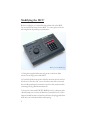
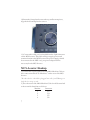
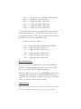
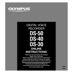
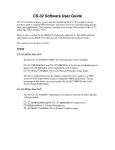
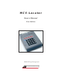
MCS-Locator
Users Manual
First Edition
©2001 JLCooper Incorporated
MCS-Locator
Users Manual
First Edition
MCS-Locator Owners Manual First Edition
Part Number for this manual: 932086
MCS-Locator™ is a trademark of JLCooper Electronics.
All other brand names are the property of their prospective holders.
©2001 JLCooper Incorporated
142 Arena Street, El Segundo, CA 90245
Table of Contents
Introduction .......................................................................... 4
Modifying Your MCS3 .......................................................... 5
MCS Locator Hookup .......................................................... 7
The Front Panel .................................................................... 8
Setup ................................................................................... 10
Time Code Display ............................................................. 10
Pre-Roll ............................................................................... 11
Record Mode ...................................................................... 11
Record Machines ................................................................ 13
Machine Type ..................................................................... 13
Locates ................................................................................ 14
Elapsed Time Calculation ................................................... 16
Specifications...................................................................... 18
Troubleshooting .................................................................. 18
Care and Service ................................................................. 19
Warranty ............................................................................. 20
3
Introduction
Thank you for purchasing the JLCooper MCS-Locator.
We think that you will find it to be an invaluable productivity
tool.
The MCS-Locator is a remote Video Cue Controller designed to
be used in conjunction with the JLCooper MCS3 RS-422/9PIN
jog shuttle control module. It can also be used as a stand alone
device. The MCS-Locator provides “Go-To” and “Edit Preset
Control” for up to four video or audio machines that follow the
Sony P2 protocol. In addition, “Automatic Elapsed Time”
calculations may be performed.
When used in combination with the MCS3 9PIN/RS-422 or
MCS3S 9PIN/RS-422 version, you will have complete Multimachine transport control with a professional jog/shuttle
mechanism and advanced auto-locator controls.
You will need to complete a small modification to the MCS3. in
order to allow communication between the two units. This will
be covered in the first chapter.
Included with your MCS-Locator are the following items:
1
1
1
1
1
MCS3 to MCS-Locator connection cable.......... part #620020
Loccator to VTR connection cable................... part #620021
MCS-ProSeries Joiner Plate ............................. part #710349
5/64” Allen Wrench ........................................ part #933008
Product Registration Card
Please take a moment to fill out your Product Registration Card,
this will allow us to notify you of future updates and products as
they become available.
4
Modifying the MCS3
Before you begin, you should decide which side of the MCSLocator will be mounted to the MCS3. You may place it on the
left or right side depending on preference.
MCS3S joined to MCS-Locator
1) Using the supplied Allen wrench, remove the four Allen
screws on the top panel of the MCS3.
2) Carefully lift the front panel off of the bottom chassis and set
face down off to the side, on a soft surface that will not scratch
the unit. Be particularly careful not ot pull on the attached cable
or damage the Jog/Shuttle mechanism.
3) Located on the small GPCPU-RS422 board, is a Jumper with
“Install Jumper to connect to Machine” printed next to it. This
jumper should be removed and saved. It may be plugged back in
with only one lead attached for safe keeping.
5
Jumper
6-Pin Connector
4) Carefully unplug the 6-pin connector attached to the cable at
the J2 location. Take note of its orientation and remove the strain
relief from the slot on the bottom chassis.
5) Replace this cable with the short cable provided. Be sure to use
the same orientation as the cable you removed.
6) Slide the strain relief of this cable into the slot on the bottom
chasssis.
7) Carefully place the top panel on the bottom chassis.
8) Slide the metal joiner strip between the top and bottom pieces
according to the orientation that you have chosen. Align the
holes on all of the pieces and tighten the four screws.
9) Remove the two Allen screws on the MCS-Locator
appropriate for the orientation you have determined.
6
10) Insert the joiner plate between the top and bottom pieces,
align the holes and replace the screws.
11) Connect the cable you just installed into the 9 pin connector
on the MCS-Locator. This cable will now supply power and
communication to the MCS-Locator. The power supply should
be connected to the MCS3. only, no power adapter will be
necessary for the MCS-Locator.
MCS-Locator Hookup
1) Connect the 25 pin connector of the Multi-Machine Cable to
the connector marked “To Machines” on the rear of the MCSLocator.
No other device should be plugged into this jack! Damage to
both devices may result.
2) The other end of the Multi-Machine Cable should be attached
to the controlled machines as follows:
Machine
1
2
3
4
7
Connector
P3
P4
P5
P6
The Front Panel
The MCS-Locator front panel consists of five main sections:
1) The large eight character Display shows Time Code, User Bits
and setup information.
2) The ten key Numeric Pad is used to input location times,
location numbers and for basic set-up information.
8
3) The six Control Keys are used to start or end control
operations, such as “go-to” or “elapsed time calculations”.
4) The Machine Select area is located in the upper right corner
and consists of four machine select buttons with corresponding
LED designators. These buttons are used to enabled/disabled up
tp four machines which are now being controlled by the MCSLocator and attached MCS3..
All Time Code display information on the MCS-Locator reflects
the state of the lowest numbered enabled machine.
9
5) The Function Select area is located on the left side of the
display and consists of five labeled LED’s and a blue select
button. These buttons are used to select time code, user bits,
preroll and machine type.
10
Setup
Basic decisions that need to to be made during setup include:
• Type of Time Code to be displayed.
• Amount (if any) of PreRoll desired.
• Record Mode
• Type of machine attached.
Time Code Display
The MCS-Locator may display either Control (also know as CTL
or Timer) or Longitudinal (also know as LTC) time code.
To Choose:
1. Press and release the blue Select button repeatedly until the
LED labeled “TC” is lit.
2. Hold the Select button down until the display shows either
“tC-CtL” or “tC-LtC”. This will correspond to Control or
Longitudinal Time Code. While pressing and holding the Select
button, the selection alternates between the two choices. Release
the Select button when the desired choice appears in the display.
3. This selection is remembered and retained internally.
PreRoll
The MCS-Locator may be set to send out all Locate commands
with a user-defined amount of PreRoll from 0 to 9 seconds.
To set your PreRoll:
1. Press and release the blue Select button repeatedly until the
LED labeled “PRE” is lit. The display will show“Pr-x SEC” with
x = number of seconds currently set.
2. By holding down the Select button, the number of seconds
will scroll up to 9, then back to 0. Release at the desired number
of seconds.
11
3. Alternately, while the PreRoll display is in place. the keypad
may be used to enter from 0 to 9 seconds.
4. This selection is remembered and retained internally.
Record Mode
The following four basic Record Modes are supported by the
MCS-Locator:
•Disable- No Edit Preset (Track Arm) may be made, and the
Record button on the MCS3 does not function.
•Crash-No Edit Preset (Track Arm) may be made. Pressing the
Record button on the MCS3 results in a Crash Record message
being sent.
•Assemble- No Edit Preset (Track Arm) may be made. Pressing
the Record button on the MCS3 results in an Assemble record
taking place.
•Insert-Edit Presets (Track Arm) for Video and Audio tracks may
be made. Pressing the record button on the MCS3 results in an
Insert Record taking place.
To Choose the Record Mode:
1. Press and release the Select button until the “REC” LED is lit.
The display will show the current mode.
2. By holding down the Select button, alternate choices will be
shown. Release when the desired choice is shown.
3. While the Record Mode is showing in the display, the keypad
may be used to make Edit Preset changes. This will only function
while in the Insert mode. The keys function as follows:
12
Key 1—> Toggles between Assemble and Insert Modes.
Key 2—> Toggles the Video Edit track.
Key 3—> Toggles the Audio 1 Edit track.
Key 4—> Toggles the Audio 2 Edit track.
Key 5—> Toggles the Audio 3 Edit track.
Key 6—> Toggles the Audio 4 Edit track.
4. The F1 thru F6 buttons on an attached MCS3 may be used to
enable/disable Edit tracks. The MCS-Locator does not need to
be in the Record Mode (“REC” led on) to perform this task, but
the MCS-Locator must be in INSERT mode.
The keys function as follows:
F1—> Toggles between Assemble and Insert Modes.
F2—> Toggles the Video Edit track.
F3—> Toggles the Audio 1 Edit track.
F4—> Toggles the Audio 2 Edit track.
F5—> Toggles the Audio 3 Edit track.
F6—> Toggles the Audio 4 Edit track.
Record Machine(s)
You may designate 0 - 4 machines to be the “Record Machine.”
Machines so designated will be the only one(s) to receive Edit
Preset (Track Arm) and Record/Edit commands.
While the “REC” Led is on, the four MACHINE Leds show the
designated Record Machines. Use the MACHINE buttons to
toggle the state of these LED’s. When you step out of the “REC”
mode, your selection will be saved in memory.
Machine Type
If Edit Preset operations are to be made, the MCS-Locator must
be set to send the correct message. Type 1 is appropriate for
13
most older VTRs, while Type 2 is appropriate for Ampex 1" and
Sony D2 machines. A little experimentation may be necessary to
test which Type you should use. To select:
1. Press and release the Select button until the “Type” LED is lit.
The display will show the current Machine Type.
2. Hold down the Select button until the desired Machine Type is
shown.
3. Alternately, while the “Type” LED is lit, you may press the
Keypad “1” or “2” button to select your Machine Type.
Locates
The MCS-Locator will store 100 Locates within its memory.
These will be stored and retained internally. In addition, there are
seven “quick store” locations available when attached to a MCS3.
The Keypad is used to call up a locate, and to store a specific
locate time.
Note: to perform any Locate operation, the “TC” led must be lit.
To Store a Locate
1. Press the Set Locate button. The display shows “Loc-”.
2. Using the Keypad, enter the two digit Location number that
you wish to store a locate.
3. Press ENTER. The display changes to “—.—.—.—”
4. Using the keypad, enter the desired time. Since the entries
scroll to the left, mistakes may be overwritten by continued
keypad entry.
14
5. Press ENTER. This stores the entered time into the selected
Location. If no keypad entry of time took place, the “current
time” (as reported back from the lowest numbered enabled
machine) will be stored.
To Recall a Locate
1. Using the keypad, enter the two digit Location number you
wish to recall.
2. Press Enter. The recalled time will be sent and will be shown
for two seconds, then the display will revert back to showing the
current time of the lowest numbered enabled machine.
To Enter a ‘manual’ time
1. Press the LOCATE key. The display changes to “—.—.—.—”
2. Using the keypad, enter the desired time.
3. Press ENTER. This entered time will be sent. The display will
continue showing the entered time for two seconds, then revert
back to showing the current time of the lowest numbered
enabled machine. If no time was entered, the time 00:00:00:00
will be sent (minus any PreRoll.)
LAST button
Anytime a Locate is recalled, or if a time is entered manually, it is
stored in an internal Last Register. Pressing the LAST button
sends this time.
CLEAR button
Pressing this will terminate any pending Locate function.
15
Elapsed Time Calculation
The MCS-Locator may be used to automatically calculate elapsed
or running times between either two stored locations or between
the “current” time and a stored location.
Using Two Stored Locations
(Note: it may be easier [i.e. less confusing] if you disable all
machines via the Machine buttons while performing these steps.)
1. Recall the End Location, using steps outlined in Chapter 5
This may be either the main (100 locations) storage, or the Quick
Store storage. If recalling main storage, the ENTER key must be
pushed. If recalling a Quick Store location, ENTER is not
needed.
2. Press the +/- key. This will enter the recalled time into the
calculator memory. The display will dim to indicate a calculation
process going on.
3. Recall the Start Location, using the same steps as in the above
section labeled a).
If recalling Main Storage, the ENTER key must be pushed after
the location is selected. If recalling a Quick Store, the ENTER
key is not needed.
4. The elapsed time is shown in the display. If the time shown is
something like “23.57:45:02” then the locates were entered
backwards, i.e. the first location was a lower time.
5. To restore the display to normal operation, press the ENTER
key again. The display will brighten again.
Using a Stored Location and the “Current Time”
For this to operate, the desired machine must be enabled. Also,
the “Current Time” must be the higher time, i.e. the end of the
segment.
16
1. Press the +/- key. This enters the current time into the
calculator memory. The display will dim to indicate a calculation
process going on.
2. Recall the Start Location. If recalling Main Storage, select the
desired time and press “ENTER”. If recalling a Quick Store, the
ENTER key is not needed.
3. The display will show the elapsed time.
4. To restore the display to normal operation, press the
ENTER again.
17
Technical Information
Specifications
Dimensions.........6.25"x 8.5"x 1.25"
(158.75mm x 215.9mm x 31.75mm)
Weight............... 3 lb (1.4 Kg)
Troubleshooting
If for some reason the MCS-Locator does not give you the
expected results, take a moment to do some investigating.
The most important concept is that you have your Locator
connected properly as outlined on page 5. Take a minute to double
check this setup.
Double check with the manufacturer of the deck you are
controlling to see if an external locator is supported. As long as
your cable connections are setup properly, everything should be
working.
Make sure your VTR is set to “Remote” and not “Local” control.
This will insure that your MCS units are communicating with the
9PIN connector on the back of the VTR.
18
Care and Service
If properly cared for, your MCS-Locator should provide years of
trouble-free performance. Avoid dropping the MCS-Locator or
banging hard on the controls.
Clean with a soft cloth dampened with window cleaner. Do not
allow liquids to get inside the unit.
There are no user-serviceable parts in the MCS-Locator. Please
refer to the really fine print for detailed warranty and service
information.
19
JLCooper Electronics Limited Factory Warranty
JLCooper Electronics (“JLCooper”) warrants this product to be free of defects in materials or
workmanship for a period of 12 months from the date of purchase.
This warranty is non-transferable and the benefits apply to the original owner. Proof of
purchase in the form of an itemized sales receipt is required for warranty coverage.
To receive service under this warranty, customers in the United States should contact the
JLCooper factory at (310) 322-9990 and talk to a service technician.
If necessary, a Return Authorization number may be issued.
For our customers outside the United States, it is recommended that you first contact your
Dealer or Distributor, since they may offer their own service or support policy.
If local support is not obtainable, please send a FAX to JLCooper’s Service Department at
(310) 335-0110, with a detailed description of the service required.
Upon issuance of return authorization, the product should be properly packed and shipped to
Service Department, JLCooper Electronics, 142 Arena St., El Segundo, CA 90245.
Please include the following: copy of the sales receipt, your name and address (no P.O. Boxes,
please), a brief description of the problem, and any other related items discussed with the
service department and considered necessary to evaluate the product or effect a repair. The
return authorization number must be clearly written on the outside of the package.
JLCooper will, without charge for parts or labor, either repair or replace the defective part(s).
Shipping costs are not covered by this warranty.
JLCooper’s normal repair turn around time at the factory is approximately 15 business days,
from receipt of product to shipping. Your actual turn around time will include return
shipping.
Actual turn around time will vary depending upon many factors including the repeatability of
the customer’s reported complaint, the availability of parts required for repair, the availability
of related products needed to evaluate the product if necessary.
Priority services are available. These should be discussed with the service technician at the time
the return authorization is issued.
This warranty provides only the benefits specified and does not cover defects or repairs needed
as result of acts beyond the control of JLCooper including but not limited to: abuse, damage
by accident/negligence, modification, alteration, improper use, unauthorized servicing,
tampering, or failure to operate in accordance with the procedures outlined in the owner’s
manual; nor for acts of God such as flooding, lightning, tornadoes, etc.
THE DURATION OF ANY OTHER WARRANTIES, WHETHER IMPLIED OR
EXPRESS, INCLUDING BUT NOT LIMITED TO THE IMPLIED WARRANTY OF
MERCHANTABILITY, IS LIMITED TO THE DURATION OF THE EXPRESS
WARRANTY HEREIN. JLCOOPER HEREBY EXCLUDES INCIDENTAL AND
CONSEQUENTIAL DAMAGES, INCLUDING BUT NOT LIMITED TO: LOSS OF
TIME, INCONVENIENCE, DELAY IN PERFORMANCE OF THIS WARRANTY, THE
LOSS OF USE OF THE PRODUCT OR COMMERCIAL LOSS, AND FOR BREACH
OF ANY EXPRESS OR IMPLIED WARRANTY OF MERCHANTABILITY,
APPLICABLE TO THIS PRODUCT. JLCOOPER SHALL NOT BE LIABLE FOR
DAMAGES OR LOSS RESULTING FROM THE NEGLIGENT OR INTENTIONAL
ACTS OF THE SHIPPER OR HIS CONTRACT AFFILIATES. THE CUSTOMER
SHOULD CONTACT THE SHIPPER FOR PROPER CLAIMS PROCEDURES IN THE
EVENT OF DAMAGE OR LOSS RESULTING FROM SHIPMENT.
20
©2001 JLCooper Electronics. MCS, Media Control Station, MCS 3, and MCS -Locator are trademarks of JLCooper Incorporated.
Other brand names are the property of their respective holders.
JLCooper Electronics • 142 Arena Street • El Segundo, CA 90245 U.S.A
www.jlcooper.com
P/n 932086
Printed in U.S.A.