1
FaderMaster 4/100
RS-232 Desktop Automation Controller
Users Manual
First Edition
FaderMaster-4/100 RS-232
RS-232 Automation Controller
User’s Manual, First Edition, Part Number 932471
Copyright ©2008
JLCooper Electronics
142 Arena Street
El Segundo, CA 90245 USA
+1 310 322 9990
www.jlcooper.com
All rights reserved worldwide.
FaderMaster 4/100, FaderMaster Professional, FaderMaster Pro,
FaderMaster, MCS-3800, MCS-3400, MCS-3000, MCS-3000x and
MCS-3000 Series are the property of JLCooper Electronics.
All other product names are the property of their respective owners.
2
Table of Contents
Welcome ......................................................................................... 5
Introduction.................................................................................... 6
Features...................................................................................... 6
Interface ..................................................................................... 6
Controls...................................................................................... 7
System Requirements ..................................................................... 9
Installation ..................................................................................... 9
Unpacking.................................................................................. 9
Physical Setup............................................................................ 9
Hookup....................................................................................... 9
Configuration .......................................................................... 10
Operation...................................................................................... 11
Faders....................................................................................... 11
Function Select ........................................................................ 12
Technical Information................................................................. 13
Care and Service .......................................................................... 15
Troubleshooting ........................................................................... 16
Specifications ............................................................................... 17
Electrical:................................................................................. 17
Environmental: ....................................................................... 17
Physical: ................................................................................... 17
Compliance:............................................................................. 17
3
4
Welcome
Thank you for purchasing the FaderMaster 4/100. Continuing in
the tradition of JLCooper’s FaderMaster Professional, the
FaderMaster 4/100 retains the feel and control of high quality;
100mm long throw faders and adds touch sensitive, motorized
automation. The FaderMaster 4/100 delivers this in a compact,
durable desktop package.
Like the FaderMaster Professional, JLCooper’s design philosophy
is to give you the feel and control over your art that technology has
taken away. Modern hardware and software products are loaded
with so many features, but simply lack the tactile user-interface to
quickly and intuitively use these features.
The growing use of computer-based automation has necessitated
the development of a professional mix interface. No longer will
one-fader-at-a-time “mouse mixing” suffice in today’s fast paced,
high profile projects. The faders themselves must have the feel that
the professional video editor or audio engineer demands.
All these qualities have been combined to put you back in control
and give you new opportunities for creative freedom in the studio
or on-stage.
5
Introduction
The FaderMaster 4/100 is a 4-channel automation controller. It
can control computer-based applications such as audio editing,
music production, video editing, animation and scientific
visualization.
Features
• Controls audio, video and animation applications
• Four 100mm touch sensitive, motorized faders
• 8 virtual faders accomplished via bank switching
• Select, Solo, Mute and Aux keys
• Implements all functions of JLCooper MCS-3000x
• Physically compatible with MCS3S and
other MCS-Pro series products in the deep chassis
• Durable, compact all-metal construction
• Single captive cable minimizes footprint
Interface
The FaderMaster 4/100 RS-232 comes with a standard RS-232
interface that connects to any computer that has a RS-232
interface.
6
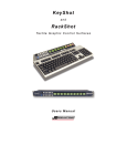
Controls
2
3
1
4
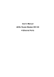
Figure 1 – Control Location
7
1. Faders
Prominently featured on the top panel of the unit are four
100mm, touch sensitive, motorized faders. Because the
faders are motorized, the faders can respond to updates
from your system or software package.
2. Fader Buttons and LEDs
Above the each fader is a button with a corresponding
LED. These buttons and LEDs provide control for various
functions such as SELECT, SOLO, MUTE and AUXiliary.
These buttons are momentary acting. Your system or
computer software controls the LEDs.
3. Function Select Buttons
To the left side are four buttons, which select the
functionality of the buttons above the faders.
4. Inc / Dec Buttons
Changes the fader bank. The FaderMaster 4/100 internally
keeps track of 8 fader channels. However, since the
FaderMaster 4/100 only has 4 physical faders, the
INC/DEC buttons allow the user to select the four channels
that the unit controls at any given time. DEC selects
channels 1,2,3 & 4, which is the default after power is
applied, while INC selects channels 5, 6, 7 & 8.
8
System Requirements
Any computer, PC or Macintosh with a RS-232 interface.
Installation
Unpacking
When unpacking the unit please keep the original packaging in the
event the unit needs to be shipped.
The unit is packed with the following items:
FaderMaster 4/100
Universal Power Supply
This Users Manual
Physical Setup
• Mount the unit on a solid surface away from dust or
moisture.
• Connect the provided power supply to the unit.
• Connect the power supply to a proper power outlet.
• Connect the FaderMaster 4/100 to your system as outlined
below.
Hookup
The FaderMaster 4/100 RS-232 connects to a RS-232 port in your
computer. It can connect to a computer such as a Mac or PC.
9
Configuration
Macintosh
To install your FaderMaster 4/100 RS-232 on your Mac, you will
need a USB to RS-232 adapter.
Windows
To install your FaderMaster 4/100 RS-232 on your PC, you only
need to plug your unit into a RS-232 port on your PC. You may
need a USB to RS-232 adapter.
10
Operation
Faders
Since there are only 4 physical faders, only 4 faders can be
manipulated and shown at any time. The use of all 8 faders is
accomplished through “bank switching”. The faders are arranged
in two groups of 4 faders. The Inc/Dec button selects the bank to
make active. When the unit is first powered on, Bank 1 (faders 14) is active. When the INC button is pressed, Bank 2 (faders 5-8)
is active. Bank 1 can be selected by pressing the DEC button.
The FaderMaster 4/100 internally keeps track of all 8 faders. For
example, if the INC button is pressed, the FaderMaster 4/100 will
remember the settings of Faders 1-4. Pressing the DEC button will
restore the faders to their original positions.
Additionally, if the computer made updates to the fader position,
those positions would be remember even if they were part of a
bank that was not currently selected.
This also holds true for the LEDs above the faders. The
FaderMaster 4/100 will remember the settings of the LEDs when
the banks are changed.
11
Function Select
The Fader buttons can produce various actions in your application.
Typically, the Fader buttons can be set to perform a SELECT,
SOLO, MUTE or any other command that your software package
might use.
The SELECT function normally performs a track select or track
arm. Pressing this button selects the track for recording or editing.
The MUTE function is straightforward. This usually mutes the
selected track during playback or record.
The SOLO function typically mutes all other tracks except the
selected tracks.
The AUX function is dependent on the software package you are
using. The software manufacturer can use this button to
implement any function. Please consult your documentation.
12
Technical Information
Communication
Communications with the RS-232 unit follows the MIDI
specification.
Faders
When a fader is moved, the FaderMaster 4/100 sends the following
message:
Bnh 07h 0xxxxxxxx 27h 0y000000
n
xxxxxxx
y
0 to 7, corresponding to faders 1 thru 8
Most significant 7 bits of fader position
Least significant bit of fader position.
For example, Fader #2 moved to full scale (FFh), would yield:
B1h 07h 7Fh 27h 40h
Conversely, to command a fader to move to a specified position,
the same message format is used.
Sending the least significant bit is optional. For example, the
commands:
B3h 07h 39h
and
B3h 07h 39h 27h 00h
are interpreted identically.
13
Note: Since there are only four physical faders, reception
of a fader position command for a fader not selected on the
current bank will be stored internally until the operator has
made a bank change.
Touch
When a fader knob is touched or released, the FaderMaster 4/100
sends the following message:
Bnh 4Ah 0xxxxxxxx
n
xxxxxxx
0 to 7, corresponding to faders 1 thru 8
7Fh when the fader is touched and
00h when the fader is released
Buttons/LEDs:
The function select buttons determine the behavior of the buttons
above the faders. In the FaderMaster 4/100, there are 4 buttons
that allow the user to directly select the function for the buttons
above the faders. An LED indicates the function selected for the
buttons above the faders.
When a button above the fader is touched or released, the
FaderMaster 4/100 sends the following message:
Bnh 0xxxxxxx 0yyyyyyy
n
xxxxxxx
yyyyyyy
0 to 7, corresponding to faders 1 thru 8
button function (see table on next page)
7Fh when the button is pressed and
00h when the button is released
14
Mute
Solo
Aux
Select
46h
47h
48h
49h
As with the faders, the same message format is used illuminate the
LEDs above the faders.
Note: Since there are only four physical faders, reception
of a LED illuminate command for a fader not selected on
the current bank will be stored internally until the operator
has made a bank change.
Care and Service
While the FaderMaster 4/100 was designed to deliver years of
trouble free use, there are some things to keep in mind while using
this product:
•
•
•
•
•
•
•
•
•
•
•
Use only the provided power supply and grounded power
cord
Plug the power supply into a grounded power outlet
Do not use unit if power cord is frayed or damaged
Use the unit indoors
Do not use the unit if it is wet or in a damp environment
Do not use if a foreign object or liquid has fallen into the
unit.
Do not use if the unit has been damaged
Do not clean or lubricate the faders
Use only a damp cloth to clean the unit
Unplug the unit when not in use
Do not use the unit during an electrical storm
15
Troubleshooting
The FaderMaster 4/100 is a rather straightforward device that does
not require any programming to setup. The unit works right out of
the box. Try these steps before calling a Customer Service Rep.
None of the Function Select
LED illuminate.
Faders stick all the way up or
down.
Unit is not recognized by
computer.
Application does not respond to
faders.
Faders do not respond to
application.
Application does not respond to
buttons.
Check power supply
Discontinue use immediately
and contact service center.
Verify that the MIDI port
drivers are installed.
Verify that unit is plugged into
correct RS-232 port
Verify that the computer shows
that the FaderMaster 4/100
device is installed.
Verify that fader automation is
set to WRITE.
Verify that application supports
external faders.
Verify that application is
configured to send fader
messages.
Verify that fader automation is
set to READ.
Verify that driver and MCSEditor is installed.
Verify that MCS-Editor keyset
is configured for application.
Verify that buttons map to
functions in application.
16
Specifications
Electrical:
Operating voltage
Signal Interface
Environmental:
Operating Temperature
Storage Temperature
Operating Humidity
Storage Humidity
Physical:
Unit Dimensions
Shipping Dimensions
Unit Weight
Shipping Weight
Compliance:
WEEE Compliant
IEC
PSE
UL
100 – 240 Volts AC, 50 – 60 Hz,
0.45 Amps maximum
RS-232
2 meter attached cable
A type male connector
2.1mm coaxial power connector
+10°C to +40°C
+0°C to +50°C
20% to 80% (noncondensing)
10% to 90% (noncondensing)
34mm L x 32mm W x 28.4mm H /
8½” L x 6½” W x 3” H
39.7mm L x 33.7mm W x 32mm H /
14¼” L x 8¼” W x 6½” H
1.48kg. / 3.25lbs.
2.64kg. / 5.80lbs.
EN-55013, EN-55020
following the provisions of
89 / 336 / EEC, EMC Directive.
JET 1362 - 61010 - 2008 - 2
Listed E202402
17
JLCooper Electronics Limited Factory Warranty
JLCooper Electronics ("JLCooper") warrants this product to be free of defects in
materials or workmanship for a period of 12 months from the date of purchase. This
warranty is non-transferable and the benefits apply to the original owner. Proof of
purchase in the form of an itemized sales receipt is required for warranty coverage. To
receive service under this warranty, customers in the United States should contact the
JLCooper factory at +1 310 322 9990 and speak with a service technician. If necessary, a
Return Authorization number may be issued. For our customers outside the United States,
it is recommended that you first contact your Dealer or Distributor, since they may offer
their own service or support policy. If local support is not obtainable, please send a FAX
to JLCooper's Service Department at +1 310 335 0110 with a detailed description of the
service required. Upon issuance of return authorization, the product should be properly
packed and shipped to: Service Department, JLCooper Electronics, 142 Arena Street, El
Segundo, CA 90245. Please include the following: copy of the sales receipt, your name
and address (no P.O. Boxes, please), a brief description of the problem, and any other
related items discussed with the service department and considered necessary to evaluate
the product or effect a repair. The return authorization number must be clearly written on
the outside of the package. JLCooper will at its option, without charge for parts or labor,
either repair or replace the defective part(s). Shipping costs are not covered by this
warranty. JLCooper's normal repair turn around time at the factory is approximately 15
business days from receipt of product to shipping. Your actual turn around time will
include return shipping. Actual turn around time will vary depending upon many factors
including the repeatability of the customer's reported complaint, the availability of parts
required for repair, the availability of related products needed to evaluate the product if
necessary. Priority services are available at additional cost. These should be discussed
with the service technician at the time the return authorization is issued.This warranty
provides only the benefits specified and does not cover defects or repairs needed as result
of acts beyond the control of JLCooper including but not limited to: abuse, damage by
accident/negligence, modification, alteration, improper use, unauthorized servicing,
tampering, or failure to operate in accordance with the procedures outlined in the owner's
manual; nor for natural or man-made events such as, but not limited to flooding,
lightning, tornadoes, earthquake, fire, civil unrest, war, etc.
THE DURATION OF ANY OTHER WARRANTIES, WHETHER IMPLIED OR
EXPRESS, INCLUDING BUT NOT LIMITED TO THE IMPLIED WARRANTY OF
MERCHANTABILITY, IS LIMITED TO THE DURATION OF THE EXPRESS
WARRANTY HEREIN. JLCOOPER HEREBY EXCLUDES INCIDENTAL AND
CONSEQUENTIAL DAMAGES, INCLUDING BUT NOT LIMITED TO: LOSS OF
TIME, INCONVENIENCE, DELAY IN PERFORMANCE OF THIS WARRANTY,
THE LOSS OF USE OF THE PRODUCT OR COMMERCIAL LOSS, AND FOR
BREACH OF ANY EXPRESS OR IMPLIED WARRANTY OF MERCHANTABILITY APPLICABLE TO THIS PRODUCT. JLCOOPER SHALL NOT BE LIABLE
FOR DAMAGES OR LOSS RESULTING FROM THE NEGLIGENT OR
INTENTIONAL ACTS OF THE SHIPPER OR HIS CONTRACT AFFILIATES. THE
CUSTOMER SHOULD CONTACT THE SHIPPER FOR PROPER CLAIMS
PROCEDURES IN THE EVENT OF DAMAGE OR LOSS RESULTING FROM
SHIPMENT. THIS WARRANTY SHALL BE GOVERENED BY THE LAWS OF THE
STATE OF CALIFORNIA.
18