1
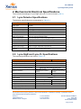
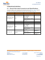
User Manual Lynx-GigE and Lynx-CL 5. Electrical Interface 5.1. General Overview Connectors and Specifications Connect all cables to the connectors at the rear side (see also (Ref 2)). Table 5-1lists the connector and interface specifications overview for the Lynx-GigE and Lynx-CL. Interface XSL-GigE Input power (12V DC) Trigger (either Triggerin or Trigger-out!) Ethernet XSL-CL Input power (12V DC) Trigger (either Triggerin or Trigger-out!) Mini-camera link Connector Specification Hirose HR10-7R-4SA(73) SMA RJ45 connector Hirose HR10-7R-4SA(73) SMA CONN SDR 26POS VERT RECEPT 12V ±10% Trigger in: VIN,L = 0.8V Max. VIN,H = 2V Min. VIN,MAX = 30V Internal Pull-down: R = 10kΩ Trigger out: VHIGH = 3.3V ±10% VLOW = 0V GigE standard 12V ±10% Trigger in: VIN,L = 0.8V Max. VIN,H = 2V Min. VIN,MAX = 30V Internal Pull-down: R = 10kΩ Trigger out: VHIGH = 3.3V ±10% VLOW = 0V Serial control: 115200 baud, 8n1 Levels: RS-644 Image acquisition: CL Camera Protocol GigE Vision XSP Protocol: see (Ref 1) CL Base protocol/ 1 TAP for image acquisition Table 5-1 Electrical interface specifications for Lynx-GigE and Lynx-CL cameras Company confidential. This document is the property of Xenics. It may not be reproduced – completely or partially – or passed to a third party without written permission from Xenics. Xenics nv Ambachtenlaan 44 BE-3001 Leuven Belgium T +32 16 38 99 00 F +32 16 38 99 01 www.xenics.com Doc Ref: ENG-2012-UMN018 Issue: 003 Date: 31/03/2014 XF-104_02/20-01-2012 Page 21 of 27