1
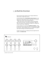
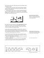
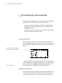
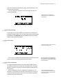
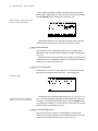
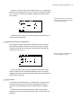
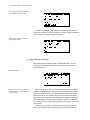
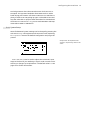
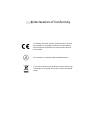
USER MANUAL
E-RM ERFINDUNGSBÜRO
Copyright © 2015
e -r m e r fin du ng sbür o - ht t p:/w w w.e-rm .d e
E-RM Erfindungsbüro Rest & Maier GbR
Wikingerufer 7
10555 Berlin
Germany
PRELIMINARY VERSIONJuly 2015
Contents
1 The Purpose of the Multiclock
7
2 Machine Overview
8
3 Configuring the machine
3.1 Clock Source . . . . . . . . . . . . . . .
3.2 Time Signature . . . . . . . . . . . . .
3.3 Channel Setup . . . . . . . . . . . . . .
3.3.1 Shift Range . . . . . . . . . . .
3.3.2 Offset Calibration . . . . . . .
3.3.3 Channel Mode . . . . . . . . .
3.3.4 LFO Configuration . . . . . . .
3.3.5 Analog Configuration . . . . .
3.3.6 Midi Controller Configuration
3.3.7 Presets . . . . . . . . . . . . . .
3.4 Advanced Settings . . . . . . . . . . .
3.4.1 System Setup . . . . . . . . . .
.
.
.
.
.
.
.
.
.
.
.
.
10
10
10
11
11
11
12
12
12
13
13
14
15
4 Using Audio Sync
4.1 Plugin . . . . . . . . . . . . . . . . . . . . . . . . . . . . .
4.2 Sync Track . . . . . . . . . . . . . . . . . . . . . . . . . .
16
16
16
5 Using USB MIDI
17
6 Tips and Limitations
6.1 Nice to know . . . . . . . . . . . . . . . . . . . . . . . . .
6.2 Audio Sync . . . . . . . . . . . . . . . . . . . . . . . . . .
17
17
18
7 Updating the System Software
18
8 Declaration of Conformity
20
9 Contact
21
.
.
.
.
.
.
.
.
.
.
.
.
.
.
.
.
.
.
.
.
.
.
.
.
.
.
.
.
.
.
.
.
.
.
.
.
.
.
.
.
.
.
.
.
.
.
.
.
.
.
.
.
.
.
.
.
.
.
.
.
.
.
.
.
.
.
.
.
.
.
.
.
.
.
.
.
.
.
.
.
.
.
.
.
.
.
.
.
.
.
.
.
.
.
.
.
.
.
.
.
.
.
.
.
.
.
.
.
Simply play together.
Introduction
Hello Stranger!
Congratulations for purchasing your multiclock. You have just
purchased an avant-garde machine: you are now able to solve sync
and timing issues in the studio and on stage once and for all.
This multi-format sync box builds a bridge between DAWs and
external MIDI, DIN/sync24 and analog modular gear. It allows tight
integration of external instruments into your digital production
workflow without having to worry about timing.
Also as a standalone master clock generator for hardware-only
setups it cuts a dash. Start shifting your clocks, start shuffling the
beat, we are sure you will enter unknown territories.
Please read this manual carefully and follow the advice to be rewarded from the beginning with a great and powerful tool. And be
assured, the multiclock is a game changer!
Have fun and start making music,
The team of E-RM
1 The Purpose of the Multiclock
The multiclock is a multi-format sync box which is built to overcome
all well known problems with tight synchronization of external
sequencers, drummachines, arpeggiators and other external gear
with each other and especially in the workflow with a DAW.
The key feature of the multiclock is it's ability to derive a variety
of sync signals from a special Audio Sync track instead of using for
example a MIDI Clock signal.
With this technique, the multiclock is able to generate MIDI
Clock, DIN/sync24 and analog modular clock signals to sync your
slaves with a jitter as low as ±20 μs. This finally ensures seamless
integration of all of your external instruments with your computer.
The second important feature of the multiclock is it's ability to
shift all output clock channels against each other and relative to
the master clock back and forth in realtime. Up to ±300 ms of shift
range ensure easy compensation of machine delay, audio buffer
latencies and leave more than enough headroom to shift just to
get the groove.
The multiclock is not built to be syncronized by a master DAW using
MIDI or USB MIDI, nor does it correct your MIDI Note timing; it
probably also can not fly to the moon.
But instead you can finally start bending time, play with the
phase of your sounds and adjust microtiming of your arrangements. Let's start today, it's a lot of fun!
20.83 μs is the length of one sample at
an audio sampling frequency of 48 kHz
2 Machine Overview
The front panel of the multiclock can be roughly divided into a
real-time and a configuration section.
On the left half, there are four identical channel stripes for realtime control of each output channel. They consist of a shift and a
shuffle knob, a status led and a start/stop button.
Shift knobs feature a center detent to easily set the channel
offset to the zero position. The status leds light up in different
colours to indicate running mode during playback or highlight the
current channel under configuration.
On the right half, you can find the configuration display, a rotary
encoder with click to navigate the menus, a function key and a BPM
led. Moreover, global start/stop buttons are available for playback
control when running on the internal masterclock.
During normal operation, the display presents all significant information on the homescreen.
multiclock front panel overview.
You see the clock source, time signature and current BPM on the
right part of screen.
On the left part is one line for each output channel to display
channel mode or additional information like shift offset, shuffle
amount or LFO waveform.
On the bottom of the screen is a button section which allows
you to change the global machine configuration. Use the select
menu button to toggle the cursor between the virtual buttons and
the upper main part of the screen.
Example Homescreen. Notice the
different Channel Modes shown here:
Channel 1 is configured as LFO, Channel
2+3 work in sync mode and Channel 4 is
used as a MIDI controller.
The rear panel of the multiclock provides connectivity and input
for the power supply. It can also be divided into two sections:
inputs on one side, outputs on the other. DC input and a power
switch are located on the rightmost edge.
Syncronisation inputs are available in the form of a ¼" jack for
Audio Sync and a DIN socket for MIDI, sync24 and analog modular
sync. Audio Sync can be fed as a balanced or unbalanced signal but
is internally treated unbalanced in both cases.
On the left, there are four DIN sockets for each output. Any of
them can provide MIDI, sync24 and analog modular sync, depending on the channel settings in the menu.
Channel 1 additionally has a ¼" TRS output jack to provide analog clock or analog LFO.
Channel settings can be reached by holding the set channel
button and pressing the button of the respective channel.
Modular Synth connectivity is easily
accomplished by using a E-RM modular
whip to convert from all DIN sockets to
2 mini jacks for clock & run signals.
Tip = Clock/LFO, Ring = Start
multiclock connector overview.
10 m u l tic lo c k - u ser ma nu al
3 Configuring the machine
Configuring the settings of your multiclock is as easy as following
the menu on the screen if you keep two things in mind:
• The screen is always divided into a main and a bottom section.
To toggle the cursor between both sections, simply push the
select menu button.
• Turn the encoder to move the cursor or change settings. Click it
to select an option or submit a change.
3.1 Clock Source
Before using the multiclock in your setup, probably the most important setting is the selection of the clock source. You can reach
the configuration page from the homescreen by selecting the SRC
button.
Clock source selection. USB MIDI
channel can be chosen after selection.
www.e-rm.de/support
Choose between several input formats or use the internal masterclock generator. The recommended way to syncronize external
gear to a DAW is using Audio In and the plugin provided on our
website. Please refer to page 16 for further instructions.
3.2 Time Signature
To be able to start slaves always in sync with the downbeat of the
next bar, the multiclock needs to know which time signature you
are playing in. Select the T.SIG button from the homescreen to
co n fi g u r i n g t h e m a c h i n e 11
get to the respective configuration page. Set all machines in your
setup to the same value.
You can change the signature from 3/8 to 32/8, changes are
saved automatically.
Configuration of Time Signature.
Values are shown in reduced fraction
form beneath.
3.3 Channel Setup
All changes concerning the different channels are configured on
the Channel Setup pages. You can reach each channel's setup page
by holding the set channel button and additionally pressing the
button of the respective channel.
3.3.1 Shift Range
Channel Setup Page. Notice the preset
name on top of the screen.
Shift Range configures the min/max value of shift amount that
you can reach by turning the shift knob to the limits.
All knob ranges are internally divided
into 1000 steps. You should always fit
the shift range to your usecase to gain
best performance.
3.3.2 Offset Calibration
To compensate audio delay of connected slaves, buffer latency
of software monitoring or other sources which cause a constant
offset to a channel, you can set a constant offset as the channel's
zero position.
Offset calibration process is initiated by selecting Offset in
the menu. You are asked to start the clock source first. If you are
using the internal generator, please press the global play button,
otherwise start the master clock.
It is recommended to program a
simple percussive sound on every full
note of the machines involved in the
calibration process.
12 m u l tic lo c k - u ser ma nu al
First, adjust the offset roughly until both sounds play at the
same instant. Afterwards you can get into microtiming by holding
the set channel button and adjust in steps of 20 μs.
Offset Calibration. Used to set the zero
position in time for each channel.
Change the value until you are happy with the result. Stop the
master clock and submit your value by clicking the encoder.
3.3.3 Channel Mode
Each channel can be configured under Chn Mode to emit either
MIDI Clock (MIDI), DIN Sync/sync24 (DIN) or analog modular clock
(Analog).
Unused channels can further be used as a MIDI controller (Ctrl).
A special function is available on Channel 1 which features an analog LFO on it's TRS output jack (LFO).
3.3.4 LFO Configuration
When Chn Mode is set to LFO on Channel 1, a syncronized analog
LFO signal is emitted on the tip of the ¼" TRS output jack.
LFO Configuration.
The LFO is obviously also completely
shiftable in time. Try it, you will like it!
The waveform can be selected between Saw Up, Saw Down, Sine,
Pulse and Random and is displayed on the homescreen. The LFO
Frequency is changed during performance with the shuffle knob.
It is either free running (free) and reset on every new bar or quantized to fit the current tempo (quant).
3.3.5 Analog Configuration
Due to an enormous variety of clock polarities, start/stop behaviour and necessary dividers in the modular world, you can fully
configure all settings when Chn Mode is set to Analog.
co n fi g u r i n g t h e m a c h i n e 13
START Mode can be set to emit a trigger pulse (Trig.), optionally
skip the first clock pulse after start (Trig sk) or simply act as a gate
(Gate). Be sure to check your modular sequencers manual of you
are in doubt.
Analog Configuration. This mode can
also be used with DIN Sync instruments
to implement clock dividers.
Dividers are fun, thus you can set any integer divider between 1
and 96 on the analog clock.
3.3.6 Midi Controller Configuration
If you happen to have unused clock channels on your multiclock
and need a basic MIDI Controller for one of your synths, simply
configure the knobs to emit MIDI Control Change commands by
setting Chn Mode to Ctrl.
Midi CC Configuration. Messages can
be routed to different outputs.
You can configure the output port, MIDI Channel and control
change number. Knobs send values between 0 and 127, buttons
toggle between the min and max value, button state is indicated by
the channel's status led.
3.3.7 Presets
To maintain channel settings for your different instruments, they
can be saved as presets once they are configured. Presets are
based on a per channel basis, not as a whole machine configuration.
Simply select the virtual SAVE button on the Channel Setup
page, choose a preset number and name them. 30 preset cells are
available.
14 m u l tic lo c k - u ser ma nu al
Save Presets. Numbers and characters
are accessible in an infinite loop.
Presets are loaded by selecting the LOAD button. Choose the
preset you need and click the encoder to load it. Presets containing
LFO settings can only be loaded on Channel 1.
Load Presets. 'empty Name' loads a
factory default preset.
3.4 Advanced Settings
By hitting the virtual CONF button on the homescreen, you can
configure some advanced settings which affect the multiclock's
general behaviour.
Advanced Settings.
Please note: the Offset Parameter is
saved seperatly in the channel presets
for both modes!
With Machine Mode you can choose between NEG/POS and POS.
The former allows you to shift sync signals back and forth with respect to the masterclock. This implies one bar forerun before all
slaves start when you initiate the master clock. The latter mode
skips this one bar and starts everything as you hit play on the master in exchange to allow only positive delays. There is a nice trick
for sme cases to circumvent this behaviour, check page 17 for more
information.
The Free Wheel option is implemented for stage. If you set it
to On, the multiclock will automatically turn on it's internal mas-
co n fi g u r i n g t h e m a c h i n e 15
terclock generator when the external master clock source is interrupted. This prevents headache when DAWs crash or cables
break during performance. All slaves continue to run and there is
plenty of time to set everything up again. To be able to start and
stop the multiclock on purpose when Free Wheel is activated and
Clock Source is set to Audio In, you can send MIDI Start and Stop
commands to MIDI or USB MIDI In.
3.4.1 System Setup
Some fundamental system settings can be changed by entering the
sub-menu Setup. LCD brightness and contrast are self explaining.
Factory Reset restores the default configuration and purges all
presets.
Setup Screen. Be careful with 'LCD
Contrast'. The pixels may vanish on the
limits!
Audio Threshold can be used to adjust the multiclock's input
stage to the level of your Audio Sync signal. Under normal circumstances, no changes are required here - the default value is 7. See
page 16 for further information.
4 Using Audio Sync
To synchronize the multiclock to a master DAW, you should always
use the Audio Input and avoid MIDI or USB MIDI under all circumstances.
This requires in all cases the following prerequisites:
• A computer running your favourite DAW
Both balanced and unbalanced outputs work fine.
• 1 mono audio output channel of the soundcard, exclusively
connected to the multiclock
• The ability to load our VST/AU plugin or to generate a sync track
with a special sample provided on our website
You can also use the methods described here to sync the multiclock
to hardware samplers while avoiding MIDI Clock.
4.1 Plugin
The easiest way to set everything up is to use our VST/AU plugin:
www.e-rm.de/support
• Get the plugin for your operating system on our website and
install it according to the instructions of your DAW
• Pull it on an empty track in your DAW
• The plugin interface is simple, the only thing you can configure is
time signature. Open the plugin window and set it to the same
value that you have configured for all other machines
Please take care not to send any other
audio to this channel, this will render
everything useless.
• Assign the track's audio output to the soundcard channel you
have connected your multiclock to and set the fader initially to
0 dB
Here you go, that's it. Set the multiclock to accept Audio In according to Section 3.1 and hit play on your DAW.
The BPM led on the multiclock starts to flash and the display
shows the actual tempo.
4.2 Sync Track
Another simple method to syncronize the multiclock to DAWs and
hardware samplers is to use a sync track. All you need is one mono
audio output, a syncronization sample and a way to program a
loop.
• Get the sync sample from our website and load it onto your
desired harware sampler or DAW.
• Create a new track and assign the track's audio output to the
audio channel you have connected your multiclock to. Set the
output level initially to 0 dB
• Now program a loop to play the sync sample on 24 notes per
beat
Set the multiclock to accept Audio In according to Section 3.1 and
hit play on the master you have just programmed.
The BPM led on the multiclock starts to flash and the display
shows the actual tempo.
5 Using USB MIDI
If your multiclock has a USB module installed, you are able to add
other Midi commands from a DAW to the timing accurate clock
streams.
There is one virtual USB Midi output for every physical channel.
Midi data transmitted to one of them get's merged with priority
for the clock ticks into the Midi clock stream of the respective
channel.
You can also use USB Midi Output 1 as a start/stop remote of the
multiclock while running in Free Wheel mode.
6 Tips and Limitations
This section can be considered the FAQ part of this manual. It is
both a random compilation of tips & tricks and useful advice to
cure little ailments.
6.1 Nice to know
• If you are playing at a fixed tempo and want to be able to shift a
channel by a 16th note, simply calculate the duration of a 16th
24 notes per beat = 24 ppq =
64th note triplets = 64T
note and set the maximum shift range to this value. The formula
is:
15000
Shift Range =
BPM
• An huge number of multiclocks can be fed paralell by the same
Audio Clock source. Simply use a passive audio spitter to feed
the signal to as many clocks as you need
• You can set machine mode on the multiclock to POS and keep
the ability to perform negative shifts using Audio Sync if you
are able to configure a negative track delay on the Plugin or
Sync Track audio output on the DAW. Example: Set the track
delay to -100 ms on the DAW and the shift range of the channels
to +200 ms. The zero position in time on the multiclock is at
+100 ms then and you can move back and forth from there.
• DIN Sync and shuffle at the maximum tempo of 300 BPM can
cause some old machines to stutter - they are old, please be a bit
tolerant about their quirks
6.2 Audio Sync
• The displayed tempo on the multiclock might be subject to
roundoff deviation on the last decimal place. This does not
affect syncronization at all
• You can also use a percussive sound at 24 ppq or an analog LFO
as the master clock. Please make sure that the positive pulse
width is at least 1.5 ms, don't exceed 300 BPM
• If the display shows ERR instead of the actual tempo or the BPM
led flashes irregularly, please check your wiring. Ground loops
and exceptionally high noise floor might distort the sync signal
as well as excessive levels above 10 dBu
If you have ensured proper wiring, you can adjust both the Audio
Threshold of the multiclock (p. 14) or audio level on the soundcard.
7 Updating the System Software
To update the system software of your multiclock, it is vital to
ensure steady power supply for at least 10 minutes.
Then follow the instructions below to update the software using
the internal MIDI Sysex bootloader:
up d a t i n g t h e s y s te m s o f t w a r e 19
• Make sure you have a computer and a proper way to replay MIDI
Sysex files
• Download the latest system software from our website and load
it into your sysex tool
• Hold down the leftmost (channel 1) and rightmost (. ) button
while turning on your multiclock to enter the bootloader
• Now connect your sysex tool with the multiclock:
– for the classic version, simply connect MIDI Out from your
computer to MIDI In on the machine
– for the USB version, use a USB cable to connect your computer and the machine
• Configure the correct MIDI output in your sysex tool. USB versions take software updates on USB Midi Output 1
• Start the transmission according to the manual of your sysex
tool. The bootloader on the multiclock will indicate the progress
and start the new software when it is fully loaded
There are Sysex dumpers for all operating systems available as freeware on
the internet: SysEx Librarian, MIDI-OX
or Simple Sysexxer
8 Declaration of Conformity
It is hereby confirmed, that the multiclock meets all rules
and regulations regarding EU-directive 2004/108/EG for
electromagnetic compliance to protect humans and the
environment.
The multiclock is compliant with the RoHS directive.
If you wish to dispose your multiclock, please contact your
local dealer for recycling. Do not put it in your household
waste.
9 Contact
We, that is E-RM Erfindungsbüro, make the multiclock to meet our
own high expectations on value and functionality of a product.
If you have any questions or suggestions, do not hesitate to contact us.
E-RM Erfindungsbüro Rest & Maier GbR
[email protected]
www.e-rm.de