1
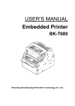
Confidential SNBC User Manual BK-T080 Kiosk Printer V1.0 SHANDONG NEW BEIYANG INFORMATION TECHNOLOGY CO., LTD BK-T080 user MANUAL DECLARATION This manual applies to BK-T080 series embedded printer, and the information in this document is subject to change without notice. Shandong New Beiyang Info-Tech Co., Ltd. (hereinafter referred to as “SNBC”) reserves the right to improve products as new technology, components, software, and firmware. If users need the further data about these products, please feel free to contact SNBC or our distributors. No part of this document may be reproduced or transmitted in any form or by any means, electronic or mechanical, for any purpose without the express written permission of SNBC. Copyright This manual was published in 2007 with copyright belonging to SNBC. Version: 1.0 Trademark Our registered trademark is Marks means: Warning Items shall be strictly followed to avoid injury or damage to body and equipment Notice Items with important information and -1- BK-T080 user MANUAL prompts for operating the printer Heating Calorific parts, don’t touch. Warning Don’t touch and avoid damage due to static electricity. The quality control system of SNBC has been approved by the following certification DNV ISO9001: 2000 The environmental management system of SNBC has been approved by the following certification: DNV ISO14001:2004 -2- BK-T080 user MANUAL Revision History Date Version Description Author 3-30-2007 V1.0 First version Mr. Zhang Zhengmin Mr. Yang Xiangang -3- BK-T080 user MANUAL Safety Instructions Before installing and using the printer, please read the following items carefully 1) Install the printer at a flat and stable place. 2) Reserve adequate space around the printer so that the operation and maintenance can be performed conveniently. 3) Keep the printer far away from water source. 4) Do not use or store the printer in a place exposed to heat of fire, moisture and serious pollution and do not expose the printer to direct sunlight, strong light and heater. 5) Do not place the printer in a place exposed to vibration and impact. 6) No dew condensation is allowed with the printer. In case of such condensation, do not turn on the power until it has completely gone away. 7) Connect the AC power adapter to an appropriate grounding socket. Avoid sharing one electrical socket with large power motors and other devices that may cause the fluctuation of voltage. 8) Disconnect the DC adapter when the printer is deemed to idle for a long time. 9) Don’t spill water or other electric materials into the printer. If this case happens, turn off the power immediately. 10) Do not allow the printer to print when there is no paper installed, otherwise the print head and platen roller will be damaged. -4- BK-T080 user MANUAL 11) To ensure printing quality and products lifetime, use recommended paper or its equivalent. 12) Turn off the power when connecting or disconnecting interfaces connectors to avoid damages to control board. 13) Set the printing darkness in a lower grade as long as the print quality is acceptable. This will help to keep the print head durable. 14) Do not disassemble the printer without permission of a technician, even for repairing purpose. 15) Keep this manual carefully for reference. -5- BK-T080 user MANUAL CONTENT 1. SUMMARY......................................................................... 9 1.1 Brief introduction ........................................................................9 1.2 Main features............................................................................10 2. MAIN TECHNICAL INDEX............................................... 12 2.1 Technical specification .............................................................12 2.2 Paper Specification ..................................................................14 3. STRUCTURE AND FUNCTIONS..................................... 19 3.1 Appearance ..............................................................................19 3.2 External dimension...................................................................21 3.2.1 Overall size of the printer.......................................................21 3.2.2 Printing unit size ....................................................................24 3.3 Print unit and controlling parts ..................................................25 3.3.1 Exterior of print unit and controlling parts ..............................25 3.3.2 Print unit explanation.............................................................26 3.4 Presenter..................................................................................27 3.5 Paper holder.............................................................................29 3.6 Interface ...................................................................................30 4. INSTALLATION AND SUGGESTION ............................. 31 4.1 Unpacking ................................................................................31 4.2 Adjusting paper near end sensor..............................................31 4.2.1 Detection range of paper near end sensor ............................31 4.2.2 Adjusting paper near end sensor...........................................33 4.3 Connecting the grounding wire.................................................34 -6- BK-T080 user MANUAL 4.4 Connecting the AC power adapter ...........................................35 4.5 Connecting interface cable .......................................................36 4.6 Assembling and feeding paper roll ...........................................37 4.6.1 Assembling paper..................................................................37 4.6.2 Loading paper .......................................................................38 4.7 Installing the printer ..................................................................40 4.7.1 Installation notice...................................................................40 4.7.2 Keep space for printer installation .........................................40 4.8 Installing printer driver ..............................................................49 4.8.1 Typical installation .................................................................49 4.8.2 Advanced installation ............................................................52 4.8.3 USB printer driver..................................................................55 5. ROUTINE MAINTENANCES ........................................... 60 5.1 Cleaning Print head..................................................................60 5.2 Cleaning sensor .......................................................................62 5.2.1 Cleaning paper end sensor ...................................................62 5.2.2 Cleaning paper load sensor...................................................66 5.2.3 Cleaning retraction sensor.....................................................68 5.2.4 Cleaning paper out sensor ....................................................69 5.3 Cleaning the platen ..................................................................71 5.4 Manual resetting cutter.............................................................72 5.5 Manual removal of the jammed paper ......................................73 5.6 Remove the jammed paper of presenter ..................................74 6. INTERFACE SIGNAL ...................................................... 75 6.1 RS-232 Interface ......................................................................75 6.1.1 Parameter..............................................................................75 -7- BK-T080 user MANUAL 6.1.2 Interface linking terminal distribution and signal function ......75 6.1.3 Demonstration of interface connection ..................................76 6.2 IEEE1284 Parallel interface(optional) ..................................76 6.2.1 Parameter..............................................................................77 6.2.2 The influence of printer status to parallel interface ................77 6.2.3 Parallel interface signal .........................................................77 6.2.4 Time sequence of data receiving...........................................79 6.3 USB interface(optional)........................................................80 6.4 Power interface ........................................................................80 7. TROUBLESHOOTING AND MAINTENANCE................. 82 7.1 Common errors and settlement ................................................82 7.2 Solution for common errors ......................................................83 7.2.1 Problems during paper loading..............................................83 7.2.2 Problems during printing........................................................85 7.2.3 Problems during paper out ....................................................86 7.2.4 Other problems......................................................................86 APPENDIX ........................................................................... 87 Appendix 1 Self-test page ..............................................................87 Appendix 2 Tool software...............................................................90 Appendix 2.1 EEPROM configuration software ..............................90 Appendix 2.2 Demo program .........................................................91 -8- BK-T080 user MANUAL 1. Summary 1.1 Brief introduction BK-T080 printer is a high performance thermal printer equipped with cutter and presenter, it can accept up to 254mm paper rolls. The maximum print width is 80mm. It can be widely used in various Kiosk applications like data communication terminal, test instrument terminal and outdoor information consulting terminal, etc. BK-T080 consists of the following modules: z Thermal printing unit z Presenter (optional, or with paper-out path organ) z Paper holder (optional, or without) z Control board z Cutter (optional, or without) For different installation environments, BK-T080 has two modules for customers to select: the horizontal and vertical. BK-T080 can be connected with other device by parallel interface, or serial interface and USB interface. Drivers are available for WINDOWS98/NT4.0//2000/XP/2003, Windows XP Embedded. Note: NT operation system doesn’t support USB interface. -9- BK-T080 user MANUAL 1.2 Main features z z Printing ¾ High-speed ¾ Low-noise thermal printing ¾ High reliability PRESENTER ¾ Paper accommodation ¾ Paper retraction ¾ Holding paper ¾ Paper out function ¾ Paper ejection Note: ¾ The Presenter is at the front end of the printer; ¾ Paper ejection and paper out function are not available on standard printer and only for customization. z Applications ¾ Command set is compatible with ESC/POS standard; ¾ Characters handling: zoom 1 to 6 times horizontally or vertically, rotation print (0°, 90 ° , 180 ° , 270 ° ), black/white reverse, underline, upside-down print; ¾ Barcode print: print barcode by commands in horizon and vertical; ¾ z Character size (Font A or Font B) can be set by commands; Printer maintenance ¾ Replace paper roll easily; - 10 - BK-T080 user MANUAL ¾ Clean the print head conveniently ¾ Characteristics and parameters can be set by software; ¾ Auto-cut paper; ¾ Semi-auto paper load; ¾ Mark identification and checkout; ¾ Updating printer firmware on-line. - 11 - BK-T080 user MANUAL 2. Main technical index 2.1 Technical specification Parameter Items 203dpi model Print method Direct thermal line Resolution 203DPI 300DPI 82.5±0.5mm/79.5±0.5 Paper width Print width mm/76±0.5mm/69.5±0.5mm/57.5±0.5mm Max.80mm (3.2″) Max.80mm (3.2″) Max. 640 dots Max. 944 dots Max: 450 mm Print height Min: 58 mm Print speed Printing 150 mm/s SDRAM: 2MB Flash memory 1MB/2MB/4MB Thermal resistor temperature detect Print head position Micro switch detect Paper/mark detect Optical sensor Paper near end Optical sensor detect Interface Fonts 100 mm/s RAM memory Print head Barcode 300dpi model Barcode RS-232,Centronics (optional),USB(optional) CODE128,ITF ,UPC-A,UPC-E,EAN13 EAN8 ,CODE39,CODE93, CODABAR,PDF417 - 12 - BK-T080 user MANUAL Parameter Items 203dpi model 300dpi model Standard ASCII, compressed ASCII Graphics Fonts Optional Asian character set(Simplified Chinese, traditional Chinese, Japanese, Korea) All fonts can be enlarged 1 to 6 times vertical and Fonts Process horizontal respectively, Rotation Print (00, 900, 1800, 2700) Bold, white/black reverse, underline Graphics Medium Support BMP bit image download to RAM、 FLASH and direct BMP print Paper type Continuous paper/marked paper Paper roll OD Max.254mm Paper roll ID ≥25.4mm Thickness 60~100 um Thermal layer Outer side, inside +24V power supply, Power room temperature , 2.5A(50%) average value Paper out detection Optical sensor Paper out speed 400 mm/s Retraction detect Optical sensor Paper retracting PRESENTER 400 mm/s speed Retraction /Ejection/holding /close/high speed Paper out modes presenting (optional) Note: holding paper or presenting paper at high speed is customized. Reliability Print head lifetime ≥100 Km - 13 - BK-T080 user MANUAL Parameter Items 203dpi model 300dpi model Cutter lifetime ≥1,000,000 cuts (65um thermal paper) MTBF 37,000,000 lines (Feed paper) Operation Temperature: 5~45℃ environment Environment Humidity: 20-90%RH (40℃) Temperature: -40~60℃ Storage environment Humidity: 1. 20 to 93% RH (40℃) With standard horizontal paper holder: 431.4(L) X 164.4(W) X 203(H) Physics Overall size character 2. Compatible with BK-W080 vertical paper 3. Compatible with BK-W080 horizontal paper holder: 262.5(L) X 190(W) X 370.8(H) holder: 328.4(L) X 147.7(W) X 167(H) Weight About 4Kg (without paper roll) Table 2.1 Technical specification Note: 1) DPI: dots printed for each inch. (One inch is about 25.4mm) 2) The real print speed is related with data transmission speed, speed darkness, print duty, control commands and input voltage, which may be lower than that in above table. 3) PRESENTER is a mechanism accommodating paper, and lies at the front of the printer. 2.2 Paper Specification z Paper type: Continuous /marked thermal paper - 14 - BK-T080 user MANUAL z Paper supply method: Paper roll z Paper width: 82.5±0.5mm/79.5±0.5mm/ 76±0.5mm/69.5±0.5mm/57.5±0.5mm z Paper thickness: 60um-100um z Thermal layer: Outer side of the roll z Paper roll specification: Roll inner diameter:25.4mm or ≥50mm z Max. paper roll outer diameter: ф254mm ¾ Recommended continuous paper: Paper type Manufacturer TF50KS-E2C NIPPON PAPER INDUSTRIES CO., LTD. F240AC/F220-VP MITSUBISHI PAPER MILL CO., LTD. KF060-FEAH NEW OJI Paper CO., LTD. F70NA FUJI PHOTO FILM CO., LTD FV230A1 MITSUBISHI PAPER MILL CO., LTD. Table 2.2-1 Recommended paper specification Note: 1. The weight shaft is a part of BK-T080 of which the assembly mostly depends on the paper specification; 2. The ticket width that BK-T080 can be suitable for is related with the paper specification greatly as below: Paper thickness Thermal Need weight side shaft or not Suitable for ticket length 60-100g/m² Outer side Need 58-450mm 60g/m² Inside No need 58-220mm 80-100g/m² Inside Need 58-450mm - 15 - BK-T080 user MANUAL Table 2.2-2 Weight shaft and paper ¾ Marked paper specification: Marked paper should meet the following requirement besides that of standard paper: 1. Mark position 9 For the marked paper over 79 mm width, you can select thermal layer/non-thermal layer left, middle and right (six positions) as shown in Table 2.2-1. Ensure beside marks cover mark sensor completely (The space between mark sensor and the paper midline is 38.2 mm); 9 For paper mark less than 79 mm width, you can select thermal layer/non-thermal layer middle (two positions). Ensure the mark midline to stand on the paper midline; 2. In using marks, it is recommended to use the following parameter: 9 L1 mark width: 8mm≤L1≤paper width 9 L2 mark width: 4mm≤L2≤8mm 3. The reflectivity of marks is less than 10%; The reflectivity of other part of the ticket within mark width along paper feed direction is over 75%.There should not be any characters, graphics as advertisement between marks space. z Reflectivity: Marked part should lied in the back of thermal layer, the reflectivity of black mark is less than 15%, and other parts reflectivity is more than 75%, area between marks should not have any figures, such as advertisements. - 16 - BK-T080 user MANUAL Figure 2.2-1 Marked position Note: Because of paper shaking in the feeding and paper difference, the position fixed by mark may have an error of ±1mm; To adjust the printer configuration can set the mark length; Three sensor positions have been designed in paper path. The printer when out of factory is only assembled with one sensor and default position is in the middle of the paper path; Notice: z Please use the recommended paper or its equivalents. Using other types of paper may affect print quality and reduce the print head lifetime. z Do not paste the paper to the shaft core. - 17 - BK-T080 user MANUAL z If the paper comes in contact with chemical or oil, it may discolor or be less heat sensitive, which will greatly affect the print quality. z Do not rub the paper surface with a nail or hard metal. Otherwise it may discolor. z When the temperature goes up to 70 degrees, paper will discolor. So please be careful to the effect of temperature、 humidity and sunlight in environment. - 18 - BK-T080 user MANUAL 3. Structure and functions 3.1 Appearance Fig.3.1-1 BK-T080 printer exterior 1—Horizontal paper holder 2 —Paper roll shaft 3 —Paper near end sensor 4 —Keypad 5 —Circuit board box 6 —Power switch 7 —Mechanism 8 —Product label 9 —PRESENTER 10 —Paper feed label 11 —Buffer shaft 12 —Bottom plate 13 —Spanner 14 —Spanner label - 19 - BK-T080 user MANUAL Note: This manual introduces the exterior of the printer with standard horizontal holder of which the control board is put on the right (feed paper on the left). - 20 - BK-T080 user MANUAL 3.2 External dimension 3.2.1 Overall size of the printer Figure3.2-1 Print size with standard horizontal paper holder (Load paper on the left) - 21 - BK-T080 user MANUAL Fig. 3.2-2 The printer size compatible with BK-W080 horizontal paper holder - 22 - BK-T080 user MANUAL Fig. 3.2-3 Printer size compatible with BK-W080 vertical paper holder - 23 - BK-T080 user MANUAL 3.2.2 Printing unit size The printing unit means the part with paper holder and circuit board box. Its dimension is shown as below: Fig. 3.2-4 Print unit size Printing unit size: 150(L) X122(W) X 110(H) mm - 24 - BK-T080 user MANUAL 3.3 Print unit and controlling parts The controlling parts include circuit board and corresponding snobs/interfaces. 3.3.1 Exterior of print unit and controlling parts Print unit consists of printing mechanism and cutting mechanism referred to figure 3.3 Print unit: Fig.3.3-1 Print unit and controlling parts 1 —Print unit tip board 2 —Spanner 3 —Auto. cutter 4 —PRESENTER 5 —Power switch 6 —Cut button 7 —Feed button 8 —Reset button 9 —Paper LED 10 —Error LED 11 —Power LED 12 —USB interface 13 —RS-232 14 —Power socket 15 —Paper inlet Note: Take the left-paper-feed structure as an example to explain the exterior. - 25 - BK-T080 user MANUAL 3.3.2 Print unit explanation 1) Spanner: After turning over PRESENTER, the spanner could be pressed down to separate the platen from the print head so that some errors could be removed; 2) Power switch: Press “0” to turn off the power, or press “—”to turn on the power; 3) CUT button: Press this button to cut paper under any status (even if the printer alarm or not ). 4) FEED button: ¾ If the printer doesn’t alarm, press down this button to feed paper; ¾ If need to feed long paper, this button could be pressed constantly; ¾ After pressing FEED button and turn on the power for 1s, the printer shall start and print a self-test page of which the printout could be changed with the printer configuration. Note:Make sure that there is paper in the printer and the print head is not uplifted before starting self test (for self test page, please refer to Appendix 1 Printer self test page) 5) Reset button: When pressing down this button, the printer shall execute its reset and the print data shall be cleared; 6) Paper LED (Red): When detecting paper end or paper near end, paper LED shall light always. If the paper is normal, paper LED shall not be on; 7) Error LED: (Red) Indicate different status of the printer. Normally, it is not light; when errors happen (for example, paper - 26 - BK-T080 user MANUAL end), it will flash to give alarms. 8) Power LED: (Green) Indicate whether the power is on and it lights all the time when the power is turned on. Heating Print head: The Print head are calorific in use; please don’t touch it just after operation. 3.4 Presenter Fig. 3.4-1 PRESENTER exterior - 27 - BK-T080 user MANUAL 1. Presenter tip-board 2. Presenter turnplate 3. Presenter weight shaft: This shaft is provided as a part. User can decide whether this shaft could be assembled depending on the paper type used. The paper details is referred to Table 2.2 Paper specification; 4. Paper top cover 5. Paper outlet 6. Paper load sensor: When proceeding paper load, ensure paper Auto-load depending on the position detected by paper load sensor; 7. Paper out sensor: Check the print paper status to confirm whether the paper is taken away; 8. Retraction sensor: Check whether the paper is retracted properly in paper retraction. Notice z Do not place the presenter module in a place exposed to direct sunshine. Otherwise paper out sensor will become ineffective. z If paper jammed, please open the presenter top cover and remove jammed paper. - 28 - BK-T080 user MANUAL 3.5 Paper holder Fig. 3.5-1 Paper holder exterior 1. Paper holder supporting board: can be turned over for easy paper load; 2. Spanner label: indicate the force direction when starting the spanner; 3. Spanner: Through pulling up the spanner, the paper holder could be turned aside; 4. Paper roll axis 5. Paper near end sensor: check whether the test paper roll shall be used out; 6. Hand screw: connect paper axis onto the paper roll holder; - 29 - BK-T080 user MANUAL 7. Paper roll buffer handle 8. Paper roll buffer shaft: The paper entering the print unit could be buffered through this shaft fixed onto the buffer handle; 9. Pedestal 3.6 Interface Fig.3.6-1 USB interface printer Fig.3.6-2 Centronics printer 1 —Power socket 2 —RS-232 interface 3 —USB interface 4 —Centronics Notice: Can configure only Centronics or USB. - 30 - BK-T080 user MANUAL 4. Installation and suggestion 4.1 Unpacking Open the carton and check whether all items listed on the packing list are included or have any damages. In case of damages or missing items, please contact your dealer or the manufacture for assistance. Notice: z Decide whether Presenter weight shaft could be assembled according to the paper type used. The details are referred to Table 2.2 Paper specification. 4.2 Adjusting paper near end sensor The printer has been assembled completely in the packaging, but the paper near end sensor should be adjusted before the printer put into use. 4.2.1 Detection range of paper near end sensor The detecting result of remaining paper can be changed with I/O and D/O of paper roll core shaft. The Mini. amount of remaining paper can be calculated in theory as below: - 31 - BK-T080 user MANUAL Paper thickness (μm) Paper roll I/O(A):φ25.4mm; D/O (B) :φ32mm Mini. detecting 60 80 diameter(C)/length Max. detecting diameter(C)/length φ39mm/3.8m φ65mm/38.7m Mini. detecting Mini. detecting diameter(C)/length φ39mm/2.8m diameter(C)/length φ65mm/29.4m Table 4.2-1 Mini. estimating amount of remaining paper Fig. 4.2-1 Paper roll Fig. 4.2-2 Mini detection of paper near end sensor - 32 - BK-T080 user MANUAL Fig. 4.2-3 Max. detection of paper near end sensor 4.2.2 Adjusting paper near end sensor The default position of paper near end sensor when out of factory is the Mini. detection position (Referring to Fig. 4.2-2). If need the adjustment, the method is shown as below (Tool: cross screw driver) Fig. 4.2-4 Adjustment of paper near end sensor - 33 - BK-T080 user MANUAL ¾ Turn and loose two M3 screws with a screwdriver shown as Fig.4.2-4; ¾ Adjust it with a hand according to your requirement (see Fig. 4.2-4 paper near end sensor adjustment); ¾ When reaching the required detection position, tight the screw with the screwdriver; Notice: Mini. detecting amount of paper near end as above table is the theory value. There is a deviation in actual state. 4.3 Connecting the grounding wire To ensure that the printer has a nice grounding status, please follow Fig. 4.3-1 to connecting the grounding wire. Tool needed: cross screwdriver ¾ Tighten the grounding wire to a grounding pole with one M3×5 pan head screw(see Fig. 4.3-1),then the grounding wire connection is finished; Fig. 4.3-1 Grounding position - 34 - BK-T080 user MANUAL 4.4 Connecting the AC power adapter 1. Make sure the printer is turned off. 2. With the flat side of cable pin of AC adapter facing downward, plug the cable pin into the power interface on the bottom of the printer. (see Fig. 4.4-1 connecting the AC power adapter) 3. Connect the AC power cable to an electrical outlet. Fig. 4.4-1 Power adapter connection Notice: z Use recommended power adapter or equivalent one; z Connect power adapter connector at right angle between pin and socket. z When connecting or disconnecting the cable connector of the AC adapter, always hold the connecter shell and don’t pull the cable forcibly. z Avoid dragging or pulling the cable of AC adapter, otherwise the cable may be damaged or broken, and a fire and electric shocking may be caused accordingly. z Avoid placing the power adapter near an overheating device, otherwise the surface of cable may melt and cause - 35 - BK-T080 user MANUAL a fire or electric shock. z If leaving the printer idle for a long time, please disconnect the power of AC adapter of printer. 4.5 Connecting interface cable 1. Make sure that the printer has been shut down, (sign“O”in power switch is pressed down); 2. Connect the series interface cable, parallel interface cable and USB cable into a relevant interface of the printer,and fix them with screws or spanner springs (see figure 4.5-1,4.6-2,4.7-3); 3. Connect the other end of the interface cable to the host computer. Fig.4.5-1 Serial connection Fig.4.5-2 USB cable connection Fig.4.5-3 Parallel connection Notice: z Make sure the interface cable is connected in correct - 36 - BK-T080 user MANUAL direction. z After connecting interface cable, tighten the screws on the both sides of serial interface; for parallel interface cable, make sure to tighten the spanner springs on both sides. z When connect or disconnect the interface cable, make sure to hold the plug shell instead of dragging the cable forcibly. 4.6 Assembling and feeding paper roll Before starting to load the paper roll, make sure the specification of paper roll is conformity with printer requirements(refer to 2.2 Paper specification). 4.6.1 Assembling paper ¾ Lift up the spanner according to the label arrow and turn over the paper holder side board shown as below: Fig.4.6-1 Turning the paper roll holder side board - 37 - BK-T080 user MANUAL ¾ Shown as in Fig. 4.6-2, load the paper roll onto the core shaft and push it to the inner side of this core shaft, then remove the paper roll holder side board to its previous position; Fig. 4.6-2 Load paper roll Notice: z Make sure that the paper roll with the thermal layer upward; z Avoid hurting your fingers while loading paper. 4.6.2 Loading paper Before loading paper, please confirming the front end of the paper meets with the requirements.(see figure 4.6-3) Fig.4.6-3 Paper required - 38 - BK-T080 user MANUAL z Semi-automatic paper load ¾ Turn on the power and the buzzer sounds for paper end; ¾ Shown as in Fig.4.6-4, let the paper head around the buffer shaft and put it on the incline outside of paper inlet, then press the paper head and push it into the paper inlet slightly according to the arrow for certain distance. When the platen starts to turn and hold the paper, release your hand; Fig.4.6-4 Semi-automatic paper load ¾ The printer starts to load paper. The paper head shall stop at the normal print position until paper load is ended. The printer is ready for the print job; Notice: z Confirm that the thermal sensitive surface is above(see - 39 - BK-T080 user MANUAL figure 4.6-4A ),insure the printer prints correctly. z When push the paper into the feeding path, please energize uniformity, confirm the front head of paper paralleled the feeding paper path, avoid paper deflecting upwards. 4.7 Installing the printer BK-T080 embedded printing unit features easy and reliability operation, and it has good adaptability of installing and good maintenance. Module design, active connection, embedded character, flexible maintenance station; please refer to the content of this section in complete printer design, to insure BK-T080 embedded printing unit can work more credibility and availability. 4.7.1 Installation notice 1. Install the printer on a flat and stable place. Recommend to use horizontal installation, the inclination angle shouldn’t exceed ± 15°(paper feeding direction). Inclination in other directions is strictly forbidden. 2. Keep the printer far away from water source. 3. Do not place the printer in the place exposed to vibration and impact. 4.7.2 Keep space for printer installation z Reserve space sketch Refer to the dimension as below in the design for reserving - 40 - BK-T080 user MANUAL spaces (see Fig. 4.7-1 and Fig.4.7-2 BK-T080 structure space) Fig. 4.7-1 BK-T080 space with standard paper holder - 41 - BK-T080 user MANUAL Fig. 4.7-2 Structure space compatible with BK-W080 vertical holder z All spaces explanation Paper roll space When a complete printer runs normally, maximum space should be reserved for the paper roll; Waste ticket retraction space The space is used for the tickets which shall be taken away; Connecting cable space The connection places of communication cable and power - 42 - BK-T080 user MANUAL cable need spaces; Button spaces The spaces are used to execute cutter button, paper feed button and power switch operation; Paper outlet After the printing, the paper should be out and a reception device could be set outside of the paper outlet. The paper outlet position sees Figure as below. Users can design the corresponding reception device by themselves; Fig. 4.7-3 Paper outlet position PRESENTER turning spaces They are a group of spaces relating to Presenter. Presenter could operate shown as below Fig.: - 43 - BK-T080 user MANUAL Fig. 4.7-4 Presenter spaces for operation 1. Shown as “1” item in the Fig. above: Presenter could accommodate paper shortly in the printing so that paper shall stick up as “1” item in the Figure. Here enough space should be reserved (the height is at least 100mm) to ensure paper presenting smoothly. 2. Shown as “2” item in the Fig. above: After Presenter finishes the printing, the paper which is not needed shall retract shown as “2” item in the Fig. above. Therefore enough space should be reserved and waste collection device is designed to keep the retracted paper. ( The size is shown in Fig.4.7-2); 3. Shown as “3” item in Fig. above: When the paper is jammed at Presenter, the user needs to turn up the top cover at the front of Presenter to take out the jammed - 44 - BK-T080 user MANUAL paper. Here enough space should be reserved in order to turn up the top cove and for users’ operation; 4. Shown as “4” item in the Fig. above: To remove the paper jam at the platen and turn up the whole Presenter, here enough operation space should be reserved; Paper holder turning space and paper load space: The paper load mode used on BK-T080 printer is that first one side of paper holder is turned shown as Fig. above, then recover the paper holder position after loading paper roll on the paper shaft. Note: According to users’ requirement, the paper holder can be adjusted so that paper holder turns to the left or to the right by changing the configuration in paper load. The paper holder can turn to only one side for one user configuration. Fig. 4.7-5 Paper holder turn to the right Fig. 4.7-6 Paper holder turn to the left Paper load space: Because the paper is required round the buffer shaft in loading paper, it is needed that corresponding paper load space should be reserved at the - 45 - BK-T080 user MANUAL printer side. z Notice for paper holder self-design It is better to install the printer with its paper holder. If the paper holder needs to be designed, users should pay attention to the items as below in the design: For installation dimension, please refer to 3.2 External dimension; Keep paper path expedite, avoid sharp folder to cause overload. Avoid that paper rubs with sharp object, in order to prevent paper thermal layer damaged. Make sure that paper keeps certain pressure to printer elastic shaft to get buffer effect. Make sure that paper center is in consistent with the center of the paper-feeding path, prevent paper going to one side during printing. If you need paper near end sensor, you should prolong the connecting wire of paper near end sensor, and pay attention to the position of connection wire, do not affect the feeding paper path. Make sure that paper holder has enough intensity, and make sure the paper shaft parallel with print head and cutter etc., avoid paper twisting in operation. z The design of external paper out path In your system, it may be necessary to make paper out path matching with the printer. To make sure paper out is smooth, we suggest that you design your paper out path as follows by different paper out mode. 1). When you adopting paper holding or paper backing for paper out - 46 - BK-T080 user MANUAL mode, please refer to figure 4.7-7 Paper out interface 1 z Note: 1. Adopting funnel design for paper out path board, refer to the above figure , the recommend parameter as follows ( paper outlet is the benchmark) Outlet Upper path Ticket Lower path Figure 4.7-7 Paper out interface 1 2. a<=2mm(notice: reserve PRE upper cover turning space) b>=6mm c>=5mm d<=1mm When designing paper outlet upper board, the bending angle should avoid paper hitting the path , the bending board should accord with the direction of the paper or keep ±10ºobliquity. 3. The paper outlet shown in figure is just a sketch map;the paper outlet angle can be designed according to actual need. But try to avoid the bend angle of paper outlet is not too big in order to increase the smoothness of the paper path. ¾ Avoid paper go through too long alleyway and decrease resistance to paper in order to paper out effectively (namely - 47 - BK-T080 user MANUAL the paper can spitting out effectively) when the printer spitting the paper. Please refer to the figure 4.7-8 Paper out interface 2. Outlet Upper path Ticket Lower path Figure 4.7-8 Paper out interface 2 Note: z Adopting funnel designing for paper outlet board, refer to the figure above, the parameters are recommended as follows(the benchmark is the paper outlet): a<=2mm(notice:observe PRE upper cover turning space) z b>=8mm c>=10mm d<=1mm For the paper go out effectively, the path designing should avoid baffling paper going forward and avoid path hitting paper; when designing upper path board, the bending angle should avoid the - 48 - BK-T080 user MANUAL paper hitting the path, the bending board should accord with the direction of paper or keep ±5ºobliquity; z To avoid the path supporting ticket and the ticket can’t fall off , the outlet nether board should incline downwards, we advise, the angle of incline < the bending angle of paper -10º; z When adopting presenter, make sure its deepness greater than the longest ticket, the recommended deepness is: the longest ticket + 50mm; z The above contents is only the reference, you can adjust it according to the actual operation. 4.8 Installing printer driver BK-T080 printer offers the driver supporting the operation systems as Windows 98/Windows NT4.0/ Windows 2000/ Windows XP/ Windows server 2003. The English software package: Setup_BK-T080_EN V1.01. The installation includes typical mode and super mode. 4.8.1 Typical installation Installation steps are shown as below: z First run Setup.exe in “ Setup_BK-T080_EN V1.01”, then read the relative software license protocols. If you accept all the clauses, click “I Accept” and “Next” button; - 49 - BK-T080 user MANUAL z Choose the printer type and name to be installed. If you set this printer as a default in the system, choose the button “Set As Default Printer”, then click “Next”; - 50 - BK-T080 user MANUAL z Select the installation mode: “Typical” and click “Next”; z The driver identifies the current system type, then click “Next”; z Set the printer port and the system default “LPT1” as the print port. Users should choose the installing port according to its use. - 51 - BK-T080 user MANUAL Under windows NT4.0 or above, select “BYCOMx” as Serial driver(X equals to 1, 2, 3,4, 5, 6, 7 or 8), then click “Finish” to end the installation; z In the system of Windows 98/Me, click “Yes” in pop-up dialog box and restart the PC; 4.8.2 Advanced installation Super installation is mainly used for the users who have special request to the printer driver. It adds the functions which support several USB printers’ driver and set the driving mode with the steps as below: z Run Setup.exe in the file “Setup_BK-T080_EN V1.01”. then read the relative software license protocols. If you accept all the clauses, click “I Accept” and “Next” button; - 52 - BK-T080 user MANUAL z Choose the printer type and name to be installed (take BK-T0802 as an example). If you want to set the printer as a default, choose “Set As Default Printer”; - 53 - BK-T080 user MANUAL z Choose the installation: “Advanced” and click “Next”; z The driver identifies the current system type, then click “Next”; - 54 - BK-T080 user MANUAL z Set the printer driving mode and print port. The system defaults “LPT1” as the print port and supports several USB installation, then click “Finish” to end the installation; z In window 98/Me, click “Yes” in the pop-up dialog box to restart the PC; 4.8.3 USB printer driver USB printer driver is installed with two steps: 1. USB driver device installation; 2. Printer driver installation; Step 1: USB device driver installation Windows 98/Me z Connect one USB printer to the host and insert USB connecting line to the idle USB interface of the host. The system could find USB device and pop up the driver installation guide. Then click “Next” to enter USB device driver installation; - 55 - BK-T080 user MANUAL z Choose “Search Device Latest Drive” and click “Next”; z Select “Specified Position” and click “Browse” button. Search the driver through this Browse. The default is : Setup_BK-T080_EN V1.01\USBDRV2.20, then click “Next”; z The guide shows that the device driver name is found, then click “Next”; z Click “Finish” to end the installation; Windows 2000 z Connect one USB printer to the host and insert USB connecting line to the idle USB interface of the host. The system could find USB device and pop up the driver installation guide. Then click “Next” to enter USB device driver installation; z Select “Search Suitable Device Driver” and click “Next”; z Select “Specific location” and click “Next”; z Click “Browse” button and search for the driver through it. The default is Setup_BK-T080_EN V1.01\USBDRV2.20; z The guide shows that the device driver name is found and click “Next”; z Click “Yes” on the digital signature page; z Click “Finish” to end the installation; Windows XP z Connect one USB printer to the host and insert USB connecting line to the idle USB interface of the host. The system could find USB device and pop up the drive installation guide. Select “Install from a list or specific location” and click “Next”; - 56 - BK-T080 user MANUAL z Select “Search for the best driver in these location”, also select “Include this location in the search”, then click “Browse…” Search the driver through the browse, the default is Setup_BK-T080_EN V1.01\USBDRV2.20, then click “Next”; - 57 - BK-T080 user MANUAL z Click “Continue Anyway” on the digital signature page; z Click “Finish” to end the installation; - 58 - BK-T080 user MANUAL Windows Server 2003 z Connect one USB printer to the host, and insert USB connecting line to the idle USB of the host. The system could find USB device and pop up the driver installation guide. “Install from a list or specific location” and click “Next”; z Select “Search for the best driver in these locations”, also select “Include this location in the search”, then click “Browse…” Search the driver through the browse, the default is Setup_BK-T080_EN V1.01\USBDRV2.20, then click “Next”; z Click “Continue Anyway” on the digital signature page; z Click “Finish” to end the installation; In the systems of Windows XP and Windows Server 2003, when other USB interfaces of the host is connected to USB printer for the first time, pop up a driver installation guide after identifying USB device. If the system has been installed USB device driver once according to the steps above, select “Auto. install software” in the installation guide, then click “Next”. The guide can search the driver automatically. A digital signature page shall pop up after finding the device, then click “Still continue”. When the installation is finished, click “Finish” to end it; Step 2: Printer driver installation Connect one printer to the host, and then install the driver. Refer to Typical Installation and Advanced Installation. - 59 - BK-T080 user MANUAL 5. Routine maintenances Caution: z Before starting routine maintenance for the printer, make sure the power is turned off. z Do not touch the surface of print head with hands or metal. Do not use forceps so as to prevent print head, platen roller and sensors being scratched. z Do not use organic solvent like gasoline, acetone and etc. z When cleaning print head or sensors, please wait for pure alcohol to evaporate totally before starting printing. z It is recommended to do routine maintenance per month. 5.1 Cleaning Print head When the following cases occur, the print head should be cleaned. z Printout is not clear; z Some columns on the page are not clear; z Paper feeds or retracts with big noises. Cleaning steps as follows: 1. Turn off the printer power. 2. Referring Fig.5.1-1, hold the front end of Presenter with hands and pull it forcibly according to the arrow shown in the Fig. below so that Presenter could turn to the position as in Fig.5.1-2; - 60 - BK-T080 user MANUAL Fig. 5.1-1 Cleaning the Print head 3. Press the spanner slightly with a finger according to the red arrow shown in Fig.5.1-2 until the platen is away from the cutter unit; Fig. 5.1-2 Cleaning the Print head 4. Shown as in Fig.5.1-3, now you can view the printer from the downside of the print mechanism and find the Print head in the behind of the moving blade. Clean the Print head surface with alcohol cotton which should be twisted - 61 - BK-T080 user MANUAL before the use; Fig. 5.1-3 Cleaning the Print head 5. After the Print head is dry, execute the assembly according to the reverse steps. Then check the connecting cable and start the power after ensuring the correct connection; 5.2 Cleaning sensor 5.2.1 Cleaning paper end sensor When the following cases occur, the Print head should be cleaned: z During printing, the printer sometimes stops printing and alarms paper end when there is paper in fact. z The printer doesn’t alarm paper end when paper is end. z The printer doesn’t identify marks correctly. Cleaning steps for paper end sensor: - 62 - BK-T080 user MANUAL 1. Turn off the power. 2. Screw down one M3-4 screw shown in Fig.5.2-1 with a cross screw driver and dismantle the lines protection board shown in Fig.5.2-1; Fig. 5.2-1 Cleaning paper end sensor 3. Screw down two M2.5-4 pan head bolts(see item 1 in Fig. 5.2-2) with a cross screw driver,and dismantle the cover from the print motor shown as in Fig.5.2-2; - 63 - BK-T080 user MANUAL Fig. 5.2-2 Cleaning paper end sensor 4. Shown as in Fig.5.2-3, hold the Presenter shown in item1 with hands and pull it forcibly according to the arrow shown in the Figure below until the Presenter turns to the position shown in item 2 of the Figure below; Fig. 5.2-3 Cleaning paper end sensor - 64 - BK-T080 user MANUAL Fig. 5.2-4 Cleaning paper end sensor 5. Pull out the print line from the Print head socket; 6. Screw down four M3-4 screws shown as in Fig.5.2-4 with a cross screw driver, then lift up the print module and take it away shown as in Fig.5.2-5; Fig. 5.2-5 Clean paper end sensor - 65 - BK-T080 user MANUAL 7. When you turn the spanner according to the red arrow shown in Fig.5.2-6, the mark sensor could be viewed. Use a cross screw driver to screw down the M2 screw on the sensor so that you can take off the mark sensor; Fig. 5.2-6 Cleaning paper end sensor 8. Wipe off the dust or stains on the sensor with soft cotton cloth dipped with pure ethanol. After waiting for 5 to 10 minutes until 100% ethanol volatilizes completely, finish the assembly according to the reverse steps. Then check the connecting cable which should be proper and turn on the power; 5.2.2 Cleaning paper load sensor When any of the following case occurs, paper load sensor should be cleaned. - 66 - BK-T080 user MANUAL z The paper can’t back to normal printing position during automatic paper load. z Print motor reverse backward for long time during automatic paper load. z After printing is finished, the paper can’t return to normal printing position. To clean paper load sensors, following the steps given below: 1. Turn off the power; 2. Force on the direction shown in Fig.5.2-7 until PRE top cover is turned and open; 3. Then you can view the paper sensor in PRESENTER path. With soft cotton cloth dipped with pure alcohol(should be wrung), wipe off dust and stains on the sensor surface. Fig.5.2-7 Cleaning paper load sensor - 67 - BK-T080 user MANUAL Fig.5.2-8 Clean paper load sensor 4. Wait for 5―10 minutes until pure alcohol evaporates totally, and close PRE top cover according to the reverse steps, then turn on the power; 5.2.3 Cleaning retraction sensor When the printer happens that Presenter fails to transmit paper retraction information properly, the retraction sensor should be cleaned; To clean paper retraction sensor, follow the steps given below: 1. Turn off the power; 2. Shown as in Fig.5.2-9, you can view the retraction sensor at the retraction path of PRESENTER. Wipe away the dust and stains on the sensor surface in using cotton swabs (twisted) dipped with pure alcohol; - 68 - BK-T080 user MANUAL Fig.5.2-9 Cleaning retraction sensor 3. After waiting for 5―10 minutes until pure alcohol evaporates totally, turn on the power; 5.2.4 Cleaning paper out sensor When any of the following case occurs, paper out sensor should be cleaned. z Presenter fails to hold the paper properly; z After Presenter holds the paper, it fails to retract paper; To clean paper out sensor, follow the steps given below: z Turn off the power; z Shown as in Fig.5.2-7, turn and open PRE top cover; - 69 - BK-T080 user MANUAL z Now you can see paper out sensor in the path of PRESENTER. Swipe the dust and stains on the sensor surface by cotton swabs dipped with pure alcohol (twisted); - 70 - BK-T080 user MANUAL Fig.5.2-10 Cleaning paper out sensor z After waiting for 5―10 minutes until pure alcohol evaporates totally, close PRESENTER upper cover in reverse steps and turn on the power. 5.3 Cleaning the platen When any of the following case occurs, the platen should be cleaned. z Print out is not clear; z Some columns on the page are not clear. z Paper feeds or retracts with big noises. - 71 - BK-T080 user MANUAL To cleaning printing platen roller, follow the steps given below: 1. Turn off the power; 2. Wait for a few minutes until print head cools down if the printer has just finished printing; 3. Refer to the 2~4 steps in 5.1 cleaning print head, you can see the platen; 4. Wipe off the dust and strains on the platen surface in using cotton cloth dipped with neutrality cleanser (should be wrung); 5. After the platen roller is dry, recover the printer according to the reverse steps and turn on the power. 5.4 Manual resetting cutter When one of the following cases occurs, should reset cutter unit manually: z The cutter can’t cut off the paper, it doesn’t go to home position; when pressing CUT button, the cutter doesn’t act. z Paper jams because the cutter doesn’t go to home position. Press CUT button, but cutter doesn’t act. Tool needed: small cross screw driver Reset cutter manually in the following steps: 1. Turn off the printer power; 2. Use the cross screwdriver to go through the hole as figure 5.4-1 and go forward to the cutter motor turbo, rotate the screwdriver along the arrow lightly , until there is big gap between upper and - 72 - BK-T080 user MANUAL nether blade; Fig.5.4-1 Manual cutter reset 5.5 Manual removal of the jammed paper When any of the following errors occurs, please remove jammed paper manually. z Paper jams between platen roller and cutter holder. z Paper accumulates at paper inlet of the cutter in the front of print head. z The cutter can’t cut off paper. Remove jammed paper in the following steps: 1. Turn off the printer power. 2. Referring to step 2 to 3 in 5.1, separate the platen from the Print head; - 73 - BK-T080 user MANUAL 3. Check whether there is wastepaper under the cutter blade and Print head. If so, please take it out; 4. When confirming there is no wastepaper, recover the spanner and close the Presenter; 5. Turn on the power, and press down the CUT button, check whether the cutter can operate normally. If it can’t, please refer to 5.4 Cutter manual resetting, complete the cutter resetting. Notice: z Turn off the power before you remove the jammed paper. 5.6 Remove the jammed paper of presenter When any of the following errors occurs, please remove the paper manually: z paper is jammed into the path of presenter; z paper enlace on the platen roller of the presenter; z paper does not enter into paper out path of presenter; Remove jammed paper in the following steps: 1. When uplifting the PRE upper cover along the arrow direction (refer to Fig.5.2-7), the path of presenter open completely; 2. Take out the jammed paper. - 74 - BK-T080 user MANUAL 6. Interface signal 6.1 RS-232 Interface 6.1.1 Parameter ¾ data transfer mode: ¾ handshake mode: ¾ voltage level: asynchronous serial communication RTS/CTS control MARK = -3 to -15 V: Logic "1"/ OFF SPACE = +3 to +15 V: Logic "0"/ ON ¾ baud rate: 1200, 2400, 4800, 9600, 19200, 38400, 57600 bps ¾ data bit: ¾ parity checkout: None, even, or odd ¾ stop bit: ¾ connector: 9 pins serial connector(negative head) Caution: 8 bit or 7 bit 1 bit Serial baud rate, data bit, parity bit are set by EEPROM 6.1.2 Interface linking terminal distribution and signal function Printer signal and status is described as the following table: PIN NO Signal Signal name direction Function 1 NO 2 RXD Input Data input end 3 TXD Output Data output end 4 DTR Output Data terminal is ready 5 SG — Signal ground - 75 - BK-T080 user MANUAL PIN NO Signal Signal name direction Function 6 DSR Hang Data device is ready 7 RTS Output Request to send 8 CTS Input Allow to send 9 FG — Printer cover ground Table 6.1-1 Interface and pin explanation 6.1.3 Demonstration of interface connection Host side Printer side TXD----------------RXD RXD---------------TXD DSR---------------DTR CTS---------------RTS RTS---------------CTS DTR---------------DSR FG ----------------FG SG ----------------SG Caution: Please make sure the printer is turned on and waiting for the end of initialization, then send data to the printer. 6.2 IEEE1284 Parallel interface(optional) RS-232 serial interface is the standard interface of the printer, IEEE1284 parallel interface is the optional one, and works in compatible mode(For interface position, please refer to figure 3.6-2 Serial interface configuration). - 76 - BK-T080 user MANUAL 6.2.1 Parameter Data transfer: 8 bits parallel Synchronization mode: nStrobe signal is provided by exterior Handshake mode: Busy signal Signal voltage level: TTL compatible Connector: 36 pins inner empty type Centronics connector in accord with IEEE1284 agreement. 6.2.2 The influence of printer status to parallel interface (/FAULT pin and PE pin) Status /FAULT Normal High Low Paper end Low High Low Low Upper cover open Low Low Cutter error Low Low Print head overheated Table 6.2-1 /FAULT pin and PE pin explanation When above errors occur, information can be got by reading the status of correlative pins of parallel interface. 6.2.3 Parallel interface signal Pin No. source Compatible mode 1 H nStrobe 2 H Data 0 (Least Significant Bit) 3 H Data 1 4 H Data 2 5 H Data 3 - 77 - BK-T080 user MANUAL Pin No. source Compatible mode 6 H Data 4 7 H Data 5 8 H Data 6 9 H Data 7 (Most Significant Bit) 10 P nACK 11 P Busy 12 P Perror 13 P Select 14 H nAutoFd 15 Not Defined 16 Logic Ground 17 Chassis Ground 18 P Peripheral Logic High 19 Signal Ground (nStrobe) 20 Signal Ground (Data 1) 21 Signal Ground (Data 2) 22 Signal Ground (Data 3) 23 Signal Ground (Data 4) 24 Signal Ground (Data 5) 25 Signal Ground (Data 6) 26 Signal Ground (Data 7) 27 Signal Ground (Data 8) 28 Signal Ground (PError, Select, and nAck) 29 Signal Ground 30 (Busy and nFault) Signal Ground (nAutoFd, nSelctIn, and nInit) 31 H nInit 32 P nFault - 78 - BK-T080 user MANUAL Pin No. source Compatible mode 33 Not defined 34 Not defined 35 Not defined 36 H nSelectIn Table 6.3-2 Parallel interface signal definition Note: (1) H stands for host computer,P stands for printer terminal (2) Parallel interface signal use TTL voltage level. When it is used, please make sure both the rise and drop time of host computer terminal is not longer than 0.5μs. (3) When transmitting data, the host computer should not ignore the Busy signal, or else the print data may be lost. (4) The length of parallel interface connection wire should be as short as possible if it meets use requirement. 6.2.4 Time sequence of data receiving Figure 6.1 Time sequence of parallel data receiving Fig. 6.2-1 Time sequence of data receiving Signal time demands: Min(ms) signal Max(ms) setup 0.75 - ready 0 - 79 - BK-T080 user MANUAL Min(ms) signal Max(ms) stb 0.75 500 busy 0 2.5 hold 0.75 - Table 6.2-3 Explanation about interface signal 6.3 USB interface(optional) RS-232 serial interface is the standard interface of the printer, and USB interface is an optional one which accords with USB 1.1 protocol standard, and work in full speed mode(For interface position, please refer to Fig.3.6-1 USB interface configuration model). Data transfer bit rate is 12Mbps. USB transfers signal and power by a kind of four-line cable, D+ and D- connection wires in Fig. 6.3 are used to send signal. Figure 6.3-1 USB Cable 6.4 Power interface This connector is used to connect the printer with external power supply. - 80 - BK-T080 user MANUAL The pin distribution of power connector: PIN Signal name 1 +24V 2 GND 3 NC SHELL F.G. Table 6.4 Power pin definition explanation - 81 - Figure 6.4-1 power supply BK-T080 user MANUAL 7. Troubleshooting and maintenance If errors occur in the printer, consult the troubleshooting table below. If still can’t settle the trouble, please contact with SNBC or the distributor. 7.1 Common errors and settlement Display mode of error LED Buzzer Error Description Recovery Print head Temperature If overheated of print head temperature is too high is fallen, automatic recovering Print head uplifting Print head is automatic uplifted recovering after put down the print head Paper end Paper After sensor reloading detects paper, paper end automatic recovering - 82 - BK-T080 user MANUAL Display mode of Buzzer error LED Error Description Recovery Cutter Paper jams Remove the error paper or cutter jammed jam can’t work paper and normally press CUT key to cut paper Table 7.1-1 Error index Printer acts as follows when errors occur: Stop printing; Busy signal is available; Error LED glitters; The buzzer beeps. 7.2 Solution for common errors 7.2.1 Problems during paper loading Problem Paper roll can’t be loaded into paper holder Possible reasons The width and diameter of paper roll do not match the printer - 83 - How to settle Replace the paper BK-T080 user MANUAL Problem Possible reasons Paper head How to settle is Clear wastepaper according to irregular; paper jams; requires; remove jammed paper; The load check the front head of paper to The printer can’t feed sensor is not covered confirm that the paper load paper automatically by paper head; dust sensor is covered fully by paper; and Clean the paper load sensor paper wastepaper covers the paper load sensor The buzzer alarms Paper end; the printer Replace the paper roll; cover Close Print head is not fully closed. After automatic paper feeding, can’t the stop paper in the normal print position Dust or wastepaper Clean the paper load sensor covers the paper load sensor Table 7.2-1 Errors in paper load - 84 - BK-T080 user MANUAL 7.2.2 Problems during printing Problems Possible reasons The receipt can’t be ejected out smoothly. Printout is not clear How to settle Check Paper jams paper path, remove wastepaper and reload paper. The paper is loaded Make sure the paper roll is in wrong direction or loaded its quality is poor; recommended print head needs equivalents; Clean the print head; cleaning; printing Adjust print darkness(*); Use darkness is too low; the power supply which meets input voltage is too requires correctly; paper Use or its low Cutter works abnormally Printing data is lost and no printing Paper jams in cutter; the cutter is broken Check if there are sundries in cutter path( * ); contact with SNBC or your local distributor. The print head does Close printer upper cover not closed; properly; remove jammed paper Paper jams. Table 7.2-2 Print problems *To adjust print darkness, contact with our distributors or SNBC. *If paper jams in cutter, please remove the jammed paper first, and then press CUT button to reset the cutter. - 85 - BK-T080 user MANUAL 7.2.3 Problems during paper out Problems Possible reasons How to deal with Paper is end; paper Install a new paper roll jams in cutter; dust Check if there are sundries in printing and warns or cutter path; clean the paper near errors during printing covers the paper The printer stops wastepaper end sensor. near end sensor. Table 7.2-3 Problems in paper out Note: Contaminated paper may cause detection failure. 7.2.4 Other problems Problem Possible reasons The LED isn’t light and printer doesn’t work work after receiving commands not Connect the printer with the with the power correctly. power correctly. The Turn on the printer. printer isn’t turned on. Printer The printer doesn’t is printer connected How to settle is in error status. Remove all errors(*) The Make sure the communication communication cable cable is connected correctly. is not connected well. Print a self-test page and set Interface the interface again according setting wrong. is to information on it. Table 7.2-4 Other problems Note: Paper near end alarm acts only as a prompt for users, not error status. Therefore when this alarm is given, printing task can still be sent. - 86 - BK-T080 user MANUAL Appendix Appendix 1 Self-test page Print self test page in the following steps: Turn off printer power, then press the FEED button for at least 1 second while turning on the printer. The printer will start to print a self-test page.(Take 203DPI/USB interface model for an example, and the self-test paper is shown as follows) ** BK-T0802 TEST FORM ** Boot Firmware: Main Firmware: FV1.010 FV1.000 H/W Parameters H/W ID Flash Memory Size Flash Logos Size Resolution Valid Print Width(Max) PrintSpeed(MAX) Dark Scale Cutter Presenter Presenter Mode Presenter Wait Time Comm Interface BK-T0802 (U) 1 1M bytes 64k bytes 203×203DPI 80mm 150mm/s 80 Enabled Enabled Rectration 3s - 87 - BK-T080 user MANUAL Rx Buffer Size Interface Type Baud Rate Data Bit Stop Bit Parity Flow Control 4K bytes RS232 38400bps 8 1 NONE RTS/CTS Interface Type2 Command CR Resident Fonts Standard Character Compressed Character Simplified Chinese BarCode Avaliable USB_BK-T0802_1 Ignore W×H 12X24 9X17 24X24 UPC-A UPC-E EAN-8 EAN-13 CODE39 CODE93 ITF CODABAR CODE128 Explanation of self test page content: Boot Firmware------------------Printer BOOTLOADER version Main Firmware------------------Printer monitor program version H/W Parameters----------------Printer parameter setting H/W ID----------------------------Printer ID setting Flash Memory Size------------Printer FLASH capability Flash Logos Size---------------Flash size for bitmap downloading - 88 - BK-T080 user MANUAL Resolution----------------------Printer resolution Valid Print Width(Max)---Maximum print width PrintSpeed(MAX)----------Print speed Dark Scale----------------------Print darkness Cutter---------------------------- Enable or disable auto cutter Presenter------------------------Enable or disable PRESENTER Presenter Mode----------------PRESENTER paper out mode PresenterWaitTime------------PRESENTER waiting time before retracting or ejecting the printout Comm Interface----------------communication interface setting Rx Buffer Size-------------------Data receiving buffer zone size Interface Type-------------------Interface type Baud Rate-------------------------Serial communication baud rate setting Data Bit---------------------------Serial communication data bit setting Stop Bit---------------------------Serial communication stop bit setting Parity--------------------------------Serial communication verify bit setting Flow Control--------------------Serial communication data stream mode(handshaking mode) Interface Type2-----------------The second interface type Command CR-------------------Enable or disable CR command Resident Fonts------------------Font setting Standard Character -----------Standard character setting Compressed Character ------Compressed character setting Simplified Chinese-------------Asia character setting BarCode Avaliable-------------Printable bar code model - 89 - BK-T080 user MANUAL Appendix 2 Tool software For BK-T080 printer, we provide the following tools: EEPROM configuration software and Demo software. Their brief introduction is shown as follows: Appendix 2.1 EEPROM configuration software EEPROM configuration software is BK-T080 EEPROMSet, and its main function is to configure the printer. It is supported by WINDOWS98/NT4.0/2000/XP/Server 2003. The following is the main interface figure of BK-T080 EEPROMSet. (For detailed use explanation, please refer to the help files in the tool software package) - 90 - BK-T080 user MANUAL Appendix 2.2 Demo program The Demo program software is KIOSK Application,and it is mainly used to demonstrate the typical functions of the printer for users reference in using the printer. It supports the following system platforms: Windows2000/Windows XP/Windows Serve 2003. The following is the main interface figure of KIOSK Application:(For details, please refer to the help files in the tool software package) - 91 -