1
DANAHER MOTION S.A.
THE SAFE INTERLOCK PROCEDURE
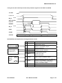
The safe interlock procedure describes how to control the ACO5000 drive with a PLC to have the
maximum safety concerning an unexpected start. It describes the logic concerning all the terminal block
signals according to the diagram presented in the last paragraph.
The START and STOP input can be activated by two types of signals. There are permanent signals or
impulse signals (duration min. 5 ms in order to avoid unexpected activation by parasitic signal) selected
by program (parameter).
Power up procedure
1. Switch on the external +24 V power supply to feed the drive control.
ENABLE, STOP and START inputs are tied to 0 V.
2. Switch on the main power (400 VAC).
3. Wait until the READY relay close the output DR_R.
If the drive is in failure mode, it can be removed by the RESET input to let the READY relay be
energized.
4. At this point, the drive is in safe interlock mode.
•
•
•
•
•
It is possible to switch on the external +24 V power supply and the main power at the same
time.
If the ENABLE input is tied to +24 V before switching on the drive, the safe interlock mode
will not be available.
If the START input is tied to +24 V before switching on the drive, the start command will not
be activated. In this case, it will be necessary to apply 0 V on the START input before
applying +24 V again to activate de start command.
When the external +24 V power supply is on, if the ENABLE input is activated before the
READY relay has closed the output contact DR_R, the drive will go to a failure mode (E4 :
Power Fail) and a RESET command will be needed after the closing of the DR_R contact.
If the ENABLE input is activated before the main is applied, the drive is going to failure mode
(E4 : Power Fail) and a RESET command will be needed after the closing of the DR_R
contact.
Procedure to make a START from the safe interlock mode
1. Energized the safety relay by applying +24 V to the ENABLE input.
2. Wait until the safety relay feed-back contact EN_A is closed (open in the case of option –C)
3. Apply +24 V to the STOP input to enable the START input.
4. Wait for min. 10 ms before applying +24 V to the START input.
In the permanent signals option, maintain +24 V to the START input to keep the START mode.
In the impulse signals option, a 5 ms pulse is enough to maintain the START mode.
5. At this point, the drive is in START mode and the motor will begin to move.
•
•
If the START command is activated before the ENABLE input, the drive will go to a failure mode
(E0 : ENABLE) and a RESET command will be needed.
If +24 V is applied to the START input before or less then 10 ms after the STOP input, the
START command will not be activated. It will be necessary to apply 0 V on the START input and
do the correct procedure.
Procedure to return to the safe interlock mode
1. Make a STOP and wait until the rotor comes to a standstill.
(zero frequency signal can be used to know when the motor ends its deceleration)
In the permanent signals option, apply 0 V to the START input
In the impulse signals option, apply 0 V to the STOP input for more than 5 ms
2. Apply 0 V to the ENABLE input to release the safety relay.
3. Verify that the feed-back contact EN_A is open (standard version shown on the graphs below)
4. At this point the drive is in the safe interlock mode.
If the safety relay is released by applying 0 V to the ENABLE input before the STOP operation were
completed, the motor will run in free-wheel.
Page 16 / 24
User Manual ACO5000
S610-GB-0825