1
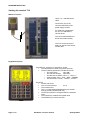
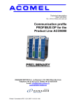
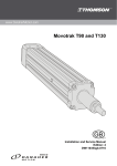
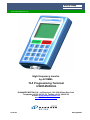
www.DanaherMotion.com
High frequency inverter
by ACOMEL
TL5 Programming Terminal
USER MANUAL
DANAHER MOTION S.A. La Pierreire 2, CH-1029 Villars-Ste-Croix
Telephone +41 21 631 33 33, Telefax +41 21 636 05 09
E-mail: [email protected]
www.DanaherMotion.com
20-06-08
S630-gb-0825
DANAHER MOTION S.A.
Page 2 / 20
ACO5000 / TL5 user manual
S630-gb-0825
DANAHER MOTION S.A.
Table of content
Starting the terminal TL5 ........................................................................................................................... 4
Where to connect ....................................................................................................................................... 4
Keypad description .................................................................................................................................... 4
Function key 2ndF...................................................................................................................................... 4
Function key 2ndF...................................................................................................................................... 5
Menu A: the drive information .................................................................................................................. 5
Menu B......................................................................................................................................................... 6
Menu B: Operating parameters................................................................................................................. 6
Menu B: Partition parameters ................................................................................................................... 8
The Nema input......................................................................................................................................... 11
Menu C: the terminals allocation ............................................................................................................ 11
Menu C: the available functions for the digital inputs.......................................................................... 11
Menu C: the available functions for the digital outputs ....................................................................... 12
Functions to allocate................................................................................................................................ 12
Menu C: the available function for the analogue outputs .................................................................... 13
Menu D: the dynamic parameters........................................................................................................... 13
Menu E: reversing the rotation ............................................................................................................... 14
Menu F: setting a new set point.............................................................................................................. 14
Menu G: displaying the actual values .................................................................................................... 15
Menu H: The failure history ..................................................................................................................... 15
Menu I: RESET .......................................................................................................................................... 15
Menu J: save the actual speed set point as default.............................................................................. 15
Menu K: setting the display..................................................................................................................... 15
Menu “Arrow Down”: miscellaneous instructions ............................................................................... 17
Menu “Arrow Up”: drive dialogue........................................................................................................... 18
Warnings ................................................................................................................................................... 18
Mechanical dimension and cutting......................................................................................................... 19
This manual is valid from:
1. Firmware version 1.50 or above of the ACO5000
2. Firmware version 1.07 of the TL5
S630-gb-0825
ACO5000 / TL5 user manual
Page 3 / 20
DANAHER MOTION S.A.
Starting the terminal TL5
Where to connect
Use a 1 to 1 standard serial
cable.
Connect the TL5 to the
connector KEYPAD of the
power supply module.
For multi-axis configuration,
the TL5 can address the
various drives.
The connexions between the
drives are made internally.
The TL5 can be connected
before or after to have turned
ON the drive.
Keypad description
The DISPLAY, 8 lines of 21 characters’, shows:
• The selected drive values using the 6 first lines
• The drive status (permanent) use the last 2 lines
o The active drive
“DR1 ON ”
o The unactive drive(s) “DR2 OFF”
o The direction of rotation “ROT <<”, “ROT >>”
o Various status “FCC”, “FCP”, “DEC”, “FREQ “
o The drive status “STOP”, “START”, “FAULT”
The KEYS:
• START and STOP
• The 10 numerical keys
0 to 9
• The numerical dot
• The 11 corresponding alphabetical keys activated
through pressing first the 2ndF key.
• The arrows up down to navigate within the selected
menu.
• The CLEAR key to delete the inputed value
• The ENTER key to cofirm the input
Page 4 / 20
ACO5000 / TL5 user manual
S630-gb-0825
DANAHER MOTION S.A.
Function key 2ndF
Pressing this key followed by one of the other will give you access to the menu corresponding to the letter
of the second key. For example pressing 2ndF followed by A (key 1) give you access to the menu A. That
is where you have to start.
Menu A: the drive information
Display
Description
Select your language by entering the corresponding
number and pressing ENTER
This is a read only information. It tells you if you can
access to the partition data.
0 = free access
1 = access locked by password. It is not possible to
change this setting using the TL5. To do it you need to
connect a PC, use the programming Window’s
software and to know the password set by your
machine supplier
Release number of the installed software.
In case of programming problems, please indicate this
number when calling our customer support.
The TL5 need the version 1.50 or later
x.xx
Shipping date of the unit. This is the date the unit left
our manufacturing plant in Switzerland.
yyyymmdd
Specific to each unit. Format yy (year) followed by ww
(week) and nnnn (incremental number during the
week. Note: until year 2010, the year will have only
one digit.
yywwnnnn
Display the maximum output current of the inverter.
This parameter is related to the drive rating and is
used to protect the drive in overload conditions as well
short circuit between phases and phase to ground.
S630-gb-0825
Values
ACO5005D :
ACO5008D :
ACO5012D :
ACO5020D :
7.5 A
12 A
18 A
30 A
Cumulated time in START mode
0.00 [H]
Cumulated time input voltage ON
0.00 [H]
ACO5000 / TL5 user manual
Page 5 / 20
DANAHER MOTION S.A.
Menu B
Display
Description
The menu B is divided into two sections:
• The operating parameters i.e. how the drive is communicating
with the machine and how it is operated.
• The partition parameters, i.e. the specific data of the motor. The
partition section can be repeated 32 times.
Menu B: Operating parameters
Display
Description
Selection of the control mode of the drive.
• LOCAL means you can operate the drive either through the
terminal bloc, the remote keypad or the connected PC.
• PROFIBUS allocated the full control to the field bus. No control or
data change via the TL5 is possible.
To set the PROFIBUS address of the drive.
This value depends from your Profibus configuration.
For further information see our specific Profibus user manual.
Configuration of the Profibus data.
This value depends from your Profibus configuration.
For further information see our specific Profibus user manual.
Function can be assigned to:
• SERIAL means to USB port or TL5 dedicated keypad
• imp means impulse signal to START and STOP terminals
• perm means permanent contact to START terminal.
By SERIAL or perm. selection, a permanent 24 VDC signal must be
applied to the STOP terminal.
Here you pre-set the displayed units for the speed i.e. Hz or RPM.
The number of poles of the motor will be taken into consideration
automatically.
If you want to lock any reversing of the rotating direction of the motor you
can do it here by entering no.
If you allow the reversing, the function can be assigned to:
• SERIAL means to USB port or TL5 dedicated keypad
• T.Bl. means to Control terminals in the drive front. One digital
input must be allocated to the function.
Input here a filter value for the analog speed reference input.
This factor is needed to smooth speed variations due to signal noise.
Value 0 to 10
Page 6 / 20
ACO5000 / TL5 user manual
S630-gb-0825
DANAHER MOTION S.A.
Display
Description
For all non-destructive failures where the STOP can be monitored, like:
Converter temperature, External Interlocks, …. We can choose between 2
ways of stopping the motor:
•
•
Coast to rest
Braking down using the deceleration’s ramp
For all non-destructive failure where the turn off can be delayed, like
Converter temperature, External Interlocks, Motor temperature, … a delay
time of 0 to 5 s can be input here.
This function is to allow the CNC to monitor the machine motion before
the converter trips.
At this step you decide the way you want to select the active partition
Function can be assigned to:
• SERIAL means to USB port or TL5 dedicated keypad
• T.Bl. means to Control terminals in the drive front.
The required number of programmable digital inputs must be allocated to
this selection.
NOTE:The partition No 0 is not available by T.Bl.
Internal timer which can be set from 0 to 5 s. This is a delay between the
frequency (speed) reached information and the enable of the MCM
function in order to let time to the rotor speed to stabilize.
Enter here the nominal value in V, of the voltage of your power supply.
Input value between 10 and 500 V.
All input mains voltages between 170 VAC and 530 VAC are considered
being inside of the drive tolerances.
A value allocated to one of the A_OUT1 or A_OUT2 can be internally
compared to a define voltage level (0 to 10 VDC) set in the next step.
Once this level is reached or exceeded an alarm can be triggered after a
set delay time.
Definition of the comparison level. Set a value between 0 and 10 VDC
Time delay to trigger the alarm once the comparison level above has been
reached or exceeded. This function must be allocated to one of the digital
outputs OUT1 to OUT4.
S630-gb-0825
ACO5000 / TL5 user manual
Page 7 / 20
DANAHER MOTION S.A.
Display
Description
To set the operating frequency of the intermediate DC-bus chopper. For
standard application, always use "HIGH". If the ambient temperature is
high, or if you experience repeated drive failure with the message
"Converter temperature too high", set this frequency to "LOW".
Menu B: Partition parameters
Display
Description
Here you need to ley in the password which will give you access to the
partition parameters
The password is: 616 followed by ENTER
Enter here the number of the partition you want to program.
Each partion contains all parameters related to the motor.
32 partitions are available in LOCAL mode, but only 31 in terminal block
mode.
This is the number of poles and not the number of pairs. It must be an
even number. This value is shown on the motor plate and/or in the motor
data sheet. Maximum number of poles: 2 - 1024
Input here the power of the motor which will correspond to a
10 V signal when PW is allocated to the analog output A_OUT1 or
A_OUT2
Value in A. This input is use to check the setting of current related
parameters as follow:
• IREF
≤ 150% of INOM (motor reference current)
• IFCC ≤ 100% of INOM (DC current braking)
• IFCP ≤ 20% of INOM (DC continuous current braking)
• IACC ≤ 200% of INOM (Acceleration current max.)
Set here the maximum acceleration current.
Value over 200% of INOM will be rejected.
The function If Im > IREF: is inhibited during acceleration and
deceleration.
Set here the maximum allowed current during operation. The limit value
is 150% of INOM . This value is used dor the comparison Im > IREF
Page 8 / 20
ACO5000 / TL5 user manual
S630-gb-0825
DANAHER MOTION S.A.
Display
Description
Frequency control source. At this step you can set if you want to assign
the output frequency of the drive, respectively the motor speed to the:
• SERIAL means to USB port or TL5 dedicated keypad
• T.Bl. i.e to the 0 to 10 V analog speed reference input A_IN in
the drive front or one of the 3 possible preset frequencies.
In case of selection of a SERIAL selection of the Freq. ctrl source, the
value entered or shown here will be taken as speed reference input
when the inverter is being turned ON. In running mode you can record
the actual value as default just by hitting the 2ndF J keys. Here again,
the input must be in Hz, input in RPM is not allowed and will lead to a
mis-setting.
Enter here the minimum frequency under which one you don't want to
operate your motor.
If you have selected the Freq. ctrl source from the T.Bl. you have the
possibility to define up to 3 pre-set speeds. The selection of one of
those pre-set speeds will be done applying +24V to the allocated
terminal(s). If this feature has been activated and no selection made
through terminals, the analog reference input will be active. Here again,
the input must be in Hz, input in RPM is not allowed and will lead to a
wrong setting.
The minimum acceleration time is set in seconds, between 0.1 to 512.
This is the acceleration time needed to reach the full speed of the motor.
If the set speed is the half of the full speed, the time to reach this speed
will be the half of the acceleration set time. This value is a minimum and
can’t be reduced within the dynamic parameters.
The minimum deceleration time is set in seconds, between 0.1 to 512.
This is the deceleration time needed to reach zero speed from the full
speed of the motor. If the set speed is the half of the full speed, the time
to stop will be the half of the deceleration set time. This value is a
minimum and can’t be reduced within the dynamic parameters.
This is only a speed measurement and not a speed closed loop.
Our sensor input accepts:
• Standard 5 V TTL encoder signals, 2 channels 90° phase
shifted, with or without index.
• Magneto-resistive sensor signal
Enter here the number of pulses per revolution: Value: 0 to 65535
To stabilize the display of the speed you can here input a filter value.
S630-gb-0825
ACO5000 / TL5 user manual
Page 9 / 20
DANAHER MOTION S.A.
Display
Description
Setting 0 rpm, the signal “reached speed” will be delivered at the end of
the acceleration when the speed is over 95% of the set value.
Setting an othe number of rpm will maintain the signal reached speed
active so long the output speed remain in this window (positive or
negative).
Using the speed feedback is it possible to monitor the slip of the motor
and issue a signal when the slip exceed a pre-set value.
Input of the maximum slip in RPM
Set the reaction of the drive when the motor current IM > IREF
• trip
you will trip the drive
• dec
you will reduce the output frequency FS to keep the
motor current lower than the reference current
• ignore the information. In this case the maximum current of the
inverter will be available for the motor.
The information that the current Im > IREF can be allocated to one of the
digital outputs OUT1 to OUT4
This is the delay to activate Im > IREF after the reach speed signal. This
delay is used to wait that the speed has stabilized before Im > IREF is
activated.
The resistance R of the motor winding is source of a voltage drop
proportional to the motor current I. The RI voltage will be added to the
output voltage US to obtain the nominal torque over the entire frequency
range. This function is mainly used when operating at the lower part of
the range. The value can be set between 0 and 30 V.
The number of RPM entered here correspond to the slip compensation
at motor nominal current INOM
The temperature monitoring of your motor can be made, using a PTC or
a KTY84-130. Please select here the temperature sensor integrated into
your motor windings.
If you have selected the KTY84-130, enter here the temperature value
you want to monitor and trip or stop the drive.
Page 10 / 20
ACO5000 / TL5 user manual
S630-gb-0825
DANAHER MOTION S.A.
The Nema input
Display
Description
Here you have 3 choices:
0
if you want to cancel a Nema
1
if you want to modify an existing one
2
if you want to create a new one
You can define up to 4 points for the Nema. The origine one 0V/0Hz is
automatically created.
Enter here the frequency of the first point, followed by ENTER
Enter here the voltage of the first point, followed by ENTER
Once you have completed your Nema, you need to close and confirm it
just by entering 2ndF B
Menu C: the terminals allocation
Display
Description
First step decide which type of allocation you want to do:
0
1
2
You want to allocate digital input(s)
- 8 inputs available
You want to allocate digital outputs(s) - 4 outputs available
You want to allocate analogue output(s) - 2 outputs vailable
Having selected 0, you can allocate the first available function of the
digital inputs.
If you key in “0”, the function is not allocated.
Menu C: the available functions for the digital inputs
Functions to allocate
VerExt
ISR
VerConsAn
FreFix0
FreFix1
SelPart0
SelPart1
SelPart2
SelPart3
SelPart4
NivMcm0
NivMcm1
SelMcm0
SelMcm1
SampleHoldMcm
S630-gb-0825
Comments on the allocated function
External interlock
Reverse rotating direction
Inhibit the speed reference analogue input
Fix frequency value 20
Fix frequency value 21
Partition selection value 20
Partition selection value 21
Partition selection value 22
Partition selection value 24
Partition selection value 25
MCM level value 20
MCM level value 21
MCM selection value 20
MCM selection value 21
Active the Sample & Hold reading
ACO5000 / TL5 user manual
Page 11 / 20
DANAHER MOTION S.A.
Display
Description
Having selected 1, you can allocate the first available function of the
digital outputs.
If you key in “0”, the function is not allocated.
Menu C: the available functions for the digital outputs
Functions to allocate
Reached frequency
Reached speed
Zero frequency
Zero speed
Start/stop
Motor overload
MCM output
Slip Output
Alarm output
Comp. output
Signal SDIG
Ext. interlocks
Converter overload
Def. aux. supply
Motor temp (PTC)
Converter temp (NTC)
Mains anomaly
Page 12 / 20
Comments on the allocated function
The allocated output will turn ON as soon the output frequency of the
converter is higher than 95% of the set value and after the MCM delay if
a value has been programmed. The MCM delay ca be monitored from
the CNC or PLC too.
The allocated output will turn ON as soon the measured motor speed
95% of the set value and MCM tempo as above.
This function need a speed feedback from motor
The allocated output will turn ON as soon the output frequency of the
converter is under 0.5 Hz
This function is only active in STOP mode
The allocated output will turn ON as soon the measured output speed is
lower than 2 pulses / sec..
This function is active only in STOP status
The allocated output will turn ON as soon the converter is in START
mode
The allocated output will turn ON as soon the motor current is higher
than the reference current: Im > IREF. This choice is only possible if the
condition “Ignore” or "trip" has been programmed.
The allocated output will turn ON as soon the MCM condition is true.
The allocated output will turn ON as soon as the SLIP is higher than the
programmed value. Need a speed feedback.
The allocated output will turn ON as soon as an alarm has been
triggered. This function is used in combination with the delayed trip by
non destructive failure
The allocated output will turn ON, after the programmed delay, when the
analog input exceed the programmed level.
Clock output corresponding to 6 time the output frequency
The allocated output will turn ON as soon the external interlock circuitry
is open.
The allocated output will turn ON if the output current exceeds the
maximum current of the converter. This current value is shown in the
info drive menu.
In failure free status, the allocated output is powered ON
The allocated output will turn ON if the motor temperature is to high
The allocated output will turn ON if the heatsink temperature exceeds
70°C, tolerance ± 3°C..
The mains voltage is compared to the value entered in the operating
parameters allocated output will turn ON if the mains voltage is out of the
tolerance of 480 V+10 % respectively 200 V –15%.
ACO5000 / TL5 user manual
S630-gb-0825
DANAHER MOTION S.A.
Display
Description
Having selected 2, you can allocate the first available function of the
analogue outputs.
If you key in “0”, the function is not allocated.
Two analogue outputs are available: 1 and 2
Menu C: the available function for the analogue outputs
• Fs for the output frequency:
• Im for the motor current :
• N speed of the motor
need a speed feedback from the motor
• Pw active output power
• Iw active output current
• Us for output voltage:
10 V = Fmax
10 V = 1.5 * INOM
10 V = NMAX
10 V = PMAX of motor
10 V = PMAX / 1.28 US
10 V = last US /FS Pt.
Menu D: the dynamic parameters
Display
Description
The acceleration time is set in seconds, between 0.1 to 512.
This is the acceleration time needed to reach the full speed of the motor.
If the set speed is the half of the full speed, the time to reach this speed
will be the half of the acceleration set time.
This time must be ≥ as the minimum acceleration time set within the
motor partition.
The deceleration time is set in seconds, between 0.1 to 512.
This is the deceleration time needed to reach zero speed from the full
speed of the motor. If the set speed is the half of the full speed, the time
to stop will be the half of the deceleration set time.
This time must be ≥ as the minimum deceleration time set within the
motor partition.
Value of the DC injected braking current. IFCC should not be higher than
the nominal current of the motor.
This function, when activated, is automatically initiated after a STOP
command, when the intermediate DC- bus reaches is ≤ 35 VDC.
DC braking current duration
Value of the permanent injected DC braking current. This function is
used when the motor needs to be braked (holding torque) at standstill,
for example to keep air bearing spindle from rotating at stop. We
suggest setting this current not higher than 20% of the motor nominal
current.
S630-gb-0825
ACO5000 / TL5 user manual
Page 13 / 20
DANAHER MOTION S.A.
Display
Description
Low frequency smoothing factor, to be used only in case of unstability at
low frequencies.
Set here the absolute reference value to which the motor current must
be compared to trigger the allocated output. This value is in A.
For one partition, 4 values can be entered.
The value to set here is the sensitivity of the SH monitoring. The value
set is the current increase (A) versus the recorded one, which will trigger
the corresponding output.
At the releasing of the allocated digital input, the instant value of Im is
recorded. As soon the motor current exceed “the recorded Im + ISH”, the
allocated output will be triggered.
For one partition, 4 values can be entered.
Enter here the dynamic sensitivity factor, value between 0 to 20 000.
Higher is the factor, lower is the sensitivity. The allocated output will turn
ON for approximately 200 ms.
For one partition, 4 values can be entered.
Menu E: reversing the rotation
With the sequence 2ndF E you can reverse the direction of rotation of the motor. This instruction is only
possible when the reversing of the rotation has been allowed within the operating parameters of the menu
B, and the reversing allocated to the SERIAL operation.
Menu F: setting a new set point
Display
Description
Set a new speed. The input can be in Hz or rpm depending of the choice
of the speed display within the operating parameters of the menu B.
Page 14 / 20
ACO5000 / TL5 user manual
S630-gb-0825
DANAHER MOTION S.A.
Menu G: displaying the actual values
Display
Description
Here the display when all values are shown.
Here the "zoomed" display when selected.
Menu H: The failure history
Display
Description
With the sequence 2ndF H you can display the failure history. The first
failure shown is the last happening. The last 8 failures are recorded.
The failure is displayed with a time information related to the time “power
applied” – see Menu A
Menu I: RESET
With the sequence 2ndF I you can RESET the drive after a failure.
Menu J: save the actual speed set point as default
With the sequence 2ndF I you can save the actual set point as default value within the menu B.
Menu K: setting the display
Display
Description
With the sequence 2ndF K you can select the values shown on the
display.
0
to move to the next choice
1
displays all values as shown with 2ndF G above
"Zoom" display enhances the character size of the "actual values" display
(See menu G). This display is only valid when only one ACO5xxx is
connected and is also automatically set back to the standard display when
more than one ACO5xxx are online.
0
to move to the next choice
1
to activate
Selection 1 – Speed display is set in Hz
Fc = frequency set point, Im = motor current, Fs = output frequency
Iw = active current, P&Voltages = power and voltages
0
1
S630-gb-0825
to move to the next choice
to activate
ACO5000 / TL5 user manual
Page 15 / 20
DANAHER MOTION S.A.
Selection 2 – Speed display is set in rpm
Nc = speed set point, Im = motor current, Ns = output speed
Iw = active current, P&Voltages = power and voltages
0
1
to move to the next choice
to activate
Selection 3 – Speed display in rpm and speed feedback
Nc = speed set point, Im = motor current, Nr = measured speed
Iw = active current, P&Voltages = power and voltages
0
1
to move to the next choice
to activate
Selection 4
As selection 1, but temperatures instead of power and voltage.
0
1
to move to the next choice
to activate
Selection 5
As selection 2, but temperatures instead of power and voltage.
0
1
to move to the next choice
to activate
Selection 6
As selection 3, but temperatures instead of power and voltage.
0
1
to move to the next choice
to activate
Selection 7
As selection 1, but analogue outputs instead of power and voltage.
0
1
to move to the next choice
to activate
Selection 8
As selection 2, but analogue outputs instead of power and voltage.
0
1
to move to the next choice
to activate
Selection 9
As selection 3, but analogue outputs instead of power and voltage.
0
1
to move to the next choice
to activate
Selection 10
This choice displays all temperatures and anlogue outputs status
0
1
Page 16 / 20
to move to the next choice
to activate
ACO5000 / TL5 user manual
S630-gb-0825
DANAHER MOTION S.A.
Selection 11
Show alternatively for 5 s all blocks above, from choice 1 to choice 10
to move to the next choice
to activate
0
1
When you are operating a multi-axis sytem and select 1=yes you will enter
a list of choice as above and display at the same time 2 parameters for
each drive. Here to you have the option of displaying alternate values for 5
s. Same parameters for all drives will be displayed at the same time.
Menu “Arrow Down”: miscellaneous instructions
Display
Description
With the sequence 2ndF “Arrow Down” you can:
•
set up the contrast of the display
Read the version number of the embedded firmware of the TL5
Read the modification number of the embedded hardware of the TL5
Transfer all the programmed data from the connected ACO5000 drive
into the TL5 memory in order to transfert them to an other drive.
Download all the stored data drom a TL5 to the connected ACO5000
drive, an easy way to program identical drives.
When you want to download the save data from the TL5, you have the
choice to save all partitions
0
1
S630-gb-0825
to move to the next choice
to activate
ACO5000 / TL5 user manual
Page 17 / 20
DANAHER MOTION S.A.
Select here the partition number you want to copy…
And select here in which partition of the drive you want to download it.
Menu “Arrow Up”: drive dialogue
Display
Description
With the sequence 2ndF “Arrow Up” you can open the drive dialogue
menu to select an other drive when operating a multi-drive configuration.
•
Just key in the drive you want to connect to.
Instruction to rescan the configuration for drives.
0
1
no action
rescan the configuration
Warnings
Display
Description
This message is displayed in case of communication problem between
the TL5 and the ACO5000.
It is displayed too when you connect the TL5 to a drive already
connected to a PC via the USB port. As the message required it, just
remove all the connections and reconnect the TL5 only.
For other messages please consult the user manual of the windows
software, ref. S620_GB
The ACO5 firmware is not supported (older than version 1.50). Please
use the windows software to proceed to the requested upgrade.
Please contact us to get the last version of the firmware.
Page 18 / 20
ACO5000 / TL5 user manual
S630-gb-0825
DANAHER MOTION S.A.
Mechanical dimension and cutting
Overall dimensions H = 140 mm / W = 87 mm / T = 31 mm, weight 240 gr
********************************
Part number: HTL5
**********************************
Cutting out in a cabinet door for TL5 integration, metal sheet thickness max. 2.5 mm
Dimensions in mm
S630-gb-0825
ACO5000 / TL5 user manual
Page 19 / 20
DANAHER MOTION S.A.
MANUAL TL5_GB / printed in Switzerland © 06/2008
Modification reserved
Page 20 / 20
ACO5000 / TL5 user manual
Danaher Motion SA
La Pierreire 2
CH-1029 Villars-Ste-Croix
Switzerland
Tel +41 (0) 21 631 33 33
Fax +41 (0) 21 636 05 09
E-mail [email protected]
Internet www.DanaherMotion.com
S630-gb-0825