1
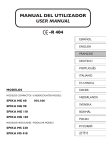
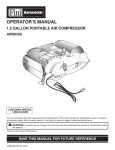
MANUAL DEL UTILIZADOR USER MANUAL ESPAÑOL ENGLISH FRANÇAIS DEUTSCH PORTUGUÊS ITALIANO MODELOS HNICA DANSK MODELOS COMPACTOS / UNDERCOUNTER MODELS SPIKA NG 60 VV E NEDERLANDS 104.166 SPIKA NG 90 SPIKA NG 110 SPIKA NG 140 SVENSKA BOKMÅL POLSKI MODELOS MODULARES / MODULAR MODELS SPIKA MS 220 SPIKA MS 410 РУССКИЙ MANUAL DEL UTILIZADOR USER MANUAL ENGLISH INTRODUCTION Thank you for purchasing a ‘Spika Series’ Ice Cube Maker by ITV. You have purchased one of the most reliable ice-making products on the market today. Carefully read the instructions contained in this manual since they provide important information relative to safety during installation, use, and maintenance. WARNING The installation of this equipment should be done by the Service Department. The socket should always be placed on an accessible location. Always disconnect the power supply from the machine before any cleaning or maintenance service. Any change needed on the electrical installation for the appropriate connection of the machine, should be exclusively performed by qualified and certified professional personnel only. Any use by the ice maker not intended to produce ice, using potable water, is considered inappropriate. It is extremely dangerous to modify or intend to modify this machine, and will void warranty. This machine should not be used by children or handicapped without the proper supervision and monitoring. This machine is not intended to be used outdoors nor exposed to the rain. It is mandatory to ground the equipment to avoid possible electric shock on individuals or damages to the equipment. The machine should be grounded pursuant local and/or national regulations as the case may be. The manufacturer shall be held harmless in case of damages arising due to the lack of the ground installation. In order to assure the proper operation and efficiency of this equipment, it is of paramount importance to follow the recommendations of the manufacturer, especially those related to cleaning and maintenance operations, which should be performed by qualified personnel only. CAUTION: The intervention of non-qualified personnel, besides of being dangerous, could result in serious malfunctioning. In case of damages, contact your distributor. We recommend always using original spare parts. ITV reserves the right to make changes in specifications and design without prior notice. RECEPTION OF THE MACHINE Inspect the outside packing. In case of damages, MAKE THE CORRESPONDING CLAIM TO THE CARRIER. To confirm the existence of damages, UNPACK THE MACHINE IN THE PRESENCE OF THE CARRIER and state any damage on the equipment on the reception document or freight document. 24 (1) Packing: On the outside, it contains a label with the manufacturing number. (2) Exterior of the equipment: On the back of the equipment, there appears a label with the same characteristics as the previos one. (3) Nameplate: On the back of the machine. Check that in interior of the machine the installation kit is complete and comprises: 7GSSTHVEMRLSWIJSYVPIKWERHQERYEP ;EVVERX]ERHWIVMEPRYQFIV ;EXIVGSRRIGXMSR CAUTION: All packing elements (plastic bags, carton boxes and wood pallets) should be kept outside the reach of children, as they are a source of potential hazard. INSTALLATION 1. LOCATION OF ICE MACHINE This ice maker is not designed for outdoor operation.The icemaker should not be located next to ovens, grills or other high heat producing equipment. The SPIKA machines are designed to operate at room temperature between 5ºC (41ºF) and 43ºC (109.4ºF). There may be some difficulties in ice slab removal under the minimum temperatures. Above the maximum temperature, the life of the compressor is shortened and the production is substantially lower. 25 ENGLISH Always state the machine number and model. This number is printed on three locations: ENGLISH The air cooled SPIKA NG (undercounter) ice makers take the air through the front section, and drive it off through the lateral, back and also front louvers due to their new oblique condenser structure and placement. Do not place anything on the top of ice maker or facing the front grille. In case the front grille is either total or partially obstructed, or due to its placement it receives hot air from another device, we recommend, in case it is not possible to change the location, to install a water cooled machine. The air cooled SPIKA MS (modular) ice makers take the air through the back section and drive it off through the two lateral louvers. In the case it is not possible to respect the minimum distances recommended (see the picture in point 3) for these machines we recommend to install a water cooled unit. The location must allow enough clearance for water, drain and electrical connections in the rear of the ice machine. It is important that the water inlet piping do not pass near sources of heat so as not to lose ice production. 2. LEVELING THE ICE MACHINE Use a level on top of ice machine in order to ensure the equipment is perfectly leveled. Only for SPIKA NG (undercounter) machines: Screw the leveling legs onto the bottom of the ice machine as far as possible. Move the machine into its final position. Use a level on top of the ice machine. Turn each foot as necessary to level the ice machine from front to back and side to side. 26 The minimum clearance values you can see below are recommended for efficient operation and servicing. UNDERCOUNTER MODELS MODULAR MODELS 10cm (4’’) 15cm (6’’) 15cm (6’’) 15cm (6’’) FRONT 15cm (6’’) FRONT 10cm (4’’) 75cm (29,5’’) 4. CONNECTION DIAGRAM The location must allow enough clearance for water drain and electrical connections in the rear of the ice machine. UNDERCOUNTER MODELS MODULAR MODELS 15cm (6’’) 10cm (4’’) Plug Plug Socket Tap Socket Water Inlet Tap Drain Water Inlet Bin Drain Bin Drain 27 ENGLISH 3. MINIMUM DISTANCE TO OBSTACLES ENGLISH 5. WATER SUPPLY The quality of the water supplied to the ice machine will have an impact on the time between cleanings and ultimately on the life of the product (mainly in water cooled units). It also will have a remarkable influence on the appearance, hardness and flavor of the ice. Local water conditions may require treatment of the water to inhibit scale formation, improve taste and clarity. If you are installing a water filter system, refer to the installation instructions supplied with the filter system. Pressure should be between 10 and 85 psi (0.7 and 6 bar). If pressure overpasses such values, install a pressure regulator. ATTENTION: The machine shall be plumbed. 6. DRAINAGE Drainage should be located below the level of the machine, at 5,9’’ (150 mm) minimum. It is convenient that the drainage pipe is 30 mm (1.18’’) inside diameter and with a minimum gradient of 3 cm/ meter (0.36’’/ft), see figure. CORRECT Descending INCORRECT Ascending INCORRECT 28 It is mandatory to ground the equipment: to avoid possible discharges on individuals or damages to the equipment, the machine should be grounded pursuant local and/or national regulations as the case may be. The manufacturer shall be held harmless in case of damages arising due to the lack of the ground installation. In case the supply cable is damaged, it should be replaced by a cable of special assembly to be furnished by the manufacturer or after-sales service. Such replacement should be performed by qualified technical service only. The machine should be places in such a way as to allow a minimum space between the back and the wall to allow an easy access and without risks to the cable plug. Safeguard the socket. It is convenient to install adequate switches and fuses. Voltage is indicated in the nameplate and on the technical specifications of this manual. Variation on voltage above the 10% stated on the nameplate could result on damages or prevent the machine start-up. VOLTAGE FREQUENCY PHASE TOTAL AMPS FUSE (A) (A) SPIK A NG 60 220V / 50Hz / 1Ph 3 16 SPIK A NG 90 220V / 50Hz / 1Ph 3,5 16 SPIK A NG 110 220V / 50Hz / 1Ph 5 16 SPIK A NG 140 220V / 50Hz / 1Ph 5,5 16 SPIK A NG 220 220V / 50Hz / 1Ph 7 16 SPIK A MS 410 380-440V / 50Hz / 3Ph 4,2 16 SPIK A MS 410 208-230V / 60Hz / 3Ph 5,8 16 MODELS 8. INSTALLATION OF MODULAR EQUIPMENTS ON TOP OF BINS Modular ice makers should be installed on top of bins, following the instructions contained in this manual. The resistance and stability of the container-machine/s assembly should be verified, as well as the fastening elements. Follow bin manufacturer instructions. 29 ENGLISH 7. ELECTRICAL CONNECTION ENGLISH START-UP (1) Previous Checkup a) Is the machine leveled? b) Voltage and frequency are the same as those on the nameplate? c) Are the discharges connected and operating? d) Will the ambient temperature and water temperature remain in the following range? ROOM WATER MAXIMUN 43º C / 109º F 35ºC / 95º F MINIMUM 5º C / 41º F 5ºC / 41º F e) Is water pressure appropriate? MINIMO 0.7 Bar (10 psig) MAXIMO 6 Bar (85 psig) NOTE: In case input water pressure is higher than 85 psi (6 bar), install a pressure regulator. For undercounter machines: In case the room temperature exceeds 29.5ºC (85ºF ) or water inlet temperature exceeds 20ºC (68ºF ) the following adjustments should be made to ensure a proper efficiency. The wheel G1 should have 2 more pins than G2, one by each side of those from the other. Air temp >29.5ºC (85ºF) Water temp > 20ºC (68ºF) G1 G2 G3 Air temp <29.5ºC (85ºF) Water temp <20ºC (68ºF) G1 G2 G3 G1 G2 G3 SPIK A NG 125 6 4 2 12 10 5 SPIK A NG 175 9 7 3 12 10 5 SPIK A NG 215 9 7 3 12 10 5 SPIK A NG 285 9 7 3 12 10 5 Indicating the number of white pins The frist pin in G2 and G3 wheels must coincide in their position. 30 Once the installation instructions are followed (ventilation, site conditions, temperatures, water quality, etc.), proceed as follows: 1) Open the water inlet.Verify the no existence of leakages. 2) For undercounter models open the door and remove the protection elements on the shield. For modular models remove the two locking screws on top of machine, take off the front panel and remove protection elements on the shield and also on the thickness sensor. 3) Verify that the shield moves freely. For modular models verify also the thickness sensor moves freely. 4) Connect the machine to the power supply. 5) For undercounter models: push the blue switch on the machine front side. For modular models: push the blue switch found on the back of the machine and then set the ice-wash switch to the position I. 6) Verify that there are no vibrations or frictions on the elements. 7) Verify that the water fall to the evaporator is occurring uniformly and all ice cubes are properly watered. 8) Close door (for undercounter models) / Replace the front panel in its place (for modular models). :IVMJ]XLEXEJXIVXLI½REPG]GPIXLIJVSWXSRXLIEWTMVEXMSRTMTIMWEXQQMRSJXLIGSQTVIWWSV 10) For modular models:Verify the ice slab with the pictures below. In case the thickness sensor needs to be regulated, rotate the thickness adjustment screw CW to increase bridge thickness. Rotate CCW to decrease bridge thickness. For undercounter models adjust the cycle thermostat. Thickness Sensor Too Big Just Right Too Small Damages due to the lack of maintenance and cleaning operations are not included on the warranty. 31 ENGLISH (2) Start-Up ENGLISH (3) Sequence of Operation FOR UNDERCOUNTER MODELS: Initial Start-up: It’s recommended that the first time the machine is started (or the water tray has been emptied) it begins with the harvest sequence to ensure the water tray is filled. Freeze sequence: The compressor is energized. The micro G2 de-energizes the hot gas valve, so the evaporator begins to freeze. The micro G2 energizes the water pump so the water circulates from the water tray to the upper distributor, flowing through each cube cell, where it freezes. Harvest sequence: The compressor will continue energized. The micro G2 energizes the hot gas valve during a certain time. The micro G3 at the same time energizes the water inlet valve during a certain time to fill the water tray with the appropriate quantity of water. The ice slab slides off the evaporator and into the bin. After this, the freeze sequence starts again. When storage bin is full the stock thermostat detects a low temperature and the machine shuts off at the end of the freeze sequence. The ice machine remains off until enough ice has been removed from the storage bin and the stock thermostat doesn’t detect this low temperature. FOR MODULAR MODELS: Initial Start-up: The pump and the drain electrovalve are energized during 30 seconds to empty the water tray preventing the scale build-up in water. Then the pump and the drain electrovalve are de-energized, and the water inlet valve is energized filling the water tray until the water level sensor detects the water reaches the appropriate level. Then the freeze sequence starts. Freeze sequence: The compressor is energized and the water pump is energized after 30 seconds. The water inlet valve is also energized at the same time that the water pump to replenish water level and then de-energized. The compressor and water pump will continue energized until the thickness sensor detects the thickness of the ice slab is the appropriate. Then the harvest sequence starts. Harvest sequence: The compressor will continue energized.The hot gas valve is energized throughout the harvest phase to divert hot refrigerant gas into the evaporator. The water pump and the drain electrovalve are energized during 45 seconds to empty the water tray and remove mineral deposits. After this (water pump and drain electrovalve de-energized) the water inlet valve is energized filling the water tray until the water level sensor detects water reaches the level. The ice slab slides off the evaporator and into the bin. The momentary opening and re-closing of the shield indicates the harvest sequence has finished and goes to the freeze sequence. When the storage bin is full, the ice shield is held open during more than 30 seconds and the machine shuts off. The ice machine remains off until enough ice has been removed from the storage bin to allow the ice shield swings back to the operating position 32 It is the User’s responsibility to keep the ice machine and ice storage bin in a sanitary condition. Ice machines also require occasional cleaning of their water systems with a specifically designed chemical. This chemical dissolves mineral build up that forms during the ice making process. Sanitize the ice storage bin as frequently as local health codes require, and every time the ice machine is cleaned and sanitized. The ice machine’s water system should be cleaned and sanitized at least twice a year. CAUTION: Do not mix Ice Machine Cleaner and Sanitizer solutions together. WARNING: Wear rubber gloves and safety goggles when handling Ice Machine Cleaner or Sanitizer. WARNING: Unit should always be disconnected during maintenance/cleaning procedures. CLEANING WATER DISTRIBUTION SYSTEM (1) Cleaning Water Distribution System for Undercounter Models 1) Set the switch to the OFF position after ice falls from the evaporator at the end of a harvest cycle, or set the switch to the OFF position and allow the ice to melt off the evaporator. CAUTION: Never use anything to force ice from the evaporator. 2) Remove the back metal lid and the top panel (if it need be to make easier the cleaning operations). Top panel Back metal lid 33 ENGLISH MAINTENANCE AND CLEANING PROCEDURES ENGLISH 3) Remove all ice from the bin. 4) Remove the auxiliary pipe for drain operations near the pump and empty the water tray. Return it to their original position to avoid water spill. Pipe for drain 5) Prepare a solution of an appropriate product for the cleaning of ice machines (lime). Do not use hydrochloric acid. We recommend the use of any NSF approved scale removal product prepared according to the manufacturer’s instructions. 6) Fill water tray with the solution. Water tray 7[MXGLGSQTVIWWSVW[MXGLWII½KYVIFIPS[XSTSWMXMSRERHW[MXGLSRQEGLMRIMRSVHIVXSVYR[EXIV pump. Let solution stand for 30-40 minutes and then switch off the machine. Compressor switch 34 Shield 12) Clean all surfaces of the shield with the cleaner solution using a brush (not a wire brush) or cloth. Rinse all areas with water. 13) Clean all the interior surfaces of the freezing compartment (including storage bin) with the cleaner solution using a brush or cloth. Rinse all areas with water. 14) Mix a solution of sanitizer using approved (EPA/FDA) sodium hypochlorite food equipment sanitizer to form a solution with 100 - 200 ppm free chlorine yield. 15) Sanitize all surfaces of the shield applying liberally the sanitizer solution using a cloth or sponge. 16) Sanitize all the interior surfaces of the freezing compartment (including the storage bin) applying liberally sanitizer solution, using a cloth or sponge. 17) Return shield to its position. 18) Connect power and water supplies. 19) Fill water reservoir with the sanitizer solution. 20) Switch on machine in order to run water pump. Let solution stand for 20 minutes and switch off. 21) Remove the auxiliary pipe to drain and purge out the sanitizer solution and residue. Replace it. Fill the water reservoir with water and switch on the machine to allow water to circulate for 5 minutes and then stop the machine. Repeat this operation two more times to rinse thoroughly. 6IQSZIXLIEY\MPMEV]LSWIXSHVEMRXLI[EXIV6ITPEGIMXERH½PPXLIXVE][MXL[EXIVXSIRWYVIXLITYQT works properly. 23) Switch on compressor switch (position I). 24) Return the back metal lid and the top panel to their position. 7[MXGLSRQEGLMRIERHHMWGEVHXLI½VWXX[SLEVZIWXW (2) Cleaning Water Distribution System for Modular Models 1) Set Ice-wash switch to the OFF position (position 0) after ice falls from the evaporator at the end of a harvest cycle, or set the ice-wash switch to the OFF position and allow the ice to melt off the evaporator. CAUTION: Never use anything to force ice from the evaporator. Damage may result. 35 ENGLISH 8) Disconnect power and water supplies. 9) Remove the auxiliary pipe to drain and purge out the ice machine scale remover and residue. Replace it. 10) Mix enough cleaning solution (as in point 5) to clean parts and interior food zone surfaces. 11) Remove shield. ENGLISH 2) Remove the front panel. Front panel 3) Prepare a solution of an appropriate product for the cleaning of ice machines (lime). Do not use hydrochloric acid. We recommend the use of any NSF approved scale removal product. In modular QEGLMRIWXLI[EXIVFYGOIXMW½PPIHEYXSQEXMGEPP]WS[IVIGSQQIRHXSTVITEVIETVIZMSYWWSPYXMSRJSV example 0.15 l) according to the manufacturer’s instructions with the total quantity of product needed for the water tray (0.3 l for MS 440 and 6 l for MS 880). 4) To start a cleaning cycle, move the ice-wash switch to the WASH position (position II). The machine will HVEMRXLIVIWIVZSMVERHVI½PPMX4SYVXLIWGEPIVIQSZIVWSPYXMSRMRXSXLIVIWIVZSMV Shield Thickness sensor Water level sensor Water tray Ice-wash switch 5) Allow the solution to circulate in the water system for 30-40 minutes and then set the ice-wash switch to the OFF position. 6) To purge out the ice machine scale remover and residue move the ice-wash switch to the WASH (the QEGLMRI[MPPHVEMRXLIVIWIVZSMVERHVI½PPMXERHXLIRWIXXLIMGI[EWLW[MXGLXSXLI3**TSWMXMSR 7) Disconnect power and water supplies. 8) Mix a cleaning solution. 9) Remove shield and water tray. 36 Adjustment screw Water level sensor Thickness sensor Water tray Shield 11) Clean the interior surfaces of the freezing compartment (including walls, plastic parts of the evaporator, distributor...) and the front panel with the cleaner solution using a brush or cloth. 12) Mix a solution of sanitizer using approved (EPA/FDA) sodium hypochlorite food equipment sanitizer to form a solution with 100 t 200 ppm free chlorine yield. 13) Sanitize all surfaces of the ice thickness sensor, water level sensor, shield and water tray applying liberally the sanitizer solution using a cloth or sponge. 14) Sanitize the interior surfaces of the freezing compartment (including walls, plastic parts of the evaporator, distributor...) and the front panel applying liberally the sanitizer solution using a cloth or sponge. 15) Return the water tray and shield to their normal positions. 16) Connect power and water supplies. 17) To start a sanitation cleaning cycle, move the ice-wash switch to the WASH position. The machine will HVEMRXLIVIWIVZSMVERHVI½PPMX4SYVXLIWERMXM^IVMRXSXLI[EXIVVIWIVZSMVXSKIXEWSPYXMSREWMRXLI point 12 (the volume in the water tray is approximately 6 l for MS 880 and 3 l for MS 440). 18) Allow the solution to circulate in the water system for 20 minutes and then set the ice-wash switch to the OFF position. 19) To purge out the sanitizer solution and residue move the ice-wash switch to the WASH position (drain ERHVI½PPERHEPPS[XLI[EXIVXSGMVGYPEXIJSVQMRYXIWERHXLIRQSZIXLIW[MXGLXSXLI3**TSWMXMSR (drain). Repeat this operation two more times to rinse thoroughly. 20) Return the panel to their position. 7IXXLIMGI[EWLW[MXGLXSXLI32TSWMXMSRTSWMXMSR-ERHHMWGEVHXLI½VWXX[SLEVZIWXW CLEANING THE ICE BIN (FOR UNDERCOUNTER MODELS) 1) Disconnect the machine, close water faucet and empty storage bin of ice 2) Use the cleaner/water solution to clean all surfaces of the bin. Use a nylon brush or cloth. Then rinse all areas thoroughly with clean water. 3) Use the sanitizer/water solution to sanitize all surfaces of the bin. Use a nylon brush or cloth. 4) Rinse with plenty of water, dry, run the machine and open water faucet. 37 ENGLISH 10) Clean the metal surfaces of the thickness sensor, water level sensor, the adjustment screw, the shield and the water tray with the cleaner solution using a brush (not a wire brush) or cloth. ENGLISH CLEANING THE CONDENSER (1) Air Condenser 1) Disconnect machine and close water faucet. *SVYRHIVGSYRXIVQSHIPWVIQSZIXLIJVSRXKVMHF]TVIWWMRKXLIX[SGPMTWTPEGIHEXVMKLXWMHIWII½KYVI Front grid *SVQSHYPEVQSHIPWVIQSZIXLIFEGOTERIPWII½KYVI Back panel 3) Clean condenser using a vacuum cleaner, soft brush or low pressure air. Clean from top to bottom, not side to side. &IGEVIJYPRSXXSFIRHXLIGSRHIRWIV½RW (2) Water Condenser The water condenser may require cleaning due to scale build-up. The cleaning procedures require special pumps and cleaning solutions. They must be performed by qualified maintenance or service personnel. 38 Clean the area around the ice machine as often as necessary to maintain cleanliness. Sponge any dust and dirt off the outside of the ice machine with mild soap and water. Wipe dry with a clean soft cloth. A commercial grade stainless steel cleaner/polish can be used as necessary. CHECKING FOR WATER LEAKS This must be done whenever maintenance is carried out on the machine: check all water connexions, braces, tubes and hoses in order to eliminate leaks and prevent breakages and flooding. USER TROUBLESHOOTING GUIDE UNDERCOUNTER MODELS: PROBLEM PROBABLE CAUSE SOLUTION None of the electrical parts work. The machine is unplugged. Plug in the machine and verify shocket power. Bin thermostat open. Ice touching bin tube. Remove ice from the bin. Bin thermostat open. No ice touching bin tube. Adjust thermostat (electric box under top cover). All the electrical parts work but not compressor. (water doesn´t get frozen). Compresor switch is in the “WASH” position (0). Switch to “ICE” position (1). No water in tray. Not incoming water. Check water supply. Inlet strain at water valve blocked. Check an clean. Bin full and ice touching thermostat tube, but machine doesn´t stop. Bin thermostat doen´t open (only operates at harvest time). Adjust thermostat (electric box under top cover). Ice slab empty or too thick . Desadjusted cycle time. Adjust thermostat (electric box under top cover). Difficult to release ice slab at harvest. Unit bad leveled (tilted to back). Level; down front. Not enough harvest time. Add more pins to cam timer wheels (as label indications). Not uniform flow pattern at evaporator. Dirty or scaled distributor. Perform descaling procedure. Remove and clean distributor (pull from two clips at distributor sides). Unit run and stops alternatively itself Safety presostat opens. Clean air condenser (behind front grid). For fur ther problems call aftersales ser vice. 39 ENGLISH CLEANING THE OUTSIDE OF THE MACHINE ENGLISH MODULAR MODELS: PROBLEM PROBABLE CAUSE SOLUTION None of the electrical parts work. The machine is unplugged. Plug in the machine and verify shocket power. Rear switch OFF. Switch ON. Front switch position “0”. Move to “ICE” (behind front panel). All the electrical parts work but not compressor. (water doesn´t get frozen). Front switch position “WASH”. Move to “ICE” (behind front panel). No water in tray. Not incoming water. Check water supply. Inlet strain at water valve blocked. Check an clean. Water level probe too low. Move up (steel rod beside pump). Defective drain valve (check drain leak during ice stage). Disamble and clean. Shield splash leaks. Check shield position. Water overflows tray. Level probe to high or scaled. Adjust / clean. Ice slab empty or too thick. Desadjusted/scaled thickness probe. Adjust / clean. Difficult to release ice slab at harvest. Unit bad leveled (tilted to back). Level; down front. Not uniform flow pattern at evaporator. Dirty or scaled distributor. Perform descaling procedure. Remove an clean distributor (pull from two clips at distributor sides). Low production. Dirty condenser. Clean (check also incoming water/air temperature). Unit stops after few time running. Safety presostat opens. Clean air condenser (back). Not enoug water to end cycle. For fur ther problems call aftersales ser vice. 40 ENGLISH ELECTRICAL DIAGRAMS SPIKA NG (UNDERCOUNTER MODELS) PRACTICAL G2 1 (L) 4 B M G 3 RED BROWN N G1 K 1 2 1 H G2 G3 N P L1 4 2 5 R L M 1 C S Q 5 TIMER COMPONENTS B F G G1 G2 G3 H J K P Q R S T1 T2 Ig Il ----- L M R P M S M H M 3 3 26/05/10 . ES-16-1 B C 2 IG F-J IG L1 4 K Q Il 2 4 r BLUE 2 2 4 Il G3 1 1 G2 2 4 r 1 G1 1 M Violet Brown (C) 4 3(C) White 3 (C) (H) 2 T2 White T1 T2 (L) 4 2 4 Orange (L)3 (H) 2 2 4 2 Violet 4 2 3(L) (C) 4 Orange M T1 1 G2 1 Brown G1 1 Brown G THEORATICAL Motor pump Fan pressostat (air) Cam timer motor Circuit safety timer Circuit timer Circuit timer (water inlet valve) Safety pressostat Condensing pressostat (water) Condensing electrovalve (water) Water inlet valve Hot gas electrovalve Fan motor Compressor Stock thermostat Cycle thermostat ON/OFF Switch Cleaning switch for water condenser 41 1 2 3 3 3 3 F-J (1) WIRING DIAGRAM, ONE PHASE. N Ip L I II I H TT BLUE BROWN RED VIOLET BLACK N WHITE BROWN F 500mA 0 ICE WASH PRES CORT DAUX NW ESP BLUE Com B EW EGC DRAIN JP1 JP2 JP3 JP4 JP5 JP6 ENGLISH SPIKA MS (MODULAR MODELS) BLACK GREY VIOLET 1 0 6 4 J RED S WHITE LE0 LE1 LE2 LE3 NW R B P ESP Q D COMPONENTS H N I S R J B P Q D NW ESP Ip Safety pressostat Shield switch Ice-wash switch (3 positions) Compressor Fan motor Condensing pressostat (only air). Pump motor Water inlet valve Hot gas valve Drain electrovalve Water level sensor Thickness sensor ON/OFF switch 42 A1 31 A2 32 Ip R S T N ENGLISH (2) WIRING DIAGRAM, THREE PHASES. 95 J 96 R I II 0 I TT BLUE BROWN RED VIOLET H N BLACK NW BROWN BLUE BLACK GREY VIOLET RED WHITE Com B EW EGC DRAIN ICE WASH PRES CORT DAUX NW ESP JP1 JP2 JP3 JP4 JP5 JP6 WHITE F 500mA Rc P LE0 LE1 LE2 LE3 Q D ESP COMPONENTS H N I S R J B P Q D NW ESP B Safety pressostat Shield switch Ice-wash switch (3 positions) Compressor Fan motor Condensing pressostat (only air) Pump motor Water inlet valve Hot gas valve Drain electrovalve Water level sensor Thickness sensor 43 S 97 98