1
®
Badger Meter Europa GmbH
LMS RF High-End
Oil Management System RF High-End
USER MANUAL
December 2009 (v. 2.15)
OMS software v2.21 MK v2.20 DK v2.40
LMS_RFH_BA_02_0912
Table of contents
I
c
1.
Basic safety recommendations ......................................................................................... 1
2.
Introduction ......................................................................................................................... 2
2.2. Overview .......................................................................................................................3
2.3. Composition and dataflow of the RF-System ................................................................4
2.4. Technical data ...............................................................................................................5
2.5. Wall fastening of the keypads .......................................................................................5
2.6. Keypad description........................................................................................................6
2.7. Operation modes...........................................................................................................7
1.1.1
1.1.2
1.1.3
1.1.4
3.
RF-System with PC operation .................................................................................................. 7
RF-system with host operation ................................................................................................. 7
Stand alone ................................................................................................................................. 7
Calibrateable / PTB mode ......................................................................................................... 7
Master keypad ..................................................................................................................... 7
3.1. Standard screen ............................................................................................................7
3.2. Settings / supervisor menues ........................................................................................8
3.3. Menu INI: set date and time ..........................................................................................8
3.4. Menu CNF (configuration) .............................................................................................8
3.4.1. Work order validation ................................................................................................................. 8
3.4.2. WO archive (Printout or storing of the work order/dispense results) .................................. 8
3.4.3. Archive on PC (Archive of the work orders/dispenses) ........................................................ 9
3.5. Menu DK (test communication) .....................................................................................9
3.6. Menu REP (reports) ......................................................................................................9
3.7. Menu overview ............................................................................................................10
4.
Dispense keypad ............................................................................................................... 11
4.1. Standard screen ..........................................................................................................11
4.2. Settings / Supervisor menu .........................................................................................11
4.3. Menu CNF (configuration) ...........................................................................................11
4.3.1. System Reset............................................................................................................................ 11
4.3.2. Mileage type .............................................................................................................................. 11
4.3.3. Top off timer .............................................................................................................................. 11
4.3.4. Internal printer........................................................................................................................... 11
4.3.5. External printer ......................................................................................................................... 11
4.3.6. Barcode scanner ...................................................................................................................... 12
4.3.7. Buzzer ........................................................................................................................................ 12
4.3.8. Emergency mode ..................................................................................................................... 12
4.3.9. Batch quantity locked .............................................................................................................. 13
4.3.10. Hose ID First ............................................................................................................................. 13
4.4. Menu MET (delete prepared WOs) .............................................................................13
4.5. Menu REP (reports) - External printer........................................................................13
4.6. Menu 190 (internal ticket printer) ................................................................................14
4.7. LNK (RF test between master and dispense keypad) .................................................14
4.8. DLY (delays the meter after a dispense).....................................................................14
4.9. Dispense / Start a work order......................................................................................15
4.9.1. Schematic overview ................................................................................................................. 15
4.9.2. Dispense process ..................................................................................................................... 15
Table of contents
II
4.10. Menu overview ............................................................................................................17
5.
LM OG-RF meter ................................................................................................................ 18
5.1. Key description............................................................................................................18
5.2. RF mode (standard preselection mode) ......................................................................18
5.2.1. Procedure .................................................................................................................................. 19
5.2.2. Illustration .................................................................................................................................. 19
5.3. AUTO mode ................................................................................................................20
5.3.1. Procedure .................................................................................................................................. 20
5.3.2. Reset to standard mode .......................................................................................................... 20
5.4. Electrical override........................................................................................................20
5.5. Changing the battery ...................................................................................................20
5.6. Programming the LM OG-RF meter ............................................................................20
6.
OMS High End software v2.21 .......................................................................................... 21
6.1. Software installation ....................................................................................................21
6.1.1. System requirements ............................................................................................................... 21
6.1.2. Installation ................................................................................................................................. 21
6.1.3. MSI Engine ................................................................................................................................ 22
6.1.4. Apache Web Server and PHP ................................................................................................ 22
6.1.5. MySQL Server .......................................................................................................................... 22
6.1.6. Badger High End Administration Site .................................................................................... 23
6.1.7. Keypad Server (KPS) .............................................................................................................. 23
6.1.8. Execute Batch file .................................................................................................................... 23
6.1.9. Create Desktop Launcher ....................................................................................................... 23
6.1.10. Uninstalling ................................................................................................................................ 23
6.2. System configuration...................................................................................................24
6.3. First start of the OMS software ...................................................................................24
6.4. Menu: Report by work order........................................................................................25
6.5. Menu: Setup ................................................................................................................26
6.5.1. System initialization ................................................................................................................. 26
6.5.2. Configuration............................................................................................................................. 27
6.5.3. Host configuration .................................................................................................................... 29
6.6. Menu: Entity ................................................................................................................29
6.6.1.
6.6.2.
6.6.3.
6.6.4.
6.6.5.
Fluid / Product configuration ................................................................................................... 29
Tank configuration.................................................................................................................... 29
Hose (Meter) configuration ..................................................................................................... 30
Dispense keypad configuration .............................................................................................. 30
User configuration .................................................................................................................... 31
6.7. Tree menu ...................................................................................................................31
6.7.1. Tree product .............................................................................................................................. 31
6.7.2. Network tree .............................................................................................................................. 32
6.8. Menu: Dispense ..........................................................................................................33
6.9. Menu: File ...................................................................................................................34
6.9.1.
6.9.2.
6.9.3.
6.9.4.
6.9.5.
6.9.6.
Setup file .................................................................................................................................... 34
Pending work orders file.......................................................................................................... 35
Closed work orders file ............................................................................................................ 35
Database file ............................................................................................................................. 36
Export file................................................................................................................................... 36
Purge pending WO .................................................................................................................. 37
6.10. Menu: Display .............................................................................................................37
6.10.1. Tank level .................................................................................................................................. 37
6.10.2. Fluid usage ................................................................................................................................ 38
Table of contents
III
6.10.3. Pending WO .............................................................................................................................. 38
6.11. Menu: Report ..............................................................................................................38
6.11.1. Report initialisation ................................................................................................................... 38
6.11.2. Configuration............................................................................................................................. 39
6.11.3. Work order................................................................................................................................. 39
7.
KPS software v0.5.2 .......................................................................................................... 40
7.1. The KPS tasks ............................................................................................................40
7.2. KPS - a first check.......................................................................................................40
7.2.1.
7.2.2.
7.2.3.
7.2.4.
7.2.5.
8.
Menu overview.......................................................................................................................... 41
Preferences ............................................................................................................................... 41
Test communication between KPS and master keypad ..................................................... 42
Init (transmit configuration settings) ...................................................................................... 43
User (Transmit only user data)............................................................................................... 43
Troubleshooting ................................................................................................................ 44
8.1. Dispense keypad error messages...............................................................................44
8.1.1. Problem: PC or HOST is not responding .............................................................................. 45
8.1.2. Problem: "Communication Error" ........................................................................................... 45
8.2. Other problems ...........................................................................................................46
9.
Worksheets ........................................................................................................................ 47
10. Appendix I: Host communication .................................................................................... 51
11. Manufacturer´s declaration .............................................................................................. 56
12. Warranty ............................................................................................................................. 57
13. DIN ISO certificate ............................................................................................................. 57
Basic safety recommendations
page 1/57
1. Basic safety recommendations
Before installing or using this product, please read this instruction manual thoroughly.
Only qualified personnel should install and/or repair this product. If a fault appears, contact
your distributor.
Installation
Do not place any unit on an unstable surface that may allow it to fall.
Never place the units above a radiator or heating unit.
Route all cabling away from potential hazards.
Isolate from the mains before removing any covers.
Power connection
Use only the type of power source suitable for electronic equipment. If in doubt, contact
your distributor. Ensure that any power cables are of a sufficiently high current rating.
All units must be earthed to eliminate risk of electric shock.
Failure to properly earth a unit may cause damage to that unit or data stored within it.
Setup & operation
Adjust only those controls that are covered by the operating instructions. Improper
adjustment of other controls may result in damage, incorrect operation or loss of data.
Cleaning
Switch off all units and isolate from mains before cleaning.
Clean using a damp cloth. Do not use liquid or aerosol cleaners.
Repair of faults
Disconnect all units from power supply and have it repaired by a qualified service person if
any of the following occurs:
• If any power cord or plug is damaged or frayed
• If a unit does not operate normally when operating instructions are followed
• If a unit exposed to rain/water or if any liquid has been spilled into it
• If a unit has been dropped or damaged
• If a unit shows a change in performance, indicating a need for service.
Failure to adhere to these safety instructions
may result in damage to the product or serious
bodily injury.
LMS_RFH_BA_02_0912
Introduction
page 2/57
2. Introduction
The Badger Meter High-End oil management system has been designed to control and
monitor the consumption and inventory balances of automotive fluid products with minimal
installation and programming costs. Badger Meter has used its years of expertise in the
automated meter reading market to develop a modular control system utilizing RF
communications.
The high end RF oil management system hardware consists of one master keypad and at
least one dispense keypad as well as at least one radio frequency electronic preset meter
(LM OG-RF). The master keypad handles serial communication between the PC or a host
server (ERP system) and RF communication to the dispense keypads in the system. The
system verifies the operator’s pin number and validates the work order number, fluid
quantities and the valid hose / meter.
The master keypad can communicate with up to 36 dispense keypads that can be
positioned to support the workflow of the facility the best way. Each dispense keypad can
control up to 24 meters. The system supports up to 16 tanks and 16 fluids as a part of the
system configuration. The system supports 250 unique operator IDs and pin numbers.
The system utilizes spread spectrum frequency hopping RF technology to prevent
communication problems with other equipment in the facility. The RF system will look for a
clear channel for transmission to insure that there is reliable communications at all times.
Communication distances are typically up to 100 m but can go up to 300 m with
unobstructed line of sight. A remote antenna is available for situations where multiple
buildings are involved in the installation.
The PC is used to configure the system, maintain system data and enter work orders. The
service desk would utilize the PC to enter a work order selecting the fluid and quantity
required. The PC can stack as many work orders as required, limited only by the local
memory of the PC. There is no need to predetermine where the work is going to occur. This
allows the flexibility to service a vehicle at any open bay and select a meter when the work
is going to be performed. When the work order is going to be performed the service
personnel simply enters their pin number, work order and hose that is going to be used at
the dispense keypad.
There are a number of system utilization reports by user; fluid type, tank or meters available
for the system’s management.
Optionally the system can be connected with an ERP system via its RS-232 interface. The
real-time communication is based on an open interface protocol (ASCII-code) and can be
easily adapted to local conditions.
A unique, patented feature of the system is that the RF meter’s dispense trigger is locked
until an authorization from the keypad is received. After the dispense batch is completed,
the user can top off if more fluid is required, the actual dispensed amount is sent back to
the keypad and the meter returns to the locked status. Additionally, the meter can be
installed on portable dolly systems offering control and monitoring of high-cost lubrication
products.
LMS_RFH_BA_02_0912
Introduction
page 3/57
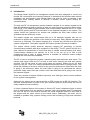
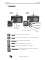
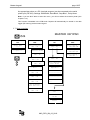
2.2. Overview
OMS software
Master
terminal
Users / Mechanics
Printer
Host (ERP)
Dispense terminal 1
without printer
Dispense terminal 2
with printer
**
Tank 1
Product 1
Tank 2
Tank 3
Product 2
Tank 4
Product 3
* The users have access to each meter / hose
** 24 meters per terminal but not more than 250 meters on the whole.
LMS_RFH_BA_02_0912
*
Introduction
page 4/57
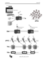
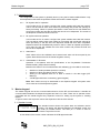
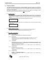
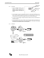
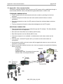
2.3. Composition and dataflow of the RF-System
Master Keypad
Dispense terminal
500
1200
Dispenses
Dispenses
printer
RS-232
OMS software
RS-232
Host
RS-232
printer
RS-232
Computer Keypad
RS-232 Interface
MySQL - Database
KPS - Keypad Server
Init
2
3
1
Apache Server - platform
Add
High End Launcher - OMS software
The main data streams:
1 The OMS software stores the configuration data into the MySQL database.
2 By using the menu Edit / Init of the KPS software the configuration data are being processed to the
master keypad and finally via radio to all dispense keypads.
3 The KPS records all dispenses in the MySQL database.
LMS_RFH_BA_02_0912
Introduction
page 5/57
2.4. Technical data
Power supply
230 VAC 50/60 Hz (Glas fuse 5x20mm 200mA T)
EMC-approval
EN300 220-1
RF communication
2-way 868MHz according to FCC
part 15.247 and part 15.109
16 bit encryption
Operating temperature
-10° C to +60° C
Internal printer
Thermal printer Type FT190 (optional)
External printer
Epson LX300 or similar (optional)
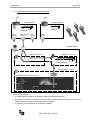
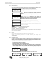
2.5. Wall fastening of the keypads
The keypad should be mounted upright with the antenna pointing upward, near a 230 VAC
electrical socket, to a structurally sound wall through the two holes on the top of the keypad
casing. Height on the wall should be at eye level. Care should be taken to avoid mounting
behind any steel objects (tool storage cabinets and metal chain linked fences) that may block
the RF communication signal. Care should also be taken to avoid direct, significant heat
sources.
97
187
[mm]
Mounting dimensions for keypad
Bore diameter: 5 mm
LMS_RFH_BA_02_0912
Introduction
page 6/57
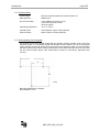
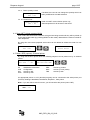
2.6. Keypad description
Dispense
Keypad
Master
Keypad
Interface to OMS
software (RS232)
optional
Internal printer
Type FT190
External printer
port (RS-232)
Power supply
230 VAC 50/60Hz
Datalogger
RF-Memory (*)
(*) necessary for PTB mode
Power supply
230 VAC 50/60Hz
External printer
(RS232)
if no RF-Memory
Host link
(RS232)
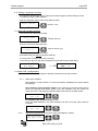
Scroll key: Used to select options on the active display
Home key: Pressing this key will return display to the PIN number and time/date
screens
Backspace key: Used to backspace when entering data
Enter Key: Used to enter data and move to the next screen
Space key: Used to enter a space character when entering data
Alphanumeric keys: Used to enter data on display. Hold down key until desired
character is on display. Then release the key.
LMS_RFH_BA_02_0912
Master keypad
page 7/57
2.7. Operation modes
The configuration of the system is generally done by using the PC-based OMS software. Only
some special functions like the operation modes are set at the master keypad.
2.7.1.
RF-System with PC operation
In this mode the PC is used to configure the system entities and install the network.
The PC will be used to enter work orders for processing and provide the queuing for
future processing. When an operator processes a work order the PC will validate the
work order number and provide the fluid and amount to be dispensed. The results of
the dispense will then be stored on the PC.
2.7.2.
RF-system with host operation
In this mode the PC is used to configure the system entities and install the network.
The host will be used to enter work orders for processing and provide the queuing for
future processing. It will also store the dispense results that have been completed.
Dispense results can be additionally stored on the PC. When an operator processes a
work order the host will validate the work order number and provide the fluid and
amount to be dispensed.
2.7.3.
Stand alone
Work orders will not be validated; each entered work order will be accepted by the
system. Data will be stored in the master keypad’s memory.
2.7.4.
Calibrateable / PTB mode
Operation in accordance with the specifications of the Physikalisch Technische
Bundes-anstalt (PTB) in Braunschweig.
Based on the German act of measurement and calibrating §13 from March 23rd 1992.
•
•
•
•
detection of small quantities (less than 0,5 litres)
detection of faulty impulses at the RF-meters
Storing of the dispense data for at least 3 months in the data logger (RFMemory).
A PTB-approved meter is necessary (green keypad)
Note: Each meter can only be associated to one dispense keypad. All system users
can access each of the dispense keypads.
3. Master keypad
The master keypad acts as the communications director for the RF communications. It handles all
communications between the dispense keypads and the PC or Host. There are no operator menus
associated with the master keypad only supervisor menus for setting up the system or creating
reports.
To gain access to the supervisor menus the supervisor PIN has to be entered.
3.1. Standard screen
01jan2009 12:48
*V2.20 A748
The standard screen shows the system date and software version
number. The display will alternate between the standard screen and
the enter pin number screen. The enter pin n° screen is used to
access the supervisor menus.
A star ahead of the version number indicates the PTB approved mode.
LMS_RFH_BA_02_0912
Master keypad
page 8/57
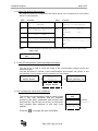
3.2. Settings / supervisor menues
The following changes can only be made at the master keypad. All other settings can be
changed by using the OMS software.
Enter the supervisor PIN to enter setup (default: 0000).
Enter PIN No.
____
Numeric xxxx
+
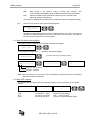
3.3. Menu INI: set date and time
Choose the menu INI and press enter.
Enter time
--:--
Format hh:mm
+
Enter the actual time and press enter.
Enter Date
--/jan/----
Format dd.mm.yyyy
+
Enter the date. Scroll from left to right through the fields by using the scroll key.
Enter behind the year without using the enter key.
You may see a message “Order List not Empty”
In this case you have to clear the transactions in the master keypad (CNF Menu).
Order List
Not Empty
Clear Transacts
YES / NO
+
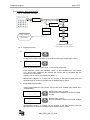
3.4. Menu CNF (configuration)
The menu is used to set the system’s operation modes and archiving methods.
3.4.1.
Work order validation
WO validation is used to define, if a work order shall be validated by the system before
processing it.
Host validation (host operation mode) in this mode the work order number will be
send to the aligned ERP (DMS) system. Only after validation from the system the
meter will unlock. Afterwards the dispense data will be send to the ERP system.
WO Valid. HOST
YES / NO
+
+
PC validation (PC operation mode) in this mode the work order number will be sent
to the PC (OMS Software). Only after validation from the PC will the order number is
accepted.
WO Valid. PC
YES / NO
3.4.2.
+
+
WO archive (Printout or storing of the work order/dispense results)
WO archived
None Mem Print
+
+
LMS_RFH_BA_02_0912
Master keypad
page 9/57
Mem
Data stored in an optional memory module (RF memory). The
communication isproceeded via the PTB authorized B-protocol (EN 45501).
Print
After each dispense, the data will be printed out on the external printer.
Each line displays one dispense.
This function is disabled in the PTB-mode by default and cannot be enabled manually.
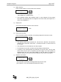
3.4.3.
Archive on PC (Archive of the work orders/dispenses)
Archive on PC ?
YES / NO
+
+
All dispense results will be stored on the PC (OMS Software). If the PC is currently not
available, the data will tagged as “not sent” in the memory of the master. The data will
be sent, as soon as the PC is connected again.
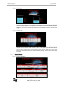
3.5. Menu DK (test communication)
The menu is used to check the communication between all keypads.
Test All DKs
YES / NO
+
+
In the following example each " - " stands for a Dispense keypad.
Start DKpd Test
Press Enter
+
Results 1-16
OOK------------
+
3 keypads are set up in following sample
Results 17-32
---------------
+
Results 33-36
----
Keypad 3 - No connection
Keypad 2 - Detected
Keypad 1 - Detected
Note: After the DK test you may have to reboot all dispense keypads, because the standard
user login has been deactivated.
3.6. Menu REP (reports)
By using this function reports about the following subjects can be printed out by an external
printer.
Select Report >
INI
CNF
WO
USR
Select Report >
Initialising
PRO
Configuration HOS
sort list by work order
sort list by user SLA
Select Report >
+
sort list by product
sort list by hose (meter)
TNK
sort list by tank
sort list by dispense keypad (slave)
LMS_RFH_BA_02_0912
+
Master keypad
page 10/57
An appropriate printer or a PC (terminal program) can be connected to the serial
printer port (RS 232). Settings: 9600 Baud, Data Bits 8, Stop Bits 1, Parity None.
Note: If you are NOT able to enter this menu, you did not select the external printer (see
chapter 2.4.2).
This function is disabled in the PTB-mode. Reports will automatically be stored in the data
logger (RF-memory) at the master keypad.
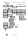
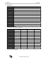
3.7. Menu overview
MASTER KEYPAD
INI
CNF
DK
REP
Enter Time
--:--
Clear Transacts
YES / NO
Test All DKs
YES / NO
Select Report > INI CNF COM
Enter Date
--/jan/----
Print WO
Enter To Print
Select Report > USR PRO HOS
Confirm Clear
YES / NO
System Reset
YES / NO
Confirm Reset
YES / NO
Select Report > SLA dat ...
Test All DKs
YES / NO
Start DKpd Test
Press Enter
Keypad Timeout
16---
Start Comm
DKpd No X
Buzzer
YES / NO
Results 1-16
---------------
WO Valid. HOST
YES / NO
Results 17-32
---------------
WO Valid. PC
YES / NO
Results 33-36
----
WO archived
None Mem Print
Archive on PC
YES / NO
Dispense kpd
Tst
Start Comm
No XX
MK DK Interface
Error
LMS_RFH_BA_02_0912
Dispense keypad
page 11/57
4. Dispense keypad
The dispense keypads are responsible for the communication with the RF-meters. The user starts a
work order from the keypad. After the dispense operation has been completed the keypad will
receive the actual amount dispensed from the meter. The dispense keypad then sends the dispense
results to the master keypad.
The system can handle up to 36 dispense keypads. Up to 24 meters can be assigned to each
keypad but each meter can only be assigned to one dispense keypad.
4.1. Standard screen
The standard screen shows the system date and firmware version number. The display will
alternate between the standard screen and the enter PIN number screen. The “Enter PIN No”
screen is used to access the system and to start a dispense or to access the supervisor
menus.
A star ahead of the version number indicates the PTB approved mode.
*V2.30
F088
Enter a user PIN to start a work order or the supervisor PIN to enter the supervisor menus
(Default 0000).
Enter PIN No.
____
4.2. Settings / Supervisor menu
The following configuration options are only available at the dispense keypad.
The default value for the Supervisor PIN is 0000 (four times zero).
4.3. Menu CNF (configuration)
4.3.1.
System Reset
Resets the system parameters to original factory settings.
4.3.2.
Mileage type
Defines the unit for the “Free Alphanumeric” field (see chapter 4.9.2, Pos.3).
Should be permanently defined in the OMS Software (see chapter 6.5.2
„Configuration“).
4.3.3.
Top off timer
Specifies the amount of time, how long user can make additional dispenses. Is the
time allowed after a dispense is completed before the meter will automatically lockout
and send the dispense results back.
Should be permanently defined in the OMS Software (see chapter 6.5.2
„Configuration“)
4.3.4.
Internal printer
Enables the internal ticket printer.
Should be permanently defined in the OMS Software (see chapter 6.5.2
„Configuration“)
4.3.5.
External printer
Enables the external report printer port.
Should be permanently defined in the OMS Software (see chapter 6.5.2
„Configuration“)
LMS_RFH_BA_02_0912
Dispense keypad
4.3.6.
page 12/57
Barcode scanner
This menu will define the external printer port as a barcode reader port (RS232), if the
“External Printer” is enabled the “Barcode Scanner” menu will disappear.
Barcode Scanner
YES / NO
Selecting YES will enable the Barcode Scanner
Data can be entered with keypad & barcode
OFF
Scanner Locked
OFF PIN All
scanner
PIN
All
PIN has to entered by barcode scanner
All data have to entered with barcode scanner
When PIN or All is selected you can choose an
additional prefix character. The prefix character will not be
displayed and cannot be entered on the keypad.
Pin Encoded
YES / NO
Encode Prefix#
Display Timeout
90-
Choose the desired prefix, available characters are:
# $ % &´ ( ) * +, - Space / : ; < = > ? @ [ ] ^
` { | } ! ” #
Defines the time, how long the scanned information will be
shown on the display.
Remark:
We can recommend the following barcode scanners.
Wall mounted:
Datalogic Magellan 1000i
Handheld: Datalogic Firescan D131
Scanner has to be programmed according to our specification; Null modem adapter
has to be used in between.
4.3.7.
Buzzer
You can switch off the beep sound, each time you press a button.
Should be permanently defined in the OMS Software (see chapter 6.5.2
„Configuration“)
4.3.8.
Emergency mode
In case the connection between master and dispense keypad is interrupted for some
reason you have the possibility to set a dispense keypad into the emergency mode.
The keypad is working then independently. The emergency mode will indicated with a
capital E on the main screen beside the version number.
• All WO will be accepted, no validation.
• Data will be stored in the local dispense keypad.
• The dispense keypad will try with each new dispense to setup a communication
with the master keypad. Once the master replies again the dispense keypad will
automatically sent all the missing data and finishes the emergency mode (the “E”
will disappear).
Emergency mode
YES / NO
+
+
If the communication failed you will see the character E on the main screen.
Communication
Failed
Emerceny mode
ON
4sec
LMS_RFH_BA_02_0912
E *V2.20
Main screen
3DB7
Dispense keypad
4.3.9.
page 13/57
Batch quantity locked
Batch Qty Locked
YES / NO
If enabled, the user can not change the quantity which has
been predefined in the OMS software.
4.3.10. Hose ID First
Used for HOST communication option only.
Selected product ID will be sent to the HOST.
Hose ID First
YES / NO
4.4. Menu MET (delete prepared WOs)
Work orders that have been entered at a keypad are being stored until they will be picked up
by the appropriate meter (by pressing RESET at the meter). Meanwhile the meter is locked for
other dispenses.
By using this menu these prepared work orders can be deleted to release the meter for new
WOs.
Init All Hoses
YES / NO
+
Reset All Hoses
Press Enter
+
4.5. Menu REP (reports) - External printer
By using this function reports about the following subjects can be printed out by an external
printer.
Select Report->
INI CNF ... WO
INI
CNF
WO
USR
Select Report->
USR PRO HOS TNK
Initialization Information
Configuration
sort list by WO
sort list by user
PRO
HOS
TNK
+
+
sort list by product
sort list by hose (meter)
sort list by tank
An appropriate printer or a PC (terminal program) can be connected to the serial printer port
(RS-232). Settings: 9600 Baud, Data Bits 8, Stop Bits 1, Parity None.
Note: If you are able to enter this menu, you did not select the printer (menu CNF).
Internal Printer
YES / NO
LMS_RFH_BA_02_0912
Dispense keypad
page 14/57
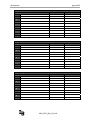
4.6. Menu 190 (internal ticket printer)
By using this menu the configuration and status reports can be printed out by the internal
printer FT-190 (optional)
Menu
Example
Menu
Example
FLU
FLUID Adress: 258 Size: 18
1-> 1 / SAE10W40
PEN
Meter 1
inactive
(asking or unreachable)
HOS
HOSE Address: 142 Size:12
1-> 0.036.700.715 / 1
PAR
TNK
TANK Address: 194 Size: 8
1->
10000 / LITER
Unit
Miles)
AN-Field
etc.
USR
USER Adress: 402 Size: 20
1->
1234 / HR.MUELLER
WO
WO 1 485801020230022B
Note:
MEM
Km (or
Yes
Item Size Max Nb Address
Between
---- ---- --- -- ------ ------etc.
For this feature to be used you must have selected internal printer option in the
(Menu CNF)
Internal Printer
YES / NO
4.7. LNK (RF test between master and dispense keypad)
The LNK menu is used to check the quality of RF communication between master and
dispense keypad.
The test will perform a number of test communications and measure the quantity of lost
transmissions. The link quality 10 is the maximum you can achieve.
Start Link Test
Press Enter
Test in
Progress
Test Complete
Link Quality:10
Enter to Cancel
Press Enter
4.8. DLY (delays the meter after a dispense)
This function is only necessary, when a meter is used
with a very high frequency and the dispense
procedure has been accelerated with barcode data
entry and the “Top off timer” set to zero. It will prevent
from possible data collisions in this case (very
seldom).
Press the
to change the value (0=Default)
LMS_RFH_BA_02_0912
DLY
Dispense Delay
0
Hose Busy
Please wait 45s
Available:
45-90-135 s
Dispense keypad
page 15/57
4.9. Dispense / Start a work order
4.9.1.
Schematic overview
Enter PIN No.
----
Enter WO No.
123A2---------
Enter Hose
02-
Hose ID First
YES / NO
Quantity
3.0-
WO Valid. HOST
YES / NO
WO Valid. PC
YES / NO
Enter for
Dispense
External validation
By OMS Software (PC) Or Host (DMS)
4.9.2.
1.)
Order stored in Dispense Keypad, Until the RESET is pressed on meter. Dispense process
Enter PIN No.
____
+
To start a work order a mechanic / user enters his PIN (see chapter 6.6.5 “User“).
2.)
Enter WO No.
_______________
+
Enter an alphanumeric number (max. 16 chars) and press Enter.
In the operation modes “WO Validation HOST” or “WO Validation PC” (see chapter
3.4.1 “Work order validation”) the entered WO number will be compared with the
numbers set in the system.
(Setting of work orders: see chapter 6.8 „Menu: “)
Alphanumeric keypad: To change from the numeric to the letter keypad, press the
equivalent key for at least 3 seconds until the desired letter is shown.
3.) Enter additional free fields:
These optional fields are only shown, if they have been enabled (see chapter 6.5.2
„Configuration“).
Free Alphanu.
__________
Free Numeric
__________
+
+
Alphanumeric field, 10 chars:
Can be used for example for the licences plate
number.
Numeric field, 8 chars:
Can for example be used for the actual mileage
Alphanumeric keypad: To change from the numeric to the letter keypad, press the
equivalent key for at least 3 seconds until the desired letter is shown.
LMS_RFH_BA_02_0912
Dispense keypad
page 16/57
4.) Meter selection
Enter a preset meter ID, for the product that is desired.
Enter Hose
---
+
• Only meters that are assigned to the current keypad can be selected.
(See chapter 6.7.2 „Network tree“)
• In the operation modes “WO validation HOST” or “WO validation PC” the system
will check if the desired product is assigned to this work order (see chapter 3.4.1
„Work order validation “).
5.) Display fluid
The chosen fluid type is shown for three seconds.
Fluid
Product Name
3 secs.
6.) Enter product quantity
Enter the desired quantity. Optionally, the quantity assigned to this WO is shown.
Quantity
----
+
• The quantity can be chosen between 0,0 - 99,9 and 100 - 999 liters. The maximum
quantity in the PTB-mode is 90,0 liters. A quantity less than 0, 5 liters will be not
be accepted.
• The preselection can be made with one decimal place.
• For quantities of more than 100 liters will meter display will decrement.
• A quantity of 0.0 will deactivate the preselection on the RF meter. The RF meter
will not latch and the user is required to hold the trigger in the open position to
dispense fluid. The user must press RESET on the RF meter to complete the
dispense operation and communicate the dispense order result to the keypad.
7.) Dispense confirmation
Enter For
Dispense
+
The work order is now ready for being picked up by the RF meter
[see chapter 5.2 ”RF mode (standard preselection mode)”].
LMS_RFH_BA_02_0912
Dispense keypad
page 17/57
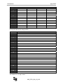
4.10. Menu overview
DISPENSE KEYPAD
Enter PIN No.
----
Enter WO No.
---------------
Enter Hose
---
Quantity
----
Enter For
Dispense
Fluid
Product Name
Supervisor 0000
CNF
MET
REP
190
LNK
System Reset
YES / NO
Init All Hoses
YES / NO
Select Report >
Select
FLU HOS TNK USE
Start Link Test
Press Enter
Select Report >
WO
Mileage Type
KM / Miles
Topoff Timer
0---Internal
Printer
External
Printer
Select
PEN PAR MEM
Select
SWO ... ... ...
Test in
Progress
Test Complete
Link Quality:
Reset All Hoses
Press Enter
Hose RESET
Hose No ---
DLY
Dispense Delay
0
Barcode Scanner
YES / NO
Sanner Locked
OFF PIN All
Buzzer
YES / NO
Emergenc mode
YES / NO
Hose Busy
Please wait 45s
Pin Encoded
YES / NO
Encode Prefix #
Batch Qty
Locked
Hose ID First
YES / NO
Barcode menu
disappears if the
external printer is
on YES.
Available characters:
# $ % &´ ( ) * + , Space / : ; < = > ? @ [
] ^
` { | } ! ” #
Display Timeout
90-
LMS_RFH_BA_02_0912
Available:
45-90-135 s
LM OG-RF meter
page 18/57
5. LM OG-RF meter
The meter is equipped with RF communications for communicating dispense authorization and result
information. Once a work order has been set up, the operator simply pulls the trigger and the
authorized amount of fluid for that meter will dispense. The valve will automatically shut off when the
full quantity has been dispensed. A “Top Off” feature allows additional quantities to be dispensed and
tracked after the valve closes. Upon completion of the dispense effort, the valve locks prohibiting any
unauthorized dispense to occur.
For more detailed instructions, see the LM OG P manual delivered with the meter.
5.1. Key description
The following keys (except for RESET and SHUT-OFF) are only active in the AUTO mode
(or Manual mode). The meter will autonomous as a standard preselection meter. How to enter
this mode see chapter 5.3.1
Used to enter the dispense quantity to be used (10 liter steps).
In operational mode it shows the five latest dispensed amounts.
Used to enter the dispense quantity to be used (1 liter steps).
Used to enter the dispense quantity to be used (0.1 liter steps).
In operational mode it shows the actual dispense flow rate.
Used to display the accumulated fluid total and the resettable total when held for
3 seconds.
Used to enter and exit the auto mode when RF communications are not available.
Used to accept a dispense order from the keypad. Used in normal operating
mode (RF, manual or auto) to clear the previously programmed batch and to
reset the meter. Press the button while viewing the resettable total to set it back
to zero.
The SHUT-OFF is used to stop the flow manually through an electrical override.
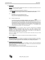
5.2. RF mode (standard preselection mode)
Work order validation via the dispense keypad.
When the battery pack is attached to the meter,
the meter will automatically enter the RF mode.
The trigger is in a locked-out position and no oil
can be dispensed until a dispense order has
been received by the meter.
LMS_RFH_BA_02_0912
L
LM OG-RF meter
5.2.1.
page 19/57
Dispensed
quantity
Procedure
1. Press the RESET button on the
meter to enable it to receive a
dispense order provided by the
dispense keypad. The trigger will
unlock.
L
Batch size
RF Com.
2. Pull the trigger to begin the dispensing of fluid. The valve will automatically lock in
place, even though the trigger will fall back to the closed position. The flow will
automatically shut off when the programmed amount has been dispensed.
3. To top off, pull the trigger to dispense fluid and release when the desired amount
has been reached.
4. Press the RESET button when finished. The total quantity will be transmitted to the
keypad and the meter will return to a locked-out position. The meter is now ready
to receive the next dispense order from the keypad.
5.2.2.
Illustration
02
02
CLACK
10 sec
Press the
RESET button
Order stored in Dispense Keypad The red button will STOP
a dispense at any time.
02
10 sec
Result stored in
Dispense Keypad
Preselection: Pull the trigger until it
latches and RELEASE the trigger.
No preselection (0 liter): Pull and HOLD
the trigger. The trigger won´t latch.
Press the
RESET button
LMS_RFH_BA_02_0912
LM OG-RF meter
page 20/57
5.3. AUTO mode
Attention: This function allows unauthorized dispenses. The dispense information will not be
associated to any mechanic / operator.
• Operation will take place as described in chapter 5.1.
• The total dispensed quantity will be stored under the general work order number (999999)
• The AUTO . sign at the display’s lower left corner indicates the manual mode
5.3.1.
Procedure
Procedure only for authorized personnel!
Ask your service department for the procedure.
5.3.2.
Reset to standard mode
To set back the meter into standard preselection mode, press the
button and
start a communication with the assigned dispense (see chapter 4.2.1)
If the communication was successful (no “F02”) the meter will lockout and fall back in
the preselection mode. The total quantity, which has been dispensed during the AUTO
mode will be automatically transmitted to the master keypad. It will be assigned to the
“Misc.WO-Number” (Default 999999), the user is named as “???”. The dispense result
will be marked with the status 16 for manual dispense.
5.4. Electrical override
In case of an emergency or to interrupt a batch, the meter is equipped with an electrical
override. This option automatically closes the valve in the meter, stopping the flow
immediately. The display will begin to flash because the meter does not sense any flow.
Batching can be continued after an override, even if the meter is in the middle of a
programmed batch and the display continues to flash.
Press the red
button to activate the electrical override. This button can only be used
when the valve is open.
Press the
button to cue up the next batch and stop the display from flashing.
5.5. Changing the battery
When the batteries need to be changed, a progression of warnings will appear on the screen.
The battery compartment is located on the underside of the trigger guard. Unscrew the two
screws located under the guard and remove the battery cover to expose the batteries.
5.6. Programming the LM OG-RF meter
The units of measurement, scale factor can be changed. To enter / leave the programming
mode, press and hold the "PROGRAMMING" key located in the access hole at the meter’s
bottom for 2 seconds.
To gain access to this key, a seal has to be broken.
For more detailed instructions, see the LM OG-RF2 manual delivered with the meter.
LMS_RFH_BA_02_0912
OMS High End
Page 21/57
6. OMS High End software v2.21
The system configuration is generally done by using this OMS software. Only some special functions
like the operation modes can be set at the Master Keypad.
The software provides the possibility to set work orders and assign a product and a quantity to it.
All dispense results will collected and saved in a work order list (REPORT BY WO). Several filters
are available to select the desired information. The result can be exported to Excel (CSV).
6.1. Software installation
The OMS software for setting up and administrating the RF system requires Microsoft Internet
Explorer. Please see that a current version is installed.
6.1.1.
System requirements
• IBM compatible PC (minimum):
Minimum 500 MHz processor
Minimum 128 Mbytes RAM
Minimum 75 Mbytes free hard disk space
• Microsoft Windows 2000 or Windows XP
• Microsoft Internet Explorer 6.0 or later
• Serial port RS-232
6.1.2.
Installation
Before beginning the installation, please check, if your windows user profile has
enough rights to install the software properly (particularly Windows XP).
(For further instructions ask your administrator and see chapter 8 „Troubleshooting“)
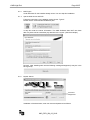
Insert the delivered setup CD ROM into your CD ROM drive.
If the High End Installer should not launch itself after a short period, open it
manually by entering the path of your CD-ROM drive into the command
line of your windows explorer and selecting the launcher.exe file on the
CD-ROM.
The installation menu will pop up:
Depending on your system performance the installation can take several minutes. Pay
attention that each action is finished properly (confirmation notice) before starting the
next one. Finally leave the installation menu by clicking on the close button and restart
your PC. (Power off!)
LMS_RFH_BA_02_0912
OMS High End
6.1.3.
Page 22/57
MSI Engine
Under Windows XP this installer already exists. You can skip this installation.
6.1.4.
Apache Web Server and PHP
Follow the instructions. As installation mode choose “Typical".
Please use the recommended installation path.
In step four enter the server information. The OMS Software does NOT use these
data. Any data can be entered but pay attention to the syntax. (See the example).
Remark: After installing wait until the following message disappears (it may be in the
back-ground).
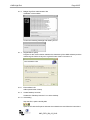
6.1.5.
MySQL Server
Password:
badger1981
Installation of the data base, enter user name and password as follows.
LMS_RFH_BA_02_0912
OMS High End
6.1.6.
Page 23/57
Badger High End Administration Site
Installation of the website.
Confirm the following message and restart your PC.
6.1.7.
Keypad Server (KPS)
Program for the communication between the data base (of the OMS software) and the
master keypad. Select “everyone“ to give all users of the PC access to it.
6.1.8.
Execute Batch file
Adds special folder C:\temp
6.1.9.
Create Desktop Launcher
Creates the "Desktop Launcher" icon at the desktop.
6.1.10. Uninstalling
Stop the KPS, Apache and MySQL
Open the CD with the Explorer and start the uninstaler.exe and follow the instructions.
LMS_RFH_BA_02_0912
OMS High End
Page 24/57
6.2. System configuration
The following steps are necessary to set up the OMS High End system properly.
In the setup menu (chapter 6.5):
1.) Common settings like location, unit of measurement and language.
2.) (Process-) technical parameters of the keypads like time out, status reports, optional
functions and the miscellaneous WO.
In the entity menu (chapter 6.6):
3.) Creation of the hardware components in the system
4.) Creation of users/mechanics in the system
In the tree menu (chapter 6.7):
5.) Assigning and linking the entities to each other
In the entity menu (chapter 6.6):
6.) Entering the actual tank levels
By using the KPS software (chapter 7):
7.) Transmit the configuration settings to the master keypad with the KPS Software
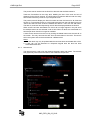
6.3. First start of the OMS software
To launch the software, click on the link on your desktop or enter http://localhost into the
command line of your Internet Explorer.
Enter the 4-digit system password and click the LogOn button.
The system password is initially set to 0000 (four times zero).
LMS_RFH_BA_02_0912
OMS High End
Page 25/57
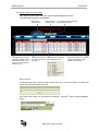
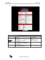
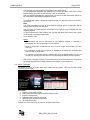
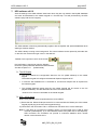
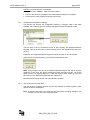
6.4. Menu: Report by work order
The report by work order will show all the finished dispense results.
The following functions are available:
Will refresh the
current screen.
Will print the
current screen.
The filter will give you the
possibilty to select only the
desired information. The
result can be exported to
EXCEL (*.csv).
The number of items
you would like to see
per page.
The current list will be exported,
see description below.
Additional information for
each dispense result.
Will sort the data by the selected
column, indicated by a grey
triangle in the header.
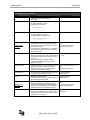
Export function:
The Export button will create from the selected list a file (*.CSV ASCII-Code). A window will
inform you about the location of the file.
The folder Export folder can be opened by selecting: Windows® START-Programs-BadgerExport
LMS_RFH_BA_02_0912
OMS High End
Page 26/57
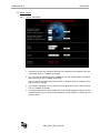
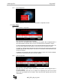
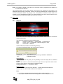
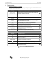
6.5. Menu: Setup
6.5.1.
System initialization
1. Change the system PC Password. Enter the new password and repeat it in the box
underneath. Click on “Validate” at the right.
2. You can choose between Europe (868MHz) and the United States (915MHz).
After changing click on “Validate” at the right.
The unit can be changed from LITER to PINT or QUART. Click on “Validate” at the
right to save the change.
3. The software language can be chosen from the drop down menu. After choosing
click on “Validate” at the right.
4. In this line date and time of the system and of the master keypad are shown. If they
are differing strongly you should compensate them (see chapter 3.3 “Menu INI: set
date and time“).
LMS_RFH_BA_02_0912
OMS High End
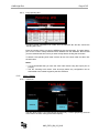
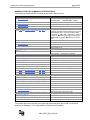
6.5.2.
Page 27/57
Configuration
Parameters Master Keypad
Label
Database
Comments/rules
Keypad timeout
• Master keypad timeout for communications
with the PC.
• If this timeout occurs, the dispense keypad
with display the error message:
"Master down”
Enter a decimal value from
15 – 255.
One second increments.
Default is 20 seconds
External printer
RS232
• In the menu REP you can create reports
sorted by WO, User, and Product etc.
See chapter 3.6
YES/NO selection.
Buzzer
• A beep will sound after every button press on
the master keypad keyboard.
YES/NO selection.
Should not be
changed!
LMS_RFH_BA_02_0912
OMS High End
Page 28/57
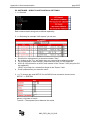
Parameters Dispense Keypad
Label
Database
Comments/rules
Mileage type
• Defines the unit for the N Field.
km / Miles
Km/Miles selection
N Field info
• This field will appear on the dispense keypad YES/NO selection
for every dispense request.
8 digit numeric free field
Free Numeric
-------AN Field
• This field will appear on dispense keypad
for every dispense request.
10 digit alphanumeric free field
YES/NO selection.
Free Alphanumeric.
---------Timeout
Should not be
changed!
• This timeout is the amount of the dispense
keypad sit idle (no buttons pushed) during
the dispense request process prior to return
to the main screen.
• If this timeout is reached prior to completing
the request the USER must re-enter PIN to
begin WO request.
Enter a decimal value from 10255.
One second increments.
Default is 10 seconds.
Top off timer
Enter a decimal value from
• The hose inactive timeout controls the
amount of time the hose may sit idle before it 0 – 900.
automatically closes out the work order and
lock-out.
• This time begins on the hose when it
receives the dispense quantity from the
dispense keypad.
Display timeout
• Controls the amount of time the fluid name is
displayed during the dispense process.
• Pressing the Enter key on the dispense
keypad will override this timeout.
Enter a decimal value from 0 –
900.
Default is 600 seconds.
Internal printer
• The dispense keypad will automatically print
a receipt of each dispense result.
YES/NO selection.
Default is NO.
Buzzer
YES/NO selection.
• Dispense keypad buzzer.
• A beep will sound after every button press on Default is YES:
the master keypad keyboard.
Keypad timeout
• Controls the time how long the dispense
keypad will wait for the master keypad to
send an acknowledgment a request/result. If
this timeout is exceeded an error message
will be displayed in the dispense keypad.
Enter a decimal value from 1 –
255.
One second increments.
Default is 30 seconds.
• Under the specified number the user can
always start a dispense. Even if the master
keypad is switched off or PC / HOST are not
replying for some reason.
Enter six alphanumeric
characters.
Should not be
changed!
Miscellaneous WO
LMS_RFH_BA_02_0912
OMS High End
6.5.3.
Page 29/57
Host configuration
The configuration of the host protocol is described in a separate manual.
6.6. Menu: Entity
6.6.1.
Fluid / Product configuration
Up to 16 fluids can be defined in the system.
The fluid id is a two-digit number controlled by the system and is assigned when a
new fluid is added. The fluid name can up to 16 alphanumeric characters in length.
To add a new fluid type the fluid name in the new fluid label box and click create. The
new fluid will be added and will appear on the screen next to its fluid ID number.
To modify an existing fluid name type the new name in the box next to the one to be
modified and click the modify button. The name of a fluid that is associated with a tank
cannot be changed.
To delete a fluid check the box next to fluid you wish to remove and it will be deleted.
A fluid that is associated with a tank cannot be deleted.
6.6.2.
Tank configuration
Up to 16 tanks can be defined in the system.
The tank id is a two-digit number controlled by the system and is assigned when a
new tank is added.
To add a new tank, select the unit of measure for dispensing from the new unit pull
down menu just below the list of tanks. Then enter the tank capacity and click the
create button.
LMS_RFH_BA_02_0912
OMS High End
Page 30/57
To change the current level of a tank, type in the level in the new level box and click
modify. The actual level of the tank can be updated only after the tank has been
associated to a fluid.
To delete a tank click on the delete box next to the tank to be remove and it will be
deleted. A tank that is associated with a fluid cannot be deleted.
6.6.3.
Hose (Meter) configuration
Up to 250 meters can be defined in the system. Hose and meter are synonymous
terms. The hose Id is a four-digit number controlled by the system and is assigned
when a new meter is added.
The meter address is found on a tag inside the battery compartment of the meter. The
format of the address is x.xxx.xxx.xxx and is a 10-digit number. When the address is
entered the decimal points must be entered in the correct position as found on the
address tag.
To add a meter to the system, enter the meter address in the new hose address box
and click the create button. The system will assign the hose id number automatically.
To delete a meter click the delete box next to the meter to be removed from the
system. A meter that is associated in the network tree cannot be deleted.
6.6.4.
Dispense keypad configuration
Up to 32 dispense keypads can be defined in the system.
The dispense keypad id is a four-digit number controlled by the system and is
assigned when a new keypad is added.
The keypad address is found on a tag on the backside of the keypad. The format of
the address is xx.xx.xx.xx an 8-digit number.
Keypad address
When the address is being entered the decimal points must be entered in the correct
position as found on the address tag.
To add a keypad to the system enter the keypad address in the new dispense keypad
address box and click the create button. The system will assign the keypad ID number
automatically.
To delete a keypad, click on the delete box next to the keypad to be removed from the
system. A keypad that is associated in the network tree cannot be deleted.
LMS_RFH_BA_02_0912
OMS High End
6.6.5.
Page 31/57
User configuration
The purpose of this screen is to manage user information for the system. From this
screen you can add and delete a user or update current user information. The system
can have up to 250 users with User ID 1 being reserved for the supervisor PIN ID. The
supervisor PIN ID is used for access to management screens on the master and
dispense keypads.
To create/add a new user to the system, in the box next to NEW User, type in the user
name and the desired pin number and click create.
• The PIN ID number has four-digits. Leading zeros must be included.
• The user name can be up to 16 characters in length.
• Note: 8888 is a reserved PIN ID and cannot be assigned to a user.
To delete a user click the delete box next to the user to be deleted and the user will be
removed.
The user will be deleted when the box is checked.
CAUTION: To modify an existing user name, enter the information into the new user
name box next to the name to be changed and click the modify button.
To change a user password, enter the new password in the PIN ID box of the one to
be changed and click modify.
CAUTION: Changing of a user password requires that the system be updated through
the “Send User” function from the KPS system (see chapter 7 „KPS software“).
6.7. Tree menu
6.7.1.
Tree product
LMS_RFH_BA_02_0912
OMS High End
Page 32/57
The product tree is used to link the fluid ID to the tank that the fluid resides in.
Tanks are first defined in the entity tank, detailing the size of the tank and unit of
dispense for the fluid in the tank. The fluid types must also be defined under the entity
fluid screen before they will show up in the product tree.
The product tree will display the fluid ID number and the fluid name for all fluids that
are set up. To associate a tank to a fluid, select the tank from the pull down list next to
“Add a tank with this fluid" under the desired fluid branch. Then click the add button.
The tank ID, tank level and dispensing unit will then be displayed below the fluid ID.
When a tank has been associated to a fluid it will no longer appear in the pull down
list. Multiple tanks can be selected under a fluid. When all tanks are associated to a
fluid the pull down list will no longer be available.
A tank can be removed from the tree by clicking the delete button next the tank ID on
the screen. This only removes the tank from the association to the fluid. The tank is
still in the system and can be associated to a different fluid.
Notes:
1. The tank level may only be updated after the tank has been associated with a fluid.
2. A tank can only be attached to a dispense keypad after the tank has been
associated with a fluid.
6.7.2.
Network tree
The network tree is used to link the dispense keypads, tanks and meters. The network
tree graphically shows the association of the hardware components.
LMS_RFH_BA_02_0912
OMS High End
Page 33/57
The first step is to add all dispense keypads to the network tree.
To add a dispense keypad to the network tree, use the pull down next to the “Insert
Dispense Keypad” on the screen and then click the add button.
After the dispense keypads are selected the next step is to select the tanks that are to
be associated to the individual dispense keypad.
To select a tank under a dispense keypad use the pull down list next to the insert a
tank branch.
Note:
You must associate each tank to each dispense keypad where a hose/meter will be
used to dispense fluid from that tank.
The next step is to associate the hose/meter that is going to be accessed from the
dispense keypad.
To add a hose/meter to the network tree, use the pull down next to the insert a hose
on the screen and click the add button.
Cont. Network Tree
Notes:
9 A hose/meter can only be associated to one dispense keypad. In operation a
hose/meter can only be selected from this keypad.
9 When a component is selected from a list it will no longer be included in the pull
down list.
9 In accordance to that if no component is available to be added, the according pull
down list will not be present.
9 To remove a component from the network tree click the delete button next to it. It
will only be removed from the tree but not completely be deleted from the system.
After having changed anything at the network tree you must transmit the changes to
the master keypad with the KPS-Software (see chapter 7 „KPS software“).
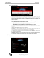
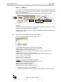
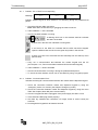
6.8. Menu: Dispense
The dispense screen is used to enter work orders into the system. This would be the normal
operation screen used.
If this error
occures, you have
done changes to the
configuration without
sending them to the
system with KPS
(“Init”)
See chapter 7.2.4
Operation:
1. Enter the work order number
2. Select the desired fluid type from the pull down menu
3. Enter the fluid quantity
4. Optional Enter N-Field (if activated)
5. Optional Enter AN-Field (if activated)
6. Click the send button
To abort the work order entry in process, click the reset button.
LMS_RFH_BA_02_0912
OMS High End
Page 34/57
Note: The quantity is based on the tank unit. The meter must be programmed to dispense in
the same unit as the tank.
The queuing feature of the system allows work orders to be entered into the system to be
dispensed at some point in the future. There is no need to pre-determine or select the hose to
be used for dispense before it is going to occur. The operator will select the work order to be
worked on from the dispense keypad. The hose selected at that time will be verified for the
correct fluid and the dispense quantity will be sent to the meter.
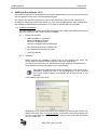
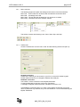
6.9. Menu: File
6.9.1.
Setup file
Browse …
In this menu item the configuration setup can be saved in a file as well as saved files
can be re-accessed.
The saved file contains the following parameters:
Setup
> System configuration > Configuration > Host Protocol
Entity
> Fluid> Tank > Hose/Meter > Dispense Keypad > User
Tree
> Fluid-Tank > Network
All saved files are located in the following directory:
C:/Program files/Badger/High-end Admin/High End/Export/
Example file: Setup_190309202446.2_21.
091003132747
-> Date and time of the storing in DDMMYY HHMMSS
.2_21
-> Database version
Save setup file:
The underlined blue link gives you the possibility to save the setup file to a different
location.
Move on the curser on the link and click the right mouse to open the context menu.
Choose “Save target as” and select the desired location.
Change file format to “*.*” and click on “Save”.
Open setup file:
To access a saved file click on the “Browse…” button and select the setup file.
Click on open in order to load the file into the database
Note:
9 It is highly recommended to save the setup file to another location.
9 If you open a stored file the actual settings will be irrecoverably overwritten.
LMS_RFH_BA_02_0912
OMS High End
6.9.2.
Page 35/57
Pending work orders file
Browse …
In this menu item the saves pending work orders in a file as well as saved files can be
reaccessed. The underlined blue link gives you the possibility to save the setup file to
a different location.
Note: If you open a stored file, the actual settings will be irrecoverably overwritten.
The file will be saved as:
C:\Program files\Badger\HighEnd admin\High_End\Export\ongoing***.2_21
6.9.3.
Closed work orders file
Browse …
In this menu item the saves work orders in a file as well as saved files can be reaccessed. The underlined blue link gives you the possibility to save the setup file to a
different location.
Note: If you open a stored file, the actual settings will be irrecoverably overwritten.
The file will be saved as: C:\Program files\Badger\HighEnd
admin\High_End\Export\wo***.2_21
LMS_RFH_BA_02_0912
OMS High End
6.9.4.
Page 36/57
Database file
Browse …
In this menu item the saves whole database in a file as well as saved files can be reaccessed. The underlined blue link gives you the possibility to save the setup file to a
different location.
The file will be saved as: C:\Program files\Badger\HighEnd
admin\High_End\Export\db***.2_21
The saved file contains the following parameters:
Setup
> System configuration > Configuration > Host Protocol
Entity
> Fluid> Tank > Hose/Meter > Dispense Keypad > User
Tree
> Fluid-Tank > Network
WOs
> Pending WOs > Closed WOs
Note: If you open a stored file, the actual settings will be irrecoverably overwritten.
6.9.5.
Export file
Here you can create a data file which can be imported by spreadsheets, word
processors or databases. The underlined blue link gives you the possibility to save the
setup file to a different location.
The format is an ASCII-Code (*.csv).
Export file example:
The export file will be saved as:
C:\Program files\Badger\HighEnd admin\High_End\Export\export*.csv
LMS_RFH_BA_02_0912
OMS High End
6.9.6.
Page 37/57
Purge pending WO
In order to purge completed work orders from the REPORT BY WO list, choose the
“Pending WO” menu
Enter the number of days you wish to KEEP and click the OK button. The order history
prior to this number of days selected will be deleted from the database. Be sure that
you have selected the time frame you want to keep before clicking the OK button.
To delete a sole pending work order click the id box of the work order and then click
the OK button.
Notes:
9 It is recommended that you save the work order results using file export prior to
purging.
9 The list: “Pending work orders” must be empty before any configuration can be
transmitted to the master keypad by the KPS software.
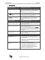
6.10.
Menu: Display
6.10.1. Tank level
The tank level screen is for informational purposes only. It shows graphically the level
of the fluid in the tank, fluid type and tank capacity.
LMS_RFH_BA_02_0912
OMS High End
Page 38/57
6.10.2. Fluid usage
The fluid usage screen is for informational purposes only. It shows graphically the total
volume of fluid available. For example, if two tanks have the same fluid, the tank
capacities are summed and the percentage of fluid available is based on the summed
value.
6.10.3. Pending WO
The pending work order screen shows all of the work orders in the systems that are
available to be selected. After a work order is completed the work order will be
removed from pending WO and the dispense results will be added to the work order
history file. Work order history can be accessed by clicking on the LOGO in the upper
left corner.
6.11.
Menu: Report
6.11.1. Report initialisation
LMS_RFH_BA_02_0912
OMS High End
Page 39/57
This display provides an overview of the system entity and the associated data.
The first section shows the relationship of the tank Id to the fluid type, the quantity in
the tank along with the unit of measurement.
The second section shows the ID of the dispense keypad and the hose/meter ID
numbers. It also shows the fluid dispensed from each hose/meter.
The third section shows the system users and their four-digit pin ID number.
No data can be modified from this screen.
To return to the main menu options, click on the Badger LOGO in the upper left
corner.
6.11.2. Configuration
This display provides an overview of the system configuration data.
No data can be modified from this screen.
To return to the main menu options, click on the LOGO in the upper left corner.
6.11.3. Work order
This display provides an overview of the closed work orders. The sorting can by
defined by clicking on the headline of the column you want to sort by. By clicking on
the head line a second time, the sorting order will be turned over.
Choosing the criteria from the drop down menu will sort the list by the selected criteria.
Set the period you want to for the data to be shown.
To return to the main menu options, click on the Badger LOGO in the upper left
corner.
LMS_RFH_BA_02_0912
KPS software v0.5.2
page 40/57
7. KPS software v0.5.2
After the settings in the OMS software have been done, they are only stored in the MySQL database
and must be transmitted to the master keypad in a second step. This will performed by the KPS
software (Key Pad Server Program).
The KPS software is launching automatically together with the MySQL and Apache databases when
starting a windows session.
The KPS is always running in the background. The control window can be opened by a double click
on the KPS icon at the lower right corner in the task bar.
Taskbar in the right lower corner of the screen
PIN verification is required to open the Window.
Enter the system password defined the OMS software.
See also chapter 6.5.1 (Default 0000).
7.1. The KPS tasks
• The KPS transmits the configuration data from the PC (OMS software) to the master
keypad
The master keypad will configure the attached dispense keypad via RF.
• In case the “WO Validation PC” is switched on, the KPS will respond the oil request from
the master keypad.
• The finished dispense results send by the master keypad will be stored on the PC
(MySQL database). See also REPORT BY WO in the OMS software.
“Archive on PC” has to be activated on the master keypad.
7.2. KPS - a first check
Before using the KPS some requirements have to be fulfilled:
1) Ensure that the RS232 COM port at the PC is connected with the RS232 port of the master
keypad (9 pole plug at the front side keypad housing).
2) Check that in the KPS under “Edit >> Preferences“ has been set to correct COM port.
Note: In case there is not COM Port available. We do not recommend using a USB to serial
converter (USB adapter), try to use instead a RS232 card (either PCI or PCI-Express).
USB converters can sometimes not provide a continuous dataflow which causes
random communication errors.
LMS_RFH_BA_02_0912
KPS software v0.5.2
7.2.1.
page 41/57
Menu overview
The following pages will explain the settings and functions of the KPS software.
Menu File
Menu Edit
Menu View
Menu Help
Protocol files can be stored and the software can be shut down.
All settings are made.
The tool bar and the status bar can be shown or hidden.
Information about the software release
The tool bar contains the following icons: Save, Start, Stop, and Help
7.2.2.
Preferences
Choose "Preferences" from the menu “Edit“ and the following window will open up:
Keypad connection:
Choose the COM port you have used on your PC to connect the master keypad.
Please restart the KPS if you changed to different the COM port.
Database connection:
You ensure a correct connection to the MySQL data base.
To test the data base connection click on the Test button.
A message will appear ahead the button: Database connection: OK
If the database connection failed, you have most probably entered the wrong user
name or password. Pay attention, they are case sensitive. You had entered during the
MySQL installation.
LMS_RFH_BA_02_0912
KPS software v0.5.2
page 42/57
User:
badger
Password: badger1981
In case you have double check the entered data, click on the MySQL database icon
and choose “Show me”. Select the tab “my.ini Setup”. Change data if necessary and
click on “Save Modification”.
Select the Environment tab and click on “Hide me” to close the MySQL window.
Log file:
The log file will help to evaluate a communication problem as it provides an archive
the KPS communication over the specified time.
The path can be defined, default is C:\Program files\Badger\KeyPad Server\KPS\logs.
The file format is *.rtf.
7.2.3.
Test communication between KPS and master keypad
Choose "Test communication" from the menu “Edit.
A successful communication will show the following lines:
03/20/09 19:06:44 : Flow #60 : Sending a communication test : Ok
03/20/09 19:06:44 : Sending frame : 02 60 61 03
03/20/09 19:06:44 : //////////////// [ trame n°60 | Octets emis : 1442 | Octects utile : 1442 ]
/////////////////
03/20/09 19:06:44 : Reading frame : 02 61 00 62 03
03/20/09 19:06:44 : Flow #61 : Receiving first acknowledge of Communication Test : Ok
03/20/09 19:06:44 : Starting listener
03/20/09 19:06:44 : Listener is down
03/20/09 19:06:44 : Starting listener
Problem 1: The master keypad does not respond.
03/20/09 19:15:23 : Flow #60 : Sending a communication test : Ok
03/20/09 19:15:23 : Sending frame : 02 60 61 03
03/20/09 19:15:33 : Timeout error number 0
03/20/09 19:15:33 : Waiting 2 seconds ...
03/20/09 19:15:35 : Trying to resend last frame [1 / 6]
• Check that the cable is properly connected
• Ensure that the master is up and running, you may reboot the master just in case.
LMS_RFH_BA_02_0912
KPS software v0.5.2
page 43/57
Problem 2: The serial port is not available.
03/20/09 19:21:35 : ERROR : Serial connection failed.
• Check in the windows hardware menu if the selected COM port is available
• Ensure that no other program is using the same port.
7.2.4.
Init (transmit configuration settings)
This function will transmit the configuration settings or changes made in the OMS
software, the master keypad will configure the attached dispense keypad via RF.
The first step in the init procedure will be to lock remotely the attached dispense
keypads. This will ensure, that no will accidently start a new dispense while the init is
running.
Important: All configured dispense keypads must be switched on and accessible.
When the init has been finished, you will see the following window:
Note: It may happen, that one of the attached dispense keypad has still an ongoing
dispense. In this case, the above mentioned locking procedure will fail. You would
need to finish the ongoing dispense or clear the ongoing work orders by using the
MET menu in the dispense keypad (see also chapter 4.4).
Red lines and a pop up window will mark indicate a problem.
7.2.5.
User (Transmit only user data)
Use this function is used to transmit only the user settings to master keypad in order
reduce the time of initialisation.
Note: To prevent interrupts in the work flow we recommend changing settings in the
evening or in low commerce volume periods.
LMS_RFH_BA_02_0912
Troubleshooting
page 44/57
8. Troubleshooting
8.1. Dispense keypad error messages
These error messages can be displayed by the dispense keypad. The associated action to
reset the system is listed behind.
Message
Hose active
hit hose reset
Messages at the dispense keypad
The selected meter currently has a dispense order in waiting to be
processed, complete the active order.
WO
refused
The entered work order number is not valid and has been refused by host
or OMS software.
Master
is down
The master does not respond to a request from the dispense keypad
PC
is down
The OMS software (KPS) is not responding to the master keypad.
Only if WO validation PC is activated.
HOST
is down
The HOST (DMS) is not responding to the master keypad.
Only if “WO Validation HOST” is activated.
Host or PC is
occupied
Wrong hose
for fluid
RF communication
Message
Master keypad is occupied by another job.
The meter selected is not a valid meter for the
fluid assigned for this WO.
Communication is in progress, please wait (10 sec).
Messages at meter
F1
An error occurred during the RF transmission.
F2
The RESET button has been pressed and no response arrived
within 12 sec - timed out.
Display flashes
A pulse error occurred during the dispense,
only valid for PTB version.
RF communication is in progress, please wait (10 sec)
HISTORY
A dispense result could not be sent and has been saved in the
"Out of Sequence" memory.
Press once more the RESET button at the meter
LMS_RFH_BA_02_0912
Troubleshooting
8.1.1.
page 45/57
Problem: PC or HOST is not responding
Message
Master
down
HOST
down
PC
down
Problem: Master keypad or Host (DMS) is not answering during the predetermined
period.
1. Check the RS-232 cable connection.
Note: Shut down the PC before (un-)plugging the cable connector.
2. If WO-validation >> PC is activated
9 Check if the KPS software is running
A differing KPS icon in the windows task bar indicates
the status of the KPS
A green dot in the KPS icon indicates a running KPS.
A red cross on the KPS icon indicates that the KPS has been stopped.
Open the KPS window and click on the green key button in the tool bar.
If there is no KPS icon at all start the KPS manually from the start-up menu
(launch KPS)
9 Carry out a communication test between the master keypad and the PC
(see chapter 7.2.3 „Test communication between KPS and master keypad“)
3. If WO-validation >> Host is activated
9 Check if the host answer is coming in during the predetermined period.
9 To check the host interface a host can be simulated by using a keypad program.
8.1.2.
Problem: "Communication Error"
Indicates a missing RF communication between the master and the dispense keypad.
1. Check the connection between master and dispense keypad by using the
“emergency mode >no” function (see chapter “Emergency mode“).
2. Check the connection between master and dispense keypad by using the menu
TRM. See chapter „Menu DK (test communication)“.
3. Check if a keypad has been unplugged / if the power supply has been cut off.
4. Is the antenna’s BNC plug locked properly?
5. Are there any obstacles like containers, roll cages, buses or trucks nearby the
antenna?
6. De-energize the keypads for at least 20 seconds.
LMS_RFH_BA_02_0912
Troubleshooting
page 46/57
8.2. Other problems
Problem – RF Meter
Description and error recovery
F02 on the main display
The meter did not get a reply from the dispense keypad. This
may happen, because another meter is sending data in this very
moment or the dispense keypad is communicating with the
master.
Press 2xRESET start the communication again.
The AUTO function is shut off; the
AUTO icon disappeared and cannot
be activated again.
The battery sign is flashing in the lower left corner. This means
the battery power is too low to run the auto function. The meter
can still run in manual mode. Change the batteries.
It is not possible to set back the meter
from AUTO mode to standard preselection mode.
For a new installation, check if the RF-ID number is correct.
For a running installation, send an “Init” to reinitialise the
database in the dispense keypad (see chapter 7 “KPS
Software”).
Problem – Keypad
Description and error recovery
Message at the master keypad:
„Order List not Empty not empty“
The master keypad stores transaction sorted by date and time.
Due to this, you have to “Clear Transactions” (CNF menu) first
and then change date and time.
The screen shows only “Reloading
Parameter” and does not proceed.
Data database of the keypad is most likely corrupted; this may
happen due a bad power supply line.
To resolve this, power down the keypad and press and hold the
button 1 and 2 until you see “Confirm erase”. Choose YES and
perform a memory erase. At the end of this process you have to
reboot the Keypad and send an “Init” over the KPS to initialise
the data again.
Random Communication Errors on
the dispense keypad.
The RF-Signal seems to low; perform the LNK test to check the
link quality. You can various types of remote antennas to
improve the signal strength.
Problem – OMS KPS software
Description and error recovery
No actual dispense data are shown
in the OMS software.
9 Check if the Archive on PC is activated in the Master.
9 Click on the Badger Logo in the upper left corner to refresh
the work order list.
9 Carry out 7.2.3 “Test communication between KPS and
master keypad“. Transactions that have not reached the PC
yet, will be transmitted.
KPS, “Init” stops with red error
message.
9 Check first if the master keypad responds.
See chapter 7.2.3 “Test communication to the Master”
9 Check if all dispense keypads are powered on.
9 Check if there is no ongoing dispense in a dispense
keypad”. Use the menu MET to remove pending WOs.
See chapter 4.4 “Delete prepared WO”
LMS_RFH_BA_02_0912
Worksheets
page 47/57
9. Worksheets
Fluid ID
Fluid Name
1
2
3
4
5
6
7
8
9
10
11
12
13
14
15
16
A maximum of 16 products.
The alphanumeric name, max. 16 characters.
Tank ID
1
Fluid
Tankvolume
2
3
4
5
6
7
8
9
10
11
12
13
14
15
16
Maximum 16 Tanks.
Tank volume format: 00000.000.
LMS_RFH_BA_02_0912
Unit
Content
Worksheets
Keypad ID
page 48/57
Adress xx . xx . xx . xx
1
2
3
4
5
6
7
8
9
10
11
12
Max. 12 dispense keypads.
RF keypad address is an 8 digit number.
Meter ID
Adress x . xxx . xxx . xxx
1
2
3
4
5
6
7
8
9
10
11
12
13
14
15
16
17
18
19
20
21
22
23
24
Max 99 meters/hoses.
The address is a 10 digit number.
LMS_RFH_BA_02_0912
Worksheets
page 49/57
Dispense Keypad ID 1
Fluid
1
Tank ID
meter number
Tank ID
meter number
Tank ID
meter number
2
3
4
5
6
7
8
9
10
Max. 24 meters per keypad.
Dispense Keypad ID 2
Fluid
1
2
3
4
5
6
7
8
9
10
Dispense Keypad ID 3
Fluid
1
2
3
4
5
6
7
8
9
10
LMS_RFH_BA_02_0912
Worksheets
page 50/57
User ID
Name User
Supervisor
1
2
3
4
5
6
7
8
9
10
11
12
13
14
15
16
17
18
19
20
21
22
23
24
25
26
27
28
29
30
31
32
33
34
35
36
37
38
39
40
41
42
43
44
45
Up to 250 users. The user field is alphanumeric, max. 16 characters.
The user PIN ID is a 4 digit number.
LMS_RFH_BA_02_0912
PIN ID
0000
Appendix I: Host communication
page 51/57
10. Appendix I: Host communication
The direct connection between host computer and RF system will be established through a
serial interface RS232 (V24) at the Master Keypad (MK) based on ASCII code.
STANDARD COMMUNICATION
• The RF system will verify an entered work order number by sending it to the host
computer.
• The host computer will check the work order number and will refuse or send a
permission.
• Once the transaction is done, the RF system will send the collected data to the host
computer.
• The host computer will send a receipt acknowledgement to the RF system.
ADDITIONAL POSSIBILITIES
• The communication strings can be edited through the PC software. The field definition
and sequence are free adjustable.
• Start and end of data field can be defined (ASCII code).
• Data field separator can be defined (ASCII code).
• If the host computer is not available, a miscellaneous work order number can be
entered.
• The retry time, until the RF system will try to resend, and the total retries are
changeable.
• All transactions which could not be sent will be tagged and resent as soon as the host
computer is reconnected.
• When a work order request has been sent, the host computer can specify the following
items in his reply:
- Product ID
Network
- Quantity
Host
- Product name
Server
- Alphanumeric field, for example license plate
- Numeric field, for example odometer
1x
12x
Dispense
keypad
Master
keypad
Terminal (PC)
24x
Meter
hose
LMS_RFH_BA_02_0912
Appendix I: Host communication
page 52/57
EXAMPLE FOR THE COMMUNICATION PROTOCOL
The following communication is based on the default host protocol.
>A12345678901<
Standard communication (sample)
RF System is sending job request
Is work order "12345678901" valid ?
>J12345678901<
>N12345678901<
Answer Host: Yes, valid!
Or answer: No, not valid!
>D1046003212345678901052701 0353 <
RF-System is sending the WO result to the host
computer. Description: D1 indicates this is the WO
result, 046 Day of the Year (15.02.2002), 0032
Transaction n°, 123... WO n°, 527 PIN n°, 01 Hose
or meter n°, Blank This is an approved dispense,
0353 Quantity 3,53 liters, Blank Send for first the
time.
>J12345678901<
>N12345678901<
OK, WO result received!
WO result refused!
>A1234
>N1234
New request for oil
Host computer answers - NO
The local display will show for short moment,
"WO refused" - No dispense is possible
<
<
Other possible scenarios
>A12345678901<
>A12345678901<
>A12345678901<
>J12345678901<
Request for oil from RF-System
>D1046003212345678901052701 0353 <
>D1046003212345678901052701 0353#<
>D1046003212345678901052701 0353#<
>D1046003212345678901052701 0353#<
>D1046003212345678901052701 0353#<
>D1046003212345678901052701 0353#<
>D1046003212345678901052701 0353#<
>D1046003212345678901052701 0353#<
>D1046003212345678901052701 0353#<
>D1046003212345678901052701 0353#<
After the dispense the data arriving at the host
... in total 10 times each 5 sec (default)
>A123456ABCEF<
>J123456ABCEF<
New request for oil
Host computer answers - OK
>D1046003212345678901052701 0353#<
>J12345678901<
The old transaction will be sent again.
Host computer accepts the data
>D10470033123456ABCEF821501 0150 <
>J123456ABCEF<
The new data will be sent now ...
OK, acknowledged
.. again each 5 sec. (default)
Host computer anwers - OK
..
After 10 retries it will stop = timed out
To simulate the host computer during the test period we have found, that the terminal
program of Windows 3.11 is very helpfull. Can be sent on request.
LMS_RFH_BA_02_0912
Appendix I: Host communication
page 53/57
PC SOFTWARE - SPECIFY HOST PROTOCOL SETTINGS
1. >>> Choose
Each communication string can be defined separately.
2. >>> Selecting for example "WO request" you will see
●
●
●
●
●
Each field is represented by a sequence number "Seq.".
By clicking on the "Fct." pull down menu you can see the available functions.
For more details on each function, please see also point 4 of this appendix.
ASCII [0-126] will ask for an ASCII code number in the "Param." field (see point 5 of
this appendix)
LEN [1-xx] will ask for a certain field length in the "Param." field.
Press update before you leave the menu.
3. >>> To change the serial SETUP for the RS232 host connection choose menu
SETUP >> SYSTEM
Nbretry = Number of retries
Timeout = The elapsed time in-between the retries
LMS_RFH_BA_02_0912
Appendix I: Host communication
page 54/57
4. >>> FUNCTIONS - Field definitions
No
0
1
Function
END
FILTER
2
3
QUOTE
ASCII [0-126]
RETRY CHAR ASCII [0-126]
ASCII
ASCII
4
CHECKSUM
FIX
-
11
USERNAME
LEN [1-16]
Length
12
PIN ID
FIX
4 Char.
21
22
23
24
25
26
27
YEAR
MONTH
DAY
DAY OF YEAR
HOUR
MINUTE
SEC
FIX
FIX
FIX
FIX
FIX
FIX
FIX
41
FIX
LEN [1-255]
Type
Length
Description
Field not defined
A blank field (=spacer) might be
needed to adapt to certain prot.
Creates a character
This field is blank for the first
transmission. Any other
transmission will show the defined
ASCII character.
Binary checksum
Can be used in
○ ○ ○ ○ ○ ○
- ○ ○ ○ ○ ○
○ ○ ○ ○ ○ ○
○ ○ ○ ○ ○ ○
○ ○ ○ ○ ○
The entered user, entered with the
PIN ID
The entered user at the dispense
keypad
○ -
-
○
-
-
○ -
-
○
-
-
4 Char.
2 Char.
2 Char.
3 Char.
2 Char.
2 Char.
2 Char.
Format
Format
Format
Format
Format
Format
Format
-
-
○
○
○
○
○
○
○
-
-
WO NO
LEN [1-16]
or JOB NO (old)
TRANSACTION NO LEN [1-4]
Length
The entered work order number
○ ○ ○ ○ ○ ○
Length
-
2 Char.
44
45
46
47
48
DISPENSE KEYPAD ID FIX
or SLAVE KEYPAD ID (old)
HOSE ID
FIX
PRODUCT NAME LEN [1-16]
PRODUCT ID
FIX
TANK ID
FIX
FREE FIELD 1
LEN [1-8]
2 Char.
Length
2 Char.
2 Char.
Length
49
50
51
52
FREE FIELD 2
LEN [1-16]
DISPENSE INT
LEN [2-3]
DISPENSE DEC LEN [2-3]
DISPENSE STAT ASCII [0-126]
Length
Length
Length
ASCII
Incrementing number, each
transaction has a unique number.
Format 0001 to 99999
Gives the dispense keypad ID
were the dispense was made.
HOSE ID or meter ID (01 to 99)
Alphanumeric field
Format 01 to 16
Format 01 to 16
Numeric field to be activated
under Setup >> Configuration >>
Dispense Keypad
Alphanumeric field, same as above.
Integer part of quantity
Decimal part of quantity
This field is blank if dispense was
an approved dispense. On any
error it will show the defined character.
LMS_RFH_BA_02_0912
-
-
○
-
-
○ -
-
○
-
-
-
-
○
○
○
○
○
-
-
-
-
○
○
○
○
-
-
WO-KO
WO-RESULT
WO-RESULT OK
WO-RESULT KO
-
WO-OK
43
Date and
time of WO
result >>
when it
arrives at the
Master
Keypad.
-
WO-REQUEST
42
YYYY
MM
DD
001to 365
HH
MM
SS
-
○
○
-
○
○
○
○
Appendix I: Host communication
page 55/57
5. >>> ASCII-Code Chart
Dec.
Char
Dec.
Char
Dec.
Char
Dec.
Char
001
[SOH]
002
[STX]
033
!
065
A
097
a
034
"
066
B
098
b
003
[ETX]
035
#
067
C
099
c
004
[EOT]
005
[ENQ]
036
$
068
D
100
d
037
%
069
E
101
e
006
[ACK]
038
&
070
F
102
f
007
[BEL]
039
008
[BS]
040
´
071
G
103
g
(
072
H
104
h
009
[TAB]
041
)
073
I
105
i
010
[LF]
011
[VT]
042
*
074
J
106
j
043
+
075
K
107
k
012
[FF]
044
,
076
L
108
l
013
014
[CR]
045
-
077
M
109
m
[SO]
046
.
078
N
110
n
015
[SI]
047
/
079
O
111
o
016
[DLE]
048
0
080
P
112
p
017
[DC1]
049
1
081
Q
113
q
018
[CS2]
050
2
082
R
114
r
019
[DC3]
051
3
083
S
115
s
020
[DC4]
052
4
084
T
116
t
021
[NAK]
053
5
085
U
117
u
022
[SYN]
054
6
086
V
118
v
023
[ETB]
055
7
087
W
119
w
024
[CAN]
056
8
088
X
120
x
025
[EM]
057
9
089
Y
121
y
026
[SUB]
058
:
090
Z
122
z
027
[ESC]
059
;
091
[
123
{
028
[FS]
060
<
092
¥
124
|
029
[GS]
061
=
093
]
125
}
030
[RS]
062
>
094
^
126
~
_
031
[US]
063
?
095
032
Space
064
@
096
LMS_RFH_BA_02_0912
Manufacturer´s declaration
page 56/57
11. Manufacturer´s declaration
LMS_RFH_BA_02_0912
Warranty / DIN ISO certificate
page 57/57
12. Warranty
Badger Meter warrants meters and parts manufactured by it and supplied hereunder to be free from
defects in materials and workmanship for a period of 18 months from date of shipment or 12 months
from date of installation, whichever period shall be shorter. If within such period any meters or parts
shall be proved to Seller´s satisfaction to be defective, such meters or parts shall be repaired or
replaced at Seller´s option. Seller´s obligation hereunder shall be limited to such repair and
replacement and shall be conditioned upon Seller´s receiving written notice of any alleged defect
within 10 days after its discovery and, at Seller´s option, return of such meters or parts to Seller, f.o.b.
its factory. THE FOREGOING WARRANTY IS EXCLUSIVE AND IN LIEU OF ALL OTHER
EXPRESS OR IMPLIED WARRANTIES WHATSOEVER INCLUDING BUT NOT LIMITED TO
IMPLIED WARRANTIES (EXCEPT OF TITLE) OF MERCHANTABILITY AND FITNESS FOR A
PARTICULAR PURPOSE. Badger Meter shall not be liable for any defects attributable to acts or
omissions of others after shipment, nor any consequential or incidental damage whatsoever.
13. DIN ISO certificate
LMS_RFH_BA_02_0912
Hotline
Tel:
Fax:
E-Mail:
+49-7025-9208-0 or -20
+49-7025-9208-15
[email protected] or
[email protected]
®
Badger Meter Europa GmbH
Subsidiary of Badger Meter, Inc.
Nürtinger Strasse 76
72639 Neuffen (Germany)
E-Mail: [email protected]
www.badgermeter.de