1
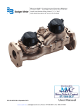
®
Badger Meter Europa GmbH
LMS-RF-Low End
Oil-Management System
INSTRUCTION MANUAL
October 2008 (v. 1.08)
LMS_RFL_BA_02_0810
Contents
1. Introduction ............................................................................................................................ 1
1.1
Composition and dataflow of the RF-System .......................................................................... 1
1.2
Operation modes......................................................................................................................... 2
1.2.1 RF-System in normal mode .............................................................................................. 2
1.2.2 Calibrating / PTB mode .................................................................................................... 2
1.3
Overview ...................................................................................................................................... 2
2. Dispense keypad .................................................................................................................... 3
2.1
Technical data ............................................................................................................................. 3
2.2
Wall fastening of the dispense keypad ..................................................................................... 3
2.3
Keypad description ..................................................................................................................... 4
2.4
Standard screen .......................................................................................................................... 5
2.5
Settings / supervisor menus ...................................................................................................... 5
2.6
Menu INI (system initialisation) ................................................................................................. 5
2.7
Tank initialisation ........................................................................................................................ 6
2.7.1 Select fluid ........................................................................................................................ 7
2.7.2 Assign tank - product ........................................................................................................ 7
2.7.3 Create hose / meter .......................................................................................................... 8
2.7.4 Assign meter – tank .......................................................................................................... 8
2.7.5 Delete hose / meter .......................................................................................................... 9
2.7.6 Creating and deleting operators ....................................................................................... 9
Enter the PIN of the operator you want to delete.......................................................................... 9
2.7.7 Flowchart menu INI ........................................................................................................ 10
2.8
Menu CNF (configuration) ........................................................................................................ 11
2.8.1 Clear transactions ........................................................................................................... 11
2.8.2 System reset ................................................................................................................... 11
2.8.3 Mileage info and registration Info ................................................................................... 11
2.8.4 Flow chart menu CNF ..................................................................................................... 11
2.9
Menu MET (delete) .................................................................................................................... 12
2.10
Menu REP (reports) .................................................................................................................. 12
2.11
Menu 190 (internal printer) ...................................................................................................... 12
2.12
Menu flow chart ........................................................................................................................ 13
2.13
Dispense / start a work order .................................................................................................. 14
2.13.1 Overview ........................................................................................................................ 14
2.13.2 Process .......................................................................................................................... 14
2.14
Functions overview .................................................................................................................. 16
3. LM OG-RF meter ................................................................................................................... 17
3.1
Key description ......................................................................................................................... 17
3.2
RF mode (standard) .................................................................................................................. 18
3.2.1 Procedure ....................................................................................................................... 18
3.2.2 Illustration ....................................................................................................................... 18
3.3
Auto mode (autonomous) ........................................................................................................ 19
3.3.1 Procedure: ...................................................................................................................... 19
3.3.2 Reset to standard mode ................................................................................................. 19
3.4
Electrical override ..................................................................................................................... 19
3.5
Changing the battery ................................................................................................................ 19
3.6
Programming the LM OG-RF meter......................................................................................... 19
Contents
4. Troubleshooting ................................................................................................................... 20
4.1
Dispense keypad error messages ........................................................................................... 20
4.2
Other problems ......................................................................................................................... 20
5. Worksheets ........................................................................................................................... 21
6. Manufacturer´s declaration ................................................................................................. 24
7. Warranty ................................................................................................................................ 25
8. DIN ISO certificate ................................................................................................................ 25
Introduction
page 1/25
1. Introduction
The Badger Meter oil management system is designed to control and monitor the
consumption and inventory balances of automotive fluid products with minimal installation
and programming costs. Badger has used its years of expertise in the automated meter
reading market to develop a modular control system utilizing RF communications.
The RF oil management system hardware consists of one dispense keypad and at least
one radio frequency electronic preset meter (LM OG RF). The system verifies the
operator’s pin number and validates the work order number, fluid quantities and the valid
hose / meter.
The dispense keypad can control up to 48 meters. The system supports up to 8 tanks and 8
fluids as a part of the system configuration. The system supports 150 unique operator IDs
and pin numbers.
The system utilizes spread spectrum frequency hopping RF technology to prevent
communication problems with other equipment in the facility. The RF system will look for a
clear channel for transmission to insure that there is reliable communications at all times.
Communication distances are typically up to 100 m but can go up to 300 m on plain areas.
The dispense keypad is used to configure the system, maintain system data and enter work
orders. The service desk would utilize the dispense keypad to enter a work order selecting
the fluid and quantity required. There is no need to predetermine where the work is going to
occur. This allows the flexibility to service a vehicle at any open bay and select a meter
when the work is going to be performed. When the work order is going to be performed the
service operator simply enters his pin number, work order and hose that is going to be used
at the dispense keypad.
There are a number of system utilization reports by user; fluid type, tank or meters available
for the system’s management.
A unique, patented feature of the system is that the RF meter’s dispense trigger is locked
until an authorization from the dispense keypad is received. After the dispense is
completed, the user can top off the dispense, the actual dispensed amount is sent back to
the keypad and the meter returns to the locked status. Additionally, the meter can be
installed on portable dolly systems offering control and monitoring of high-cost lubrication
products.
1.1 Composition and dataflow of the RF-System
Work order data
Dispense data
Dispense terminal
1200
dispenses
Printer
RS 232
LMS_RFL_BA_02_0810
Introduction
page 2/25
1.2 Operation modes
1.2.1 RF-System in normal mode
Work orders are entered at the dispense keypad and carried out with the meters.
1.2.2 Calibrating / PTB mode
Operation in accordance with the specifications of the Physikalisch Technische
Bundesanstalt (PTB) in Braunschweig.
Based on the German act of measurement and calibrating §13 from March 23rd,1992.
•
•
•
•
Detection of small quantities (less than 0,5 litres)
Detection of faulty impulses at the RF-meters
Storing of the dispense data for at least 3 months in the data logger (RF-Memory).
A PTB-approved meter is neccessary (green keypad).
1.3 Overview
Dispense
terminal
Printer
Operators
Tank 1
Product 1
Tank 2
Product 2
LMS_RFL_BA_02_0810
Tank 3
Tank 4
Product 3
*
Dispense keypad
page 3/25
2. Dispense keypad
The dispense keypad is used to configure the system, maintain system data and enter work
orders. The service desk would utilize the dispense keypad to enter a work order selecting
the fluid and quantity required. To change system settings the supervisor PIN has to be
entered.
2.1 Technical data
Power supply
230 VAC 50/60 Hz
EMC-approval
EN300 220-1
RF communication
2-way 868MHz according to FCC
part 15.247 and part 15.109
16 bit encryption
Operating temperature
-10° C to +60° C
Internal printer
Thermal printer Type FT190 (optional)
External printer
Epson LX300 or similar (optional)
2.2 Wall fastening of the dispense keypad
The keypad should be mounted upright with the antenna pointing upward, near a 230
VAC electrical socket, to a structurally sound wall through the two holes on the top of
the keypad casing. Height on the wall should be at eye level. Care should be taken to
avoid mounting behind any steel objects (tool storage cabinets and metal chain linked
fences) that may block the RF communication signal. Care should also be taken to
avoid direct, significant heat sources.
97
187
Mounting dimensions for keypad
bore diameter: 5 mm
LMS_RFL_BA_02_0810
Dispense keypad
page 4/25
2.3 Keypad description
Internal printer
Type FT190
Power supply
230 VAC 50/60Hz
External printer
port (RS 232)
Scroll key: Used to select options on the active display
Home key: Pressing this key will return display to the PIN number and
time/date screens
Backspace key: Used to backspace when entering data
Enter Key: Used to enter data and move to the next screen
Space key: Used to enter a space character when entering data
Alphanumeric keys: Used to enter data on display. Hold down key until
desired character is on display. Then release the key.
LMS_RFL_BA_02_0810
Dispense keypad
page 5/25
2.4 Standard screen
The standard screen shows the system date and software
version number. The display will alternate between the
standard screen and the enter pin number screen.The enter
pin n° screen is used to access the supervisor menues.
12feb2005
12:48
*Version 1.08
A star ahead of the version number indicates the PTB mode.
enter a mechanic’s PIN to start a wo or the supervisor PIN to enter setup (default:
0000).
Enter PIN
+
2.5 Settings / supervisor menus
Menu INI
is used to configure the system and to associate the system components.
Menu CNF is used to change system settings.
Menu MET is used to delete pending work orders.
Menu REP is used to print out system settings and work order reports at an external
printer.
Menu 190
printer.
is used to print out system settings and work order reports at the internal
2.6 Menu INI (system initialisation)
This menu is used to set date and time, tank and product data, meters (/hoses) and
operators.
Always go through all menu steps, even if you just want to change a few
settings.
Choose the menu INI and press enter.
Enter time
--:--
+
Format hh:mm
enter the actual time (two / four digits) and press enter.
Enter date
--/--/----
+
Format dd.mm.yyyy
Enter the date. Scroll from left to right through the fields by using the scroll key (the
date cannot be changed in PTB-mode).
The screen changes to tank unit.
LMS_RFL_BA_02_0810
Dispense keypad
page 6/25
2.7 Tank initialisation
Before starting the tank initialisation, set the following issues:
(You can use the work sheets provided in chapter 5)
1.
2.
3.
4.
5.
6.
Set the tank number for each tank (1-8).
Assign the oil types to the corresponding tanks
Take down the actual levels in the tanks
Keep the meters in reach.
Assign each meter to a tank.
set name and PIN for each user / operator
The tanks are entered considering the following conditions:
•
•
•
•
•
A maximum of 8 tanks.
Tank number from 1 to 8.
The default measurement unit is liters.
The tank level in the system is being automatically refreshed after a dispense.
Level format: 99999,999.
Start to enter the tank number (1-8) and a level (with corresponding unit) for each tank
now.
Tank Unit
Tank No =
Enter a number between 1 and 8
Tank Unit No X
<- LITER ->
You can change between: < LITER, GALLONS, PINTS, QUARTS and REMOVE >
Tank Stock Level
No X --------Enter the actual level.
Repeat these steps for the other tanks. If you do not want set further tanks enter
no tank number and press
The screen changes to select fluid.
LMS_RFL_BA_02_0810
Dispense keypad
page 7/25
2.7.1 Select fluid
The fluid types are entered considering the following conditions:
• A maximum of 8 types (oil, antifreeze, etc.).
• The label can consist of numbers and letters.
• There are no predetermined labels
Select Fluid
No =
Enter a fluid number (1-8).
Fluid No X
---------
Enter a valid type label e.g. 5W 38 Mo.
Repeat these steps for the other fluids. If you do not want set further fluids enter
no number and press
2.7.2 Assign tank - product
The tank- / product assignment is 1:1. Each tank is assigned to one fluid type. E.g. tank
no 1 is assigned to fluid no 1 or tank no 1 is assigned to fluid no 2
Tank-Fluid
Tank No =
+
Enter the tank number you want to assign with
a fluid
Tank-Fluid
Fluid No =
+
Enter the fluid number you want to assign with
this tank.
Repeat these steps until all fluids are assigned to their tanks. If you do not want
to assign further tanks, enter no tank number and press
The screen changes to create hose.
LMS_RFL_BA_02_0810
Dispense keypad
2.7.3
page 8/25
Create hose / meter
• The label with the meter’s serial number
and RF address is located in the
battery compartment.
•
•
•
•
•
RF address
0.0xx.xxx.xxx
The RF address has 10 digits.
Meters can be created and deleted.
A maximum of 48 meters can be created.
The dispense keypad can only communicate with a registered meter.
All addresses are clear.
Create hose
+
-.---.---.---
(e.g. 0 036 700 061)
• If the adress is already assigned the following display will indidcate that:
Hose Address
already used
Background: The system is checking the last three digits of the entered RF
address. If this message appears, please make sure that you are not creating a
meter already in use.
2.7.4
Assign meter – tank
Now assign the created meter to its tank.
Therefore enter the corresponding tank number.
Tank - Hose
Tank No X
+
• The assignment to a tank is 1: n
(i.e. one tank can be assigned to several meters. Because each tank is assigned to
one fluid type, all these meters are automatically assigned to the same fluid type).
Repeat these steps until all meters are assigned to their tanks. If you do not want to
assign further meters, enter no tank number and press
The screen changes to delete hose.
LMS_RFL_BA_02_0810
Dispense keypad
2.7.5
page 9/25
Delete hose / meter
If a meter has to be replaced, it has to be deleted in the system by using this function.
Delete Hose
- , - - - , - - - , - - -
+
When replacing a meter the new one will be set on the deleted one’s position.
2.7.6
•
•
•
•
•
Creating and deleting operators
Work orders can only be started with a valid operator PIN.
A maximum of 150 operators can be created.
The PIN is a 4-digit number.
The operator name can consist of a combination of numbers and letters.
At the beginning the operator list is empty.
New operator
----
+
Enter the 4-digit operator PIN you have set
for this operator
New operator XXXX
_ _ _ _ _ _ _ _ _ _
+
Enter a name.
Repeat these steps until all operators are created. If you do not want to create
further operators press
Delete Operator
_ _ _ _
+
Enter the PIN of the operator you want to delete
If you do not want to delete any operator press
You are now leaving the INI menu.
LMS_RFL_BA_02_0810
Dispense keypad
2.7.7
page 10/25
Flowchart menu INI
INI
Select
CNF MET
REP
190
Select
. . . . . .
Order list
Not empty
Enter time
--:--
Date
--/ jan /----
Tank unit
Tank No-
Tank Unit X
<- LITER ->
Select fluid
No -
Fluid No X
- - - - - - - - - - -
Tank - Fluid
Tank No-
Tank - Fluid
Fluid No -
Create hose
-,---,---,---
Hose Address
already used
delete hose
-,---,---,---
New Operator
----
5 sec
New Operator XXXX
---------
Delete operator
- - - -
LMS_RFL_BA_02_0810
Not available in PTBmode.
Tank stock level
No X : - - - - - - -
Tank - Hose
Tank No X
Dispense keypad
page 11/25
2.8 Menu CNF (configuration)
The menu is used to change system settings.
2.8.1
Clear transactions
These functions allow to delete all finished work orders.
2.8.2
System reset
This function is used to set the system back to factory settings.
2.8.3
Mileage info and registration Info
Regist. info
YES / NO
Mileage info
YES / NO
+
Alphanumeric field with 16 digits.
Can be used for the car’s registration number
+
Numeric field with 12 digits.
Can be used for entering the car’s mileage
Change from numeric to alphanumeric keys: Press the key for at least 3 sec. until the desired
character is on the display. Then release the key.
2.8.4
Flow chart menu CNF
CNF
Clear transacts
YES / NO
Print WO
Enter to print
System Reset
YES / NO
Confirm reset
YES / NO
MIleage type
KM / Miles
Mileage info
YES / NO
Regist. info
YES / NO
Keypad timeout
10Internal printer
YES / NO
External printer
YES / NO
Printer address
000
Approved PTB
Yes
Super new pass
****
Buzzer
YES / NO
LMS_RFL_BA_02_0810
Confirm clear
YES / NO
Dispense keypad
page 12/25
2.9 Menu MET (delete)
Work orders that have been entered at the keypad are being stored untill they will be
picked up by the propriate meter (by pressing RESET at the meter). Meanwhile the
meter is locked for other suspenses.
By using this menu, the prepared work orders can be deleted to release the meter for
new work orders.
Init all hose
YES / NO
+
+
Start Hoses Init
Press enter
YES
All pending work orders will be deleted.
NO
You can select single wos to be deleted by entering the propriate meter / hose
Hose Init
Hose no __
2.10
+
+
+
Menu REP (reports)
By using this function reports about the following subjects can be printed out by an
external printer:
Select Report ->
INI CNF COM ORD
INI
CNF
COM
ORD
Select Report ->
MEC PRO HOS SRB
Initialising
Configuration
not set
sort list work order
+
MEC
PRO
HOS
SRB
+
sort list by operator /mechanic
sort list by product
sort list by hose / meter
sort list by tank
An appropriate printer or a PC (terminal program) can be connected to the serial
printer port (RS 232).
Settings: 9600 Baud, Data Bits 8, Stop Bits 1, Parity None
2.11 Menu 190 (internal printer)
By using this menu, the configuration and status reports can be printed out by the
internal printer FT 190.
Menu Example
FLU
FLUID address: 258 Size: 18
1-> 1 / SAE10W40
HOS HOSE address: 142 Size:12
1-> 0.036.700.715 / 1
TNK TANK address: 194 Size: 8
1-> 10000 / LITER
USE USER address: 402 Size: 20
1-> 1234 / HR.MUELLER
WO
WO 1 485801020230022B
Menu Example
PEN Meter 1 inactive (or asking)
PAR
MEM
Unit
Km (or Miles)
AN-Field
Yes
...
etc.
Item Size Max Nb Adress Between
----- ---- ---- ---- ------ ---------...
etc.
LMS_RFL_BA_02_0810
Dispense keypad
page 13/25
2.12 Menu flow chart
LMS_RFL_BA_02_0810
Dispense keypad
page 14/25
2.13 Dispense / start a work order
2.13.1 Overview
2.13.2
Process
1.) Enter PIN
To start a work order a mechanic / user enters his PIN.
2.) Enter work order number
Work order number: Enter an alphanumeric number (max. 16 chars) and press Enter.
Enter Job No.
________________
+
Alphanumeric keypad: To change from the numeric to the letter keypad press the
equivalent key for at least 3 seconds until the desired letter is shown.
3.) Enter AN-field and N-field
These optional fields are only shown, if they have been enabled.
Regist. info
________________
Mileage info
____________
+
alphanumeric field, 16 chars:
Can be used for the registration number
+
numeric field, 12 chars:
Can for example be used for the actual mileage
Alphanumeric keypad: To change from the numeric to the letter keypad press the
equivalent key for at least 3 seconds until the desired letter is shown.
LMS_RFL_BA_02_0810
Dispense keypad
page 15/25
4.) Preset meter selection
Enter a preset meter ID, that is aligned to the desired product.
Enter hose
__
+
5.) Display fluid
The choosen fluid type is shown for three seconds.
fluid type
XXXXXXXXXXXXXXXX
3 sec.
6.) Enter product quantity
Enter the desired quantity. Optionally, the quantity assigned to this wo is shown.
Enter quantity
0___
+
• The quantity can be chosen between 0,0 - 99,9 and 100 - 999 liters. The maximum
quantity in the PTB-mode is 90,0 liters. A quantity less than 0,5 liters will be indicated
as not calibrateable (no star).
• The pre-selection can be made with one decimal place.
• Quantities of more than 100 liters will be displayed decrementally.
• A quantity of 0.0 will put the RF meter in a free-dispense mode, the RF meter will
not latch and the user may dispense fluid as long as the trigger is manually held in the
open position. The user must press RESET on the RF meter to exit this dispense and
communicate the dispense order to the keypad.
7.) Dispense confirmation
Press Enter to confirm the dispense.
Press Enter for
dispense
+
The work order is now ready for being picked up by the RF-meter.
(See chapter 3.2 ”RF mode (standard) “)
LMS_RFL_BA_02_0810
Dispense keypad
page 16/25
2.14 Functions overview
Enter PIN No.
----
Enter job No.
---------------
Please
wait
Enter Hose
--
Enter quantity
---Press enter for
dispense
INI
Enter time
--:--
CNF
Clear transacts
YES / NO
190
MET
REP
Init All Hose
YES / NO
Select Report ->
Select Report ->
INI CNF COM ORD
FLU HOS TNK USE
Select Report ->
Select Report ->
MEC PRO HOS SRB
WO PEN PAR MEM
LMS_RFL_BA_02_0810
LM OG RF meter
page 17/25
3. LM OG-RF meter
The meter is equipped with RF communications allowing authorization and dispense information. Once a work order has been set up, the operator simply pulls the trigger and the
authorized amount of fluid for that meter will dispense. The valve will automatically shut off
when the full quantity has been dispensed. A “top off” feature allows additional quantities to
be dispensed and tracked after the valve closes. Upon completion of the dispense effort, the
valve locks prohibiting any unauthorized dispense to occur.
For more detailed instructions, see the LM OG P manual delivered with the meter.
3.1 Key description
The following keys (except for RESET and SHUT-OFF) are only active in the
autonomous mode (described down below)
10 - History
Used to enter the quantity to be dispensed (10 liter steps).
In operational mode it shows the five latest dispensed amounts.
1
Used to enter the quantity to be dispensed (1 liter steps).
0.1 - Flow
Used to enter the quantity to be dispensed (0.1 liter steps).
In operational mode it shows the actual dispension flow.
TOTAL
Used to display the accumulated total of fluid, as well as the resettable total
(hold for 3 seconds) during operational mode.
AUTO
Used to enter and exit the auto mode when RF communications are not
available.
RESET
Used to accept a dispense order from the keypad. Used in normal operating
mode (RF, manual or auto) to clear the previously programmed batch and to
reset the meter. Press the button while viewing the resettable total to set it
back to zero.
Shut-off
Used to stop the flow manually through an electrical override.
LMS_RFL_BA_02_0810
LM OG RF meter
page 18/25
3.2 RF mode (standard)
Work order validation via the dispense keypad.
When the battery pack is attached to the
meter, the meter will automatically enter
the RF mode. The trigger is in a lockedout position and no oil can be dispensed
until a dispense order is received by the
meter.
RF mode
3.2.1 Procedure
1. Press the
button
on
the
meter to enable it to receive a
dispense order provided by the
dispense keypad. The trigger will
unlock.
batch size
2. Pull the trigger to begin the flow. The valve will automatically lock in place, even
though the trigger will fall back to the closed position. The flow will automatically
shut off when the preselected quantity has been dispensed.
3. To top off, pull the trigger to begin the flow and release when the desired amount
has been pumped.
4. Press the
button when finished. The total quantity dispensed will be
transmitted to the keypad and the meter will return to a locked-out position. The
meter is now ready to receive the next dispense order from the keypad.
3.2.2 Illustration
LMS_RFL_BA_02_0810
LM OG RF meter
page 19/25
3.3 Auto mode (autonomous)
Attention: This function allows unauthorized dispenses. The dispenses will not be
assigned to any mechanic / operator.
- Operation will take place with the normal functions.
- The total dispensed quantity will be stored under the general work order number
(999999)
- The . AUTO . sign at the display’s lower left corner indidcates the autonomous mode
3.3.1 Procedure:
Program the meter to auto mode by holding down the
,
,
,
and
button and pressing
.
The solenoid will now unlock and the meter may be used as a normal meter.
3.3.2 Reset to standard mode
To set the meter back into standard mode advice a work order from the assigned
dispense keypad to it (see chapters 2.13 und 0 for the procedure). After terminating the
work order, the meter will lock and set back to standard mode.
3.4 Electrical override
In case of an emergency or to interrupt a batch, the meter is equipped with an
electrical override. This option automatically closes the valve in the meter, stopping
the flow immediately. The display will begin to flash because the meter does not sense
any flow. Batching can be continued after an override, even if the meter is in the middle
of a programmed batch and the display continues to flash.
Press the red
button to activate the electrical override. This button can only be
used when the valve is open.
Press the
button to cue up the next batch and stop the display from flashing.
3.5 Changing the battery
When the batteries need to be changed, a progression of warnings will appear on the
screen.
The battery compartment is located on the underside of the trigger guard. Unscrew the
two screws located under the guard and remove the battery cover to expose the
batteries.
3.6 Programming the LM OG-RF meter
The units of measurement, scale factor and the pulse delay factor can be changed. To
enter / leave the programming mode, press and hold the "PROGRAMMING" key
located in the access hole at the meter’s bottom for 2 seconds.To gain acces to this
key, a seal has to be broken.
For more detailed instructions see the LM OG P manual delivered with the meter.
LMS_RFL_BA_02_0810
Troubleshooting
page 20/25
4. Troubleshooting
4.1 Dispense keypad error messages
These error messages can be displayed by the dispense keypad. The associated
action to reset the system is listed behind.
Message
Wrong hose
for fluid
Radio
communication
Description and error recovery
The meter selected is not a valid meter for the fluid
assigned for this work order.
System communication is in progress, please wait.
Keypad
interface error
The meter has a work order on process. Please complete
this work order or press reset on the meter to reset the
status.
Key hose Int Err
Reset on hose
An error occurred during communications to the meter,
please press reset on the meter to retry the
communications.
Pending WO
Please res. hose
Order list
not empty
KEYPAD ERROR
The meter has already been selected for a dispense.
Complete the dispense or reset the hose status to
continue.
To change settings in the INI menu, all work orders have
to be deleted first.
Carry out in menu CNF „clear transacts“ and in
menu MET „Init. all hose“ to delete all wos.
An error occurred in the keypad.
Press RESET on the meter.
HOSE AFFECTED
HIT HOSE RESET
The selected meter currently has a dispense order in
processor waiting to be processed, complete the active
order.
The user should clear out the requested dispense by
selecting MET in the Supervisor Menu.
Hose has
ongoing WO
The hose has a work order in process. Please complete
this work order or press rest on the meter to rest the hose
status.
4.2 Other problems
Problem:
Meter:
The AUTO function is shut off, the
auto icon disappeared and can not be
activated again.
It is not possible to set back the meter
from auto mode to standard mode.
Description and error recovery:
The battery sign is flashing in the lower left corner.
This means the battery power is too low to run the
auto function. The meter can still run in manual
mode. Change the batteries.
Carry out in menu MET „Init. all hose“ to
delete all wos at the dispense keypad
Afterwards send a new work order to the meter.
LMS_RFL_BA_02_0810
Worksheets
page 21/25
5. Worksheets
Fluid ID
Fluid name
1
2
3
4
5
6
7
8
A maximum of 8 products.
The alphanumeric name, max. 16 chars.
Tank ID
1
Fluid
Tankvolume
2
3
4
5
6
7
8
Maximum 8 Tanks.
Tank volume format: 00000.000.
LMS_RFL_BA_02_0810
Unit
Content
Worksheets
Meter ID
page 22/25
Address x . xxx . xxx . xxx
1
2
3
4
5
6
7
8
9
10
11
12
13
14
15
16
17
18
19
20
21
22
23
24
Max 48 meters/hoses.
The address is a 10 digit number.
LMS_RFL_BA_02_0810
Worksheets
page 23/25
User ID
Name user
Supervisor
1
2
3
4
5
6
7
8
9
10
11
12
13
14
15
16
17
18
19
20
21
22
23
24
25
26
27
28
29
30
31
32
33
34
35
36
37
38
39
40
41
42
43
44
45
Up to 150 users. The user field is alphanumeic, max. 16 chars.
The user PIN ID is a 4 digit number
LMS_RFL_BA_02_0810
PIN ID
0000
Manufacturer´s declaration
page 24/25
6. Manufacturer´s declaration
LMS_RFL_BA_02_0810
Warranty / DIN ISO certificate
page 25/25
7. Warranty
Badger Meter warrants meters and parts manufactured by it and supplied hereunder to be
free from defects in materials and workmanship for a period of 18 months from date of
shipment or 12 months from date of installation, whichever period shall be shorter. If within
such period any meters or parts shall be proved to Seller´s satisfaction to be defective, such
meters or parts shall be repaired or replaced at Seller´s option. Seller´s obligation hereunder
shall be limited to such repair and replacement and shall be conditioned upon Seller´s
receiving written notice of any alleged defect within 10 days after its discovery and, at
Seller´s option, return of such meters or parts to Seller, f.o.b. its factory. THE FOREGOING
WARRANTY IS EXCLUSIVE AND IN LIEU OF ALL OTHER EXPRESS OR IMPLIED
WARRANTIES WHATSOEVER INCLUDING BUT NOT LIMITED TO IMPLIED
WARRANTIES (EXCEPT OF TITLE) OF MERCHANTABILITY AND FITNESS FOR A
PARTICULAR PURPOSE. Badger Meter shall not be liable for any defects attributable to
acts or omissions of others after shipment, nor any consequential, incidental or contigent
damage whatsoever.
8. DIN ISO certificate
LMS_RFL_BA_02_0810
Hotline
Tel :
Fax :
E-Mail :
+49-7025-9208-0
+49-7025-9208-14
[email protected]
®
Badger Meter Europa GmbH
Subsidiary of Badger Meter, Inc.
Nürtinger Strasse 76
72639 Neuffen (Germany)
E-Mail: [email protected]
www.badgermeter.de